Power Cable Accessories
Power Cable Accessories
Power Cable Accessories

You also want an ePaper? Increase the reach of your titles
YUMPU automatically turns print PDFs into web optimized ePapers that Google loves.
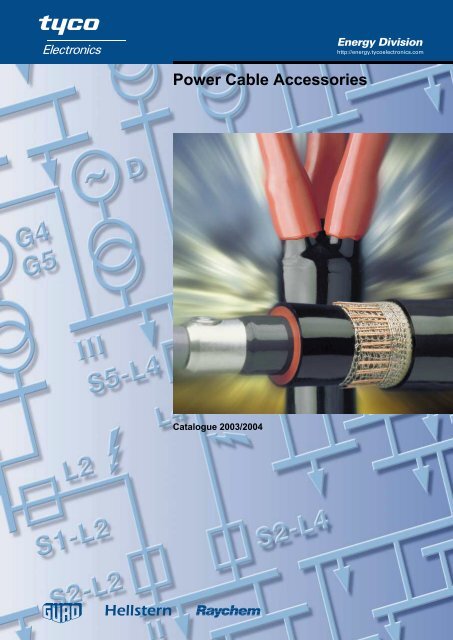
<strong>Power</strong> <strong>Cable</strong> <strong>Accessories</strong><br />
Catalogue 2003/2004<br />
Energy Division<br />
http://energy.tycoelectronics.com
Content<br />
Introduction 3<br />
Terminations – Low and Medium Voltage 15<br />
Connection Systems for gas-insulated<br />
Switchgear up to 24 kV 37<br />
Joints – Low Voltage 47<br />
Joints – Medium Voltage 67<br />
Sealing Systems 85<br />
Repair Sleeves and Tubings 93<br />
Tools and <strong>Accessories</strong> 101<br />
Connection Boxes 109<br />
1
Introduction<br />
Introduction<br />
General 4<br />
Low Voltage Jointing System 7<br />
Medium Voltage Terminations System 8<br />
Medium Voltage Jointing System 9<br />
Electrical Stress Control in <strong>Cable</strong> <strong>Accessories</strong> 10<br />
Weathering and Ageing Resistivity 11<br />
Technology of Heat-Shrinkable Products 12<br />
Advantages of Raychem Heat-Shrinkable Products 13<br />
3
4<br />
Tyco Electronics Energy Division<br />
We develop, manufacture and market innovative products which benefit from its<br />
advanced know-how in the field of material science. All products are designed to help<br />
our customers to improve the reliability and economy of their electrical networks and<br />
equipment. Our broad portfolio of products offered for the electrical power industry<br />
include cable accessories, surge arresters, insulators, insulation enhancement<br />
products, components for electrical equipment as well as connectors and fittings for up<br />
to 800 kV.<br />
This catalogue contains terminations, joints, connection boxes and accessories for<br />
cable types most commonly used in the electrical distribution and industrial networks of<br />
Central & Eastern Europe / CIS (change to your country!). As one of the largest<br />
suppliers of cable accessories in the world, Raychem products are offered for nearly all<br />
special and foreign cable constructions. Please contact the Raychem products<br />
representative for technical support and additional information about cable accessories<br />
or the other product lines.<br />
Raychem cable accessories<br />
As a result of sustained and extensive research and long experience in technical<br />
support work, Raychem products are developed during the last 3 decades to become a<br />
complete system of cable accessories up to 170 kV.<br />
The long-term performance of Raychem heat-shrinkable materials has been<br />
demonstrated by the well-proven Raychem accessory system. Millions of installations in<br />
some of the most severe service conditions have confirmed the reliability of the<br />
Raychem heat-shrinkable technique under high electrical, thermal and environmental<br />
stress.<br />
The technology that is common to all Raychem heat-shrinkable cable accessories is<br />
based on radiation crosslinked polymers with an elastomeric shape memory. They<br />
provide a significantly improved mechanical, chemical and thermal resistance compared<br />
to non-crosslinked products.<br />
Raychem cable accessories are distinguished by their good insulating and sealing<br />
characteristics, high mechanical toughness and resistance to weathering and<br />
chemicals, such as UV radiation and alkaline soils. Because of the large shrink area of<br />
the individual parts, it is possible to use a few standard accessories to cover a large<br />
range of different cable types and cross sections. This means that warehousing is<br />
simple and economical. In addition, Raychem cable accessories can be stored for an<br />
unlimited length of time under normal conditions.<br />
The product line includes indoor and outdoor terminations, inline and transition joints as<br />
well as universal insulation, sealing and repair systems for use in the cable network. All<br />
medium voltage accessories include a stress control system either as separate stress<br />
control tubing or integrated as stress control coating in an insulating tubing. In<br />
terminations, the insulating tubing ensures a non-tracking and erosion resistant surface<br />
and provides an environmental seal to the cable lug and the oversheath. The<br />
connection area of joints is covered by an elastomeric dual-wall tubing which provides<br />
an interface free insulation and an outer screening.
Installation<br />
No special tools are required for the cable preparation. The installation of the heatshrinkable<br />
parts is performed with a propane gas torch which is usually also used for<br />
the preparation of paper and plastic cables. When delivered, all individual parts are<br />
stretched so far that they can easily be slid over the prepared cable end. When<br />
sufficiently heated, they shrink and firmly enclose the cable and protect it against<br />
moisture, while the adhesive melts and fills all grooves and voids. Raychem cable<br />
accessories are constructed in a similar way to the cables themselves and can, like<br />
these, be bent in narrow spaces. Upside-down installations of terminations are possible<br />
simply by turning the heat-shrinkable sheds. The accessories can immediately put into<br />
operation after installation.<br />
Test process and qualification<br />
Raychem cable accessories are designed and fully tested to meet Raychem<br />
specification PPS 3013 which encompasses the requirements of major national and<br />
international standards, e.g.: IEC, CENELEC, GOST, BS CSN, MSZ, PN, STN, STR,<br />
VDE, etc. Test reports are available which document the tests performed in test<br />
institutes and in Raychem laboratories on the long-term electrical and environmental<br />
behaviour of cable accessories and materials.<br />
The currently relevant CENELEC standards tested to are:<br />
HD623.S1:1995 – Specifications for joints, stop ends and outdoor terminations for<br />
distribution cables of rated voltage 0,6/1,0 (1.2) kV<br />
HD629.1.S1:1996 – Test requirements on accessories for use on power cables of rated<br />
voltages from 3,6/6 (7,2) kV up to 20,8/36 (42) kV.<br />
Part 1: <strong>Cable</strong>s with extruded insulation.<br />
HD629.2.S1:1997 – Test requirements on accessories for use on power cables of rated<br />
voltages from 3,6/6 (7,2) kV up to 20,8/36 (42) kV.<br />
Part 2: <strong>Cable</strong>s with impregnated paper insulation.<br />
For product testing and selection we follow the classifications for rated voltages<br />
Uo/U (Um) as referred to in IEC and Cenelec standards:<br />
Uo is the rated power-frequency voltage between phase conductor and earth or<br />
metallic screen for which the cable accessory is designed.<br />
U is the rated power-frequency voltage between phase conductors for which the<br />
cable accessory is designed.<br />
Um is the maximum value of the ‘highest system voltage’ for which the cable accessory<br />
may be used.<br />
To cover all typical voltages in distribution networks, Tyco Electronics Energy Division<br />
tests cable accessories to the highest sets of rated voltages: 3,8/6,6 (7,2) kV<br />
6,35/11 (12) kV, 8,7/15 (17,5) kV, 12,7/22 (24) kV, 19/33 (36) kV and 20,8/36 (42).<br />
The quality standards of all materials throughout the entire manufacturing process<br />
beginning with the raw materials and continuing through to the packaged product are<br />
continuously monitored and documented. Materials as well as complete accessories are<br />
regularly requalified. As a result of our well established Quality Management System<br />
including quality assurance, Tyco Electronics Energy Division was one of the first in the<br />
industry to achieve a certification according to ISO 9001.<br />
Service<br />
Even the best technology can be applied in the wrong way. To avoid such situations, we<br />
have established a technical support service to provide technical information and<br />
application guidelines for our customers, such as cable fitters, project and maintenance<br />
engineers, constructors, equipment manufacturers and specification and purchasing<br />
engineers.<br />
A sound and practice oriented range of services is provided:<br />
O Presentations and Seminars<br />
O Technical papers focusing on<br />
new industry trends and products<br />
O Training in cable preparation, installation techniques<br />
and product selection for engineers and installers<br />
O Practical demonstrations and field installations<br />
O Solutions to specific customer problems<br />
5
6<br />
Quality Standards, Environment, Health and Safety<br />
The quality standards of all materials throughout the entire manufacturing process<br />
beginning with the raw materials and continuing through to the packaged product are<br />
continuously monitored and documented. Materials as well as complete accessories are<br />
regularly requalified. As a result of our well established Quality Management System<br />
including quality assurance, Tyco Electronics Energy Division continuously achieves recertification<br />
according to ISO 9001.<br />
Regular installations of Raychem heat-shrinkable cable accessories are considered to<br />
present no risk to health based on investigations by independent test institutes and<br />
customer evaluations. Moreover, hazards typically associated with cable accessory<br />
installations can be eliminated by avoiding any soldering or handling of conventional<br />
2 component or bitumen fillers. No messy or harmful residues requiring special or costly<br />
disposal are left over after installation.<br />
Only ecologically sound and recyclable components are used and packaging materials<br />
are continuously reduced. Our efforts and investments over the years in improving the<br />
environment led not only to the elimination of ozone-depleting materials and substantial<br />
reductions of waste materials and water consumption but also to new processes<br />
allowing crosslinked materials to be recycled. As a result of these efforts, we have<br />
successfully completed the environmental assessment in accordance with ISO 14001<br />
and received a certification as one of the first companies in the industry.<br />
Ordering and delivery<br />
All cable accessories come complete with the necessary electrical insulation materials,<br />
installation instructions (in local language) and a bill of material. Solderless earth<br />
connections are either included in the kits or can be ordered separately. <strong>Cable</strong> lugs and<br />
connectors are only included if specifically stated. Medium voltage termination kits and<br />
joint kits for 3-core cables include materials for all 3 phases, joint kits for single core<br />
cables only material for one phase.<br />
We continuously monitor delivery performance and lead times, look for opportunities<br />
to shorten cycle times and improve service. We also analyse our responsiveness<br />
throughout our distribution network to customers. This is not static, but rather a<br />
constantly improving process directed towards our goal: complete customer satisfaction.
Raychem Low Voltage Jointing System<br />
With extensive application over the last decades, the Raychem jointing system for mechanical or crimp connectors is widely used and<br />
acknowledged as a highly dependable and easy-to-install jointing method for conventional and modern cable types. The principle of<br />
the construction and the simple way of installation are described with a joint for 1 kV plastic insulated cables.<br />
Installation<br />
After preparation of the cable ends according to the installation instruction, the smaller<br />
inner tubings as well as the outer tubing are slipped over the cores.<br />
The conductors are now connected with mechanical or crimp connectors.<br />
All joints are designed to allow crossing of the cable cores.<br />
The inner tubings are positioned over the connectors and shrunk down to tightly fit the<br />
connectors and the core insulation ensuring an adequate wall thickness even around<br />
the more bulky mechanical connectors. At the same time the heat causes the adhesive,<br />
precoated on the inside of the tubings, to melt and flow. The resulting bond seals out<br />
moisture and corrosion and conforms to the thermal expansion of the cable.<br />
The outer tubing is positioned over the jointing area and shrunk. The mechanical and<br />
sealing functions of the oversheath are assured by this thick-walled tubing. A durable<br />
and repeatable seal is produced by means of a hot-melt adhesive pre-applied to the<br />
entire length of the tubing.<br />
The joint is complete and can be put into operation immediately.<br />
Construction<br />
1Outer tubing: Thick-wall protection<br />
against mechanical stresses and<br />
against moisture by sealing onto the<br />
oversheath.<br />
2 Inner tubings: Thick wall tubing<br />
providing electrical insulation and<br />
protection of the connection area<br />
against moisture inside the cable.<br />
3 Hot-melt adhesive<br />
1 3<br />
3 2<br />
7
Raychem Medium Voltage Termination System<br />
8<br />
1<br />
2<br />
3<br />
4<br />
1<br />
5<br />
Raychem developed during the 60’s a series of new polymers for use at medium and<br />
high voltage. The resulting materials possess exceptional resistance to prolonged<br />
electrical stress and weathering, but are also capable of being shrunk down quickly to fit<br />
and seal a cable. Raychem accessories provide an universal system of indoor and<br />
outdoor terminations for paper or plastic insulated cables, for single or three core<br />
cables, for cables with round or sector shaped conductors and most types of screening<br />
or armouring.<br />
The following describes the typical modules of a modern medium voltage termination:<br />
1Moisture sealing<br />
Durable sealing is achieved by special Raychem sealants on the inside of non-tracking,<br />
weather-resistant components. At the same time as the installer heats the tubings, the<br />
shrinking action causes the sealant to melt and flow into place.<br />
In case of three core cables, a sealant-lined heat-shrinkable breakout installed over the<br />
cores and cable crutch provides a sealed and weather-resistant surface from the<br />
connecting lugs to the oversheath.<br />
2 Compact and versatile stress control<br />
To meet the need for space-saving, flexible termination design, adaptable to different<br />
types of compact equipment, we developed a Raychem material with a carefully<br />
controlled non-linear impedance based on ceramic semiconductor technology (ZnO),<br />
which is applied in the form of a coating inside the tubing. When the tubing is shrunk,<br />
the stress control coating is softened by the applied heat and conforms and bonds to<br />
even irregular insulation surfaces to ensure a void free contact. Details of electrical<br />
stress control in Raychem terminations can be found on page 10.<br />
3 Non-tracking insulation tubing<br />
The superior non-tracking characteristics and long-term erosion resistance of Raychem<br />
terminations have been exhaustively demonstrated in comparative tests at major<br />
independent laboratories and Raychem’s own extensive development facilities. These<br />
results are borne out by the continuing performance of over a million units installed in<br />
tropical, desert, arctic and industrially polluted climates, confirming that Raychem<br />
terminations do not track even in severe service conditions and verifying their<br />
exceptional erosion resistance and reliability. The phenomenon of tracking and erosion<br />
is explained on page 11.<br />
4 Yellow void filler<br />
The semi-conducting void filler is easily applied in form of a short adhesive tape. It<br />
ensures that, independent of the type of semi-conductive screen or removal method, no<br />
air voids can cause discharges in the high stress area of the screen end.<br />
5 Earthing<br />
Earthing wires or braids are imbedded in the sealing mastic to prevent any corrosion by<br />
moisture ingress. For cables with tape screen or metal sheaths with armour solderless<br />
earthing systems are either provided within the termination kit or can be ordered<br />
separately.
Raychem Medium Voltage Jointing System<br />
Product design<br />
The design of a single-core joint for a<br />
polymeric insulated cable is described<br />
here. The same design principles are<br />
used for 3-core cables. For transition<br />
joints, special oil barrier tubings are used<br />
to transform draining oil (MI) as well as<br />
non draining oil (MIND) paper insulated<br />
cable into a quasi polymeric insulated<br />
cable with a radial field.<br />
Installation procedure<br />
The elastomeric joint component and the<br />
outer sealing sleeve are slid over the prepared<br />
cable end. The screen ends are<br />
electrically smoothed with a void filling<br />
compound and stress control tubings are<br />
shrunk over the cable ends. By simply<br />
tightening the bolts of the mechanical connector,<br />
the conductors are jointed and then<br />
covered with a stress control patch. The<br />
elastomeric component is quickly shrunk<br />
over the connection area. Roll springs and<br />
copper mesh rebuild the cable shield and<br />
the oversheath is replaced by an adhesive-coated<br />
sealing sleeve. All kits are<br />
supplied with illustrated step by step<br />
instructions.<br />
1 2 3 4<br />
1Electrical stress control<br />
The stress control tubing and the patch have a precisely defined impedance<br />
characteristic which smoothes the electrical field over the connector and cable screen<br />
ends. During installation of the tubings, its shrinking action compresses the special void<br />
filler (yellow) and the patch into position round the screen ends and the connector.<br />
Pencilling of the insulation at the connector is not necessary.<br />
2 Insulation and screen<br />
The elastomeric sleeve provides the correct thickness of insulation (red) in one step.<br />
The insulation screen is provided by the outer wall of the sleeve, which is of heatshrinkable<br />
conductive polymer (black). This technique saves installation time and<br />
ensures a flawless bond between joint insulation and screen.<br />
3 Metallic shielding<br />
Copper mesh and roll springs ensure the correct screen connection across the joint<br />
area and make electrical contact with the outer screen of the joint.<br />
4 Outer sealing and protection<br />
The heat used to shrink the outer sleeve causes the pre-coated adhesive to melt and<br />
flow, resulting in a lasting moisture and corrosion barrier on the cable oversheath. The<br />
outer sleeve provides mechanical impact and chemical resistance as expected from<br />
cable oversheaths. For armoured cables, Raychem joints incorporate a quick to install<br />
galvanised steel joint case or steel tape.<br />
Elastomeric technology – ECIC<br />
The elastomeric joint component is<br />
supplied in an expanded form, in which<br />
the heat-shrinkable outer wall holds the<br />
insulating at a wide diameter. Application<br />
of heat causes the outer wall to shrink,<br />
allowing the elastomeric, insulating layer<br />
to contract at the same time and closely fit<br />
the joint. Elastomers typically experience<br />
a reducing of the contraction force after<br />
storage and at cold temperatures. By<br />
applying heat this effect is overcome thus<br />
allowing an unlimited storage time and<br />
installations at low temperatures.<br />
The rubber-like characteristics of the<br />
insulation material combined with the rigid<br />
outer heat-shrinkable wall enable<br />
the joint to follow the thermally induced<br />
dimensional changes of the cable<br />
insulation.<br />
9
Electrical stress control in cable accessories<br />
Uncontrolled electrical field at the end<br />
of a cable<br />
At the end of medium voltage cables<br />
where the insulation screen is removed,<br />
the equipotential lines are very close<br />
indicating high electric stresses. This<br />
stress is high enough to ionise the air at<br />
the cable surface causing discharges.<br />
The temperature and by-products of this<br />
ionisation will, over a period of time,<br />
degrade the insulation surface. In<br />
addition, the stress at the screen end is<br />
that high that even the smallest notch<br />
would cause a breakdown.<br />
Electrical field with a stress control<br />
system (tubing or coating)<br />
Raychem terminations include stress<br />
control coatings or tubings with a carefully<br />
controlled volume resistivity and<br />
permitivity to smooth out the high stress<br />
areas. The electrical field strength at the<br />
end of the screen cut is reduced to a level<br />
well below the upper limit for long term<br />
operation.<br />
This slim stress control system can be<br />
used on a variety of cable types, including<br />
paper cables, and accommodates<br />
variations of cable dimensions.<br />
Non linear stress distribution<br />
The stress control coatings are made of a<br />
material which behaves similar to a varistor.<br />
The resulting voltage distribution is nonlinear<br />
and allows a short termination length<br />
while the electrical stress at the screen end<br />
area is kept low. In addition, the stress<br />
control coating is pressed into small surface<br />
irregularities by the shrinking action of the<br />
tubing. The result is a perfect interface fit<br />
over the insulation which prevents any<br />
discharge during operation. Most of the<br />
Raychem terminations include this stress<br />
control system.<br />
Linear stress distribution<br />
The non-linear impedance of the stress<br />
control tubing leads to a linear stress distribution<br />
(B). The resulting field depends<br />
on correct selection of material properties<br />
and length of the tubing. Improper selection<br />
of the materials impedance would<br />
lead to an unacceptable steep voltage rise<br />
at the screen end (A). Reducing the length<br />
or wrong positioning would result in discharge<br />
at the tubing end (C). All Raychem<br />
designed accessories take these effects<br />
into account.<br />
1 0<br />
Without stress control<br />
With stress control<br />
A – without stress control<br />
B – stress control coating<br />
A – improper impedance<br />
B – stress control tubing<br />
C – short length<br />
20%<br />
10%<br />
40% 50% 60% 70% 80%<br />
30%<br />
insulation screen core insulation<br />
insulation<br />
screen<br />
10% 20% 30% 40% 50% 60% 70%<br />
100%<br />
80%<br />
60%<br />
40%<br />
20%<br />
0%<br />
100%<br />
80%<br />
60%<br />
40%<br />
20%<br />
0%<br />
stress<br />
control<br />
layer<br />
A B<br />
A<br />
core insulation<br />
B C<br />
90%<br />
80%<br />
90%
Stress distribution insine a joint<br />
The stress control tubing contacts and<br />
overlaps the screen at each end of the<br />
joint and controls the stress at these<br />
areas in the same way as in terminations.<br />
Together with the high permitivity yellow<br />
void filler, the stress control tubing<br />
separates the equipotentials thus<br />
reducing the electrical stresses at the end<br />
of the connector. The single layer of<br />
insulation bonded to the outer conductive<br />
layer has a thickness designed to the<br />
rated voltage of the joint and prevents any<br />
interfacial discharge. The stress control<br />
system of this joint makes it unnecessary<br />
to chamfer the cable insulation or to use a<br />
connector with specially profiled shape.<br />
Weathering and ageing resistivity<br />
The excellent weathering and ageing<br />
resistance of Raychem cable accessories<br />
is continuously proven by natural and<br />
accelerated ageing tests. These tests<br />
include even 10 years lasting service<br />
tests with intensive UV radiation.<br />
Phenomenon of tracking and erosion<br />
Naturally over time, the surface of<br />
terminations, especially in outdoor<br />
applications, will become contaminated<br />
and leakage currents will develop in wet<br />
conditions. Under certain environmental<br />
conditions, these leakage currents can<br />
deteriorate the surface of a termination by<br />
building tracking paths or by erosion. Both<br />
would finally lead to a failure of the<br />
termination by breakdown.<br />
We have developed specially formulated<br />
Raychem insulation materials for heatshrinkable<br />
accessories which resist this<br />
phenomenon of tracking as well as other<br />
degrading factors like erosion, UV-light or<br />
other environmental stresses. This<br />
formulation consists of a blend of<br />
polymers and a sophisticated additive<br />
package which is designed to retain its<br />
performance over the lifetime even in the<br />
most severe environments.<br />
insulation screen joint insulation screen stress control tubing<br />
voltage<br />
earth<br />
voltage<br />
earth<br />
voltage<br />
earth<br />
joint insulation core insulation connector<br />
Film of<br />
conductive<br />
water<br />
Arcing which<br />
degrades<br />
the surface<br />
and forms a<br />
conductive<br />
path (carbon)<br />
Arcing<br />
bridging the<br />
dry zone<br />
voltage<br />
earth<br />
voltage<br />
earth<br />
voltage<br />
earth<br />
Evaporation<br />
caused by<br />
the leakage<br />
current<br />
Black<br />
conductive<br />
path<br />
of carbon<br />
voltage<br />
earth<br />
voltage<br />
earth<br />
voltage<br />
earth<br />
Dry zone<br />
Dry zone<br />
Tracking<br />
path<br />
Tracking path Long<br />
tracking<br />
path<br />
Breakdown<br />
1 1
Technology of Heat-Shrinkable Products<br />
Cross linking and Shape Memory<br />
Thermoplastic materials are composed of<br />
extremely long, very thin molecules in a<br />
random arrangement. The strength of<br />
such a material depends upon the<br />
distance between its molecules and the<br />
crystalline nature of its molecular<br />
structure. As the material is heated, these<br />
crystals disappear. The molecules can<br />
then slip past each other easily and the<br />
material flows. While in this heated<br />
condition the material may be formed into<br />
almost any desired shape. Then, when<br />
the material is subsequently allowed to<br />
cool, the crystals reform and again<br />
provide substantial strength to retain the<br />
plastic in the shape in which it has been<br />
formed.<br />
Manufacture and Installation of heat-shrinkable tubing<br />
Beaming the tubing causes permanent<br />
crosslinking of adjacent molecules. The<br />
graphic is an enlarged schematic view of<br />
a very small crosslinked section of<br />
extremely long molecules and an end<br />
view of a piece of heat-shrinkable tubing.<br />
While in this deformed position, the tubing<br />
is cooled; the crystals then reappear,<br />
thereby locking the structure together in<br />
this deformed condition indefinitely. This<br />
is the form in which tubing is supplied to<br />
customers.<br />
1 2<br />
With the advent of atomic energy, the<br />
important discovery was made that the<br />
exposure of some plastic materials to<br />
high-energy electron beams can cause<br />
the permanent crosslinking, or<br />
intermolecular joining, of adjacent<br />
molecules. This crosslinking results in the<br />
chemical bonding of the plastic structure<br />
into a new three-dimensional system.<br />
Once the tubing has been crosslinked,<br />
the next step in imparting elastic memory<br />
is to heat the compound above its<br />
crystalline melting point. The molecules<br />
are then tied together only by the<br />
crosslinks.<br />
The customer then heats the tubing,<br />
melting the crystals. The crosslinks allow<br />
the material to return to its original shape.<br />
Once the material has been crosslinked, it<br />
will not melt or flow at any temperature.<br />
When the material is heated, the crystals<br />
still disappear as before, but it will no<br />
longer flow or change shape because the<br />
crosslinks act as ties between the<br />
molecules. The crosslinked structure,<br />
however, is elastic. Thus, when it is<br />
heated to a temperature where the<br />
crystals have melted, the material<br />
behaves like rubber.<br />
While hot, the tubing is deformed by<br />
applying pressure, thus stretching the<br />
crosslinked molecule.<br />
After cooling, the crystals reform and the<br />
tubing is locked in its recovered form.
Advantages of Raychem heat-shrinkable products<br />
Properties Advantages Benefits<br />
Crosslinked material No shelf life No warehouse losses<br />
Mechanical resistance Long lifetime<br />
Chemical resistance Long lifetime<br />
Putting into service Reduced outage time<br />
immediately after installation<br />
Heat-shrinkable Excellent range taking Less stock required<br />
Independent of large cable tolerances Installation and operation reliability<br />
Use of hot melt adhesives Excellent sealing and<br />
operational reliability<br />
No reduction of shrink strength Installation reliability<br />
Possible to install at low temperatures Universal use<br />
Raychem design Exceeding specifications Operational reliability<br />
in demanding environments<br />
Fits on different cable types and Universal use<br />
sizes of different manufacturers<br />
Consistent installation procedures Installation reliability<br />
Tolerates typical variations of Installation reliability<br />
cable preparation in the field<br />
Non toxic and No health hazards Health and safety<br />
environmentally friendly<br />
Minor waste, environmentally friendly Low disposal cost<br />
Complete kits with Simple installation Operational reliability<br />
factory tested insulation<br />
Fast installation Reduced outage time<br />
Dual wall tubing: Improved interfaces Operational reliability<br />
elastomeric insulation/<br />
heat-shrinkable screen Reduced partial discharges Operational reliability<br />
Stress control tubing, Single piece, less risk of misplacement Operational reliability<br />
coating or patch<br />
Improved level of partial discharge Operational reliability<br />
1 3
1 4
Terminations<br />
Terminations – Low and Medium Voltage<br />
Terminations for polymeric and paper insulated<br />
cables 1 kV 16<br />
Terminations for belted, paper insulated cables<br />
(MI and MIND) with one common metal sheath<br />
6 kV and 10 kV 18<br />
Terminations for screened, paper insulated cables<br />
(MIND) with one metal sheath per phase<br />
10 kV, 20 kV and 35 kV 20<br />
Indoor terminations for screened, paper insulated (MI)<br />
cables with one metal sheath per phase<br />
10 kV and 20 kV 22<br />
Terminations for flexible, screened, rubber insulated<br />
cables 6 kV 24<br />
Terminations for unscreened, 3-core polymeric insulated<br />
cables 6 kV and 10 kV 26<br />
Terminations for screened, 3-core polymeric insulated<br />
cables 10 kV, 15 kV, 20 kV and 35 kV 28<br />
Terminations for screened, 1-core polymeric insulated<br />
cables 10 kV, 15 kV, 20 kV and 35 kV 30<br />
Elastomeric terminations for screened, 1-core polymeric<br />
insulated cables with wire screen<br />
10 kV, 15 kV, 20 kV and 35 kV 32<br />
Terminations for screened, polymeric insulated filter<br />
cables up to 150 kV D.C. 34<br />
Terminations for polymeric insulated cables for<br />
electrified Railway systems 25 kV A.C. 35<br />
1 5
Terminations for paper and polymeric insulated cables 1 kV<br />
<strong>Cable</strong><br />
The terminations are designed for 3- and<br />
4-core polymeric insulated cables with or<br />
without armour and 3- and 4-core paper<br />
insulated cables including cables with<br />
reduced neutral conductor.<br />
For example: NAYY, NAYBY,<br />
NAKBA,ВВГ, АВВГ, ПВГ, АПВГ, АпвВГб,<br />
ААБвУ, АСБУ, YAKY, XAKXS, KnFtA,<br />
AYKY, CYKY,CNKODY, ANKOY,<br />
ANKOPV, NAYY, NAYBY, NAKBA, PP<br />
00-A, XP 00-A,N(A)YY, PP 41-A,<br />
N(A)YBY, N(A)YC(W)Y,IPO 13, N(A)KBA.<br />
Design of terminations for<br />
polymeric cables<br />
The cable crutch is sealed by an adhesive<br />
lined heat-shrinkable breakout, which is<br />
installed over the cores and the end of the<br />
oversheath. Heat-shrinkable tubings seal<br />
between the cable lug and the end of the<br />
core insulation. All materials are resistant<br />
to UV-light and weathering. A solderless<br />
earth connection system consisting of a<br />
roll spring and an earth braid is included<br />
in terminations for armoured cables. In<br />
case UV-light protection of the core<br />
insulation is required, a CGPT insulating<br />
tubing can be ordered separately. All<br />
terminations can be ordered as complete<br />
kits or as components. Kits with the<br />
modification code -L12 include<br />
mechanical lugs with a busbar connection<br />
hole for M12 connection bolts, with code<br />
-L16 for M16 bolts.<br />
1 6<br />
L 1<br />
L 2<br />
L 3<br />
Dimensions L 1, L 2, L 3 see table page 17<br />
Design of terminations for<br />
paper cables<br />
The cores of the paper cable are covered<br />
with heat-shrinkable tubings. All materials<br />
are resistant to UV-light, weathering and<br />
cable oil. The cable cores can be cut to<br />
the required length at the place of<br />
installation. A heat-shrinkable breakout<br />
and tubings prevent any moisture ingress<br />
or oil leakage at the end of the metal<br />
sheath or of the cable cores. The kit<br />
includes a solderless earth connection<br />
system for the metal sheath, consisting of<br />
a roll spring, an earth braid, copper mesh<br />
and insulating tubing. The kit includes<br />
supplementary materials for cable<br />
preparation. Kits with the modification<br />
code -L12 include mechanical lugs with a<br />
busbar connection hole for M12<br />
connection bolts, with code -L16 for M16<br />
bolts.<br />
For 3-core cables<br />
The termination includes in addition a<br />
solderless neutral connection system for<br />
the aluminium sheath, consisting of<br />
stainless steel hose clamps, an earth<br />
braid and a mechanical lug.
Selection tables for polymeric insulated cables<br />
Complete terminations for 3- and 4-core plastic cables<br />
Terminations without lugs Terminations including mechanical lugs<br />
Cross Ordering description Cross Ordering description Dimensions<br />
section<br />
(mm<br />
for cables section for cables L3 L2 2 ) without armour with tape armour (mm2 ) without armour with tape armour (mm) (mm)<br />
4– 35 EPKT 0015 EPKT 0015-CEE01 95 50<br />
25– 70 EPKT 0031 EPKT 0031-CEE01 25– 70 EPKT 0031-L12 EPKT 0031-L12-CEE01 165 100<br />
70–150 EPKT 0047 EPKT 0047-CEE01 50–150 EPKT 0047-L12 EPKT 0047-L12-CEE01 215 100<br />
150–400 EPKT 0063 EPKT 0063-CEE01 120–240 EPKT 0063-L12 EPKT 0063-L12-CEE01 220 150<br />
Note: For 3-core cables the concentric neutral wires are sealed with sealing tape S1052-1-500 (length needed per termination approx.<br />
50 mm) and insulated with MWTM tubing (see table for paper cables). Sealing tape S1052 and MWTM tubing have to be ordered<br />
separately.<br />
Breakout and tubing components for plastic cable terminations<br />
Cross section Ordering description Cross section Ordering description Dimensions (mm)<br />
(mm2 ) Breakout Insulating tubing* (mm2 ) Lug sealing tubing L3 L2 1,5– 10 502S012/S CGPT 9/ 3-0 1,5– 10 MWTM 10/ 3- 50/S 60 50<br />
4– 35 502K033/S CGPT 12/ 4-0 4– 35 MWTM 16/ 5- 50/S 95 50<br />
25– 95 502K046/S CGPT 18/ 6-0 25– 70 MWTM 25/ 8-100/S 165 100<br />
50–150 502K016/S CGPT 24/ 8-0 70–150 MWTM 35/12-100/S 215 100<br />
120–400 502K026/S CGPT 39/13-0 150–400 MWTM 50/16-150/S 220 150<br />
* For outdoor terminations the cores can be protected against weathering and UV-light with the insulating tubing CGPT.<br />
Tubing lengths depend on the local installation requirements, technical and ordering details of MWTM and CGPT tubing see pages 98<br />
and 99. For single core cables only a lug sealing tubing is needed<br />
Selection tables for paper insulated cables<br />
Complete terminations for 3-core paper cables<br />
Cross Ordering description Dimensions (mm)<br />
section Core length L1 (mm)*<br />
(mm2 )<br />
without lugs<br />
250 x 4 = 1000 750 x 4 = 3000 1000 x 4 = 4000 L3 L2 25– 70 GUST 01/3x 25- 70/ 250 GUST 01/3x 25- 70/ 750 GUST 01/3x 25- 70/1000 165 80<br />
70–120 GUST 01/3x 70-120/ 250 GUST 01/3x 70-120/ 750 GUST 01/3x 70-120/1000 215 100<br />
120–240 GUST 01/3x120-240/ 250 GUST 01/3x120-240/ 750 GUST 01/3x120-240/1000 220 150<br />
including mechanical lugs<br />
25– 70 GUST 01/3x 25- 70/ 250-L12 GUST 01/3x 25- 70/ 750-L12 GUST 01/3x 25- 70/1000-L12 165 80<br />
70–120 GUST 01/3x 70-120/ 250-L12 GUST 01/3x 70-120/ 750-L12 GUST 01/3x 70-120/1000-L12 215 100<br />
120–240 GUST 01/3x120-240/ 250-L12 GUST 01/3x120-240/ 750-L12 GUST 01/3x120-240/1000-L12 220 150<br />
Note: All terminations kits include 1 mechanical lug for the neutral connection.<br />
* The core length L1 can be individually cut to the required length at the place of installation, minimum length is 100 mm. The sum of<br />
the core lengths L1 must not exceed 4 times the standard length L1 as given in the table.<br />
Complete terminations for 4-core paper cables<br />
Cross Ordering description Dimensions (mm)<br />
section Core length L1 (mm)*<br />
(mm2 )<br />
without lugs<br />
250 x 4 = 1000 750 x 4 = 3000 1000 x 4 = 4000 L3 L2 4– 25 GUST 01/4x 4- 25/ 250 GUST 01/4x 4- 25/ 750 GUST 01/4x 4- 25/1000 95 50<br />
16– 70 GUST 01/4x 16- 70/ 250 GUST 01/4x 16- 70/ 750 GUST 01/4x 16- 70/1000 165 80<br />
70–150 GUST 01/4x 70-150/ 250 GUST 01/4x 70-150/ 750 GUST 01/4x 70-150/1000 215 100<br />
120–240 GUST 01/4x120-240/ 250 GUST 01/4x120-240/ 750 GUST 01/4x120-240/1000 220 150<br />
including mechanical lugs<br />
25– 70 GUST 01/4x 25- 70/ 250-L12 GUST 01/4x 25- 70/ 750-L12 GUST 01/4x 25- 70/1000-L12 165 80<br />
70–150 GUST 01/4x 70-150/ 250-L12 GUST 01/4x 70-150/ 750-L12 GUST 01/4x 70-150/1000-L12 215 100<br />
120–240 GUST 01/4x120-240/ 250-L12 GUST 01/4x120-240/ 750-L12 GUST 01/4x120-240/1000-L12 220 150<br />
* The core length L1 can be individually cut to the required length at the place of installation, minimum length is 100 mm. The sum of<br />
the core lengths L1 must not exceed 4 times the standard length L1 as given in the table.<br />
Breakout and tubing components for paper cable terminations<br />
Cross section Ordering description Dimensions (mm)<br />
(mm 2 ) Breakout Insulating tubing* Lug sealing tubing L 3 L 2<br />
4– 25 502K033/S MWTM 10/ 3-A/U MWTM 16/ 5- 50/S 95 50<br />
16– 35 502K033/S MWTM 16/ 5-A/U MWTM 25/ 8-100/S 95 100<br />
35– 70 502K046/S MWTM 25/ 8-A/U MWTM 25/ 8-100/S 165 100<br />
70–150 502K016/S MWTM 25/ 8-A/U MWTM 35/12-100/S 215 100<br />
185–300 502K026/S MWTM 35/12-A/U MWTM 50/16-150/S 220 150<br />
* Tubing lengths depend on the local installation requirements, technical and ordering details of MWTM tubing see pages 98.<br />
Terminations and components for other cable types are available on request.<br />
1 7
Indoor terminations for belted, paper insulated cables (MI and MIND) with one<br />
common metal sheath 6 kV and 10 kV<br />
<strong>Cable</strong><br />
The indoor termination is designed for<br />
6 and 10 kV three core belted, paper<br />
insulated (MI, MIND) cables.<br />
For example: SB, ASB, SAAB, AABY,<br />
ASBY, ААБУ, АСБУ, СБ2лГ, АСБ2лГ,<br />
СБнГ, АСБнГ, АпвВГ, ПвПГ, Kny, KnFtly,<br />
AknFtA, AknFty, ANKOP, ANKOPV,<br />
CNKOY,CNKODY, IPO 13, IPO 14, NPO<br />
13, NPO 14, N(A)KBA, N(A)KLEY<br />
Design of termination<br />
The paper cores are covered with oil barrier<br />
tubing. The crutch is filled with an oil<br />
L<br />
Dimension L see table (L min = 450 mm) EPKT Termination only for MI cables<br />
resistive yellow mastic and is sealed with<br />
an adhesive lined, conductive breakout<br />
which is installed over the cores and the<br />
end of the metal sheath. Yellow stress<br />
control mastic is laid around the ends of<br />
breakout fingers and the cores are covered<br />
with red non-tracking tubing. The end<br />
of the termination is sealed either to the<br />
cable lug or to the solid conductor with a<br />
sealing boot. The kit includes a solderless<br />
earth connection. Kits with the modification<br />
code -L12 include mechanical lugs with a<br />
busbar connection hole for M12 connection<br />
bolts, with code -L16 for M16 bolts.<br />
Design of oil filled terminations<br />
for MI cables<br />
The cores are covered with brown,<br />
pressure-resistant, oil-barrier tubing. A<br />
transparent oil pot with heat-shrinkable<br />
moulded parts seals onto the oil barrier<br />
tubing and the metal sheath. The pot has<br />
to be filled with regular cable oil (not<br />
supplied with the termination). Adhesive<br />
coated sealing boots ensure an oil tight<br />
sealing to the cable lug. Solderless earth<br />
connections can be ordered separately.<br />
Termination for MI and MIND cables<br />
Nominal voltage Cross section Ordering description Dimension<br />
Uo/U (kV) (mm2 ) without cable lug with cable lug L (mm)<br />
GUST 12/ 25- 50/ 450 GUST 12/ 25- 50/ 450-L12 450<br />
25– 50 GUST 12/ 25- 50/ 800 GUST 12/ 25- 50/ 800-L12 800<br />
GUST 12/ 25- 50/1200 GUST 12/ 25- 50/1200-L12 1200<br />
3,5/6 GUST 12/ 70-120/ 450 GUST 12/ 70-120/ 450-L12 450<br />
and 70–120 GUST 12/ 70-120/ 800 GUST 12/ 70-120/ 800-L12 800<br />
6/10 GUST 12/ 70-120/1200 GUST 12/ 70-120/1200-L12 1200<br />
GUST 12/150-240/ 450 GUST 12/150-240/ 450-L12 450<br />
150–240 GUST 12/150-240/ 800 GUST 12/150-240/ 800-L12 800<br />
GUST 12/150-240/1200 GUST 12/150-240/1200-L12 1200<br />
Note: One termination kit includes material for 3 phases. Longitudinally sealed cable lugs are to be used.<br />
The core lengths can be reduced to the requirements at the place of installation, the minimum core length is 450 mm.<br />
Termination only for MI cables<br />
Nominal voltage Cross section Ordering description by length Dimension Solderless earth<br />
Uo/U (kV) (mm2 ) L = 550 mm L = 900 mm D (mm) connection<br />
16– 35 EPKT-4541 EPKT-4543 101 EAKT-1668-DE01<br />
3,5/6<br />
50–120<br />
150–240<br />
EPKT-4547<br />
EPKT-4559<br />
EPKT-4549<br />
EPKT-4561<br />
101<br />
125<br />
EAKT-1669-DE01<br />
EAKT-1670-DE01<br />
300–400 EPKT-4565 EPKT-4567 125 EAKT-1671-DE01<br />
16– 35 EPKT-4541 EPKT-4543 101 EAKT-1668-DE01<br />
6/10<br />
50– 95<br />
120–185<br />
EPKT-4547<br />
EPKT-4559<br />
EPKT-4549<br />
EPKT-4561<br />
101<br />
125<br />
EAKT-1669-DE01<br />
EAKT-1670-DE01<br />
240–300 EPKT-4565 EPKT-4567 125 EAKT-1671-DE01<br />
Note: Longitudinally sealed cable lugs are to be used. The core lengths can be reduced to the requirements at the place of<br />
installation, the minimum core length is 550 mm. Solderless earth connection must be ordered separately, it consists of 2 roll springs,<br />
earth lead, protection tubing and sealing adhesive.<br />
1 8
Outdoor terminations for belted, paper insulated cables (MI and MIND) with one<br />
common metal sheath 6 kV and 10 kV<br />
<strong>Cable</strong><br />
The outdoor termination is designed for<br />
6 and 10 kV three core belted, paper<br />
insulated (MI, MIND) cables.<br />
For example: SB, ASB, SAAB, ASBY,<br />
AABY, ААБУ, АСБУ, Kny, KnFtly,<br />
AknFtA, AknFty, ANKOP, ANKOPV,<br />
CNKOOY, CNKODY, ANKOY, IPO 13,<br />
IPO 14, NPO 13, NPO 14, N(A)KBA,<br />
N(A)KLEY<br />
Design of termination<br />
The paper cores are covered with oil<br />
barrier tubing. The crutch area is filled<br />
with an oil resistive yellow mastic and is<br />
sealed with an adhesive lined, conductive<br />
breakout which is installed over the cores<br />
and the end of the metal sheath. Yellow<br />
stress control mastic is laid around the<br />
ends of breakout fingers, and the cores<br />
are covered with red non-tracking tubing.<br />
The end of the termination is sealed<br />
either to the cable lug or to the solid<br />
conductor with a sealing boot. The kit<br />
includes a solderless earth connection.<br />
Kits with the modification code -L12<br />
include mechanical lugs with a busbar<br />
connection hole for M12 connection bolts,<br />
with code -L16 for M16 bolts.<br />
Nominal voltage Cross section Ordering description Dimension<br />
Uo/U (kV) (mm2 ) without cable lug with cable lug L (mm)<br />
GUST 12/ 25- 50/ 450 GUST 12/ 25- 50/ 450-L12 450<br />
25– 50 GUST 12/ 25- 50/ 800 GUST 12/ 25- 50/ 800-L12 800<br />
GUST 12/ 25- 50/1200 GUST 12/ 25- 50/1200-L12 1200<br />
GUST 12/ 70-120/ 450 GUST 12/ 70-120/ 450-L12 450<br />
3,5/6 70–120 GUST 12/ 70-120/ 800 GUST 12/ 70-120/ 800-L12 800<br />
GUST 12/ 70-120/1200 GUST 12/ 70-120/1200-L12 1200<br />
GUST 12/150-240/ 450 GUST 12/150-240/ 450-L12 450<br />
150–240 GUST 12/150-240/ 800 GUST 12/150-240/ 800-L12 800<br />
GUST 12/150-240/1200 GUST 12/150-240/1200-L12 1200<br />
25– 50<br />
6/10 70–120<br />
GUST 12/ 25- 50/ 800 GUST 12/ 25- 50/ 800-L12 800<br />
GUST 12/ 25- 50/1200 GUST 12/ 25- 50/1200-L12 1200<br />
GUST 12/ 70-120/ 800 GUST 12/ 70-120/ 800-L12 800<br />
GUST 12/ 70-120/1200 GUST 12/ 70-120/1200-L12 1200<br />
GUST 12/150-240/ 800 GUST 12/150-240/ 800-L12 800<br />
150–240<br />
GUST 12/150-240/1200 GUST 12/150-240/1200-L12 1200<br />
Note: One termination kit includes material for 3 phases. Longitudinally sealed cable lugs are to be used.<br />
The core lengths can be reduced to the requirements at the place of installation, the minimum core length is 450 mm<br />
for Uo/U = 3,5/6 kV and 800 mm for Uo/U = 6/10 kV.<br />
Explanation of MI and MIND:<br />
MI = Mass Impregnated = cable impregnated with draining compound<br />
MIND = Mass Impregnated Non Draining= cable impregnated with non draining compound<br />
L<br />
Dimension L see table<br />
(L min = 450 mm for Uo/U = 3,5/6 kV)<br />
(L min = 800 mm for Uo/U = 6/10 kV)<br />
1 9
Indoor terminations for screened paper insulated (MIND) cables with one metal<br />
sheath per phase 10 kV, 20 kV and 35 kV<br />
<strong>Cable</strong><br />
The indoor termination is designed for 20<br />
and 35 kV screened three and single core<br />
paper insulated (MIND) cables with one<br />
metal sheath per phase.<br />
For example: ЦАОСБУ, HAKnFtA,<br />
HAKNY, HknFty, AMKTQYPVsp.,<br />
AMKTOYPVsp., AOSB, NPZO 13,<br />
NPZOP 13, NPZO 23<br />
2 0<br />
Dimensions L, D see table<br />
Design of termination<br />
Yellow, oil resistant void filling tape is laid<br />
around the end of the metal sheath, and<br />
the paper cores are completely covered<br />
with oil barrier tubing. An oil resistant<br />
sealing boot ensures a pressure tight seal<br />
to the cable lug. A short conductive tubing<br />
rebuilds the screen from the metal sheath<br />
to the covered paper core.<br />
Yellow stress grading mastic is laid<br />
around the end of the conductive tubing<br />
and a stress control tubing is shrunk over<br />
the conductive tubing and the covered<br />
paper insulation. The end of the cores<br />
and the stress control tubing are insulated<br />
with non-tracking insulating tubing.<br />
Additional skirts are installed onto the<br />
tubing (see table). Solderless earth<br />
connections can be ordered separately.<br />
Nominal voltage Cross section Ordering description Dimensions (mm) No. of<br />
Uo/U (kV) (mm 2 ) L D skirts<br />
6/10<br />
35– 70<br />
95–240<br />
EPKT 24B1MI-CEE01<br />
EPKT 24C1MI-CEE01<br />
330<br />
330<br />
85<br />
95<br />
3 x 1<br />
3 x 1<br />
35– 50 EPKT 24B1MI-CEE01 330 85 3 x 1<br />
12/20 70–185 EPKT 24C1MI-CEE01 330 95 3 x 1<br />
240–300 EPKT 24D1MI-CEE01 330 115 3 x 1<br />
50– 95 EPKT 36C1MI-CEE01 430 95 3 x 2<br />
20/35 120–185 EPKT 36D1MI-CEE01 430 115 3 x 2<br />
240–500 EPKT 36E1MI-CEE01 430 115 3 x 2<br />
Note: One termination kit includes material for 3 phases. Longitudinally sealed cable lugs are to be used.<br />
Solderless earth connection<br />
Cross section Ordering description<br />
(mm2 ) three core cables single core cable single core cable<br />
including breakout with lead sheath with AL sheath<br />
35–150 EAKT 1678 EAKT 1668-DE01*<br />
70–150 EAKT 1678 EAKT 1668-DE01* SMOE 61832*<br />
150–240 EAKT 1679 EAKT 1669-DE01* SMOE 61832*<br />
* 3 Earth connection kits have to be ordered per termination kit.<br />
Note: The solderless earth connection kit must be ordered separately. The EAKT include roll springs, earth leads and protection<br />
tubings and a heat-shrinkable breakout for three-core cables. The SMOE kit includes a Ligarex connection system (see also tools at<br />
page 107).<br />
Explanation of MI and MIND:<br />
MI = Mass Impregnated = cable impregnated with draining compound<br />
MIND = Mass Impregnated Non Draining = cable impregnated with non draining compound<br />
D<br />
L
Outdoor terminations for screened, paper insulated (MIND) cables with one metal<br />
sheath per phase 10 kV, 20 kV and 35 kV<br />
<strong>Cable</strong><br />
The outdoor termination is designed for<br />
20 and 35 kV screened three and single<br />
core paper insulated (MIND) cables with<br />
one metal sheath per phase.<br />
For example: ЦАОСБУ, HAKnFtA,<br />
HAKNY, HknFty, AMKTQYPVsp.,<br />
AMKTOYPVsp., AOSB, NPZO 13,<br />
NPZOP 13, NPZO 23<br />
Dimensions L, D see table<br />
Design of termination<br />
Yellow, oil resistant void filling tape is laid<br />
around the end of the metal sheath and<br />
the paper cores are completely covered<br />
with oil barrier tubing. An oil resistant<br />
sealing boot ensures a pressure tight seal<br />
to the cable lug. A short conductive tubing<br />
rebuilds the screen from the metal sheath<br />
to the covered paper core. Yellow, stress<br />
grading mastic is laid around the end of<br />
the conductive tubing, and a stress<br />
Nominal voltage Cross section Ordering description Dimensions (mm) No. of<br />
Uo/U (kV) (mm2 ) L D skirts<br />
6/10<br />
35– 70<br />
95–240<br />
EPKT 24B1MO-CEE01<br />
EPKT 24C1MO-CEE01<br />
410<br />
410<br />
85<br />
95<br />
3 x 3<br />
3 x 3<br />
35– 50 EPKT 24B1MO-CEE01 410 85 3 x 3<br />
12/20 70–185 EPKT 24C1MO-CEE01 410 95 3 x 3<br />
240–300 EPKT 24D1MO-CEE01 410 115 3 x 3<br />
50– 95 EPKT 36C1MO-CEE01 560 95 3 x 4<br />
20/35 120–185 EPKT 36D1MO-CEE01 560 115 3 x 4<br />
240–500 EPKT 36E1MO-CEE01 560 115 3 x 4<br />
Note: One termination kit includes material for 3 phases. Longitudinally sealed cable lugs are to be used.<br />
Solderless earth connection<br />
Cross section Ordering description<br />
(mm2 ) three core cables single core cable single core cable<br />
including breakout with lead sheath with AL sheath<br />
35–150 EAKT 1678 EAKT 1668-DE01*<br />
70–150 EAKT 1678 EAKT 1668-DE01* SMOE 61832*<br />
150–240 EAKT 1679 EAKT 1669-DE01* SMOE 61832*<br />
* 3 Earth connection kits have to be ordered per termination kit.<br />
Note: The solderless earth connection kit must be ordered separately. The EAKT include roll springs, earth leads and protection<br />
tubings or a breakout. The SMOE kit includes a Ligarex connection system (see also tools at page 107).<br />
D<br />
L<br />
control tubing is shrunk over the<br />
conductive tubing and the covered paper<br />
insulation. The end of the cores and the<br />
stress control tubing are insulated with<br />
non-tracking insulating tubing. Additional<br />
skirts are installed onto the tubing (see<br />
table). Solderless earth connections can<br />
be ordered separately.<br />
2 1
Indoor terminations for screened, paper insulated (MI) cables with one metal sheath<br />
per phase 10 kV and 20 kV<br />
<strong>Cable</strong><br />
The indoor termination is designed for 10<br />
and 20 kV screened three and single core<br />
paper insulated (MI) cables with one<br />
metal sheath per phase.<br />
For example: AOUSZB, ЦАОСБУ,<br />
AOСБГУ, ОСБУ, ANKOY, CNKOY,<br />
ANKTOY-Vsp., ANKTOYP, AOUSZB,<br />
IPZO 13, IPZOP 13, IPZO 23, N(A)KLEY,<br />
N(A)HEKBA, N(A)EKBA<br />
2 2<br />
D<br />
Dimensions L, D see table<br />
Design of termination<br />
A metallic stress control cone is fixed with<br />
binding wire to the end of the metal<br />
sheath and screen cut. A transparent oil<br />
pot with heat-shrinkable moulded parts<br />
seals onto the cable lug and the metal<br />
sheath. The pot has to be filled with<br />
regular cable oil (not supplied with the<br />
termination). Solderless earth<br />
connections can be ordered separately.<br />
Nominal voltage Cross section Ordering description Dimensions (mm)<br />
Uo/U (kV) (mm2 ) L D<br />
50* IDST 5121-E11 300 71<br />
70* IDST 5121-E12 300 71<br />
70** IDST 5121 300 71<br />
6/10<br />
95 IDST 5121 300 71<br />
120–185 IDST 5122 300 71<br />
185–300 IDST 5122 300 71<br />
50* IDST 5121-E11 300 71<br />
70* IDST 5121-E12 300 71<br />
12/20 70** IDST 5121 300 71<br />
95–150 IDST 5122 300 71<br />
150–240 IDST 5123 300 71<br />
* Only for cables with Cu conductor (95 mm2 crimp cable lugs and reduction sleeves are included in the kit).<br />
** Only for cables with aluminium conductor.<br />
Note: One termination kit includes material for 3 phases. Longitudinally sealed cable lugs are to be used.<br />
The terminations can be filled with regular cable oil (not included). For filling funnels and cable oil see page 95.<br />
Solderless earth connection<br />
Cross section Ordering description<br />
(mm2 ) three core cables single core cable single core cable<br />
including breakout with lead sheath with AL sheath<br />
35–150 EAKT 1678 EAKT 1668-DE01*<br />
70–150 EAKT 1678 EAKT 1668-DE01* SMOE 61832*<br />
150–240 EAKT 1679 EAKT 1669-DE01* SMOE 61832*<br />
* 3 Earth connection kits have to be ordered per termination kit.<br />
Note: The solderless earth connection kit must be ordered separately. The EAKT include roll springs, earth leads and protection<br />
tubings or a breakout. The SMOE kit includes a Ligarex connection system (see also tools at page 107).<br />
Explanation of MI and MIND:<br />
MI = Mass Impregnated = cable impregnated with draining compound<br />
MIND = Mass Impregnated Non Draining = cable impregnated with non draining compound<br />
L<br />
min. 550
Long term testing of 10 kV paper cable<br />
accessories type GUSJ and GUST at<br />
Raychem products development<br />
laboratories.<br />
2 3
Indoor terminations for flexible, screened, rubber insulated cables 6 kV<br />
<strong>Cable</strong><br />
The termination is designed for 6 kV<br />
screened, flexible, rubber insulated cables<br />
with one or three earth cores.<br />
For example: NTSC, КГЭ, КГЭТ, Ogb,<br />
Ogc-G, CHCU, CBVU, EpN 64i65, EpN<br />
(BN) 64i74, EpN (BN) 76i78, EpN (BN)<br />
78/53.<br />
2 4<br />
Dimension L see table<br />
Design of termination<br />
Stress grading mastic is wrapped around<br />
the area of the screen cut. All cores are<br />
covered with non-tracking insulating<br />
tubing. The area between the end of the<br />
oversheath and the cores is sealed and<br />
protected by a 6- or 4-finger breakout. The<br />
cores remain flexible and can be bent like<br />
the cable.<br />
Terminations for other voltages or core lengths are available on request.<br />
Nominal voltage Cross section Ordering description by length<br />
Uo/U (kV) (mm2 )<br />
<strong>Cable</strong>s with 1 earth core<br />
L = 450 mm L = 1200 mm<br />
10/10– 70/ 70 EMKT 7A4IH2 EMKT 7A4IH5<br />
3,5/6<br />
95/95–185/185<br />
<strong>Cable</strong>s with 3 earth cores<br />
EMKT 7B4IH2 EMKT 7B4IH5<br />
25/10– 70/16 EMKT 7E6IH2 EMKT 7E6IH5<br />
95/16–185/35 EMKT 7F6IH2 EMKT 7F6IH5<br />
Note: One termination kit includes material for 3 phases.<br />
The core lengths can be reduced to the requirements at the place of installation, the minimum core length is 300 mm.<br />
Terminations for other voltages or core lengths are available on request.<br />
L<br />
D
Outdoor terminations for flexible, screened, rubber insulated cables 6 kV<br />
<strong>Cable</strong><br />
The termination is designed for 6 kV<br />
screened, flexible, rubber insulated cables<br />
with one or three earth cores.<br />
For example: NTSC, КГЭ, КГЭТ, Ogb,<br />
Ogc-G, CHCU, CBVU, EpN 64i65, EpN<br />
(BN) 64i74, EpN (BN) 76i78, EpN (BN)<br />
78/53.<br />
Design of termination<br />
Stress grading mastic is wrapped around<br />
the area of the screen cut. All cores are<br />
covered with non-tracking insulating tubing.<br />
The area between the end of the<br />
oversheath and the cores is sealed and<br />
protected by a 6- or 4-finger breakout.<br />
Outdoor terminations include in addition 2<br />
sheds per phase. The cores remain flexible<br />
and can be bent like the cable.<br />
Nominal voltage Cross section Ordering description by length D No. of<br />
Uo/U (kV) (mm2 )<br />
<strong>Cable</strong>s with 1 earth core<br />
L = 450 mm L = 1200 mm (mm) skirts<br />
10/10– 70/ 70 EMKT 7A4OH2 EMKT 7A4OH5 76 3 x 2<br />
3,5/6<br />
95/95–185/185<br />
<strong>Cable</strong>s with 3 earth cores<br />
EMKT 7B4OH2 EMKT 7B4OH5 85 3 x 2<br />
25/10– 70/16 EMKT 7E6OH2 EMKT 7E6OH5 76 3 x 2<br />
95/16–185/35 EMKT 7F6OH2 EMKT 7F6OH5 85 3 x 2<br />
Note: One termination kit includes material for 3 phases. Longitudinally sealed cable lugs are to be used.<br />
The core lengths can be reduced to the requirements at the place of installation, the minimum core length is 450 mm.<br />
Terminations for other voltages or core lengths are available on request.<br />
L<br />
Dimension L, D see table<br />
D<br />
2 5
Indoor termination for unscreened, 3-core polymeric insulated cables 6 kV and 10 kV<br />
<strong>Cable</strong><br />
The indoor termination is designed for 6 kV<br />
and 10 kV unscreened three core plastic<br />
insulated cables with armour or copper<br />
earth shield.<br />
For example: АПВГ, YAKYFtly, YKYFoY,<br />
YAKYFpy, AYKCY, CYKCY, NAYFGY, PP<br />
41-(A), PP 44-(A), PP45-(A), N(A)YFGY.<br />
2 6<br />
Dimension L see table<br />
Design of termination<br />
The cores are covered with non-tracking<br />
insulating tubing. The area between the<br />
end of the oversheath and the cores is<br />
sealed and protected by a non-tracking<br />
insulating breakout. Solderless earth<br />
connections can be ordered separately<br />
Nominal voltage Cross section Ordering description Dimension (mm)<br />
Uo/U (kV) (mm2 ) L<br />
EPKT 2041 450<br />
16– 50<br />
EPKT 2042<br />
EPKT 2043<br />
650<br />
800<br />
EPKT 2044 1200<br />
3,5/6 EPKT 2051 450<br />
and<br />
6/10<br />
70–120<br />
EPKT 2052<br />
EPKT 2053<br />
650<br />
800<br />
EPKT 2054 1200<br />
EPKT 2061 450<br />
150–240<br />
EPKT 2062<br />
EPKT 2063<br />
650<br />
800<br />
EPKT 2064 1200<br />
Note: One termination kit includes material for 3 phases.<br />
The core lengths can be reduced to the requirements at the place of installation, the minimum core length is 250 mm<br />
(450 mm for 10 kV).<br />
Solderless earth connection for cables with armour or copper tape shield<br />
Nominal voltage Cross section Ordering description<br />
Uo/U (kV) (mm2 )<br />
3,5/6<br />
16– 95<br />
120–300<br />
SMOE 60805<br />
SMOE 60873<br />
16 SMOE 60805<br />
6/10 25– 95 SMOE 60873<br />
120–300 SMOE 62176<br />
Note: The solderless earth connection kit must be ordered separately. It includes a roll spring and an earth lead.<br />
Terminations for motor connection boxes are available on request.<br />
L
Outdoor termination for unscreened, 3-core polymeric insulated cables<br />
6 kV and 10 kV<br />
<strong>Cable</strong><br />
The indoor termination is designed for 6 kV<br />
and 10 kV unscreened three core plastic<br />
insulated cables with armour or copper<br />
earth shield.<br />
For example: АПВГ , YAKYFtly, YKYFoy,<br />
YKYFtly, AYKCY, CYKCY, NAYFGY, PPO<br />
41-(A), PP 44-(A), PP45-(A), N(A)YFGY.<br />
Dimensions L, D see table<br />
Design of termination<br />
The cores are covered with non-tracking<br />
insulating tubing. The area between the<br />
end of the oversheath and the cores is<br />
sealed and protected by a non-tracking<br />
insulating breakout. Additional skirts are<br />
installed onto the tubing (see table).<br />
Nominal voltage Cross section Ordering description Dimensions (mm) No. of<br />
Uo/U (kV) (mm 2 ) L D skirts<br />
3,5/6<br />
16– 50<br />
EPKT 2292<br />
EPKT 2294<br />
650<br />
1200<br />
76<br />
76<br />
3 x 1<br />
3 x 1<br />
and<br />
6/10<br />
70–120<br />
EPKT 2302<br />
EPKT 2304<br />
650<br />
1200<br />
95<br />
95<br />
3 x 1<br />
3 x 1<br />
EPKT 2312 650 95 3 x 1<br />
150–240<br />
EPKT 2314 1200 95 3 x 1<br />
Note: One termination kit includes material for 3 phases. Longitudinally sealed cable lugs are to be used.<br />
The core lengths can be reduced to the requirements at the place of installation, the minimum core length is 450 mm.<br />
Solderless earth connection for cables with armour or copper tape shield<br />
Nominal voltage Cross section Ordering description<br />
Uo/U (kV) (mm2 )<br />
3,5/6<br />
16– 95<br />
120–300<br />
SMOE 60805<br />
SMOE 60873<br />
16 SMOE 60805<br />
6/10 25– 95 SMOE 60873<br />
120–300 SMOE 62176<br />
Note: The solderless earth connection kit must be ordered separately. It includes a roll spring and an earth lead.<br />
Terminations for motor connection boxes are available on request.<br />
Solderless earth connections can be<br />
ordered separately.<br />
2 7
Indoor termination for screened, 3-core polymeric insulated cables 10 kV, 15 kV, 20 kV<br />
and 35 kV<br />
Nominal Terminations without lugs Terminations with mechanical lugs<br />
voltage Cross Ordering description by length Cross Ordering description by length<br />
section section<br />
Uo/U (kV) (mm2 ) L = 450 mm L = 1200 mm (mm2 ) L = 450 mm L = 1200 mm<br />
10– 16 POLT-12A/3XI-H1 POLT-12A/3XI-H4<br />
25– 70 POLT-12C/3XI-H1 POLT-12C/3XI-H4 25– 50 POLT-12C/3XI-H1-L12 POLT-12C/3XI-H4-L12<br />
6/10 95–240 POLT-12D/3XI-H1 POLT-12D/3XI-H4 70–120 POLT-12D/3XI-H1-L12APOLT-12D/3XI-H4-L12A<br />
120–240 POLT-12D/3XI-H1-L12B POLT-12D/3XI-H4-L12B<br />
240–400 POLT-12E/3XI-H1 POLT-12E/3XI-H4<br />
35– 70 POLT-24C/3XI-H1 POLT-24C/3XI-H4 25– 50 POLT-24C/3XI-H1-L12 POLT-24C/3XI-H4-L12<br />
8,7/15 70–240 POLT-24D/3XI-H1 POLT-24D/3XI-H4 70–120 POLT-24D/3XI-H1-L12APOLT-24D/3XI-H4-L12A<br />
185–400 POLT-24E/3XI-H1 POLT-24E/3XI-H4 120–240 POLT-24D/3XI-H1-L12B POLT-24D/3XI-H4-L12B<br />
10– 25 POLT-24B/3XI-H1 POLT-24B/3XI-H4<br />
25– 50 POLT-24C/3XI-H1 POLT-24C/3XI-H4 25– 50 POLT-24C/3XI-H1-L12 POLT-24C/3XI-H4-L12<br />
12/20 70–185 POLT-24D/3XI-H1 POLT-24D/3XI-H4 50–120 POLT-24D/3XI-H1-L12APOLT-24D/3XI-H4-L12A<br />
120–185 POLT-24D/3XI-H1-L12B POLT-24D/3XI-H4-L12B<br />
185–400 POLT-24E/3XI-H1 POLT-24E/3XI-H4 185–300 POLT-24E/3XI-H1-L12 POLT-24E/3XI-H4-L12<br />
50–120 – POLT-42D/3XI-H4 50–120 – POLT-42D/3XI-H4-L12<br />
20/35 120–300 – POLT-42E/3XI-H4 120–300 – POLT-42E/3XI-H4-L12<br />
300–500 – POLT-42F/3XI-H4<br />
Note: The core lengths can be reduced to the requirements at the place of installation, the minimum core length is 320 mm for Uo/U =<br />
6/10 kV 360 mm for Uo/U = 12/20 kV and 600 mm for Uo/U = 20/35 kV. For terminations with mechanical lugs for M16 bolts use<br />
modification code -L16. Solderless earth connections for cables with tape screen have to be ordered separately.<br />
Solderless earth connection for copper tape shielded cables with or without armour<br />
Nominal voltage Cross section Ordering description for cables with tape shield<br />
Uo/U (kV) (mm2 ) without armour with tape armour with wire armour<br />
10– 50 EAKT-1655 – –<br />
6/10<br />
35–120<br />
95–240<br />
EAKT-1656<br />
EAKT-1657<br />
EAKT-1675-CEE01<br />
EAKT-1676-CEE01<br />
–<br />
EAKT-1657 + EAKT-1643<br />
240–500 EAKT-1658 EAKT-1677-CEE01 EAKT-1658 + EAKT-1645<br />
35– 95 EAKT-1656 EAKT-1675-CEE01 –<br />
8,7/15 70–185 EAKT-1657 EAKT-1676-CEE01 EAKT-1657 + EAKT-1643<br />
185–400 EAKT-1658 EAKT-1677-CEE01 EAKT-1658 + EAKT-1645<br />
25– 70 EAKT-1656 EAKT-1675-CEE01 –<br />
12/20 50–150 EAKT-1657 EAKT-1676-CEE01 EAKT-1657 + EAKT-1643<br />
120–400 EAKT-1658 EAKT-1677-CEE01 EAKT-1658 + EAKT-1645<br />
50–150 EAKT-1658 EAKT-1677-CEE01 EAKT-1658 + EAKT-1644<br />
20/35 50–300 EAKT-1658 EAKT-1677-CEE01 EAKT-1658 + EAKT-1645<br />
300–500 EAKT-1659 –<br />
Note: The solderless earth connection kit must be ordered separately. It includes 3 roll springs and 3 earth leads, for cables with tape<br />
armour in addition one larger roll spring. For cables with wire armour, it includes clamping rings, an earth lead and a sealing sleeve.<br />
2 8<br />
<strong>Cable</strong><br />
The indoor termination is designed for 10,<br />
15, 20 kV and 35 kV screened, three core<br />
plastic insulated cables with or without<br />
armour or copper tape shield.<br />
For example: N(A)YSEY, NA2XSY,<br />
N2XSEY, NA2XS2Y, АпвБ, АпвБШв,<br />
AXEKVCY, AXEKVCEY, N(A)2XSY, XHP<br />
81, EpHP 81, PHP 48,PHP 84, XHP 48.<br />
Design of termination<br />
The cable is transformed to quasi 3 single<br />
core cables which allows to cross the<br />
cores even in confined connection<br />
spaces. The cores are covered with<br />
conductive tubing from the crutch area<br />
close to the screen end. The crutch area<br />
is sealed and protected with an adhesive<br />
lined, conductive breakout which is<br />
installed over the cores and the end of the<br />
oversheath.Yellow stress grading mastic<br />
is laid around the end of the screen cut. A<br />
non-tracking insulating tubing coated with<br />
stress control and sealing mastic is<br />
installed between the end of the<br />
conductive tubing and the cable lug.<br />
Solderless earth connections for cables<br />
with tape shield or armour have to be<br />
ordered separately. Kits with the<br />
modification code -L12 include<br />
mechanical lugs with a busbar connection<br />
hole for M12 connection bolts, with code<br />
-L16 for M16 bolts.
Outdoor termination for screened, 3-core polymeric insulated cables<br />
10 kV, 15 kV, 20 kV and 35 kV<br />
Design of termination<br />
The design and installation is the same as<br />
for indoor terminations. In addition skirts<br />
are installed onto the tubing (see table).<br />
Solderless earth connections for cables<br />
with tape shield or armour have to be<br />
ordered separately.<br />
Kits with the modification code -L12<br />
include mechanical lugs with a busbar<br />
connection hole for M12 connection bolts,<br />
with code -L16 for M16 bolts.<br />
Dimensions L, D see table<br />
Terminations including mechanical lugs<br />
Nominal voltage Cross section Ordering description by length D No. of<br />
Uo/U (kV) (mm2 ) L = 450 mm L = 1200 mm (mm) skirts<br />
25– 50 POLT-12C/3XO-H1-L12 POLT-12C/3XO-H4-L12 85 3 x 1<br />
6/10 70–120 POLT-12D/3XO-H1-L12APOLT-12D/3XO-H4-L12A95 3 x 1<br />
120–240 POLT-12D/3XO-H1-L12B POLT-12D/3XO-H4-L12B 95 3 x 1<br />
25– 50 POLT-24C/3XO-H1-L12 POLT-24C/3XO-H4-L12 85 3 x 3<br />
8,7/15 70–120 POLT-24D/3XO-H1-L12APOLT-24D/3XO-H4-L12A95 3 x 3<br />
120–240 POLT-24D/3XO-H1-L12B POLT-24D/3XO-H4-L12B 95 3 x 3<br />
25– 50 POLT-24C/3XO-H1-L12 POLT-24C/3XO-H4-L12 85 3 x 3<br />
12/20<br />
50–120<br />
120–185<br />
POLT-24D/3XO-H1-L12APOLT-24D/3XO-H4-L12A95<br />
POLT-24D/3XO-H1-L12B POLT-24D/3XO-H4-L12B 95<br />
3 x 3<br />
3 x 3<br />
185–300 POLT-24E/3XO-H1-L12 POLT-24E/3XO-H4-L12 115 3 x 3<br />
50–120 – POLT-42D/3XO-H4-L12 95 3 x 4<br />
20/35<br />
120–300 – POLT-42E/3XO-H4-L12 115 3 x 4<br />
Note: The core lengths can be reduced to the requirements at the place of installation, the minimum core length is 320 mm for Uo/U =<br />
6/10 kV, 460 mm for Uo/U = 12/20 kV and 800 mm for Uo/U = 20/35 kV. For terminations with mechanical lugs for M16 bolts use<br />
modification code -L16. Solderless earth connections for cables with tape screen have to be ordered separately, see page 28.<br />
Terminations without lugs<br />
Nominal voltage Cross section Ordering description by length D No. of<br />
Uo/U (kV) (mm2 ) L = 450 mm L = 1200 mm (mm) skirts<br />
10– 16 POLT-12A/3XO-H1 POLT-12A/3XO-H4 76 3 x 1<br />
6/10<br />
25– 70<br />
95–240<br />
POLT-12C/3XO-H1<br />
POLT-12D/3XO-H1<br />
POLT-12C/3XO-H4<br />
POLT-12D/3XO-H4<br />
85<br />
95<br />
3 x 1<br />
3 x 1<br />
240–400 POLT-12E/3XO-H1 POLT-12E/3XO-H4 115 3 x 1<br />
10– 25 POLT-24B/3XO-H1 POLT-24B/3XO-H4 76 3 x 3<br />
8,7/15<br />
35– 70<br />
70–240<br />
POLT-24C/3XO-H1<br />
POLT-24D/3XO-H1<br />
POLT-24C/3XO-H4<br />
POLT-24D/3XO-H4<br />
85<br />
95<br />
3 x 3<br />
3 x 3<br />
185–400 POLT-24E/3XO-H1 POLT-24E/3XO-H4 115 3 x 3<br />
10– 25 POLT-24B/3XO-H1 POLT-24B/3XO-H4 76 3 x 3<br />
12/20<br />
25– 50<br />
70–185<br />
POLT-24C/3XO-H1<br />
POLT-24D/3XO-H1<br />
POLT-24C/3XO-H4<br />
POLT-24D/3XO-H4<br />
85<br />
95<br />
3 x 3<br />
3 x 3<br />
185–400 POLT-24E/3XO-H1 POLT-24E/3XO-H4 115 3 x 3<br />
50–120 – POLT-42D/3XO-H4 95 3 x 4<br />
20/35 120–300 – POLT-42E/3XO-H4 115 3 x 4<br />
300–500 – POLT-42F/3XO-H4 135 3 x 4<br />
Note: The core lengths can be reduced to the requirements at the place of installation, the minimum core length is 320 mm for Uo/U =<br />
6/10 kV, 460 mm for Uo/U = 12/20 kV and 800 mm for Uo/U = 20/35 kV. Longitudinally sealed cable lugs are to be used. Solderless<br />
earth connections for cables with tape screen have to be ordered separately, see page 28.<br />
D<br />
L<br />
2 9
Indoor termination for screened, 1-core polymeric insulated cables<br />
10 kV, 15 kV, 20 kV and 35 kV<br />
3 0<br />
<strong>Cable</strong><br />
The indoor termination is designed for 10,<br />
15, 20 and 35 kV screened single core<br />
plastic insulated cables.<br />
For example: AпвВ, ПвП,<br />
YHAKXS,XUHAKXS, YHKXS, AXEKVCY,<br />
AXEKVCEY, CXEKVCEY, N(A)2XSY,<br />
SZAQkrKM, SZAXRkKM, XHE 49, XHP<br />
48, EHP 48, N(A)2XS(F)2Y, AHXAMK-W,<br />
NF C 33-223<br />
Nominal Terminations without lugs Terminations with mechanical lugs<br />
voltage Cross section Ordering description Cross section Ordering description Dimensions (mm)<br />
Uo/U (kV) (mm2 ) (mm2 ) L<br />
25– 95 POLT-12C/1XI 25– 70 POLT-12C/1XI-L12 300<br />
95–240 POLT-12D/1XI 70–150 POLT-12D/1XI-L12A300<br />
6/10 120–240 POLT-12D/1XI-L12B 300<br />
240–500 POLT-12E/1XI 185–300 POLT-12E/1XI-L12 300<br />
500–800 POLT-12F/1XI 400–630 POLT-12F/1XI-L20* 300<br />
25– 70 POLT-24C/1XI 25– 70 POLT-24C/1XI-L12 340<br />
8,7/15 70–240 POLT-24D/1XI 50–150 POLT-24D/1XI-L12A340<br />
and 120–240 POLT-24D/1XI-L12B 340<br />
12/20 185–400 POLT-24E/1XI 185–300 POLT-24E/1XI-L12 340<br />
400–800 POLT-24F/1XI 400–630 POLT-24F/1XI-L20* 340<br />
50–120 POLT-42D/1XI 50–120 POLT-42D/1XI-L12 500<br />
20/35<br />
120–300<br />
300–500<br />
POLT-42E/1XI<br />
POLT-42F/1XI<br />
120–240<br />
185–300<br />
POLT-42E/1XI-L12<br />
POLT-42F/1XI-L12<br />
500<br />
500<br />
400–500 POLT-42F/1XI-L20* 500<br />
* terminations with modification code L20 include mechanical lugs with fixing hole for M20 bolts, for copper conductors only up to 500 m2 Note: One termination kit includes material for 3 phases. For terminations with mechanical lugs for M16 bolts use modification<br />
code -L16. Solderless earth connections for cables with tape screen have to be ordered separately.<br />
Solderless earth connection for cables with tape shield<br />
Design of termination<br />
The screen wires or the earth lead are<br />
embedded in sealing mastic. Yellow<br />
stress grading mastic is laid around the<br />
end of the screen cut. A non-tracking<br />
insulating tubing coated with stress<br />
control and sealing mastic insulates and<br />
seals between the end of the oversheath<br />
and the cable lug. Solderless earth<br />
connections can be ordered separately.<br />
Kits with the modification code -L12<br />
include mechanical lugs with a busbar<br />
connection hole for M12 connection bolts,<br />
with code -L16 for M16 bolts.<br />
Cross section (mm2 ) for cables with nominal voltage Uo/U<br />
6/10 kV 8,7/15 kV 12/20 kV 22/35 kV Ordering description<br />
<strong>Cable</strong>s with bonded aluminium tape shield without armour<br />
25–120 25–120 25–120 SMOE 62609<br />
95–400 70–300 50–240 SMOE 62589<br />
<strong>Cable</strong>s with copper tape shield without armour<br />
25– 70 EAKT 1655<br />
35–120 35– 95 25– 70 EAKT 1656<br />
95–240 70–185 50–150 25– 70 EAKT 1657<br />
240–500 185–400 120–400 35–300 EAKT 1658<br />
630–800 500–800 500–800 240–800 EAKT 1659<br />
<strong>Cable</strong>s with copper tape shield and with aluminium wire armour<br />
70 –240 70–185 70–150 SMOE-62822<br />
Note: The solderless earth connection kit must be ordered separately. The SMOE kits include 3 roll springs, 3 earth leads and copper<br />
mesh. The EAKT kits for copper tape include 3 roll springs and 3 earth leads. The EAKT kits for cables with wire armour include<br />
clamping rings, an earth lead and a sealing sleeve.
Outdoor termination for screened 1-core polymeric insulated cables<br />
10 kV, 15 kV, 20 kV and 35 kV<br />
Design of termination<br />
The design and installation is the same as<br />
for indoor terminations. In addition, skirts<br />
are installed onto the tubing (see table).<br />
Solderless earth connections can be<br />
ordered separately. Kits with the<br />
modification code -L12 include<br />
mechanical lugs with a busbar connection<br />
hole for M12 connection bolts, with code<br />
L16 for M16 bolts.<br />
Dimensions L, D see table<br />
Nominal Terminations without lugs Terminations with mechanical lugs<br />
voltage Cross section Ordering Cross section Ordering description Dimensions (mm) No. of<br />
Uo/U (kV) (mm2 ) description (mm2 ) L skirts<br />
25– 95 POLT-12C/1XO 25– 70 POLT-12C/1XO-L12 300 85 3 x 1<br />
95–240 POLT-12D/1XO 70–150 POLT-12D/1XO-L12A300 95 3 x 1<br />
6/10 120–240 POLT-12D/1XO-L12B 300 95 3 x 1<br />
240–500 POLT-12E/1XO 185–300 POLT-12E/1XO-L12 300 115 3 x 1<br />
500–800 POLT-12F/1XO 400–630 POLT-12F/1XO-L20* 300 135 3 x 1<br />
25– 70 POLT-24C/1XO 25– 70 POLT-24C/1XO-L12 440 85 3 x 3<br />
8,7/15 70–240 POLT-24D/1XO 50–150 POLT-24D/1XO-L12A440 95 3 x 3<br />
and 120–240 POLT-24D/1XO-L12B 440 95 3 x 3<br />
12/20 185–400 POLT-24E/1XO 185–300 POLT-24E/1XO-L12 440 115 3 x 3<br />
400–800 POLT-24F/1XO 400–630 POLT-24F/1XO-L20* 440 135 3 x 3<br />
50–120 POLT-42D/1XO 50–120 POLT-42D/1XO-L12 560 95 3 x 4<br />
20/35<br />
120–300 POLT-42E/1XO 120–300<br />
185–300<br />
POLT-42E/1XO-L12<br />
POLT-42F/1XO-L12<br />
560<br />
560<br />
115<br />
135<br />
3 x 4<br />
3 x 4<br />
300–500 POLT-42F/1XO 400–500 POLT-42F/1XO-L20* 560 135 3 x 4<br />
* terminations with modification code L20 include mechanical lugs with fixing hole for M20 bolts, for copper conductors only up to 500 m2 Note: One termination kit includes material for 3 phases. Longitudinally sealed cable lugs are to be used. For terminations with<br />
mechanical lugs for M16 bolts use modification code -L16. Solderless earth connections for cables with tape screen have to be<br />
ordered separately.<br />
Solderless earth connection for cables with tape shield<br />
Cross section (mm2 ) for cables with nominal voltage Uo/U<br />
6/10 kV 8,7/15 kV 12/20 kV 22/35 kV Ordering description<br />
<strong>Cable</strong>s with bonded aluminium tape shield without armour<br />
25–120 25–120 25–120 SMOE 62609<br />
95–400 70–300 50–240 SMOE 62589<br />
<strong>Cable</strong>s with copper tape shield without armour<br />
25– 70 EAKT 1655<br />
35–120 35– 95 25– 70 EAKT 1656<br />
95–240 70–185 50–150 25– 70 EAKT 1657<br />
240–500 185–400 120–400 35–300 EAKT 1658<br />
630–800 500–800 500–800 240–800 EAKT 1659<br />
<strong>Cable</strong>s with copper tape shield and with aluminium wire armour<br />
70–240 70–185 70–150 SMOE-62822<br />
Note: The solderless earth connection kit must be ordered separately. The SMOE kits include 3 roll springs and 3 earth leads and<br />
copper mesh. The EAKT kits for copper tape include 3 roll springs and 3 earth leads. The EAKT kits for cables with wire armour<br />
include clamping rings, an earth lead and a sealing sleeve.<br />
D<br />
L<br />
3 1
Elastomeric indoor termination for screened, 1-core polymeric insulated cables with<br />
wire screen 10 kV, 15 kV, 20kV and 35 kV<br />
<strong>Cable</strong><br />
The termination is designed for 10, 15, 20<br />
and 35 kV screened single core plastic<br />
insulated cables with wire screen.For<br />
example: NA2XS2Y, YHAKXS,<br />
XUHAKXS, AXEKVCEY, CXEKVCEY,<br />
N(A)2XSY, XHE 49, XHP 48, EHP 48,<br />
N(A)2XS(F)2Y.<br />
3 2<br />
Dimensions L, D see table<br />
Design of termination<br />
The screen wires or the earth lead are<br />
embedded in sealing mastic. A stress<br />
control mastic patch is laid around the<br />
end of the screen cut. A highly elastic,<br />
non-tracking insulating tubing is slided<br />
over the core up to the end of the<br />
oversheath. Sealing mastic prevents any<br />
moisture ingress at the cable lug.Kits with<br />
the modification code -L12 include<br />
mechanical lugs with a busbar connection<br />
hole for M12 connection bolts, with code<br />
-L16 for M16 bolts.<br />
Nominal Terminations without lugs Terminations with mechanical lugs<br />
voltage Cross section Ordering descriptionCross section Ordering description Dimensions (mm) No. of<br />
Uo/U (kV) (mm2 ) (mm2 ) L D skirts<br />
25– 70 TFTI-3111 25– 70 TFTI-3111-L12 190 26<br />
6/10 50–185 TFTI-3121 70–150 TFTI-3121-L12 190 35<br />
150–400 TFTI-3131 150–300 TFTI-3131-L12 190 41<br />
25–120 TFTI-4121 25– 70 TFTI-4121-L12 190 35<br />
8,7/15<br />
95–300 TFTI-4131 70–150<br />
120–240<br />
TFTI-4131-L12<br />
TFTI-4131-L12<br />
190<br />
190<br />
41<br />
41<br />
240–400 TFTI-4141 240–400 TFTI-4141-L12 190 46<br />
25– 95 TFTI-5121 25– 70 TFTI-5121-L12 300 65 3 x 1<br />
12/20<br />
70–240 TFTI-5131 70–150<br />
120–240<br />
TFTI-5131-L12<br />
TFTI-5131-L12<br />
300<br />
300<br />
75<br />
75<br />
3 x 1<br />
3 x 1<br />
240–400 TFTI-5141 240–400 TFTI-5141-L12 300 85 3 x 1<br />
35– 95 TFTI-6131 35– 70 TFTI-6131-L12 550 75 3 x 5<br />
20/35<br />
95–185 TFTI-6141 70–150<br />
120–185<br />
TFTI-6141-L12<br />
TFTI-6141-L12<br />
550<br />
550<br />
85<br />
85<br />
3 x 5<br />
3 x 5<br />
240–300 TFTI-6151 240–300 TFTI-6151-L12 550 95 3 x 5<br />
Note: One termination kit includes material for 3 phases. Longitudinally sealed cable lugs are to be used. For terminations with<br />
mechanical lugs for M16 bolts use modification code -L16.<br />
Terminations for other cross sections, voltages and cable types are available on request.<br />
D<br />
L
Elastomeric outdoor termination for screened 1-core polymeric insulated cables with<br />
wire screen 10 kV, 15 kV, 20 kV and 35 kV<br />
<strong>Cable</strong><br />
The termination is designed for 10, 15, 20<br />
and 35 kV screened single core plastic<br />
insulated cables with wire screen.For<br />
example: NA2XS2Y, YHAKXS,<br />
XUHAKXS, AXEKVCEY, CXEKVCEY,<br />
N(A)2XSY, XHE 49, XHP 48, EHP 48,<br />
N(A)2XS(F)2Y.<br />
Design of termination<br />
The screen wires or the earth lead are<br />
embedded in sealing mastic. A stress<br />
control mastic patch is laid around the<br />
end of the screen cut. A highly elastic,<br />
non-tracking insulating tubing is slided<br />
over the core up to the end of the<br />
oversheath. Sealing mastic prevents any<br />
Nominal Terminations without lugs Terminations with mechanical lugs<br />
voltage Cross section Ordering descriptionCross section Ordering description Dimensions (mm) No. of<br />
Uo/U (kV) (mm2 ) (mm2 ) L D skirts<br />
25– 70 TFTO-3111 25– 70 TFTO-3111-L12 190 61 3 x 1<br />
6/10 50–185 TFTO-3121 70–150 TFTO-3121-L12 190 70 3 x 1<br />
150–400 TFTO-3131 150–300 TFTO-3131-L12 190 76 3 x 1<br />
25–120 TFTO-4121 25– 70 TFTO-4121-L12 190 61 3 x 3<br />
8,7/15<br />
95–300 TFTO-4131 70–150<br />
120–240<br />
TFTO-4131-L12<br />
TFTO-4131-L12<br />
190<br />
190<br />
70<br />
70<br />
3 x 3<br />
3 x 3<br />
240–400 TFTO-4141 240–400 TFTO-4141-L12 190 76 3 x 3<br />
25– 95 TFTO-5121 25– 70 TFTO-5121-L12 300 67 3 x 5<br />
70–240 TFTO-5131 70–150 TFTO-5131-L12 300 75 3 x 5<br />
12/20 120–240 TFTO-5131-L12 300 75 3 x 3<br />
240–400 TFTO-5141 240–400 TFTO-5141-L12 300 85 3 x 5<br />
35– 95 TFTO-6131 35– 70 TFTO-6131-L12 550 75 3 x 8<br />
20/35<br />
95–185 TFTO-6141 70–150<br />
120–185<br />
TFTO-6141-L12<br />
TFTO-6141-L12<br />
550<br />
550<br />
85<br />
85<br />
3 x 8<br />
3 x 8<br />
240–300 TFTO-6151 240–300 TFTO-6151-L12 550 95 3 x 8<br />
Note: One termination kit includes material for 3 phases. Longitudinally sealed cable lugs are to be used. For terminations with<br />
mechanical lugs for M16 bolts use modification code -L16.<br />
Terminations for other cross sections, voltages and cable types are available on request.<br />
D<br />
Dimensions L, D see table<br />
L<br />
moisture ingress at the cable lug.Kits with<br />
the modification code -L12 include<br />
mechanical lugs with a busbar connection<br />
hole for M12 connection bolts, with code<br />
-L16 for M16 bolts.<br />
3 3
Termination for polymeric insulated Filter <strong>Cable</strong>s up to 150 kV D.C.<br />
<strong>Cable</strong><br />
The termination is designed for screened<br />
single core polymeric insulated cables<br />
with wire shield or metal sheath, cross<br />
section from 35 mm 2 to 95 mm 2 and<br />
diameter over insulation between 26 mm<br />
and 45 mm. <strong>Cable</strong>s designed for A.C.<br />
voltages 72,5, 111 or 150 kV usually meet<br />
the dimensional requirements.<br />
Dimensions L, D see table<br />
Ordering Description <strong>Cable</strong> dimensions Termination dimensions<br />
Cross Diameter of Diameter over Max. diameter Length Shed Number<br />
section conductor dielectric of cable diameter of sheds<br />
mm 2 mm mm mm mm mm<br />
FCEV-111 35–95 6–11,5 24–38 53 500 155 1<br />
FCEV-150 35–95 6–11,5 30–45 60 700 155 2<br />
Note: The termination FCEV is supplied as a single phase termination.<br />
Terminations for other cable types or dimensions are available on request.<br />
Overview of qualification tests:<br />
Type of test Passed requirements<br />
FCEV 111 FCEV 150<br />
Partial discharge test < 5 pC at 42 kV AC < 5 pC at 52 kV AC<br />
DC withstand test > 8 hours at – 200 kV > 8 hours at – 300 kV<br />
> 8 hours at + 200 kV > 8 hours at + 300 kV<br />
Impulse test > 200 times at – 240 kV > 50 times at – 325 kV<br />
(wave shape 1,2/50 µs, chopped) > 200 times at + 240 kV > 50 times at + 325 kV<br />
AC withstand test<br />
Detailed test reports are available on request.<br />
> 10 minutes at 80 kV > 10 minutes at 150 kV<br />
3 4<br />
Design of termination<br />
The cable is prepared in the same simple<br />
and easy way as for Raychem medium<br />
voltage terminations without sanding or<br />
pencilling. Based on the design of<br />
Raychem high voltage terminations, the<br />
filter cable termination consists of a<br />
staggered layer of stress control tubings<br />
and patches. A heat-shrinkable nontracking<br />
insulation tubing and shed are<br />
D<br />
L<br />
shrunk over the stress control system and<br />
ensure a reliable seal to the lug and the<br />
oversheath. A mechanical lug covering<br />
cross sections from 35 mm 2 to 95 mm 2 is<br />
supplied with the kit. The mechanical lug<br />
has a M10 thread on the top for easy<br />
connection to connecting busbars.<br />
The termination is supplied as a single<br />
phase termination. A solderless earth<br />
connection for cables with metal sheath is<br />
included in the termination kit.<br />
Testing and performance<br />
Neither national nor international<br />
specification exist for filter cable<br />
terminations. By understanding the<br />
specific operation requirements of a filter<br />
cable termination, Raychem developed a<br />
test specification and qualified the filter<br />
cable termination FCEV to these<br />
requirements. The overview of<br />
qualification tests is summarized in a<br />
table below.
Termination for polymeric insulated cables for electrified Railway systems 25 kV A.C.<br />
<strong>Cable</strong><br />
The termination is designed for screened<br />
single core polymeric insulated cables<br />
with wire shield, cross section from 150<br />
mm 2 to 240 mm 2 and diameter over<br />
insulation between 30 mm and 45 mm.<br />
<strong>Cable</strong>s designed for A.C. voltages<br />
(3 phase systems) Uo/Um of 30/52kV or<br />
41/72,5 kV usually meet the dimensional<br />
requirements.The termination is tested to<br />
IEEE-48-1990 which exceeds the<br />
requirements of IEC-60840-1999-2 for<br />
cables and accessories with max. system<br />
voltages up to Um 52 kV. This covers<br />
applications in railway networks with<br />
nominal voltage of 25 kV (phase to<br />
ground) as defined in EN 50163 with<br />
Umax1 of 27,5 kV (no time limit) and<br />
Umax2 of 29 kV (max. 5 min).<br />
Dimensions L, D see table<br />
Design of termination<br />
The cable is prepared in the same simple<br />
and easy way as for Raychem medium<br />
voltage terminations without sanding or<br />
pencilling. Based on the design of<br />
Raychem high voltage terminations, the<br />
termination consists of a staggered layer<br />
of stress control tubings and patches.<br />
Aheat-shrinkable non-tracking insulation<br />
tubing is shrunk over the stress control<br />
system and ensures a reliable seal to the<br />
lug and the oversheath. In addition skirts<br />
are separately installed onto the tubing<br />
thus allowing also upside down<br />
installations.<br />
A mechanical lug covering cross sections<br />
from 150 mm 2 to 240 mm 2 is supplied with<br />
the kit. Kits with the modification code<br />
-L12 include mechanical lugs with a<br />
busbar connection hole for M12<br />
connection bolts, with code -L16 for M16<br />
bolts. The termination is supplied as a<br />
single phase termination. The termination<br />
has no supporting function and needs to<br />
be fixed at top and bottom. A solderless<br />
earth connection for cables with metal<br />
sheath is available on request.<br />
Ordering Description <strong>Cable</strong> dimensions Termination dimensions<br />
Cross Diameter over Max. diameter Length Shed Number<br />
section dielectric of cable diameter of sheds<br />
mm2 mm mm mm mm<br />
Indoor termination<br />
RWIT-25/1x150-240-L12<br />
Outdoor termination<br />
150–240 30–45 60 750 155 2<br />
RWOT-25/1x150-240-L12 150–240 30–45 60 900 155 4<br />
Note: The termination is supplied as a single phase termination.<br />
Terminations for other cable types or dimensions are available on request.<br />
D<br />
L<br />
3 5
3 6
Connection Systems<br />
Connection Systems for gas-insulated switchgear<br />
Universal connection system for<br />
gas-insulated switchgear 38<br />
Insulated T-adapter and straight adapter system<br />
for gas-insulated switchgear with bushings according<br />
to EN-50181 type C (400/630 A),<br />
10 kV, 15 kV and 20 kV 40<br />
Screened, separable T-connection system for<br />
gas-insulated switchgear with bushings according to<br />
EN-50181 type C (400/630 A),<br />
10 kV, 15 kV, 20 kV and 35 kV 42<br />
Screened elbow and straight adapter system for<br />
gas-insulated switchgear and transformers with<br />
bushings according to EN-50181 type A (250 A),<br />
10 kV, 15 kV and 20 kV 44<br />
3 7
Universal connection system for gas-insulated switchgear<br />
The increasing popularity of gas-insulated<br />
switchgear called for the development of<br />
an appropriate connection to the bushing<br />
profile according to EN 50181 type C<br />
(400/630A) and type A (250A).<br />
For bushings to EN 50181 type C<br />
(400/630A):<br />
The RICS and RCAB insulating adapter is<br />
compatible with all Raychem terminations<br />
and can thus be used to connect any type<br />
of cable, irrespective of whether it is<br />
paper or polymeric insulated or has one<br />
or three cores. For more details see<br />
below and on page 40.<br />
The RSTI screened connection system is<br />
designed to connect polymeric insulated<br />
cables; details are given on page 42.<br />
For bushings to EN 50181 type A<br />
(250A):<br />
The RSES and RSSS screened<br />
connection system is a push-on<br />
termination for polymeric insulated cables,<br />
designed for the connection between the<br />
switchgear and the transformer; details<br />
are given on page 44.<br />
Simplified installation<br />
The compact design of the connection<br />
systems and their clear cut profiles<br />
simplify installation. Standard cabinets<br />
need no costly modifications to connect<br />
paper cables or surge arresters.<br />
Reliability<br />
With several decades of experience in the<br />
field of hermetically insulated termination<br />
systems for medium voltage applications,<br />
Raychem adapters are water tight and<br />
guarantee uninterrupted operation, even<br />
under extreme environmental conditions<br />
with severe pollution.<br />
Tests<br />
The adapters meet Cenelec HD629.1S1,<br />
IEC 540, VDE 0278 and ANSI IEEE 386<br />
standards, as well as the Raychem<br />
specification PPS 3013, in addition they<br />
were type tested together with most<br />
switchgear. The test requirements and<br />
results are summarised in Raychem test<br />
reports, which are available on request.<br />
3 8<br />
Insulated T-adapter RICS<br />
1<br />
2<br />
4<br />
1Bushing Cone<br />
2 RICS-adapter<br />
3 RCAB-adapter<br />
4 Raychem termination<br />
Insulated straight adapter RCAB<br />
Insulated adapter termination system for SF 6-insulated switchgear up to Um 24 kV<br />
The insulated adapter termination system<br />
provides perfect sealing, electrical<br />
insulation and an electrical connection<br />
between Raychem terminations and gasinsulated<br />
switchgear up to 24 kV. It is<br />
designed to fit bushing profiles according<br />
to EN 50181 type C (400/630A).<br />
The insulating adapters are compatible<br />
with all Raychem terminations.<br />
The cable box of the switchgear must be<br />
provided with suitable protection against<br />
electric shock. This is usually achieved by<br />
self-locking metal covers the switchgear is<br />
generally equipped with. In addition it<br />
ensures that nobody can accidentally<br />
start working in an unearthed connection<br />
zone.<br />
RICS – Insulated T-adapter with or<br />
without surge arrester<br />
Thick walled insulator made of high<br />
quality elastomer with sealing face over<br />
the termination, bushing cone and plug.<br />
The electrical connection is made with a<br />
terminal stud and the cable lug of the<br />
termination. A special plug which allows<br />
cable testing without disconnecting the<br />
adapter is also offered. The design of the<br />
adapter for connecting the surge arrester<br />
is basically identical. The elastomer<br />
insulator has an additional lead-in duct for<br />
the surge arrester type RDA. Adapters for<br />
two cable connections are also available.<br />
3<br />
4<br />
RCAB – Insulated straight adapter<br />
A highly flexible insulator made of high<br />
quality elastomer provides a hermetic seal<br />
over the cone of the bushing and the<br />
termination. The cable lug of the<br />
termination is simply connected to a<br />
terminal stud with a screw and bolt. Even<br />
in confined spaces the adapter can be<br />
easily pulled down from the bushing<br />
giving access for e.g. cable testing. The<br />
high flexibility of the elastomer integrated<br />
in the design of the sealing interface<br />
allows to use the same product for all<br />
cable types and common cross sections.<br />
1
Universal adapter system for all types of cables and your switchgear<br />
ABB CTC ALSTOM FBA Groupe Schneider RM6<br />
ABB ZL4 Moeller GA ALSTOM FBA<br />
Konçar VDA 24 Siemens 8DJ10 Holec<br />
Driescher G.I.S.E.L.A<br />
For technical information regarding<br />
connections to other switchgear<br />
please contact your local Raychem<br />
products representative.<br />
3 9
RICS, RCAB – Insulated T-adapter and straight adapter system for gas-insulated<br />
switchgear with bushings according to EN 50181 type C (400/630A), 10 kV, 15 kV and<br />
20 kV<br />
Scope of supply<br />
<strong>Accessories</strong> for RICS adapter<br />
Test plug for cable testing:<br />
<strong>Cable</strong>s can be tested while the T-adapter<br />
and the cable are connected to the<br />
switchgear. The backplug of the RICS<br />
adapter is removed and the test plug is<br />
screwed in instead of the backplug. For<br />
phase to phase testing, test plugs of<br />
different lengths (2 x Normal, 1 x Long<br />
version) must be used.<br />
Normal version, Length = 290 mm<br />
RICS 5002-50-24<br />
Long version, Length = 390 mm<br />
RICS 5002-50-25<br />
Surge arrester type RDA for<br />
T-Adapters type RICS 51x9:<br />
The surge arrester type RDA are specially<br />
developed for applications in gasinsulated<br />
switchgear. They are available<br />
for voltages from 6 kV to 24 kV. Detail<br />
information and technical data are<br />
available from your local Raychem<br />
products representative.<br />
Blind Plugs type RICS 5009-50-22 can be<br />
temporarily installed instead of RDA surge<br />
arresters.<br />
T-adapters for connections to 1250 A<br />
rated bushings with profile according<br />
to EN 505181 type C:<br />
Each RICS adapter is rated for max.<br />
630A. For double T-connections, a<br />
special first adapter of type<br />
RICS-5143-Cu must be used.<br />
4 0<br />
RICS – T-adapter<br />
The insulating body, fixing bolts, terminal<br />
stud and backplug are supplied in a<br />
3-phase set complete with installation<br />
instruction. <strong>Cable</strong> lugs and terminations<br />
are not included.<br />
For double T-connections, only the<br />
second adapter is of special design and<br />
includes connection plug, insulating body,<br />
fixing bolts, terminal stud and backplug.<br />
It can be combined with any first adapters<br />
with M16 lugs, but not with adapter for<br />
surge arresters type RICS-51x9<br />
L<br />
RCAB – Straight adapter<br />
The insulating body is supplied in a<br />
3-phase set complete with installation<br />
instruction. Fixing bolts, terminal stud and<br />
cable lugs are not included. Terminal<br />
studs with a M16 thread can be ordered<br />
separately as EXRM-1366. The adapter is<br />
to be used in combination Raychem<br />
teminations:<br />
Up to 12 kV<br />
35–300 mm 2 RCAB4120<br />
Up to 24 kV<br />
50–300 mm 2 RCAB5120<br />
Indoor terminations for RICS and<br />
RCAB adapters<br />
POLT<br />
page 28<br />
GUST<br />
page 18<br />
EPKT<br />
page 20<br />
POLT, TFTI<br />
page 30, 32<br />
IDST<br />
page 22
RICS, RCAB – Insulated T-adapter and straight adapter system for gas-insulated<br />
switchgear with bushings according to EN 50181 type C (400/630A), 10 kV, 15 kV and<br />
20 kV<br />
Type of termination RICS – T-adapter RICS – T-adapter for parallel<br />
connection of surge arrester<br />
type RDA<br />
Cross Ordering Cross Ordering Cross Ordering<br />
section description section description section description<br />
(mm2 ) (mm2 ) (mm2 )<br />
Polymeric insulated cables<br />
1- and 3-core cables 25– 50 RICS 5113<br />
10 kV 70–150 RICS 5123<br />
type POLT, IXSU, TFTI 185–240 RICS 5133 185–240 RICS 5139 185–240 RICS 5137<br />
300 RICS 5143 300 RICS 5149 300 RICS 5147<br />
1- and 3-core cables 25– 35 RICS 5113<br />
15 kV 50– 95 RICS 5123<br />
type POLT, IXSU, TFTI 120–185 RICS 5133 120–185 RICS 5139 120–185 RICS 5137<br />
240–300 RICS 5143 240–300 RICS 5149 240–300 RICS 5147<br />
1- and 3-core cables 10– 70 RICS 5123<br />
20 kV 95–185 RICS 5133 95–185 RICS 5139 95–185 RICS 5137<br />
type POLT, IXSU, TFTI 240–300 RICS 5143 240–300 RICS 5149 240–300 RICS 5147<br />
1- and 3-core cables 25– 70 RICS 5123<br />
10, 15 and 20 kV 50–150 RICS 5133 50–150 RICS 5139 50–150 RICS 5137<br />
type POLT-L16, IXSU-L16<br />
Paper insulated cables<br />
120–300 RICS 5143 120–300 RICS 5149 240–300 RICS 5147<br />
Belted 3-core cables 35 RICS 5113<br />
(MI and MIND) 10 kV 50– 95 RICS 5123<br />
type GUST, EPKT-45 120–185 RICS 5133 120–185 RICS 5139 120–185 RICS 5137<br />
240 RICS 5143 240 RICS 5149 240 RICS 5147<br />
with mech. lugs 35– 50 RICS 5123<br />
type GUST-L16 70–120 RICS 5133 70–120 RICS 5139 70–120 RICS 5137<br />
150–240 RICS 5143 150–240 RICS 5149 150–240 RICS 5147<br />
Screened or belted 3-core 35– 70 RICS 5113<br />
cables (MIND) 10 kV 95–150 RICS 5123<br />
type EPKT 185–240 RICS 5133 185–240 RICS 5139 185–240 RICS 5137<br />
300 RICS 5143 300 RICS 5149 300 RICS 5147<br />
Screened or belted 3-core 25– 50 RICS 5113<br />
cables (MIND) 15 kV 70–120 RICS 5123<br />
type EPKT 150–240 RICS 5133 150–240 RICS 5139 150–240 RICS 5137<br />
300 RICS 5143 300 RICS 5149 300 RICS 5147<br />
Screened 1- and 3-core 35– 70 RICS 5113<br />
cables (MIND) 10 kV 95–150 RICS 5123<br />
type EPKT 185–240 RICS 5133 185–240 RICS 5139 185–240 RICS 5137<br />
300 RICS 5143 300 RICS 5149 300 RICS 5147<br />
Screened 1- and 3-core 25– 70 RICS 5123<br />
core cables (MIND) 20 kV 95–185 RICS 5133 95–185 RICS 5139 95–185 RICS 5137<br />
type EPKT 240–300 RICS 5143 240–300 RICS 5149 240–300 RICS 5147<br />
Screened three and single 35– 95 RICS 5133-01-12<br />
core cables (MI) 10 kV 120–185 RICS 5133-01<br />
type IDST 185–240 RICS 5143-01<br />
Screened three and single 35– 70 RICS 5133-01-12<br />
core cables (MI) 20 kV 95–150 RICS 5133-01<br />
type IDST 150–240 RICS 5143-01<br />
Note: Adapters RICS 5113 and RICS 5123 are designed for use with cable lugs with 13 mm hole diameter.<br />
All other sizes are designed for use with cable lugs with 17 mm hole diameter. If a modification code -12 is added to these<br />
descriptions, cable lugs with 13 mm hole diameter can be used, e.g. RICS 5133-12. Modification code -12 products are not available<br />
for surge arrester connections or double connections.<br />
Adapters for other types of bushing and for other cable are available on request.<br />
RICS – double-T-adapter<br />
4 1
RSTI – Screened, separable T-connection system for gas-insulated switchgear with<br />
bushings according to EN 50181 type C (400/630A), 10 kV, 15 kV, 20 kV and 35 kV<br />
Raychem screened separable connectors<br />
are designed to connect single-core<br />
polymeric insulated cables to gasinsulated<br />
switchgear or other equipment<br />
with bushings according to EN 50181<br />
type C up to 42 kV. Connections can be<br />
made in a right-angle configuration, also<br />
for 2 or 3 cables in parallel, such<br />
configurations require mechanical fixing<br />
of each cable in the switchgear.<br />
For connections to 1250 A rated bushings<br />
with profile according to EN 505181 type<br />
C, parallel connections are possible with<br />
each RSTI rated for max. 630A.<br />
Made of a highly modified silicone rubber<br />
and protected with a thick wall moulded<br />
outer conductive shield connected to<br />
earth, Raychem screened connectors<br />
RSTI are thus suitable for both indoor and<br />
outdoor installations. Oversheath testing<br />
can be performed without removal of the<br />
screened connector<br />
The modern design and material selection<br />
in combination with the Raychem<br />
designed high performance mechanical<br />
lug allows a large application range,<br />
covering most common cable sizes with<br />
just one kit.<br />
The overall and cut back dimensions are<br />
designed for use of minimum space<br />
required in the termination box, even<br />
double connections fit within most<br />
standard boxes.<br />
Raychem screened connectors RSTI are<br />
equipped with a capacitive test point to<br />
determine if the circuit is energised. The<br />
capacitive test point is protected by a<br />
conductive cap.<br />
The screened cable connector<br />
exceeds the requirements of<br />
CENELEC HD 629.1 S1 which includes<br />
BS, VDE and other international<br />
specifications.<br />
Installation<br />
After cable preparation, the lubricated<br />
stress control adapter is simply slid into<br />
place. The high performance multi range<br />
mechanical lugs are quickly installed by<br />
shearing off the bolts. When lubricated,<br />
the screened connector body can easily<br />
be slid onto the cable end and fixed to the<br />
bushing by a threaded pin and nut. The<br />
open end is sealed by a backplug or by a<br />
connection plug, which allows parallel<br />
connection of two cables.<br />
4 2<br />
1<br />
2<br />
3<br />
4<br />
Double connections<br />
For double connections of RSTI-56 series<br />
a T-connector and a coupling connector<br />
(2 T-connectors and a connection plug)<br />
have to be ordered. Installation<br />
dimensions D/d/H of 290 (365)/125 (175)/<br />
285 mm are required.<br />
For double connections of RSTI-76 series<br />
a T-connector and a coupling connector<br />
have to be ordered. Installation dimensions<br />
D/d/H of 325/125/300 mm are<br />
required.<br />
5<br />
Cut-away drawing of<br />
RSTI-56 series T-connector<br />
1Mechanical lug<br />
2 Screened body<br />
3 Stress cone adapter<br />
4 Earthing eye and ground lead<br />
5 Threaded pin<br />
6 Back plug with test point<br />
7 Test point<br />
8 Conductive endcap<br />
D<br />
d<br />
Configuration of RSTI-56 as double<br />
T-connection<br />
6<br />
7<br />
8<br />
H
RSTI – Screened, separable T-connection system for gas-insulated switchgear with<br />
bushings according to EN 50181 type C (400/630A), 10 kV, 15 kV, 20 kV and 35 kV<br />
RSTI-T-Connectors<br />
Nominal voltage Cross section Ordering description Diameter over core insulation<br />
Uo/U (kV) (mm2 ) T-connector Coupling connector (mm)<br />
35– 95 RSTI-5651-CEE01 RSTI-CC-5651-CEE01 12,7–25,0<br />
6/10 95–240 RSTI-5653-CEE01 RSTI-CC-5653-CEE01 17,0–32,6<br />
300 RSTI-5655-CEE01 RSTI-CC-5655-CEE01 21,2–34,6<br />
35– 95 RSTI-5651-CEE01 RSTI-CC-5651-CEE01 12,7–25,0<br />
8,7/15<br />
95–240 RSTI-5654-CEE01 RSTI-CC-5654-CEE01 21,2–34,6<br />
and 12/20<br />
300 RSTI-5655-CEE01 RSTI-CC-5655-CEE01 21,2–34,6<br />
50–120 RSTI-7651-CEE01 RSTI-CC-7651-CEE01 22,4–33,6<br />
20/35<br />
150–240 RSTI-7654-CEE01 RSTI-CC-7654-CEE01 30,9–42,8<br />
Scope of supply: Screened connector body, stress control adapter, mechanical lug (for aluminium and copper conductors), fixing<br />
bolts, terminal stud, backplug and lubricant supplied in a 3-phase set complete with installation instruction. Solderless earth<br />
connections for cables with tape screen have to be ordered separately. The kit design allows the use of all common screen removal<br />
tools with a minimum cutback dimension up to 40 mm. RSTI connectors including DIN compression lugs up to 630 mm2 are available<br />
on request.<br />
Solderless earth connection for cables with aluminium or copper tape shield<br />
Cross section (mm2 ) for cables with nominal voltage Uo/U<br />
6/10 kV 8,7/15 kV 12/20 kV Ordering description<br />
35–120 35–120 35–120 SMOE 62871<br />
95–400 70–300 50–240 SMOE 62872<br />
RSTI system accessories<br />
RSTI-56TR<br />
Test rod for cable testing<br />
RSTI-56EA25<br />
Earthing adapter for cable earthing<br />
RSTI-56CP<br />
Connection plug for parallel<br />
connection of 2 RSTI-56<br />
RSTI-56TP<br />
Termination plug as live end seal<br />
<strong>Cable</strong>s can be tested while the RSTIconnector<br />
and the cable are connected to<br />
the switchgear.<br />
<strong>Cable</strong>s can be earthed while the RSTIconnector<br />
and the cable are connected to<br />
the switchgear.<br />
To connect 2 cables in parallel to the<br />
switchgear, the connecting plug is<br />
screwed in the first RSTI-56 instead of the<br />
backplug. The second RSTI is simply<br />
installed onto the other end of the<br />
connection plug as on a bushing.<br />
Not to be used for RSTI-CC-56 series<br />
and RSTI-76 series.<br />
The RSTI connector can be terminated by<br />
installing it onto the plug instead of the<br />
bushing. In case the RSTI connector is<br />
not installed on a bushing, the termination<br />
plug must be installed before applying<br />
any voltage (e.g. cable system test) or if<br />
sealing is necessary.<br />
4 3
RSES, RSSS – Screened elbow and straight connection system for gas-insulated<br />
switchgear and transformers with bushings according to EN 50181 type A (250A),<br />
10 kV, 15 kV and 20 kV<br />
Raychem screened adapters are<br />
designed to connect single-core<br />
polymeric cables to gas-insulated<br />
switchgear or transformers up to 24 kV.<br />
The adapter seals on bushings according<br />
to EN 50181 type A (250A). Connection<br />
can be made in a straight or right-angle<br />
configuration.<br />
Design<br />
The thick walled adapter with an<br />
integrated stress control provides sealing<br />
and electrical connection to the cone of<br />
the bushing and the cable. Made of<br />
crosslinked EPDM and protected with a<br />
minimum 3 mm moulded conductive<br />
shield connected to earth, the adapter are<br />
suitable for both indoor and outdoor<br />
installations. The special design and<br />
material selection of the adapters allows<br />
the use on a wide range of cable<br />
dimensions. Thus the adapters are<br />
independent of cable tolerances and<br />
special cable adapters are not required.<br />
The cable preparation and cut-back<br />
dimensions are the same for straight or<br />
elbow adapters.<br />
The adapters are equipped with a<br />
capacitive test point to ensure that the<br />
circuit is not energised before<br />
disconnection. The capacitive test point is<br />
protected by a conductive cap.<br />
High strength bimetallic DIN-compression<br />
connectors tested to VDE 0220 are<br />
supplied within the kit to connect both<br />
aluminium and copper conductor cables.<br />
Installation<br />
After cable preparation and crimping of<br />
the connector, the adapter can be simply<br />
be slid into place under virtually all<br />
conditions. For elbow adapters, the<br />
connection pin is screwed into the<br />
connector, a hexagon wrench is provided<br />
with the kit. A separable mounting system<br />
allows an easy installation of the adapter<br />
to the bushing. To provide a reliable<br />
environmental seal between the adapter<br />
and the oversheath a cold-applied<br />
Rayvolve tubing or a heat-shrinkable<br />
phase marking tubing is offered.<br />
4 4<br />
Screened Elbow Adapter Screened Straight Adapter<br />
5<br />
3 1 3<br />
1<br />
1Screened body with integrated stress control<br />
2 Capacitive test point<br />
3 Earthing eye<br />
4 Retainer connection point<br />
5 Compression pin-connector<br />
6 Rayvolve sealing system<br />
4<br />
2<br />
6<br />
5<br />
4<br />
2<br />
6
RSES, RSSS – Screened elbow and straight connection system for gas-insulated<br />
switchgear and transformers with bushings according to EN 50181 type A (250A),<br />
10 kV, 15 kV and 20 kV<br />
Scope of supply<br />
Superior environmental seal<br />
The cold applied Rayvolve sleeve is used<br />
in conjunction with a pressure sensitive<br />
mastic and is simply rolled into place to<br />
provide a reliable moisture seal. Kits with<br />
modification code -R include the Rayvolve<br />
sealing system.<br />
The heat-shrinkable phase marking<br />
tubing provides a moisture seal and<br />
additional phase marking. Kits with<br />
modification code -P include the phase<br />
marking sleeve.<br />
RSES – Elbow Adapter<br />
The adapter body, compression connector<br />
(for aluminium and copper conductors),<br />
pin, hexagonal wrench, retaining clamp<br />
and lubricant supplied in a 3-phase set<br />
complete with installation instruction. Kits<br />
with modification code -R include in<br />
addition the Rayvolve sealing system, kits<br />
with modification code -P the heatshrinkable<br />
phase marking sleeve.<br />
RSSS – Straight Adapter<br />
The adapter body, pin connector (for<br />
aluminium and copper conductors),<br />
retaining collar and lubricant supplied in a<br />
3-phase set complete with installation<br />
instruction. Kits with modification code -R<br />
include in addition the Rayvolve sealing<br />
system, kits with modification code -P the<br />
heat-shrinkable phase marking sleeve.<br />
Nominal voltage Cross section Diameter over core insulation Ordering description<br />
Uo/U (kV) (mm2 ) (mm) Elbow Adapter Straight Adapter<br />
25 13,5–17,4 RSES 5202-R RSSS 5202-R<br />
35 13,5–17,4 RSES 5203-R RSSS 5203-R<br />
6/10 50 13,5–17,4 RSES 5205-R RSSS 5205-R<br />
70 16,3–20,8 RSES 5217-R RSSS 5217-R<br />
95 16,3–20,8 RSES 5219-R RSSS 5219-R<br />
120 19,6–24,1 RSES 5224-R<br />
25 13,5–17,4 RSES 5202-R RSSS 5202-R<br />
35 16,3–20,8 RSES 5213-R RSSS 5213-R<br />
8,7/15 50 16,3–20,8 RSES 5215-R RSSS 5215-R<br />
70 19,6–24,1 RSES 5227-R RSSS 5227-R<br />
95 19,6–24,1 RSES 5229-R RSSS 5229-R<br />
120 23,1–28,7 RSES 5234-R<br />
25 16,3–20,8 RSES 5212-R RSSS 5212-R<br />
35 16,3–20,8 RSES 5213-R RSSS 5213-R<br />
12/20 50 19,6–24,1 RSES 5225-R RSSS 5225-R<br />
70 19,6–24,1 RSES 5227-R RSSS 5227-R<br />
95 23,1–28,7 RSES 5239-R<br />
120 23,1–28,7 RSES 5234-R<br />
Change modification code to -P for adapters with heat shrinkable phase marking tubing. For example: RSES 5225-P<br />
Omit modification code -R for adapters without additional sealing. For example: RSES 5225<br />
4 5
4 6
Low Voltage Joints<br />
Heat-shrinkable Low Voltage Joints<br />
Joints for polymeric insulated cables 48<br />
Joints for paper insulated cables 50<br />
Transition joints for polymeric insulated cables to<br />
paper insulated cables 51<br />
Live end seals for polymeric and<br />
paper insulated cables 52<br />
Joints for flexible, rubber insulated cables 53<br />
Joints for polymeric insulated control cables 54<br />
Pre-insulated connectors and terminals type DuraSeal 55<br />
Branch joints for polymeric and<br />
paper insulated cables 56<br />
Gel-filled Low Voltage Joints<br />
Inline and branch joints for polymeric insulated cables –<br />
RayGel, GelBox 58<br />
Repair sleeves and inline joints for polymeric insulated<br />
single core cables – GelWrap 58<br />
Guroflex – filled Low Voltage Joints<br />
Joints up to 25 mm 2 for polymeric insulated cables 60<br />
Branch joints up to 25 mm 2 for polymeric insulated<br />
cables 61<br />
Branch joints 35 to 240 mm 2 for polymeric insulated<br />
cables 62<br />
GUROFLEX – 2-component environmental friendly<br />
filler material 63<br />
Guro mantle clamps and Hellstern ring connectors 64<br />
4 7
Joints for polymeric insulated cables<br />
<strong>Cable</strong><br />
The joints are designed for 3-, 3,5-, 4and<br />
5-core polymeric insulated cables<br />
with or without armour.<br />
For example: SZAMtKAtM, KAtM,<br />
N(A)YY, N(A)YBY, VVG, AVVG, ВВГ,<br />
АВВГ, YAKY, YKY, YKYFty, AYKY, CYKY,<br />
PP 00, XP 00, PP 41, N(A)YC(W)Y.<br />
4 8<br />
D<br />
L<br />
Design of joints<br />
For cables without armour<br />
The joint consists of four or five inner and<br />
one outer heat-shrinkable tubing. The<br />
connectors are insulated and sealed by<br />
thick-wall tubings which are pre-coated<br />
with a hot-melt adhesive. The outer<br />
protection and sealing is performed by a<br />
thick-wall heat-shrinkable tubing. All joints<br />
are designed to allow crossing of cable<br />
cores. For joints supplied without<br />
connectors, the crimp or mechanical<br />
connectors used must not exceed the<br />
maximum dimensions given in the tables.<br />
Dimensions L, D see table<br />
For cables with steel tape armour<br />
The joint consists of four or five inner and<br />
one outer heat-shrinkable tubings as well<br />
as tinned grid and roll springs. The<br />
connectors are insulated and sealed by<br />
thick-wall tubings which are pre-coated<br />
with a hot-melt adhesive. Wrapped<br />
around the jointing area, the tinned grid is<br />
mechanically secured and electrically<br />
connected to the steel tape by roll<br />
springs. The outer protection and sealing<br />
is performed by a thick-wall heatshrinkable<br />
tubing. All joints are designed<br />
to allow crossing of cable cores. For joints<br />
supplied without connectors, the crimp or<br />
mechanical connectors used must not<br />
exceed the maximum dimensions given in<br />
the tables.
Joints for polymeric insulated cables<br />
Joints for polymeric insulated cables including mechanical connectors<br />
Nominal voltage Cross section Ordering description for cables Dimensions (mm)<br />
Uo/U (kV) (mm2 ) without armour with tape armour L D<br />
1,5– 6 POLJ-01/4X 1- 6 230 25<br />
1,5– 6 POLJ-01/5X 1- 6* 230 25<br />
4– 16 POLJ-01/4X 4- 16 300 35<br />
4– 16 POLJ-01/5X 4- 16* 300 35<br />
0,6/1 10– 35 POLJ-01/4X 10- 35 POLJ-01/4X 10- 35-T 450 50<br />
10– 35 POLJ-01/5X 10- 35* 450 50<br />
25– 70 POLJ-01/4X 25- 70 POLJ-01/4X 25- 70-T 600 70<br />
70–120 POLJ-01/4X 70-120 POLJ-01/4X 70-120-T 650 80<br />
150–240 POLJ-01/4X150-240 POLJ-01/4X150-240-T 800 110<br />
* These joints can be used for 4- and 5-core cables<br />
Note: The joints are designed for the included connectors, other connectors must not be used.<br />
Joints without connectors for polymeric insulated cables without armour<br />
Nominal Cross section (mm2 ) Ordering description Dimensions (mm)<br />
voltage Crimp Mechanical Max. connector Joint<br />
Uo/U (kV) Connectors Connectors Length Diameter L D<br />
for use with crimping and mechanical connectors<br />
1,5– 10 SMOE 81511 35 8 230 25<br />
1,5– 10 SMOE 81511-CEE05 * 35 8 230 25<br />
6– 25 SMOE 81512 75 12 450 40<br />
0,6/1 6– 25 SMOE 81512-CEE05 * 75 12 450 40<br />
16– 50 SMOE 81513 95 18 600 50<br />
70–150 70–120 SMOE 81514 130 26 750 80<br />
95–300<br />
for use with mechanical connectors<br />
150–240 SMOE 81515 150 37 850 110<br />
10– 35 SMOE 81516 45 18 400 50<br />
10– 35 SMOE 81516-CEE05 * 45 18 400 50<br />
0,6/1 25– 70 SMOE 81517 60 26 500 70<br />
70–120 SMOE 81518 75 29 550 80<br />
150–240 SMOE 81519 85 38 700 110<br />
* The joints with modification code CEE05 can be used for 4- and 5-core cables<br />
Joints without connectors for polymeric insulated cables with steel tape armour or aluminium tape shield<br />
Nominal Cross section (mm2 ) Ordering description Dimensions (mm)<br />
voltage Crimp Mechanical Max. connector Joint<br />
Uo/U (kV) Connectors Connectors Length Diameter L D<br />
for use with crimping and mechanical connectors<br />
1,5– 10 SMOE 81521 35 8 300 25<br />
6– 25 SMOE 81522 75 12 500 40<br />
0,6/1 16– 50 SMOE 81523 95 18 650 50<br />
70–150 70–120 SMOE 81524 130 26 850 80<br />
95–300<br />
for use with mechanical connectors<br />
150–240 SMOE 81525 150 37 950 110<br />
10– 35 SMOE 81526 45 18 450 50<br />
0,6/1<br />
25– 70<br />
70–120<br />
SMOE 81527<br />
SMOE 81528<br />
60<br />
75<br />
26<br />
29<br />
600<br />
650<br />
70<br />
80<br />
150–240 SMOE 81529 85 38 800 110<br />
Note: Dimensions of connectors must not exceed the dimensions given in the table. The cross section ranges shown in the table<br />
apply to all PVC insulated 1 kV cables with crimp connectors according to DIN standards or mechanical connectors within the given<br />
limits.<br />
4 9
Joints for paper insulated cables with steel tape armour<br />
<strong>Cable</strong><br />
The joints are designed for 3- and 4-core<br />
paper insulated cables with steel tape<br />
armour, including cables with reduced<br />
neutral conductor.<br />
For example: SZAPKOVB, IPO 13, NPO<br />
13, ACHPAbI, AAБУ, AСБУ, AKFt...,<br />
CNKODY, ANKOY, ANKOP, ANKOPV, IPO<br />
14, NPO 14, N(A)KBA.<br />
Design of joints<br />
The cores of the paper cable are covered<br />
with oil resistant tubings. Heat-shrinkable<br />
breakouts prevent any moisture ingress or<br />
oil leakage at the end of the metal sheath<br />
or of the cable cores. Mechanical<br />
5 0<br />
L<br />
D<br />
connectors are included to join the<br />
conductors. The connectors are insulated<br />
and sealed by thick-wall tubings which are<br />
precoated with a hot-melt adhesive. Thickwall<br />
heat-shrinkable tubings precoated<br />
with a hot-melt adhesive seal to the metal<br />
sheath and provide the outer sealing and<br />
protection. The kit includes supplementary<br />
materials for cable preparation.<br />
Joints for 3-core cables<br />
The kit includes a solderless earth and<br />
neutral connection system for the<br />
aluminium sheaths consisting of stainless<br />
steel hose clamps and an earth braid.<br />
Dimensions L, D see table<br />
Joints for 4-core cables<br />
The kit includes a solderless earth<br />
connection system for the lead sheaths<br />
consisting of roll springs and an earth<br />
braid.<br />
Joints for transitions of 3-core to<br />
4-core cables<br />
The kit includes a solderless earth and<br />
neutral connection system for the<br />
aluminium sheath and the lead sheath<br />
consisting of hose clamps, a roll spring<br />
and earth braids.<br />
Joints for 3-core cables<br />
Nominal voltage Cross section Ordering description Dimensions (mm)<br />
Uo/U (kV) (mm2 ) L D<br />
16– 70 GUSJ 01/3x 16– 70 800 70<br />
0,6/1 50–120 GUSJ 01/3x 50–120 900 80<br />
120–240 GUSJ 01/3x120–240 1100 120<br />
Joints for 4-core cables<br />
Nominal voltage Cross section Ordering description Dimensions (mm)<br />
Uo/U (kV) (mm2 ) L D<br />
16– 95 GUSJ 01/4x 16– 95 800 70<br />
0,6/1 50–150 GUSJ 01/4x 50–150 900 80<br />
120–240 GUSJ 01/4x120–240 1100 120<br />
Joints for transitions of 3-core cables to 4-core cables<br />
Nominal Cross section for cable type Ordering description Dimensions (mm)<br />
voltage 3-core 4-core<br />
Uo/U (kV) (mm2 ) (mm2 ) L D<br />
16– 70 16– 95 GUSJ-01/34x 16- 70/ 95 800 70<br />
0,6/1 50–120 50–150 GUSJ-01/34x 50-120/150 900 80<br />
120–240 120–240 GUSJ-01/34x120-240 1100 120
Transition joints for polymeric insulated to paper insulated cables<br />
<strong>Cable</strong><br />
The joints are designed for 4-core paper<br />
and polymeric insulated cables with or<br />
without armour.<br />
For example: N(A)YY, SZAPKOVB,IPO<br />
13, NPO 13, ACHPAbI, AСБУ-AВВГ,<br />
YAKY, YKY, YKYFtly, ANKOY, AYKY, PP<br />
00, PP 41, N(A)YBY, IPO 14, NPO 14,<br />
N(A)KBA.<br />
L<br />
D<br />
Design of joints<br />
The paper cable is transformed to a quasi<br />
polymeric insulated cable with heatshrinkable<br />
oil resistive tubings and a<br />
breakout. The connectors are insulated<br />
and sealed with adhesive coated heat<br />
shrinkable tubing. The outer protection<br />
and sealing is performed by heatshrinkable<br />
tubing.<br />
Dimensions L, D see table<br />
Joints including connectors<br />
The kit includes a solderless earth and<br />
neutral connection system for lead or<br />
aluminium sheaths.<br />
Joints without connerctors<br />
In case of 3-core cables, a separate earth<br />
lead has to be soldered to the metal<br />
sheath (not provided within the kit).<br />
Joints including mechanical connectors for 3- and 4-core paper to 4-core polymeric insulated cable<br />
Nominal voltage Cross section Ordering description for paper cables Dimensions (mm)<br />
Uo/U (kV) (mm2 ) 3-core 4-core L D<br />
10– 35 – TRAJ-01/4x 10- 35/4SB 500 50<br />
0,6/1<br />
25– 70<br />
70–120<br />
TRAJ-01/4x 25- 70/3SB<br />
TRAJ-01/4x 70-120/3SB<br />
TRAJ-01/4x 25- 70/4SB<br />
TRAJ-01/4x 70-120/4SB<br />
800<br />
900<br />
70<br />
80<br />
150–240 TRAJ-01/4x150-240/3SB TRAJ-01/4x150-240/4SB 1100 110<br />
Joints without connectors<br />
4-core paper to 4-core unarmoured polymeric insulated cable including solderless earth connection for use with mechanical<br />
connectors<br />
Nominal voltage Cross section Ordering description Dimensions (mm)<br />
polymeric paper Max. connector Joint<br />
Uo/U (kV) (mm2 ) Length Diameter L D<br />
25– 95 25– 95 SMOE 81404 90 25 850 70<br />
0,6/1 95–150 50–150 SMOE 81502 130 32 1050 80<br />
95–240 95–240 SMOE 81400 110 38 1150 90<br />
Note: Dimensions of connectors must not exceed the dimensions given in the table. Mechanical connectors are not included in the joints.<br />
4-core paper to 4-core polymeric insulated cable for use with crimp connectors<br />
Nominal voltage Cross section Ordering description for plastic cables Dimensions (mm)<br />
Uo/U (kV) (mm2 ) without armour with armour L D<br />
10– 16 EPKJ 0903 EPKJ 0828 700 45<br />
0,6/1<br />
25– 50<br />
70–150<br />
EPKJ 0910<br />
EPKJ 0917<br />
EPKJ 0835<br />
EPKJ 0842<br />
900<br />
1100<br />
60<br />
75<br />
185–300 EPKJ 0924 EPKJ 0856 1300 100<br />
5 1
Live end seal for polymeric and paper insulated cables<br />
<strong>Cable</strong><br />
The live end seals are designed for<br />
polymeric or paper insulated cables.<br />
For example: SZAMtKAtM, N(A)YY,<br />
CYAbY, IPO 13, VVG, AVVG, AAБвУ,<br />
AСБУ, AYKY, CYKY, ANKOY, ANKOP, PP<br />
00, XP 00, PP 41, N(A)YBY, IPO 14.<br />
5 2<br />
L<br />
Design of live end seal<br />
The ends of the cores are sealed and<br />
insulated with heat-shrinkable end caps.<br />
Alarger end cap protects the cores and<br />
seals to the oversheath. For cables with<br />
armour an additional metallic shielding is<br />
provided within the kit.<br />
Dimensions L, D see table<br />
Nominal voltage Cross section Ordering description Dimension (mm)<br />
Uo/U (kV) (mm2 ) L D<br />
10– 16 EPKE 0024 90 32<br />
0,6/1<br />
25– 50<br />
70–120<br />
EPKE 0044<br />
EPKE 0064<br />
90<br />
143<br />
42<br />
56<br />
150–300 EPKE 0084 163 67<br />
D
Joints for flexible, rubber insulated cables<br />
<strong>Cable</strong><br />
The joints are designed for flexible,<br />
rubber insulated cables with or without<br />
shield. The maximum number of cores is<br />
five.<br />
For example: GTB, GTBa, MCCG,<br />
H07RN-F, H07RN-FF, KГ, KГН, KПГ,<br />
OnG, Ogek, OnGbekz…, CGSG, CGTU,<br />
CGGU, CGDU, EpN 53, EpN 55, EpN 61,<br />
EpN 62, EpN (BN)76, GN 50.<br />
Unshielded flexible cables<br />
Dimensions L, D see table<br />
Nominal voltage Cross section Ordering description Dimension (mm)<br />
Uo/U (kV) (mm2 ) L D<br />
1,5 – 6 EMKJ 0004 350 28<br />
0,6/1<br />
10<br />
25<br />
– 16<br />
– 50<br />
EMKJ 0017<br />
EMKJ 0027<br />
510<br />
560<br />
34<br />
55<br />
70 –120 EMKJ 0037 740 78<br />
Shielded flexible cables<br />
Nominal voltage Cross section Ordering description Dimension (mm)<br />
Uo/U (kV) (mm2 ) L D<br />
1,5 – 6 EMKJ 0104 350 25<br />
0,6/1<br />
Design of joints<br />
The connectors are insulated and sealed<br />
by flexible tubings which are pre-coated<br />
with a hot-melt adhesive. The outer<br />
protection and sealing is also performed<br />
by a flexible, thick-wall, heat-shrinkable<br />
tubing. The voids between the cores and<br />
the outer tubing are filled by a flexible<br />
mastic. In case of shielded cables a<br />
copper mesh is wrapped around the<br />
mastic.<br />
10 – 16 EMKJ 0117 510 36<br />
25 – 50 EMKJ 0127 560 60<br />
70 –120 EMKJ 0137 740 84<br />
5 3
Joints for control cables with DuraSeal connectors<br />
<strong>Cable</strong><br />
The joints are designed for polymeric<br />
insulated control cables.<br />
For example: NYY, KВВГ, KПсВГ, YKSY,<br />
YKSYy, YeKSY, CYKY, PP 00.<br />
5 4<br />
DuraSeal – connector with pre-installed<br />
adhesive coated heat shrinkable tubing.<br />
Design of joints<br />
For cables without armour<br />
The cores are connected and sealed with<br />
DuraSeal connectors. A cardboard liner<br />
ensures a round shape over which the<br />
outer protection and sealing is performed<br />
by a thick-wall heat-shrinkable tubing.<br />
Dimension L see table<br />
For cables with steel tape armour<br />
The inner jointing is performed as for<br />
cables without armour. In addition, a<br />
tinned grid is wrapped around the jointing<br />
area and mechanically secured and<br />
electrically connected to the steel tape by<br />
roll springs. The outer protection and<br />
sealing is performed by a thick-wall heatshrinkable<br />
tubing.<br />
Joints for polymeric insulated cables without armour<br />
Nominal voltage Number of Cross section <strong>Cable</strong> diameter (mm) Ordering description Dimension<br />
Uo/U (kV) conductors (mm2 ) min. max. L (mm)<br />
4– 7 1,5–2,5 8 19 SMOE 81140 300<br />
8–14 1,5–2,5 12 22 SMOE 81141 300<br />
0,6/1 15–21 1,5–2,5 15 27 SMOE 81142 350<br />
22–40 1,5–2,5 20 35 SMOE 81143 350<br />
41–75 1,5–2,5 28 44 SMOE 81144 400<br />
Joints for polymeric insulated cables with steel tape armour<br />
Nominal voltage Number of Cross section <strong>Cable</strong> diameter (mm) Ordering description Dimension<br />
Uo/U (kV) conductors (mm2 ) min. max. L (mm)<br />
4– 7 1,5–2,5 14 21 SMOE 81140-T 450<br />
8–14 1,5–2,5 15 26 SMOE 81141-T 450<br />
0,6/1 15–21 1,5–2,5 18 30 SMOE 81142-T 550<br />
22–40 1,5–2,5 21 39 SMOE 81143-T 550<br />
41–75 1,5–2,5 31 47 SMOE 81144-T 650<br />
Joints for other cable types are available on request.
DuraSeal – pre-insulated connectors and terminals<br />
Application<br />
Provides an environmentally sealed core<br />
connection for installation cables. To be<br />
used in joints or as a sealed terminal.<br />
Installation<br />
Select the correct connection element.<br />
Remove the core insulation on a length<br />
of 7,5 mm. With the adhesive not being<br />
sticky at room temperature, the cores can<br />
be easily inserted into the connector.<br />
Construction<br />
The connector consists of a crimp barrel<br />
and a pre-installed adhesive coated heat<br />
shrinkable tubing.<br />
Crimp the connector with a suitable<br />
crimping tool, for example Raychem<br />
AD 1522-1.<br />
The terminal consists of a crimping lug<br />
and a pre-installed adhesive coated heat<br />
shrinkable tubing.<br />
Heat the crimped connection area with a<br />
hot air tool until the tubing recovers and<br />
the adhesive flows. The Raychem heating<br />
tool HL2005E-230V and the reflector<br />
HL1802E-070519 are recommended.<br />
Insulated connectors<br />
Cross section (mm2 ) Ordering description Colour Length<br />
min. max. (mm)<br />
0,5 1 DS-18-22 red 32<br />
1,5 2,5 DS-14-16 blue 32<br />
4 6 DS-10-12 yellow 32<br />
Note: To be ordered in boxes, a box contains 100 pcs or 50 pcs (only size 4–6 mm2 )<br />
Insulated terminals<br />
Cross section (mm2 ) Ordering description Colour<br />
Fork Ring<br />
min. max. d = 4 mm d = 4 mm d = 6 mm d = 8 mm<br />
0,5 1 DF-2-40 DR-2-40 DR-2-60 DR-2-80 red<br />
1,5 2,5 DF-6-40 DR-6-40 DR-6-60 DR-6-80 blue<br />
4 6 DF-4-40 DR-4-40 DR-4-60 DR-4-80 yellow<br />
Note: To be ordered in boxes, a box contains 100 pcs or 50 pcs (only size 4–6 mm 2 )<br />
d = hole diameter<br />
5 5
Branch joints for polymeric and paper insulated cables<br />
<strong>Cable</strong><br />
The joints are designed for 4-core paper<br />
and polymeric insulated cables with or<br />
without armour. For example: N(A)YY,<br />
SZAPKOVB, IPO 13, NPO 13, ACHPAbI,<br />
ВВГ, АВВГ, YAKY, YKY, AKFtA, AYKY,<br />
CYKY, ANKOY, ANKOP, PP 00-(A), PP<br />
41-(A), N(A)YBY, IPO 14.<br />
5 6<br />
D<br />
L<br />
Design of joints<br />
The joint is designed to be installed live<br />
using compact ring connectors. Mastic<br />
around the cores and the connector seals<br />
and insulates. A fibre reinforced<br />
wraparound seals to the oversheath and<br />
provides mechanical protection. Joints for<br />
armoured cables include in addition<br />
solderless earth connections. Paper<br />
cables are sealed with additional oilresistive<br />
mastic and a breakout for the<br />
branch cable.<br />
Dimensions L, D see table<br />
Conductors types:<br />
sm: Sector stranded<br />
se: Sector solid<br />
rm: Round stranded<br />
re: Round solid
Branch joints for polymeric and paper insulated cables<br />
Heat shrinkable branch joint for 4-core polymeric insulated cables including Hellstern compact ring connector<br />
Nominal Main conductor Branch conductor Ordering description Dimensions<br />
voltage rm/sm re/se rm/sm re/se L D<br />
Uo/U (kV) (mm2 ) (mm2 ) (mm2 ) (mm2 ) (mm) (mm)<br />
5x 2,5–10 5x 2,5–10 SMOE 81601* 250 50<br />
4– 16 4– 16 SMOE 81426* 380 55<br />
35– 70 50– 95 6– 50 6– 70 BMHM 1001-4B1-4874 500 135<br />
70–120 95–150 6– 50 6– 70 BMHM 1001-4B1-6875 500 135<br />
0,6/1 150 185 6– 70 6– 70 BMHM 1001-4C1-6878 500 135<br />
185 240 6– 70 6– 70 BMHM 1001-4D1-6879 500 155<br />
240 – 6– 70 6– 70 BMHM 1001-4D1-6880 500 155<br />
95–120 120–150 10– 95/ 16–120/ BMHM 1001-4D2-6877 560 155<br />
35–120 50–150<br />
* Insulated single core connectors are included<br />
Additional sealing kits for double branches are available on request.<br />
Heat shrinkable branch joint for 3½-core polymeric insulated cables including Hellstern compact ring connector<br />
Main cable Branch Ordering description Dimensions<br />
phase conductor neutral conductor conductor L D<br />
rm/sm re/se rm/sm re/se rm/sm re/se<br />
(mm2 ) (mm2 ) (mm2 ) (mm2 ) (mm2 ) (mm2 ) (mm) (mm)<br />
70–120 95–150 35–70 50–95 6–50 6–70 BMHM 1001-4B1-4875.3 500 135<br />
0,6/1 150 185 70 70 6–50 6–50 BMHM 1001-4C1-6878.3 500 135<br />
185 240 95 95 6–50 6–50 BMHM 1001-4D1-6879.3 500 155<br />
240 120 120 6–50 6–50 BMHM 1001-4D1-6880.3 500 155<br />
Additional sealing kits for double branches are available on request.<br />
Heat shrinkable branch joint without connector<br />
Nominal Cross section Ordering description Connector Dimension<br />
voltage Main cable Branch cable diameter L D<br />
Uo/U (kV) (mm2 ) (mm2 ) (mm) (mm) (mm)<br />
Branch joints for polymeric insulated cables without armour<br />
16–185 6– 95 BMHM 1001-4B1 115 500 135<br />
0,6/1<br />
95–185<br />
95–240<br />
6– 95<br />
6– 70<br />
BMHM 1001-4C1<br />
BMHM 1001-4D1<br />
115<br />
135<br />
500<br />
500<br />
135<br />
155<br />
95–240 6–150 BMHM 1001-4D2 135 560 155<br />
Branch joints for polymeric insulated cables with steel tape armour or aluminium tape shield<br />
16–185 16– 95 BMHM 1031-4C1-CEE01 115 560 135<br />
+ EPPA 206-4-250*<br />
0,6/1<br />
95–185 16– 95 BMHM 1031-4C1-CEE01 115 560 135<br />
95–240 50–120 BMHM 1031-4D1-CEE01 135 560 155<br />
Branch joints for paper insulated main cables and polymeric insulated branch cables<br />
35– 95 35–95 SMOE 81551 115 560 135<br />
0,6/1 120–185 35–95 SMOE 81503 115 560 135<br />
120–240 35–95 SMOE 81740 135 650 155<br />
* EPPA 206-4-250 filler mastic must be used if the cross section is less than 95 mm2 Compact ring connectors of type Hellstern for cross sections up to 240 mm 2 are also available separately, see page 65.<br />
5 7
Gel-filled inline and branch joints for polymeric insulated cables<br />
5 8<br />
Force<br />
Gel<br />
Surface<br />
Moisture<br />
Gel sealing technology<br />
• Proprietary <strong>Power</strong>gel technology for<br />
appications from –40°C to +90°C<br />
continuous temperature with an<br />
unlimited shelf life.<br />
• <strong>Power</strong>Gel is silicone embedded in a<br />
cross-linked silicone matrix<br />
• Combines the advantages of solid<br />
(elasic memory) and liquid (wetting,<br />
conforms to surfaces) sealing materials<br />
• Extremely high elongation and elasticity,<br />
excellent ageing and dielectric<br />
properties<br />
• Displacement of possible moisture<br />
• <strong>Power</strong>Gel wets the surface applying a<br />
thin layer of silicone oil<br />
RayGel: Inline and branch joints<br />
GelBox: Inline joint<br />
GelWrap: Inline joint and repair sleeve
Gel-filled inline, branch joints and repair sleeves for polymeric insulated cables<br />
<strong>Cable</strong><br />
The joints are designed for 1-, 2-, 3-, 3½and<br />
4-core polymeric insulated cables<br />
without armour.<br />
For example: SZAMtKAtM, KAtM,<br />
N(A)YY, N(A)YBY, VVG, AVVG, ВВГ,<br />
АВВГ, YAKY, YKY, YKYFty, AYKY,<br />
CYKY, PP 00, XP 00, PP 41,<br />
N(A)YC(W)Y<br />
Design of joints<br />
RayGel – Inline and branch joints<br />
The cables cores are jointed by<br />
connectors supplied within the kit or<br />
selected according to the max.<br />
dimensions given in tables. The cores are<br />
spread apart and a separator horizontally<br />
inserted. The connection area is<br />
positioned in the middle of the opened<br />
gel-filled box. The joint is slightly pressed<br />
onto the gel with the separator in the<br />
bottom of the box placed between the<br />
lower cores. The box is closed until the<br />
locks snap in place. Accidently re-opening<br />
is prevented by installing a cable tie as a<br />
lock.<br />
For branch configurations, the branch<br />
cable and cores are positioned in parallel<br />
to the main cable and cores.<br />
GelBox – Inline joints<br />
The piercing connector block supplied<br />
within the kit joints the cable cores. Based<br />
on the piercing technology no stripping of<br />
the primary insulation is required. The<br />
connector block will be positioned in the<br />
centre of one gel-filled half shells. The<br />
second half shells will snap in to the<br />
previous one. Accidentally re-opening is<br />
prevented by the snap in mechanism.<br />
GelWrap – Inline joint and repair sleeve<br />
The Gelwrap is wrapped around the<br />
connection area or the area of oversheath<br />
repair. The rails are snapped into place<br />
and are self-locking. Installing cable ties<br />
as a lock prevents accidentally reopening.<br />
RayGel inline joints including mechanical connectors<br />
Nominal voltage Cross section Ordering description Dimensions (mm)<br />
Uo/U (kV) (mm2 ) L x W x H<br />
4 x 1,5– 6 RayGel-23-M 144 x 50 x 28<br />
0,6/1<br />
4 x 6<br />
4 x 6<br />
–16<br />
–25 (35*)<br />
RayGel-24-M<br />
GelBox-25<br />
180 x 70 x 40<br />
270 x 100 x 45<br />
5 x 6 –16** GelBox-25-5 270 x 100 x 45<br />
L x W x H = Length x Width x Hight<br />
* 35 mm2 with cable insulation removed<br />
** includes a single mantle clamp for the earthing wire<br />
RayGel inline and branch joints without connectors for cables with up to 4 cores<br />
Nominal Cross section Ordering Dimensions (mm)<br />
voltage Main Branch description Connectors, max. Joint<br />
Uo/U (kV) max. round rectangular L x W x H<br />
(mm2 ) (mm2 ) Dia/Length L x W x H<br />
10 –50* 1 x 16 RayGel-12 ‡10 x 25 21 x 24 x 15 86 x 46 x 26<br />
0,6/1 1,5– 6 4 x 1,5 RayGel-23 ‡ 8 x 32 21,5 x 8 x 12,5 144 x 50 x 28<br />
6 –16 4 x 2,5 RayGel-24 ‡14 x 40 20 x 12,5 x 20 180 x 70 x 40<br />
L x W x H = Length x Width x Hight<br />
* only for 1-core cables<br />
GelWrap inline joint for single-core cables and repair sleeve for cable cores and cable oversheaths<br />
Nominal <strong>Cable</strong> Max. dimensions (mm) Joint diameter<br />
voltage Cross section Diameter Ordering connector or oversheath repair Length x Diameter<br />
Uo/U (kV) (mm2 ) (mm) description Length (mm) Diameter (mm)<br />
2,5– 95 4–18 GELWRAP-18/4-150 75 25 200 x 35<br />
0,6/1 2,5– 95 4–18 GELWRAP-18/4-200 125 25 200 x 35<br />
35 –240 10–33 GELWRAP-33/10-250 150 40 250 x 50<br />
5 9
Guroflex-filled joints up to 25 mm 2 for polymeric insulated cables<br />
<strong>Cable</strong><br />
The joints are designed for 3-, 3½-, 4and<br />
5-core polymeric insulated cables<br />
without armour up to 25 mm 2 .<br />
For example: SZAMtKAtM, KAtM,<br />
N(A)YY, N(A)YBY, VVG, AVVG, ВВГ,<br />
АВВГ, YAKY, YKY, YKYFty, AYKY, CYKY,<br />
PP 00, XP 00, PP 41, N(A)YC(W)Y.<br />
6 0<br />
Design of joints<br />
The joints consist of a shock-resistant,<br />
transparent polycarbonate snap-to-close<br />
design housing and integrated polymer<br />
foams for sealing. The robust housing is<br />
easy and quickly to assemble, cutting to<br />
the cable diameter is not needed The<br />
Guroflex filler material is delivered in a<br />
double chamber bag. For details on<br />
Guroflex filler see page 63. The inline<br />
Guro connector block with integrated<br />
spacing and insulation allows a quick and<br />
easy connection. A cable diameter range<br />
from 13–30 mm can be covered.<br />
Inline filled joints without / with inline connector block<br />
Nominal <strong>Cable</strong> Cross<br />
voltage diameter section Ordering description Joint (mm)<br />
Uo/U (kV) (mm) (mm2 ) Without connector With connector L H<br />
Inline joints with Guroflex filler<br />
13–20 5x 1,5 – 6 BV-0-GD BV-0-GD-KS0 220 73<br />
0,6/1 16–25 5x 6 –16 BV-1-GD BV-1-GD-KS1 230 80<br />
21–30 4x16 –25 BV-2-GD BV-2-GD-KS2 270 90<br />
Note: All cross sections are according to CENELEC HD 603;<br />
L = Overall length of the housing; H = Overall height of the housing<br />
Guroflex-filled joints for other cable types and cross sections are availale on request.
Guroflex-filled branch joints up to 25 mm 2 for polymeric insulated cables<br />
BAV-2U with GURO connector block with GURO mantle clamps<br />
<strong>Cable</strong><br />
The joints are designed for 3½-, 4- and<br />
5-core polymeric insulated cables without<br />
armour up to 25 mm 2 .<br />
For example: SZAMtKAtM, KAtM,<br />
N(A)YY, N(A)YBY, VVG, AVVG, ВВГ,<br />
АВВГ, YAKY, YKY, YKYFty, AYKY, CYKY,<br />
PP 00, XP 00, PP 41, N(A)YC(W)Y<br />
.<br />
Design of joints<br />
The joint consists of a shock-resistant,<br />
transparent polycarbonate snap-to-close<br />
design housing and integrated polymer<br />
foams for sealing. The robust housing is<br />
easy and quickly to assemble, cutting to<br />
the cable diameter is not needed The<br />
Guroflex filler material is delivered in a<br />
double chamber bag. For details on<br />
Guroflex filler see page 63. The branch<br />
connectors allow a quick and easy<br />
connection. Different types of Guro<br />
branch connectors are available like<br />
single mantle clamps or connector blocks<br />
with integrated spacing and insulation.<br />
Acable diameter range from 10–30 mm<br />
can be covered.<br />
Branch joint including Guro connector block or single mantle clamps<br />
Nominal Cross section<br />
voltage Main Branch Ordering description Joint (mm)<br />
Uo/U (kV) (mm2 ) (mm2 ) Length Height<br />
with Guro connector blocks<br />
4x 6–25 4x 4–25 BAV-2U-GD-KK2/4 238 110<br />
0,6/1 5x 6–16 5x 6–16 BAV-2U-GD-KK2/5 238 110<br />
or 5x10–16 5x2,5–6<br />
with 5 single mantle clamps<br />
5x1,5–25 5x1,5–25 BAV-2U-GD- MC25U 238 110<br />
5x 16–25 5x 16–25 BAV-2U-GD- MC25 238 110<br />
Note: All cross sections are according to CENELEC HD 603;<br />
L Overall length of the housing; H-Overall height of the housing<br />
Branch joint without connectors<br />
Nominal <strong>Cable</strong> Cross section<br />
voltage diameter (mm) Main Branch Ordering description Joint (mm)<br />
Uo/U (kV) Main / branch (mm 2 ) (mm 2 ) Length Height<br />
0,6/1 10–30 5x1,5–25 5x1,5–25 BAV-2U-GD 238 110<br />
Note: For Guro mantle clamps see page 64<br />
L = Overall length of the housing; H = Overall height of the housing<br />
6 1
Guroflex-filled branch joints 35 mm 2 to 240 mm 2 for polymeric insulated cables<br />
MM 5 BAV 6, BAVC 7 Hellstern compact ring connector<br />
<strong>Cable</strong><br />
The joints are designed for 3½- and 4core<br />
polymeric insulated cables without<br />
armour up to 240 mm 2 .<br />
For example: SZAMtKAtM, KAtM,<br />
N(A)YY, N(A)YBY, VVG, AVVG, ВВГ,<br />
АВВГ, YAKY, YKY, YKYFty, AYKY, CYKY,<br />
PP 00, XP 00, PP 41, N(A)YC(W)Y.<br />
Branch joints including Hellstern compact ring connector<br />
6 2<br />
Design of joints<br />
The joints consist of impact-resistant,<br />
transparent polypropylene snap-to-close<br />
design (MM5) or impact-resistant,<br />
transparent polycarbonate snap-to-close<br />
design (BAV) housings and polymer<br />
foams for sealing. The housings are easy<br />
and quickly to assemble, no adjustment to<br />
the cable diameter needed Joints are<br />
available with Hellstern compact ring<br />
connectors.The Guroflex filler material is<br />
delivered in double chamber bag (D) or in<br />
cans (C). The joints allow filling in<br />
different positions. A cable diameter<br />
range from 27–65 mm can be covered.<br />
Conductors types:<br />
sm: Sector stranded<br />
se: Sector solid<br />
rm: Round stranded<br />
re: Round solid.<br />
Nominal Cross section (mm2 )<br />
voltage Main Neutral Branch Ordering description Joint (mm)<br />
Uo/U (kV) rm, sm / re, se rm, sm / re, se rm, sm / re, se Length Height<br />
Branch filled joints for 4-core cables<br />
35– 70 / 50– 95 – 6– 50 / –6––70 MM-5-GD-4874 295 175<br />
70–120 / 95–150 – 6– 50 / –6––70 MM-5-GD-6875 295 175<br />
0,6/1<br />
70–150 / 185<br />
70–185 / 240<br />
–<br />
–<br />
6– 70 / –6––70<br />
6– 70 / –6––70<br />
BAV-6-GD-6878<br />
BAV-6-GD-6879<br />
348<br />
348<br />
203<br />
203<br />
70–240 / – – 6– 70 / –6––70 BAV-C7-GC-6880 484 212<br />
95–120 / 120–150 – 10– 95 / 16–120<br />
35–120 / 50–150<br />
BAV-C7-GC-6877 484 212<br />
Branch joints for 3½-core cables<br />
0,6/1<br />
70–120 / 95–150 35–70 / 50–95 6–50 / 6–70 MM-5-GD-4875.3 295 175<br />
70–150 / 185 70–70 / 70 6–50 / 6–50 BAV-6-GD-6878.3 348 203<br />
70–185 / 240 70–95 / 95 6–50 / 6–50 BAV-C7-GC-6879.3 484 212<br />
70–240 / – 0–120 / 120 6–50 / 6–50 BAV-C7-GC-6880.3 484 212<br />
Branch joints without connectors<br />
Nominal <strong>Cable</strong> Connector Cross section<br />
voltage diameter (mm) diameter Main Branch Ordering Joint (mm)<br />
Uo/U (kV) Main / branch max (mm) (mm2 ) description Length Height<br />
27–55 / 16–36 105 4x–35–150 4x6––70 MM5-GD 295 175<br />
0,6/1 30–58 / 16–40 115 4x–50–185 4x6––95 BAV6-GD 348 203<br />
45–65 / 16–50 140 4x120–240 4x6–150 BAVC7-GC 484 212<br />
Note: Selecting criterias are cable diameters and connector sizes. Cross sections are selected for cables according to CENELEC HD<br />
603 used with compact ring connectors. For Hellstern ring connectors see page 65.<br />
Guroflex-filled joints for other cable types and cross sections are available on request.
GUROFLEX – 2-component environmental friendly filler material<br />
2-component Guroflex in double<br />
chamber bag<br />
Properties<br />
Guroflex is an environmental friendly,<br />
easy to handle, 2-component, cold<br />
casting material based on hydrocarbone<br />
resins. Guroflex can be used for all selfsupporting<br />
underground cable joint<br />
systems up to 1 kV. Guroflex is suitable<br />
for XLPE, PE, PVC and paper insulated<br />
cables. Guroflex has excellent insulating<br />
properties, is hydrophobic and gives<br />
excellent corrosion protection. Guroflex<br />
filler can be handled without any special<br />
sefety percautions and allows installation<br />
at low temperatures.<br />
2-component Guroflex in cans Joint filled with “green” Guroflex<br />
Handling<br />
The resin is available either in double<br />
chamber bags or in cans. Immediately<br />
before filling the entire joint area, both<br />
components will be mixed in order to start<br />
the cross-linking process. The mixture<br />
has a pot life of about 3–4 minutes. The<br />
joint trench can be backfilled immediately<br />
after filling.<br />
Technical data<br />
• Dielectric strength: U d > 10 kV/mm<br />
• Spec. Dielectric Constant: ε r ~ 4<br />
• Specific Vol. Resistance: Q D > 10 13 *cm<br />
• Relative Density: ρ = 1,22 g/cm 3<br />
• Min. Storage temperature: –20° C<br />
• Min. Installation temperature: –10° C<br />
• Hardness Shore A: ~ 20<br />
• Shelf life: 2 years @ 23° C<br />
• Color: Green<br />
Ordering description for supply in Volume Weight quantities suitable<br />
Double chamber bags Cans (~ l) (~ kg) for Guro joints<br />
GUROFLEX-D035 – 0,35 0,43 BV-0, BV-1<br />
GUROFLEX-D055 – 0,55 0,67 BV-2<br />
GUROFLEX-D080 – 0,8 0,98 BAV-2<br />
GUROFLEX-D140 – 1,4 1,71 MM-5<br />
GUROFLEX-D160 GUROFLEX-C160 1,6 1,95 VMY-405, MM-5<br />
GUROFLEX-D170 GUROFLEX-C170 1,7 2,07 MM-5<br />
GUROFLEX-D200 GUROFLEX-C200 2,0 2,44 BAV-5<br />
GUROFLEX-D240 GUROFLEX-C240 2,4 2,93 BAV-6<br />
– GUROFLEX-C370 3,7 4,51 –<br />
– GUROFLEX-C480 4,8 5,86 VMP-600<br />
– GUROFLEX-C570 5,7 6,95 BAV-C7<br />
– GUROFLEX-C650 6,5 7,93 HMY-661-B, VMY-950<br />
Note: Other quantities on request<br />
6 3
Guro Mantle Clamps<br />
Universal mantle clamp with insulation<br />
cap<br />
Universal mantle clamp with individual branch connection and insulation cap<br />
Ordering description Cross section (mm2 )<br />
Main Branch<br />
GURO-MC25U-I 2,5–25 1,5–25<br />
Mantle clamps with common connection and with insulation cap<br />
Ordering description Combinations of cross sections<br />
Main (mm2 ) Branch (mm2 )<br />
GURO-MC06-I –,54–6 1,5–6<br />
–2,5–6 2,5–6<br />
GURO-MC16-I 16 1,5–16<br />
10–16 2,5–10<br />
–6–16 4,5––6<br />
GURO-MC25-I 25 –2,5–25<br />
16–25 –6,5–16<br />
10–25 10<br />
Mantle clamps with common connection without insulation cap<br />
Ordering description Combinations of cross sections<br />
Main (mm 2 ) Branch (mm 2 )<br />
GURO-MC25 25 –2,5–25<br />
16–25 –6,5–16<br />
10–25 10<br />
6 4<br />
Mantle clamp with insulation cap Mantle clamp without insulation cap
Hellstern insulation piercing multi-core connectors<br />
The Hellstern cable ring type connector is<br />
specially designed for simple and reliable<br />
installation while ensuring maximum<br />
safety during life line work. The<br />
connectors are suitable for aluminium or<br />
copper, for stranded or solid conductors<br />
and cables with PVC or XLPE insulation.<br />
The compact design allows installation in<br />
reduced size resin filled boxes and in<br />
Raychem heat-shrinkable Rayligator<br />
joints.<br />
Installation<br />
<strong>Cable</strong> oversheath is removed and the<br />
core separators placed between the<br />
cores. The two connector halves<br />
positioned over the cores and the bolts<br />
slightly tightened. Stripped ends of branch<br />
cores inserted in the branch channels and<br />
the bolts are tightened. The connector<br />
halves are closed by tightening the two<br />
outer bolts while the contact segments<br />
pierce the main cable cores. The outer<br />
metal ring is at all times insulated from the<br />
life conductors.<br />
<strong>Cable</strong> ring type connector for 4-core cables<br />
• For 4- and for 3½-core cables<br />
• Contact segments with integrated depth<br />
limitation<br />
• Branch channels with grooves<br />
• No torque moment key required<br />
• Exceeds requirements according to<br />
VDE 0220<br />
Materials:<br />
• Body: High strength aluminium alloy<br />
• Contact segment: electro tinned brass<br />
• Insulation parts: Glass fibre reinforced<br />
polymer<br />
• Bolts: Tinned steel 12.9<br />
Conductors types:<br />
sm: Sector stranded<br />
se: Sector solid<br />
rm: Round stranded<br />
re: Round solid<br />
Ordering description Main conductor Branch conductor Dimensions Width Weight<br />
standard branch with rm/sm re/se rm/sm re/se A / B / circle across flats<br />
version shear head (mm2 ) (mm2 ) (mm2 ) (mm2 ) (mm) (mm) (kg/100pcs)<br />
HEL-4874-35re – –35 –6––35 –6––35 –87/–87/–96 6 / 5 42,4<br />
HEL-4874 HEL-4874-AK 35––70 –50––95 –6––50 –6––70 –87/–87/–96 6 / 5 42,4<br />
HEL-6874 HEL-6874-AK 50––70 –70––95 –6––50 –6––70 –87/–87/–96 6 / 5 42,6<br />
HEL-6875 HEL-6875-AK 70–120 –95–150 –6––50 –6––70 –87/–87/–96 6 / 5 42,2<br />
HEL-6876 HEL-6876-AK 95–120 120–150 –6––50 –6––70 –91/–87/100 6 / 5 44,6<br />
HEL-6877 HEL-6877-AK 95–120 120–150 10––95/ 16–120/ 100/120/125 6 / 6 46,0<br />
35–120 50–150<br />
HEL-6878 – 150 185 –6––70 –6––70 103/–93/115 6 / 5 60,0<br />
HEL-6879 – 185 240 –6––70 –6––70 110/115/124 8 / 5 69,4<br />
HEL-6880 – 240 – –6––70 –6––70 110/115/124 8 / 5 69,4<br />
HEL-5876 HEL-5876-AK – 120–150 –6––50 –6––70 –91/–87/–98 6 / 5 46,0<br />
HEL-5877 HEL-5877-AK – 120–150 10––95/ 16–120/ 100/120/125 6 / 6 46,0<br />
35–120 50–150<br />
A-height, B-width<br />
<strong>Cable</strong> ring type connector for 3½-core cables with reduced cross section of neutral conductor<br />
Ordering Main Branch Dimensions Width Weight<br />
description phase conductor neutral conductor conductor A / B / circle across<br />
rm/sm re/se rm/sm re/se rm/sm re/se flats<br />
(mm2 ) (mm2 ) (mm2 ) (mm2 ) (mm2 ) (mm2 ) (mm) (mm) (kg/100pcs)<br />
HEL-4875.3 –70–120 –95–150 –35–70 –50–95 6–50 6–70 –87/–87/–96 6 / 5 42,2<br />
HEL-6878.3 150 185 –70 –70 6–50* 6–50 110/115/115 6 / 5 63,8<br />
HEL-6879.3 185 240 –95 –95 6–50 6–50 110/115/124 8 / 5 73,2<br />
HEL-6880.3 240 120 120 6–50 6–50 110/115/124 8 / 5 72,2<br />
A-height, B-width<br />
6 5
6 6
Joints<br />
Joints – Medium Voltage<br />
Joints for belted or screened, 3-core paper<br />
insulated cables with one common metal sheath<br />
6 kV, 10 kV, 15 kV, 20 kV and 35 kV 68<br />
Joints for screened, paper insulated cables with<br />
one metal sheath per phase 10 kV, 15 kV, 20 kV<br />
and 35 kV 70<br />
Joints for unscreened, 3-core polymeric insulated cables<br />
6 kV and 10 kV 72<br />
Joints for flexible, rubber insulated cables and<br />
transition joints to unscreened 3-core polymeric<br />
insulated cables 6 kV 73<br />
Joints and repair joints for screened, 3-core polymeric<br />
insulated cables 10 kV, 15 kV, 20 kV and 35 kV 74<br />
Joints and repair joints for screened, 1-core polymeric<br />
insulated cables 10 kV, 15 kV, 20 kV and 35 kV 76<br />
Branch joints for screened, 1-core polymeric insulated<br />
cables 10 kV, 15 kV and 20 kV 78<br />
Live end seals for screened, 1-core polymeric insulated<br />
cables 10 kV, 15 kV and 20 kV 79<br />
Transition joints for polymeric insulated cables to<br />
screened or belted, 3-core paper insulated cables<br />
with one common metal sheath 10 kV, 15 kV, 20 kV<br />
and 35 kV 80<br />
Transition joints for screened polymeric insulated cables<br />
to screened, paper insulated cables with one metal<br />
sheath per phase 10 kV, 15 kV, 20 kV and 35 kV 82<br />
6 7
Joints for 3-core belted or screened, paper insulated cables with one common metal<br />
sheath 6 kV, 10 kV, 15 kV, 20 kV and 35 kV<br />
<strong>Cable</strong><br />
The joints are designed for 3-core belted or<br />
screened paper insulated (MI, MIND)<br />
cables 6, 10, 15, 20 and 35 kV with a<br />
common metal sheath.<br />
For example: ACHPAbI, N(A)KBA, SB,<br />
ASB, SAAB, AABY, ASBY, СБ, АСБУ,<br />
ААБУ, ААШв, АСБ-В, KftA, Akny,<br />
HAKnFtA, HknFty, Hkny, CMKOPV,<br />
CMKOY, AMKOY, ANKOPY, IPO 13, NPO<br />
13, IPHO 13, NPHO 13, N(A)HKBA.<br />
Design of joints<br />
For belted cables<br />
The paper cores are covered with oil<br />
barrier tubing. The crutch is filled with a<br />
stress grading, oil resistive yellow mastic.<br />
The mechanical connectors, supplied with<br />
the joint, are covered with a stress control<br />
patch. The primary insulation over the<br />
connectors is provided with proven<br />
adhesive coated, heat-shrinkable tubing.<br />
The area between and around the cores<br />
6 8<br />
L<br />
D<br />
is filled with a cold applied mastic which is<br />
fully compatible with the materials used to<br />
impregnate paper cables. A heatshrinkable<br />
tubing seals to the metal<br />
sheath and ensures during installation<br />
that the mastic flows and fills any void.<br />
Solderless earth connection and metal<br />
tape replace the metal sheath and armour<br />
in the joint. An outer heat-shrinkable<br />
tubing provides the outer sealing and<br />
protection.<br />
Belted or screened cables<br />
The paper cores are completely covered<br />
with oil barrier tubing and from the crutch<br />
area to the screen end with conductive<br />
tubing. The crutch area is filled with a<br />
stress grading, oil resistive yellow mastic<br />
and sealed with an adhesive lined,<br />
conductive breakout which is installed<br />
over the cores and the end of the metal<br />
sheath. Thus the paper cable is<br />
transformed to a quasi polymeric cable<br />
Belted cable<br />
Belted or screened cable<br />
Dimensions L, D see table<br />
construction and the cables jointed<br />
similarly. At the end of the conductive<br />
tubing and over the connectors stress<br />
grading mastic is applied. The jointing<br />
area of each cable core is covered with<br />
a heat-shrinkable stress control tubing.<br />
Aheat-shrinkable dual-wall elastomeric<br />
tubing provides the correct thickness of<br />
insulation and the screening over the<br />
insulation. Copper mesh wrapped around<br />
the joint area rebuilds the metallic screen.<br />
The metal sheath and armour are jointed<br />
with solderless connections. The armour<br />
is replaced by a metal case or a metal<br />
tape. The outer sealing and protection is<br />
performed by an adhesive coated, thickwall<br />
heat-shrinkable tubing. The joints are<br />
designed to allow crossing of cable cores.<br />
Joints type GUSJ are supplied with<br />
mechanical connectors, joints type EPKJ<br />
are supplied without connectors.
Joints for 3-core belted or screened paper insulated cables with one common metal<br />
sheath 6 kV, 10 kV, 15 kV, 20 kV and 35 kV<br />
Joints including mechanical connectors<br />
Joints for screened or belted paper insulated cables 6 kV, 10 kV, 15 kV and 20 kV<br />
Nominal voltage Cross section Ordering description Dimensions (mm)<br />
Uo/U (kV) (mm2 ) L D<br />
25– 50 GUSJ 12/ 35- 50 1050 90<br />
3,5/6 70–120 GUSJ 12/ 70-120 1250 120<br />
150–240 GUSJ 12/150-240 1250 140<br />
25– 50 GUSJ 12/ 35- 50 1050 90<br />
6/10 70–120 GUSJ 12/ 70-120 1250 120<br />
150–240 GUSJ 12/150-240 1250 140<br />
8,7/15<br />
12/20<br />
Joints without connectors<br />
70–150 GUSJ 24/ 70-150-3SB 1800 130<br />
120–240 GUSJ 24/120-240-3SB 1800 150<br />
70–150 GUSJ 24/ 70-150-3SB 1800 130<br />
120–240 GUSJ 24/120-240-3SB 1800 150<br />
Joints for screened or belted paper insulated cables 10 kV, 15 kV, 20 kV and 35 kV<br />
Nominal voltage Cross section Ordering description Dimensions (mm)<br />
Uo/U (kV) (mm2 ) L D<br />
35– 70 EPKJ-17A/3SB-3SB-T 2500 110<br />
6/10 95–185 EPKJ-17B/3SB-3SB-T 2500 130<br />
240–400 EPKJ-17C/3SB-3SB-T 2500 160<br />
25– 50 EPKJ-17A/3SB-3SB-T 2500 110<br />
8,7/15 70–150 EPKJ-17B/3SB-3SB-T 2500 130<br />
185–300 EPKJ-17C/3SB-3SB-T 2500 160<br />
35– 70 EPKJ-24B/3SB-3SB-T 2500 110<br />
12/20 95–240 EPKJ-24C/3SB-3SB-T 2500 130<br />
300–400 EPKJ-24D/3SB-3SB-T 2500 160<br />
50– 70 EPKJ-36A/3SB-3SB-T 2500 110<br />
20/35 95–150 EPKJ-36B/3SB-3SB-T 2500 130<br />
185–400 EPKJ-36C/3SB-3SB-T 2500 160<br />
Note: The joints are designed for crimp connectors. Connectors are not included in the joints.<br />
6 9
Joints for screened, paper insulated cables with one metal sheath per phase<br />
10 kV, 15 kV, 20 kV and 35 kV<br />
<strong>Cable</strong><br />
The joints are designed for single or 3core,<br />
screened, paper insulated (MI,<br />
MIND) cables 10, 15, 20 and 35 kV with<br />
one metal sheath per phase.<br />
For example: ACHPAbI, NAHKBA, AOSB,<br />
OSB-V, AOSB, OSB, AVVB, AVVG,<br />
APVG, ОСБ-В, АОСБ, ОСБ, Hkny,<br />
HAKny, CNKOY, ANKOY, ANKTOYPV,<br />
AMKTOYPV, IPZO 13, NPZO 13,<br />
N(A)EKBA, N(A)KLEY.<br />
7 0<br />
L<br />
D<br />
Design of joints<br />
For three-core cables a solderless earth<br />
connection provides the connection<br />
between the armour and the metal<br />
sheaths. Heat-shrinkable breakouts and<br />
tubing seal and protect the metal sheaths.<br />
A stress grading, oil resistive yellow<br />
mastic is laid around the end of the metal<br />
sheath and the paper cores are<br />
completely covered with oil barrier tubing.<br />
A short conductive tubing rebuilds the<br />
screen from the metal sheath to the<br />
covered paper core.Thus the paper cable<br />
is transformed to a quasi polymeric cable<br />
construction and the cables are jointed<br />
similarly. At the end of the conductive<br />
tubing and over the connectors stress<br />
grading mastic is applied. The jointing<br />
area of each cable core is covered with<br />
a heat-shrinkable stress control tubing.<br />
Aheat-shrinkable dual-wall elastomeric<br />
tubing provides the correct thickness of<br />
insulation and the screening over the<br />
insulation. Copper mesh wrapped around<br />
the joint area rebuilds the metallic screen.<br />
The metal sheaths are jointed with<br />
solderless connections. For three core<br />
cables the armour is replaced by a metal<br />
tape. The outer sealing and protection is<br />
performed by an adhesive coated, thickwall,<br />
heat-shrinkable tubing for single<br />
core cables and by a fibre-reinforced<br />
wraparound for 3-core cables. Joints type<br />
GUSJ are supplied with mechanical<br />
connectors, joints type RPKJ and EPKJ<br />
are supplied without connectors.<br />
3-core paper insulated cable<br />
Dimensions L, D see table
Joints for screened paper insulated cables with one metal sheath per phase<br />
10 kV, 15 kV, 20 kV and 35 kV<br />
Joints including mechanical connectors<br />
Joints for three core cables with steel tape armour<br />
Nominal voltage Cross section Ordering description Dimensions (mm)<br />
Uo/U (kV) (mm2 ) L D<br />
35– 70 GUSJ 24/ 35- 70-3HL 1600 90<br />
6/10 70–150 GUSJ 24/ 70-150-3HL 1600 120<br />
120–240 GUSJ 24/120-240-3HL 1600 140<br />
25– 70 GUSJ 24/ 25- 70-3HL 1600 90<br />
8,7/15 70–150 GUSJ 24/ 70-150-3HL 1600 120<br />
120–240 GUSJ 24/120-240-3HL 1600 140<br />
25– 70 GUSJ 24/ 25- 70-3HL 1600 90<br />
12/20 70–150 GUSJ 24/ 70-150-3HL 1600 120<br />
120–240 GUSJ 24/120-240-3HL 1600 140<br />
35– 50 GUSJ 42/ 35- 50-3HL 2000 120<br />
20/35 70–120 GUSJ 42/ 70-120-3HL 2000 130<br />
120–240 GUSJ 42/120-240-3HL 2000 150<br />
Joints for single core cables without armour<br />
Nominal voltage Cross section Ordering description Dimensions (mm)<br />
Uo/U (kV) (mm2 ) L D<br />
25– 70 GUSJ 24/ 25- 70-1HL 700 60<br />
12/20 70–150 GUSJ 24/ 70-150-1HL 700 70<br />
120–240 GUSJ 24/120-240-1HL 700 80<br />
35– 50 GUSJ 42/ 35- 50-1HL 1000 70<br />
20/35 70–120 GUSJ 42/ 70-120-1HL 1000 80<br />
120–240 GUSJ 42/120-240-1HL 1000 90<br />
Note: The joints are designed for crimp connectors. Connectors are not included in the joints.<br />
Joints without connectors<br />
Joints for three core cables with steel tape armour<br />
Nominal voltage Cross section Ordering description Dimensions (mm)<br />
Uo/U (kV) (mm2 ) L D<br />
35– 70 RPKJ-24A/3HL-3HL-T-CEE01 1900 90<br />
6/10 95–185 RPKJ-24B/3HL-3HL-T-CEE01 1900 130<br />
185–300 RPKJ-24C/3HL-3HL-T-CEE01 1900 160<br />
25– 50 RPKJ-24A/3HL-3HL-T-CEE01 1900 90<br />
8,7/15 70–150 RPKJ-24B/3HL-3HL-T-CEE01 1900 130<br />
150–300 RPKJ-24C/3HL-3HL-T-CEE01 1900 160<br />
25– 95 RPKJ-24B/3HL-3HL-T-CEE01 1900 90<br />
12/20 95–240 RPKJ-24C/3HL-3HL-T-CEE01 1900 130<br />
240–400 RPKJ-24D/3HL-3HL-T-CEE01 1900 160<br />
50– 70 EPKJ-36A/3HL-3HL-T 2250 90<br />
20/35 95–150 EPKJ-36B/3HL-3HL-T 2250 130<br />
185–400 EPKJ-36C/3HL-3HL-T 2250 160<br />
Note: The joints are designed for crimp connectors. Connectors are not included in the joints.<br />
Joints for single core cables without armour<br />
Nominal voltage Cross section Ordering description Dimensions (mm)<br />
Uo/U (kV) (mm2 ) L D<br />
35– 70 EPKJ-24B/1HL-1HL 850 70<br />
12/20 95–240 EPKJ-24C/1HL-1HL 950 80<br />
300–400 EPKJ-24D/1HL-1HL 950 90<br />
50– 70 EPKJ-36A/1HL-1HL 1050 70<br />
20/35 95–150 EPKJ-36B/1HL-1HL 1050 80<br />
185–400 EPKJ-36C/1HL-1HL 1050 90<br />
Note: The joints are designed for crimp connectors. Connectors are not included in the joints.<br />
Joints for other cable types, cross sections and voltage classes are available on request.<br />
7 1
Joints for unscreened 3-core, polymeric insulated cables 6 kV and 10 kV<br />
<strong>Cable</strong><br />
The joints are designed for 3-core<br />
unscreened, polymeric insulated cables 6,<br />
10 kV with armour or common copper<br />
tape shield.<br />
For example: PP 41(A), PP 44(A), PP<br />
45(A), NAYFGY, AВВБ, AВВГ, AПВГ,<br />
YKYFtly, YKYFoy, YAKY, YKYFtly,<br />
YKYFoy, YAKY, YKY…, AYKCYDY,<br />
AYKCY, N(A)YBY, N(A)YGY.<br />
Joints including mechanical connectors<br />
7 2<br />
Design of transition joints<br />
to 1-core screened polymeric<br />
insulated cables<br />
The cores of the screened cable are<br />
covered with yellow, void filling mastic and<br />
heat-shrinkable stress control tubing. The<br />
conductors are jointed with a mechanical<br />
connector supplied with the joint. The<br />
connection area is covered with a stress<br />
control patch. A heat-shrinkable, dualwall,<br />
elastomeric tubing provides the<br />
correct thickness of insulation and the<br />
screening over the insulation. The<br />
shielding is rebuilt with copper mesh, and<br />
a solderless earth connection system<br />
provides the electrical connection. The<br />
outer sealing and protection is performed<br />
by an adhesive coated, thick-wall heatshrinkable<br />
tubing.<br />
Joints for cables with steel tape armour or common copper tape or wire shield<br />
Nominal voltage Cross section Ordering description Dimensions (mm)<br />
Uo/U (kV) (mm2 ) L D<br />
25– 50 POLJ-06/3x 25- 50 800 70<br />
3,5/6 70–120 POLJ-06/3x 70-120 900 90<br />
150–240 POLJ-06/3x150-240 1000 100<br />
25– 50 POLJ-06/3x 25- 50 800 70<br />
6/10 70–120 POLJ-06/3x 70-120 900 90<br />
150–240 POLJ-06/3x150-240 1000 100<br />
Transition joints for 3-core unscreened cables to 1-core screened cables including mechanical connectors<br />
Nominal voltage Cross section (mm 2 ) Ordering description Dimensions (mm)<br />
<strong>Cable</strong> type<br />
Uo/U (kV) 3-core 1-core* L D<br />
3,5/6<br />
Design of joints<br />
The connectors are insulated and sealed<br />
with thick-wall, heat-shrinkable tubings<br />
and mastic. The armour or copper tape<br />
shielding is rebuild with a wraparound<br />
metal case or with copper mesh. A<br />
solderless earth connection provides the<br />
electrical connection to the armour or<br />
copper shielding. The outer protection<br />
and sealing is performed by an adhesive<br />
coated heat-shrinkable tubing.<br />
Joints type POLJ are supplied with<br />
mechanical connectors, joints type EPKJ<br />
and SMOE are supplied without connectors.<br />
70–120 70–120 POLJ-12/1x 70-150-3U 1000 90<br />
150–240 150–240 POLJ-12/1x150-240-3U 1000 100<br />
6/10<br />
70–120<br />
120–240<br />
70–150<br />
150–240<br />
POLJ-12/1x 70-150-3U<br />
POLJ-12/1x150-240-3U<br />
1000<br />
1000<br />
90<br />
100<br />
* Application ranges apply for 10 and 20 kV cables<br />
Joints without connectors<br />
<strong>Cable</strong>s with armour<br />
Nominal voltage Cross section Ordering description for cables Dimensions (mm)<br />
Uo/U (kV) (mm2 ) with tape armour with wire armour L D<br />
3,5/6 16– 70 EPKJ 2079-J41 EPKJ 2079 800 75<br />
and 95–150 EPKJ 2080-J42 EPKJ 2080 1000 105<br />
6/10 185–300 EPKJ 2081-J43 EPKJ 2081 1200 135<br />
<strong>Cable</strong>s with common copper tape shield and without armour<br />
Nominal voltage Cross section Ordering description Dimensions (mm)<br />
Uo/U (kV) (mm2 ) L D<br />
25– 70 SMOE 62096 800 70<br />
3,5/6 95–185 SMOE 62095 1000 90<br />
240 SMOE 61302 1200 100
Joints for screened, flexible, rubber insulated cables and transition joints to 3-core<br />
unscreened polymeric insulated cables 6 kV<br />
;;;;;;;;;<br />
;;;;;;;;;<br />
<strong>Cable</strong><br />
The joints are designed for screened,<br />
flexible, rubber insulated cables 6 kV with<br />
one or three earth cores.<br />
For example: EpN 64 i 65, EPN (BN) 64 i<br />
74, NTSCE, NTSCGEWÖU, KГЭ, KГЭТ,<br />
Ogb, Ogc z YKY, YKY…, CBVU, CHCU,<br />
EpN(BN) 76 i 78, EpN(BN) 78/53.<br />
D<br />
L<br />
;;;; ;;;<br />
;;;; ;;;<br />
Design of joints for flexible<br />
cables<br />
The connector areas are stress-graded,<br />
sealed and insulated with a void filler tape<br />
and thick-wall, heat-shrinkable tubings. A<br />
semiconductive tape rebuilds the screen<br />
over the insulating tubings. The outer<br />
sealing and protection is performed by a<br />
flexible, abrasive resistant, thick-wall<br />
tubing. The voids between the cores and<br />
the outer tubing are filled by a flexible<br />
mastic.<br />
Dimensions L, D see table<br />
Design of transition joints for<br />
flexible cables to unscreened<br />
polymeric insulated cables<br />
The cores of the flexible cable are stress<br />
graded at the end of the screen with a<br />
mastic tape. The connectors are insulated<br />
and sealed with thick-wall, adhesive<br />
coated, heat-shrinkable tubings. The<br />
shielding is rebuilt with copper mesh and<br />
a solderless earth connections provides<br />
the electrical connection to the shielding.<br />
The outer protection and sealing is<br />
performed by an adhesive coated, heatshrinkable<br />
tubing.<br />
Joints for flexible, rubber insulated cables<br />
<strong>Cable</strong>s with 3 earth cores <strong>Cable</strong>s with 1 earth core Dimensions<br />
Nominal voltage Cross section Ordering Cross section Ordering (mm)<br />
Uo/U (kV) (mm2 ) description (mm2 ) description L D<br />
10/ 10 EMKJ 2001 750 55<br />
3,5/6 25/10– 95/16 EMKJ 2201-CEE01 16/ 16– 95/ 95 EMKJ 2011 750 100<br />
120/16–185/35 EMKJ 2211-CEE01 120/120–185/185 EMKJ 2021 950 130<br />
Transition joints for flexible rubber insulated cables to unscreened, polymeric insulated cables 6 kV<br />
Nominal voltage Cross section Ordering description Dimensions (mm)<br />
Uo/U (kV) (mm2 ) L D<br />
3,5/6 70–185 SMOE 62453 1000 130<br />
7 3
Joints and repair joints for screened, 3-core polymeric insulated cables<br />
10 kV, 15 kV, 20 kV and 35 kV<br />
<strong>Cable</strong><br />
The joints are designed 10, 15, 20 and<br />
35 kV screened, three core polymeric<br />
insulated cables with or without armour.<br />
For example: SzAQkrKVM, XHP 81,<br />
CEYSEAbY, ACYSEAbY, CYSEY,<br />
ACYSEY, ВВГ, АВБвШв, АВВГ, YHAKXS,<br />
XUHAKXS..., AXEKVCY, CXEKVCY,<br />
AXEKVCEY, CXEKVCY, N(A)2XSY, EpHP<br />
81, PHP 48, PHP 84, XHP 48, N(A)YSEY.<br />
7 4<br />
Design of joints with<br />
mechanical connectors<br />
For cables with wire or tape screen<br />
At the screen end yellow void filling<br />
mastic is applied and the cable end is<br />
covered with a heat-shrinkable stress<br />
control tubing. The conductors are jointed<br />
with a mechanical connector supplied<br />
with the joint. The connection area is<br />
covered with a stress control patch.<br />
Aheat-shrinkable dual-wall elastomeric<br />
tubing provides the correct thickness of<br />
insulation and the screening over the<br />
insulation. Copper mesh wrapped around<br />
the joint area rebuilds the metallic screen.<br />
For cables with wire screen a mechanical<br />
connector is supplied with the kit. For<br />
cables with tape screen the joint includes<br />
a solderless earth connection system. For<br />
cables with armour a metal case or a<br />
metal tape provide additional mechanical<br />
protection. The outer sealing and<br />
protection is performed by an adhesive<br />
coated, thick-wall heat-shrinkable tubing.<br />
Additional sealing kit for transition<br />
joints of 3-core to 1-core cables<br />
The transition joint is built the same way<br />
as an inline joint for 3-core cables.<br />
Aheat-shrinkable breakout ensures the<br />
sealing of the outer tubing to the 1-core<br />
cables. A solderless earth connection<br />
system allows the connection of all typical<br />
combinations of shied constructions.<br />
Dimensions L, D see table<br />
Design of joints without<br />
connectors<br />
For cables with wire or tape screen<br />
At the screen end and over the<br />
connectors yellow, void filling mastic is<br />
applied. The jointing area of each cable<br />
core is covered with a heat-shrinkable<br />
stress control tubing. A heat-shrinkable,<br />
elastomeric tubing provides the correct<br />
thickness of insulation and the screening<br />
over the insulation. Copper mesh<br />
wrapped around the joint area rebuilds<br />
the metallic screen. For cables with tape<br />
screen the joint includes an solderless<br />
earth connection. For cables with armour<br />
a metal case or a metal tape provide<br />
additional mechanical protection. The<br />
outer sealing and protection is performed<br />
by an adhesive coated, thick-wall, heatshrinkable<br />
tubing.<br />
Design of repair joints<br />
The design and components of the repair<br />
joint and the inline joint are similar. The<br />
longer length of the repair joint allows the<br />
damaged part of the cable to be cut out<br />
and be replaced by a piece of cable core<br />
and two connectors. This allows to repair<br />
the cable for a length of up to 520 mm<br />
(see also drawing page 76).<br />
Design of transition joints for 3-core to<br />
1-core cables<br />
The transition joint is built the same way<br />
as an inline joint for 3-core cables.<br />
Special sealing clips ensure the sealing of<br />
the outer tubing to the 1-core cables.
Joints and repair joints for screened 3-core polymeric insulated cables<br />
10 kV, 15 kV, 20 and 35 kV<br />
Joints including mechanical connectors<br />
For cables with wire or metal tape screen<br />
Nominal Cross Ordering description Dimensions (mm)<br />
voltage section <strong>Cable</strong> without <strong>Cable</strong> with<br />
Uo/U (kV) (mm2 ) armour steel tape armour steel wire armour L D<br />
25– 70 POLJ 12/3x 25- 70 POLJ 12/3x 25- 70-T POLJ 12/3x 25- 70-W 1100 80<br />
6/10 70–150 POLJ 12/3x 70-150 POLJ 12/3x 70-150-T POLJ 12/3x 70-150-W 1100 90<br />
120–240 POLJ 12/3x120-240 POLJ 12/3x120-240-T POLJ 12/3x120-240-W 1100 100<br />
8,7/15 25– 70 POLJ 24/3x 25- 70 POLJ 24/3x 25- 70-T 1250 90<br />
and 70–150 POLJ 24/3x 70-150 POLJ 24/3x 70-150-T 1250 100<br />
12/20 120–240 POLJ 24/3x120-240 POLJ 24/3x120-240-T 1250 110<br />
20/35<br />
70–120<br />
120–240<br />
POLJ 42/3x 70-120<br />
POLJ 42/3x120-240<br />
POLJ 42/3x 70-120-T<br />
POLJ 42/3x120-240-T<br />
POLJ 42/3x 70-120-W<br />
POLJ 42/3x120-240-W<br />
2200<br />
2200<br />
150<br />
180<br />
Note: The application ranges are defined for cables with round, stranded conductors; for cables with sector shaped or solid<br />
conductors contact your Raychem products representative.<br />
Additional sealing kit for transition joints of 3-core to 1-core cables<br />
Nominal voltage Cross section Ordering description<br />
Uo/U (kV) (mm2 )<br />
6/10, 8,7/15, 12/20 25–240 SMOE 62800<br />
Note: For joints to cables with aluminium laminate (e.g. type AHXAMK-W) the solderless ground wire connection kit SMOE 62600<br />
must be ordered separately (details see page 81).<br />
Joints without connectors<br />
Joints for three core cables without armour<br />
Nominal voltage Cross section Ordering description for cables Dimensions (mm)<br />
Uo/U (kV) (mm2 ) with wire shield with metal tape shield L D<br />
10– 25 SXSU 4302-CEE04 1450 90<br />
25– 35 SXSU 4302 SXSU 4302-CEE01 1450 90<br />
6/10 50– 70 SXSU 4312 SXSU 4312-CEE01 1450 90<br />
95–185 SXSU 4322 SXSU 4322-CEE01 1450 100<br />
240–300 SXSU 4332 SXSU 4332-CEE01 1500 110<br />
35– 50 SXSU 4312 SXSU 4312-CEE01 1450 90<br />
8,7/15 70–150 SXSU 4322 SXSU 4322-CEE01 1450 100<br />
185–300 SXSU 4332 SXSU 4332-CEE01 1500 110<br />
10– 25 SXSU 5302-CEE04 1450 90<br />
12/20<br />
35– 95 SXSU 5322 1500 100<br />
120–240 SXSU 5332 1500 110<br />
300 SXSU 5342 1500 110<br />
Repair joints for three core cables without armour<br />
Nominal voltage Cross section Ordering description for cables Dimension (mm)<br />
Uo/U (kV) (mm2 ) with wire shield with metal tape shield L D<br />
35– 95 REPJ-12A/3XU REPJ-12A/3XU-CEE01 2000 90<br />
6/10 120–185 REPJ-12B/3XU REPJ-12B/3XU-CEE01 2000 100<br />
240–400 REPJ-12C/3XU REPJ-12C/3XU-CEE01 2100 110<br />
25– 50 REPJ-24A/3XU 2000 90<br />
12/20 70–120 REPJ-24B/3XU 2000 100<br />
150–240 REPJ-24C/3XU 2100 110<br />
Joints for three core cables with armour<br />
Nominal voltage Cross section Ordering description for cables Dimension (mm)<br />
Uo/U (kV) (mm2 ) with wire armour with tape armour L D<br />
25– 35 SXSW 4304 SXST 4303-CEE01 1450 100<br />
6/10<br />
50– 70<br />
95–185<br />
SXSW 4314<br />
SXSW 4324<br />
SXST 4313-CEE01<br />
SXST 4323-CEE01<br />
1500<br />
1600<br />
100<br />
150<br />
240–300 SXSW 4334 SXST 4333-CEE01 1600 180<br />
Transition joints for three core to one core polymeric insulated cable<br />
Nominal voltage Cross section Ordering description Dimension (mm)<br />
Uo/U (kV) (mm2 ) L D<br />
35– 70 EPKJ-17A/1XU-3XU 1000 90<br />
6/10 95–185 EPKJ-17B/1XU-3XU 1100 130<br />
240–400 EPKJ-17C/1XU-3XU 1100 160<br />
35– 70 EPKJ-24B/1XU-3XU 1100 90<br />
12/20 95–240 EPKJ-24C/1XU-3XU 1100 130<br />
300–400 EPKJ-24D/1XU-3XU 1100 160<br />
Joints for other cable types, cross sections or voltage classes are available on request.<br />
7 5
Joints and repair joints for screened, 1-core polymeric insulated cables<br />
10 kV, 15 kV, 20 kV and 35 kV<br />
<strong>Cable</strong><br />
The joints are designed 10, 15, 20 and<br />
35 kV screened, one core polymeric<br />
insulated cables.<br />
For example: A2YSb(r)Y, A2YSY, ПвП,<br />
АПвП, ВПвП, YHAKXS, XUHAKXS,<br />
XUHKXS, AXEKVCEY, CXEKVCEY,<br />
N(A)2XSY, SAXKA, DISTRI, XHE 49(A),<br />
XHP 48(A), EHP 48(A), N(A)2XS(F)2Y,<br />
AHXAMK-W, NFC 33-223<br />
Design of joints with<br />
mechanical connectors<br />
For cables with wire or tape screen<br />
At the screen end yellow, void filling<br />
mastic is applied and the cable end is<br />
covered with a heat-shrinkable stress<br />
control tubing. The conductors are jointed<br />
with a mechanical connector supplied<br />
with the joint. The connection area is<br />
covered with a stress control patch. A<br />
heat-shrinkable, dual-wall, elastomeric<br />
7 6<br />
L<br />
520<br />
D<br />
tubing provides the correct thickness of<br />
insulation and the screening over the<br />
insulation. Copper mesh wrapped around<br />
the joint area rebuilds the metallic screen.<br />
For cables with wire screen an earth<br />
connection system is supplied with the kit.<br />
For cables with tape screen the joint<br />
includes a solderless earth connection<br />
system which is also suitable for cables<br />
with aluminium laminate (e.g. type<br />
AHXAMK-W). The outer sealing and<br />
protection is performed by an adhesive<br />
coated, thick-wall heat-shrinkable tubing.<br />
For cables with aluminium wire screen,<br />
the inner components of the cable up to<br />
the bedding are rebuilt as for cables with<br />
wire or tape screen. The aluminium wires<br />
are connected with mechanical<br />
connectors and covered with metal tape.<br />
The outer sealing and protection is<br />
performed by an adhesive coated, thickwall,<br />
heat-shrinkable tubing.<br />
Joint<br />
Dimensions L, D see table<br />
Repair joint<br />
Design of joints without<br />
connectors<br />
For cables with wire or tape screen<br />
At the screen end and over the connector<br />
yellow, void filling mastic is applied. The<br />
entire joint area is covered with a heatshrinkable,<br />
stress control tubing. A heatshrinkable<br />
elastomeric tubing provides<br />
the correct thickness of insulation and the<br />
screening over the insulation. Copper<br />
mesh wrapped around the joint area<br />
rebuilds the metallic screen. For cables<br />
with tape screen the joint includes a<br />
solderless earth connection system which<br />
is also suitable for cables with aluminium<br />
laminate (e.g. type AHXAMK-W). The<br />
outer sealing and protection is performed<br />
by an adhesive coated, thick-wall, heatshrinkable<br />
tubing.<br />
Design of repair joints<br />
The design and components of the repair<br />
joint and the inline joint are similar. The<br />
longer length of the repair joint allows the<br />
damaged part of the cable to be cut out<br />
and to be replaced by a piece of cable<br />
core and two connectors. This allows to<br />
repair the cable for a length of up to<br />
520 mm (10 and 20 kV) or 420 mm<br />
(35 kV).
Joints and repair joints for screened, 1-core polymeric insulated cables 10 kV, 15 kV,<br />
20 kV and 35 kV<br />
Joints including mechanical connectors<br />
For cables with wire or metal tape screen<br />
Nominal voltage Cross section Ordering description Dimensions (mm)<br />
<strong>Cable</strong> with <strong>Cable</strong> with<br />
Uo/U (kV) (mm2 ) wire shield tape or wire shield * L D<br />
25– 70 POLJ 12/1x 25- 70 POLJ 12/1x 25- 70-CEE01 450 45<br />
70–150 POLJ 12/1x 70-150 POLJ 12/1x 70-150-CEE01 450 55<br />
6/10<br />
120–240<br />
300–400<br />
POLJ 12/1x120-240<br />
POLJ 12/1x300-400<br />
POLJ 12/1x120-240-CEE01<br />
–<br />
450<br />
500<br />
65<br />
75<br />
500–630 POLJ 12/1x500-630 – 500 85<br />
800 POLJ 12/1x800-Al-C** – 550 90<br />
25– 70 POLJ 24/1x 25- 70 POLJ 24/1x 25- 70-CEE01 500 55<br />
8,7/15 70–150 POLJ 24/1x 70-150 POLJ 24/1x 70-150-CEE01 500 65<br />
and 120–240 POLJ 24/1x120-240 POLJ 24/1x120-240-CEE01 500 70<br />
12/20 300–400 POLJ 24/1x300-400 – 550 80<br />
500–630 POLJ 24/1x500-630 – 550 90<br />
35– 70 POLJ 42/1x 35- 70 POLJ 42/1x 35- 70-CEE01 800 65<br />
20/35<br />
70–120<br />
120–240<br />
POLJ 42/1x 70-120<br />
POLJ 42/1x120-240<br />
POLJ 42/1x 70-120-CEE01<br />
POLJ 42/1x120-240-CEE01<br />
850<br />
850<br />
70<br />
75<br />
300–400 POLJ 42/1x300-400 – 900 85<br />
* The joints are designed for cables with copper tape shield or with aluminium laminate (e.g. type AHXAMK-W) and can also be used<br />
for cables with wire shields. For transitions of cables with wire shield to cables with al-laminate use joints for cables with wire shield.<br />
** Includes DIN-compression connector for Aluminium conductors to be crimped with hydraulic tool and with die code 58<br />
For cables with aluminium wire armour and wire or tape screen<br />
Nominal voltage Cross section Ordering description Dimensions (mm)<br />
Uo/U (kV) (mm2 ) <strong>Cable</strong> with with tape or wire shield L D<br />
25– 70 POLJ 12/1x 25- 70-AW 850 50<br />
6/10 70–150 POLJ 12/1x 70-150-AW 850 60<br />
120–240 POLJ 12/1x120-240-AW 850 70<br />
8,7/15 25– 70 POLJ 24/1x 25- 70-AW 900 60<br />
and 70–150 POLJ 24/1x 70-150-AW 900 70<br />
12/20 120–240 POLJ 24/1x120-240-AW 900 75<br />
20/35<br />
70–120 POLJ 42/1x 70-120-AW 1250 75<br />
120–240 POLJ 42/1x120-240-AW 1250 80<br />
Repair Joint for cables with wire ot tape screen<br />
Nominal voltage Cross section Ordering description Repair length Dimensions (mm)<br />
Uo/U (kV) (mm2 ) mm (max.) L D<br />
6/10, 8,7/15 25– 70 REPJ-24/1x 25- 70 520 1200 50<br />
and 70–150* REPJ-24/1x 70-150 520 1200 55<br />
12/20 120–240 REPJ-24/1x120-240 520 1200 70<br />
20/35<br />
* for 10 kV cables application range 95–150 mm 2<br />
70–120 REPJ-42/1x 70-150 420 1200 55<br />
120–240 REPJ-42/1x120-240 420 1200 70<br />
Joints without connectors<br />
Joints for cables with wire or tape screen<br />
Nominal voltage Cross section Ordering description for cables with Dimensions (mm)<br />
Uo/U (kV) (mm2 ) (mm2 ) wire shield metal tape shield * L D<br />
6/10 kV 8,7/15 kV<br />
50– 70 35– 50 SXSU 4111 SXSU 4111-CEE01 550 45<br />
6/10 95–150 70–120 SXSU 4121 SXSU 4121-CEE01 600 55<br />
and 185–300 150–240 SXSU 4131 SXSU 4131-CEE01 650 65<br />
8,7/15 400–630 300–500 SXSU 4141 SXSU 4141-CEE01 750 75<br />
800 630–800 SXSU 5151 750 85<br />
35– 95 SXSU 5121 SXSU 5121-CEE01 600 60<br />
12/20<br />
120–240<br />
300–500<br />
SXSU 5131<br />
SXSU 5141<br />
SXSU 5131-CEE01 650<br />
750<br />
70<br />
80<br />
630–800 SXSU 5151 750 85<br />
50– 70 SXSU 6121 850 65<br />
20/35 95–150 SXSU 6131 850 70<br />
185–400 SXSU 6141 850 80<br />
* The joints are designed for cables with copper tape shield or with aluminium laminate (e.g. type AHXAMK-W).<br />
Joints for other cable types, cross sections or voltage classes are available on request.<br />
Joints for 1-core cables include material for 1 phase.<br />
7 7
Branch joints for screened, 1-core polymeric insulated cables 10 kV, 15 kV and 20 kV<br />
Based on the well proven technology of<br />
medium voltage joints, Raychem offers a<br />
technically and commercially interesting<br />
solution to realise branch joints for single<br />
core polymeric insulated cables. A newly<br />
developed, mechanical connector<br />
integrated in the joint design allows a<br />
quick, simple and reliable installation.<br />
The branch joint is fully qualified to the<br />
Raychem test norm PPS 3013.<br />
<strong>Cable</strong><br />
The branch joint is designed for screened,<br />
single core polymeric insulated cables<br />
10 kV and 20 kV.<br />
For example: NAYSY, NA2XS2Y, ПвП,<br />
АПвП, YHKXS, YHAKXS, XUHAKXS,<br />
AXEKVCY, CXEKVCEY, N(A)2XSY, XHE<br />
49(A), XHP 48(A), EHP 48,<br />
N(A)2XS(F)2Y.<br />
7 8<br />
Design of branch joints<br />
The cables are prepared as for inline<br />
joints. Before connecting the cables, the<br />
screen cut is covered with the yellow<br />
stress grading filler and a stress control<br />
tubing. The three cable ends are<br />
connected with a Raychem designed<br />
mechanical connector with shear-head<br />
bolts. Special moulded parts ensure the<br />
filling and sealing between the branch<br />
cables. Following, similar parts as for<br />
inline joints are used: Yellow void-filler<br />
over the connector, stress control tubing,<br />
dual-wall insulation and screen tubing.<br />
Copper mesh and a mechanical<br />
connector for the screen wires reestablish<br />
the metallic screen. The outer<br />
sealing is provided by a heat-shrinkable,<br />
thick-wall tubing and a 2-finger breakout.<br />
All connectors are supplied with the kit.<br />
Dimensions L, D see table<br />
Branch joint for cables with wire screen, including mechanical connectors<br />
Nominal voltage Cross section Ordering description Dimension (mm)<br />
Uo/U (kV) (mm2 ) L D<br />
35– 95 EPKB 12A/1XU-2XU 550 80<br />
6/10 95–150 EPKB 12B/1XU-2XU 600 90<br />
185–300 EPKB 12C/1XU-2XU 650 95<br />
35– 95 EPKB 24A/1XU-2XU 550 80<br />
8,7/15 95–150 EPKB 24B/1XU-2XU 600 90<br />
185–300 EPKB 24C/1XU-2XU 650 95<br />
35– 95 EPKB 24A/1XU-2XU 550 80<br />
12/20<br />
95–150<br />
120–240<br />
EPKB 24B/1XU-2XU<br />
EPKB 24C/1XU-2XU-BR02<br />
600<br />
650<br />
90<br />
95<br />
185–300 EPKB 24C/1XU-2XU 650 95<br />
Branch joints for other cable types and cross sections are available on request.<br />
Joints for 1-core cables include material for 1 phase.<br />
L<br />
D
Live end seals for screened, 1-core polymeric insulated cables<br />
10 kV, 15 kV and 20 kV<br />
D<br />
<strong>Cable</strong><br />
The live end seals are designed for<br />
screened single core polymeric insulated<br />
cables 10 kV and 20 kV.<br />
For example: NAYSY, NA2XS2Y, ПвП,<br />
АПвП, YHAKXS, XUHAKXS, AXEKVCY,<br />
CXEKVCEY, N(A)2XSY, XHE 49, XHP 48,<br />
EHP 48, N(A)2XS(F)2Y.<br />
L<br />
Design of end seals<br />
The cable is prepared the same way as<br />
for joints. An insulating rod is positioned<br />
over the conductor. The area between the<br />
end of the insulation and the rod are<br />
covered with yellow, stress grading filler.<br />
Similar to medium voltage joints, a stress<br />
control tubing and a dual-wall insulation<br />
and screen tubing are shrunk over the<br />
cable end and the insulating rod. Copper<br />
mesh is wrapped around the joint area to<br />
re-establish the metallic screen. The outer<br />
sealing and protection is provided by a<br />
heat-shrinkable, thick-wall tubing.<br />
Dimensions L, D see table<br />
Live end seal for single core polymeric insulated cables with wire screen<br />
Nominal voltage Cross section Ordering description Dimension (mm)<br />
Uo/U (kV) (mm2 ) L D<br />
70 EPKE 24B/1XU- 70 400 60<br />
95 EPKE 24B/1XU- 95 400 60<br />
6/10, 8,7/15<br />
and 12/20<br />
120<br />
150<br />
185<br />
EPKE 24C/1XU-120<br />
EPKE 24C/1XU-150<br />
EPKE 24C/1XU-185<br />
400<br />
400<br />
400<br />
70<br />
70<br />
70<br />
240 EPKE 24C/1XU-240 400 70<br />
300 EPKE 24D/1XU-300 400 80<br />
Live end seals for other cable types, cross sections and voltages are available on request.<br />
Joints for 1-core cables include material for 1 phase.<br />
7 9
Transition joints for polymeric insulated cables to 3-core belted or screened, paper<br />
insulated cables with one common metal sheath 6 kV, 10 kV, 15 kV, 20 kV and 35 kV<br />
<strong>Cable</strong><br />
The joints are designed for 3-core belted<br />
or screened, paper insulated (MI, MIND)<br />
cables with a common metal sheath to<br />
screened one or three core polymeric<br />
insulated cables 6, 10, 15, 20 and 35 kV.<br />
For example: ACHPAbI, N(A)KBA, SB,<br />
ASB, SAAB, ASBY, A2YSb(r)Y, A2YSY,<br />
АСБ, ААБУ, ПвПГ, АпвПГ, ANKOY-<br />
XEKVC(E)Y, ANKOPV-AYKCY, ANKOY-<br />
N(A)2XSY, IPO 13, NPO 13, IPHO 13,<br />
N(A)HKBA na XHE 49, XHP48, XHP 81,<br />
N(A)2XS(F)2Y, N(A)YSEY, EpHP 81.<br />
Design of joints with<br />
mechanical connectors<br />
For belted paper cables to one core<br />
polymeric cables<br />
The paper cores are completely covered<br />
with oil barrier tubing and from the crutch<br />
area to the screen end with conductive<br />
tubing. The crutch area is filled with a<br />
stress grading, oil resistive, yellow mastic<br />
and sealed with an adhesive lined,<br />
conductive breakout and conductive<br />
tubing which are installed over the cores<br />
and the end of the metal sheath. Thus the<br />
paper cable is transformed to a quasi<br />
polymeric cable construction and the<br />
cables jointed similarly. Yellow, void filling<br />
mastic is laid around the screen end of<br />
the polymeric cables and the end of the<br />
conductive tubings of the paper cable<br />
cores. The cores of the polymeric cables<br />
are covered with stress control tubing.<br />
8 0<br />
The conductors are jointed with<br />
mechanical connectors supplied with the<br />
joint. The connection area is covered with<br />
a stress control patch. A heat-shrinkable,<br />
dual-wall elastomeric tubing provides the<br />
correct thickness of insulation and the<br />
screening over the insulation.<br />
The metal sheath, armour and the metal<br />
screen of the polymeric cable are jointed<br />
with solderless connections. A metal tape<br />
is wrapped around the joint area to<br />
provide a metal screen and additional<br />
protection. The outer sealing and<br />
protection is performed by an adhesive<br />
coated, thick-wall, heat-shrinkable tubing<br />
and a breakout. For cables with<br />
aluminium tape shield (e.g. type<br />
AHXAMK-W) a connection kit for the<br />
ground wire has to be ordered separately.<br />
For belted paper cables to three core<br />
polymeric cables<br />
The joint is designed for unscreened and<br />
screened polymeric cables. The<br />
installation and design is similar to joints<br />
for single core cables. The kit includes in<br />
addition solderless earth connections for<br />
different types of shielding and armouring.<br />
Belted or screened, paper insulated cable<br />
to 1-core polymeric insulated cable<br />
Belted or screened, paper insulated cable<br />
to 3-core polymeric insulated cable<br />
Design of joints without<br />
connectors<br />
For screened or belted paper cables<br />
to polymeric cables<br />
The paper cores are completely covered<br />
with oil barrier tubing and from the crutch<br />
area to the screen end with conductive<br />
tubing. The crutch area is filled with a<br />
stress grading, oil resistive, yellow mastic<br />
and sealed with an adhesive lined,<br />
conductive breakout and conductive<br />
tubing which are installed over the cores<br />
and the end of the metal sheath. Thus the<br />
paper cable is transformed to a quasi<br />
polymeric cable construction and the<br />
cables jointed similarly. At the end of the<br />
conductive tubing, over the connectors<br />
and at the end of the screen of the<br />
polymeric cable yellow, void filling mastic<br />
is applied. The jointing area of each cable<br />
core is covered with a heat-shrinkable,<br />
stress control tubing. A heat-shrinkable<br />
dual-wall elastomeric tubing provides the<br />
correct thickness of insulation and the<br />
screening over the insulation. Copper<br />
mesh wrapped around the joint area<br />
rebuilds the metallic screen. The metal<br />
sheath, armour and the metal screen of<br />
the polymeric cable are jointed with<br />
solderless connections. The outer sealing<br />
and protection is performed by an<br />
adhesive coated, thick-wall, heatshrinkable<br />
tubing. Joints for single core<br />
polymeric cables include special sealing<br />
clips which ensure the sealing of the outer<br />
tubing to the 1-core cables.The joints are<br />
supplied without connectors.
Transition joints for polymeric insulated cables to 3-core belted or screened, paper<br />
insulated cables with one common metal sheath 6 kV, 10 kV, 15 kV, 20 kV and 35 kV<br />
Transition Joints including mechanical connectors<br />
For 1-core screened polymeric insulated cables to<br />
3-core belted or screened paper insulated cables with common metal sheath 6 kV, 10 kV<br />
and to 3-core screened paper insulated cables with common metal sheath 15 kV, 20 kV<br />
Nominal Cross section (mm2 ) Ordering description Dimension (mm)<br />
voltage <strong>Cable</strong> Insulation for polymeric cables with<br />
Uo/U (kV) Polymeric Paper wire shield metal tape shield * L D<br />
3,5/6 35– 50 35– 50 TRAJ 12/1x 35- 50 TRAJ 12/1x 35- 50-CEE01 950 90<br />
and 70–150 70–120 TRAJ 12/1x 70-120 TRAJ 12/1x 70-120-CEE01 950 120<br />
6/10 150–240 150–240 TRAJ 12/1x150-240 TRAJ 12/1x150-240-CEE01 950 140<br />
8,7/15 25– 70 25– 70 TRAJ 24/1x 25- 70-3SB 1100 100<br />
and 70–150 70–150 TRAJ 24/1x 70-150-3SB 1200 120<br />
12/20 120–240 120–240 TRAJ 24/1x120-240-3SB 1200 140<br />
* The joints are designed for cables with copper tape shield or with aluminium laminate (e.g. type AHXAMK-W).<br />
For 3-core screened or unscreened polymeric insulated cables to<br />
3core belted paper insulated cables with common metal sheath 6 kV, 10 kV<br />
Nominal voltage Cross section Ordering description for polymeric cable Dimension (mm)<br />
Uo/U (kV) (mm2 ) without armour with wire armour L D<br />
35– 50 TRAJ 12/3x 35- 50 TRAJ 12/3x 35- 50-W 1050 90<br />
3,5/6 and 6/10 70–120 TRAJ 12/3x 70-120 TRAJ 12/3x 70-120-W 1250 120<br />
150–240 TRAJ 12/3x150-240 TRAJ 12/3x150-240-W 1250 140<br />
Transition Joints without connectors<br />
For 1-core screened polymeric insulated cables to<br />
3-core screened or belted paper insulated cables with common metal sheath 10 kV, 20 kV and 35 kV<br />
Nominal voltage <strong>Cable</strong> cross section (mm2 ) Ordering description Dimension (mm)<br />
Uo/U (kV) Polymeric Paper Polymeric Paper L D<br />
Uo/U (kV) = 6/10 kV Uo/U (kV) = 8,7/15 kV<br />
35– 70 35– 70 25– 50 25– 50 EPKJ-17A/1XU-3SB 1450 90<br />
6/10 95–185 95–185 70–150 70–150 EPKJ-17B/1XU-3SB 1450 130<br />
and 240–400 240–400 185–300 185–300 EPKJ-17C/1XU-3SB 1450 160<br />
8,7/15 95–185 35– 95 70–150 35– 70 SMOE 61200 1450 130<br />
185–300 95–185 185–240 70–150 SMOE 61303 1450 140<br />
35– 70 35– 70 EPKJ-24B/1XU-3SB 1450 90<br />
12/20 95–240 95–240 EPKJ-24C/1XU-3SB 1450 130<br />
300–400 300–400 EPKJ-24D/1XU-3SB 1450 160<br />
95–240 35– 95 SMOE 61733 1450 135<br />
50– 70 50– 70 EPKJ-36A/1XU-3SB 1450 100<br />
20/35 95–150 95–150 EPKJ-36B/1XU-3SB 1450 140<br />
185–400 185–400 EPKJ-36C/1XU-3SB 1450 160<br />
For 3-core screened polymeric insulated cables to<br />
3-core screened or belted paper insulated cables with common metal sheath 10 kV<br />
Nominal voltage <strong>Cable</strong> cross section (mm2 ) Ordering description Dimension (mm)<br />
Uo/U (kV) Polymeric Paper Polymeric Paper L D<br />
Uo/U (kV) = 6/10 kV Uo/U (kV) = 8,7/15 kV<br />
6/10<br />
and<br />
8,7/15<br />
35– 70<br />
95–185<br />
240–400<br />
95–185<br />
35– 70<br />
95–185<br />
240–400<br />
35– 95<br />
25– 50<br />
70–150<br />
185–300<br />
70–150<br />
25– 50<br />
70–150<br />
185–300<br />
25– 70<br />
EPKJ-17A/3XU-3SB<br />
EPKJ-17B/3XU-3SB<br />
EPKJ-17C/3XU-3SB<br />
SMOE 61600<br />
1450<br />
1450<br />
1450<br />
1450<br />
90<br />
130<br />
160<br />
150<br />
Connection kit for transition joints type TRAJ-CEE01 to the ground wire of 1-core polymeric cables with aluminium laminate<br />
(e.g. type AHXAMK-W)<br />
Ordering description Earth lead dimensions<br />
Length (mm) Cross section (mm 2 )<br />
SMOE 62600 800 35<br />
Note: The solderless ground wire connection kit must be ordered separately. It includes a screw connector, an insulated earth lead<br />
and insulation tubing.<br />
Transition joints for other cross sections or cable types are available on request. Contact the local Raychem products<br />
representative for transitions of 6 kV or 10 kV paper insulated to 20 kV polymeric insulated cables.<br />
8 1
Transition joints for screened, polymeric insulated cables to screened, paper<br />
insulated cables with one metal sheath per phase 10 kV, 15 kV, 20 kV and 35 kV<br />
<strong>Cable</strong><br />
The joints are designed for single or 3core,<br />
screened, paper insulated (MI,<br />
MIND) cables with one metal sheath per<br />
phase to screened single or three core<br />
polymeric insulated cables 10, 15, 20 and<br />
35 kV.<br />
For example: ACHPAbI, NAHKBA, AOSB,<br />
A2YSb(r)Y, A2YSY, АОСБ-АПвП, ОСБ-<br />
ПпП, HAKnX-YHAKXS, 3HK-XUHAKXS,<br />
ANKOY-AXEKVC(E)Y, ANKTOYPV-<br />
AXEKVC(E)Y, ANKTOYPV-N(A)2XSY,<br />
IZPO 13, NPZO 13, NPHO 13, NPZOP<br />
13, N(A)HEKBA na XHE 49, XHP 48,<br />
N(A)2XS(F)2Y, XHP 81, N(A)YSEY.<br />
8 2<br />
L<br />
D<br />
Design of joints with<br />
mechanical connectors<br />
For three-core paper cables a solderless<br />
earth connection provides the connection<br />
between the armour and the metal<br />
sheaths. A heat-shrinkable breakout and<br />
tubing seal and protect the metal sheaths.<br />
A stress grading, oil resistive, yellow<br />
mastic is laid around the end of the metal<br />
sheath and the paper cores are<br />
completely covered with oil barrier tubing.<br />
Thus the paper cable is transformed to a<br />
quasi polymeric cable construction and<br />
the cable jointed similarly.<br />
Yellow, void filling mastic is laid around<br />
the screen end of the polymeric cables.<br />
The cores of the polymeric cables and of<br />
the paper cables are covered with heatshrinkable<br />
stress control tubing. The<br />
conductors are jointed with mechanical<br />
connectors supplied with the joint. Yellow<br />
void filling mastic seals the end of the<br />
paper cores and the connection area is<br />
covered with a stress control patch. A<br />
heat-shrinkable, dual-wall elastomeric<br />
tubing provides the correct thickness of<br />
insulation and the screening over the<br />
insulation. Copper mesh wrapped around<br />
the joint area rebuilds the metallic screen.<br />
The metal sheath and the metal screen of<br />
the plastic cable are jointed with<br />
solderless connections. The outer sealing<br />
and protection is performed by an<br />
adhesive coated, thick-wall heatshrinkable<br />
tubing over each cable core.<br />
Screened 3-core paper insulated cable to<br />
one core polymeric insulated cable<br />
Dimensions L, D see table<br />
Design of joints without<br />
connectors<br />
For three-core paper cables a solderless<br />
earth connection provides the connection<br />
between the armour and the metal<br />
sheaths. A heat shrinkable breakout and<br />
tubing seal and protect the metal sheaths.<br />
A stress grading, oil resistive, yellow<br />
mastic is laid around the end of the metal<br />
sheath and the paper cores are<br />
completely covered with oil barrier tubing.<br />
A short conductive tubing rebuilds the<br />
screen from the metal sheath to the<br />
covered paper core. Thus the paper cable<br />
is transformed to a quasi polymeric cable<br />
construction and the cable jointed<br />
similarly.<br />
At the end of the conductive tubing, the<br />
screen cut of the polymeric cable and<br />
over the connectors yellow, void filling<br />
mastic is applied. The jointing area of<br />
each cable core is covered with a heatshrinkable<br />
stress control tubing. Aheatshrinkable,<br />
dual-wall, elastomeric tubing<br />
provides the correct thickness of<br />
insulation and the screening over the<br />
insulation. Copper mesh wrapped around<br />
the joint area rebuilds the metallic<br />
screen.<br />
The metal sheath and the metal screen of<br />
the plastic cable are jointed with<br />
solderless connections. The outer sealing<br />
and protection is performed by an<br />
adhesive coated, thick-wall, heatshrinkable<br />
tubing over each cable core.<br />
For three core polymeric insulated cables<br />
one tubing replaces the oversheath.
Transition joints for screened polymeric insulated cables to screened, paper<br />
insulated cables with one metal sheath per phase 10 kV, 15 kV, 20 kV and 35 kV<br />
Transition Joints including mechanical connectors<br />
For 1-core screened, polymeric insulated cables to<br />
3-core screened, paper insulated cables with one metal sheath per phase 10, 15, 20 and 35 kV<br />
Nominal voltage Cross sections Ordering description Dimension (mm)<br />
Uo/U (kV) (mm2 ) (mm2 ) (mm2 ) L D<br />
6/10, 6/10 kV 8,7/15 kV 12/20 kV<br />
8,7/15 35– 70 35– 70 35– 70 TRAJ 24/1x 25- 70-3HL 1000 90<br />
and 70–150 70–150 70–150 TRAJ 24/1x 70-150-3HL 1000 120<br />
12/20 120–240 120–240 120–240 TRAJ 24/1x120-240-3HL 1000 140<br />
35– 50 TRAJ 42/1x 35- 50-3HL 1250 100<br />
20/35 70–120 TRAJ 42/1x 70-120-3HL 1250 130<br />
120–240 TRAJ 42/1x120-240-3HL 1250 150<br />
Note: The joints are designed for polymeric insulated cables with wire shield, copper tape shield or with aluminium laminate (e.g. type<br />
AHXAMK-W).<br />
For 1-core screened, polymeric insulated cables to<br />
1-core screened, paper insulated cables 20 and 35 kV<br />
Nominal voltage Cross section Ordering description Dimension (mm)<br />
Uo/U (kV) (mm2 ) L D<br />
25– 70 TRAJ 24/1x 25- 70-1HL 850 60<br />
12/20 70–150 TRAJ 24/1x 70-150-1HL 850 65<br />
120–240 TRAJ 24/1x120-240-1HL 950 70<br />
35– 50 TRAJ 42/1x 35- 50-1HL 1050 65<br />
20/35 70–120 TRAJ 42/1x 70-120-1HL 1050 70<br />
120–240 TRAJ 42/1x120-240-1HL 1050 80<br />
Transition Joints without connectors<br />
For 1-core screened, polymeric insulated cables to<br />
3-core screened, paper insulated cables with one metal sheath per phase 10, 15, 20 and 35 kV<br />
Nominal voltage Cross sections Ordering description Dimension (mm)<br />
Uo/U (kV) (mm2 ) (mm2 ) (mm2 ) L D<br />
6/10,<br />
8,7/15<br />
and<br />
12/20<br />
6/10 kV<br />
35– 70<br />
95–185<br />
185–300<br />
8,7/15 kV<br />
25– 50<br />
70–150<br />
150–300<br />
12/20 kV<br />
25– 95<br />
95–240<br />
240–400<br />
RPKJ-24A/1XU-3HL-CEE01<br />
RPKJ-24B/1XU-3HL-CEE01<br />
RPKJ-24C/1XU-3HL-CEE01<br />
RPKJ-24C/1XU-3HL-CEE01<br />
1200<br />
1200<br />
1200<br />
1200<br />
90<br />
130<br />
150<br />
160<br />
50– 70 EPKJ-36A/1XU-3HL 1450 90<br />
20/35 95–150 EPKJ-36B/1XU-3HL 1450 130<br />
185–400 EPKJ-36C/1XU-3HL 1450 160<br />
Note: The joints are designed for polymeric insulated cables with wire shield, copper tape shield or with aluminium laminate<br />
(e.g. type AHXAMK-W).<br />
For 3-core screened, polymeric insulated cables to<br />
3-core screened, paper insulated cables with one metal sheath per phase 20 kV<br />
Nominal voltage Cross section Ordering description Dimension (mm)<br />
Uo/U (kV) (mm2 ) L D<br />
35– 70 EPKJ-24B/3XU-3HL 1700 90<br />
12/20 95–240 EPKJ-24C/3XU-3HL 1700 130<br />
300–400 EPKJ-24D/3XU-3HL 1700 160<br />
For 1-core screened, polymeric insulated cables to 1-core screened, paper insulated cables 20 and 35 kV<br />
Nominal voltage Cross section Ordering description Dimension (mm)<br />
Uo/U (kV) (mm 2 ) L D<br />
12/20<br />
20/35<br />
35– 70 EPKJ-24B/1XU-1HL 850 50<br />
95–240 EPKJ-24C/1XU-1HL 950 65<br />
95–150 EPKJ-36B/1XU-1HL 1050 70<br />
185–400 EPKJ-36C/1XU-1HL 1050 80<br />
Connection kit for transition joints type TRAJ and RPKJ to the ground wire of 1-core polymeric cables with aluminium<br />
laminate (e.g. type AHXAMK-W)<br />
Ordering description Earth lead dimensions<br />
Length (mm) Cross section (mm 2 )<br />
SMOE 62651 800 3 x 10<br />
Note: The solderless ground wire connection kit must be ordered separately. It includes a screw connector, 3 insulated earth leads, a<br />
cable breakout and insulation tubing.<br />
Transition joints for other cross sections or cable types are available on request<br />
8 3
8 4
Sealing Systems<br />
Sealing Systems<br />
Wall Feed-through EPAF 86<br />
Inflatable Duct Sealing System RDSS 87<br />
Sealing Breakouts with 2 to 5 Fingers 90<br />
Sealing End Caps 102L 91<br />
Heat-shrinkable Duct Sealing System LTEC/LTCP 91<br />
8 5
Wall feed-through EPAF<br />
Application<br />
The wall feed-through EPAF provides a<br />
reliable seal against water and gas for<br />
cables brought into buildings<br />
underground. When properly installed,<br />
test reports prove a water and gas<br />
tightness at an external pressure of 0,1<br />
MPa between the wall and the feedthrough<br />
as well as between the feedthrough<br />
and the cables. The design<br />
allows removal of cables and installation<br />
of new cables in the same feed-through.<br />
For exceptionally thick walls, the feedthrough<br />
can be easily prolonged with<br />
another one.<br />
8 6<br />
H<br />
Construction<br />
The feed-through EPAF consists of a<br />
galvanised steel spiral over which a<br />
longer heat-shrinkable tubing with an<br />
adhesive coating inside is installed. An<br />
external coating of special primer<br />
improves the adhesion to various types of<br />
concrete and quick-drying cements. The<br />
ends of the tubing are protected with caps<br />
to allow cable installations at a later<br />
stage. When installing the cable, the end<br />
caps are removed and the adhesive<br />
coated tubing shrinks onto the cable.<br />
<strong>Cable</strong>s are removed by cutting off the<br />
tubing at the end of the steel spiral. Upon<br />
pulling the steel spiral with a pair of pliers,<br />
it will break at a predetermined breaking<br />
point. The resulting new open end of the<br />
heat-shrinkable tubing can be shrunk onto<br />
the new cable.<br />
1 Sealing cap<br />
2 Outside sealing coating<br />
3 Inside sealing coating<br />
4 Heat-shrinkable tubing<br />
5 Predetermined breaking point<br />
6 Galvanised steel spiral<br />
Da: Inside diameter as delivered<br />
Db: Diameter after free recovery<br />
L: Length<br />
W: Wall thickness<br />
Recommended application ranges (mm) Ordering Dimensions (mm)<br />
<strong>Cable</strong> diameter Wallthickness Hole diameter description D L R<br />
min. max. W max.* H min. a (min.) b (max.) ± 20 mm ± 20 mm<br />
8 14 320 40 EPAF 2004 16 8 700 90<br />
12 25 320 55 EPAF 2008 28 10 700 90<br />
18 36 420 70 EPAF 2010 41 16 800 90<br />
29 56 320 90 EPAF 2020 59 26 700 90<br />
55 98 370 140 EPAF 2030 106 54 760 115<br />
* For bigger walls two wall feed-through can easily be connected.<br />
W<br />
L<br />
R<br />
D
Duct sealing system RDSS<br />
Unsealed cable pipes and ducts need no<br />
longer cause dampness and flooding in<br />
substation basements, cable vaults and<br />
access manholes.In these environments<br />
rust, corrosion and a humid environment<br />
inevitably result in damage to support<br />
structures, metal work and electrical<br />
equipment. The most common route for<br />
water to enter into such installations can<br />
now be blocked simply and effectively by<br />
a new technique developed by<br />
Raychem.The Rayflate Duct Sealing<br />
System (RDSS) has been designed for<br />
use on power cables to provide a<br />
watertight seal when used with plastic,<br />
concrete or steel ducting systems.<br />
Clean, fast, easy sealing method<br />
The Rayflate seal consists of an inflatable<br />
bladder of flexible, metallic laminate,<br />
coated on both sides with a sealant strip.<br />
With the sealant strips lubricated, the<br />
product is simply wrapped around the<br />
cable and easily slides into the duct. The<br />
bladder is then inflated with a gas<br />
pressure tool which presses the sealant<br />
coating against the duct wall and the<br />
cable. Upon removal of the filling tube, an<br />
automatic gel valve system reliably<br />
retains the gas pressure in the Rayflate<br />
duct seal.<br />
The entire installation is performed within<br />
a few minutes – even in congested<br />
enclosures.<br />
100 mm<br />
Versatility and easy removal<br />
The RDSS system adapts itself to any<br />
configuration and is independent of duct<br />
ovality. Each RDSS seal covers a large<br />
range of cable and duct diameters. The<br />
versatility of the wraparound concept<br />
enables use not only for new cable<br />
installations, but also for existing<br />
applications. Unlike other methods that<br />
require dry ducts, the Rayflate seals can<br />
be installed when water is still flowing out<br />
of the duct.<br />
The duct seals can be quickly and easily<br />
removed from a duct or pipe by deflation.<br />
This allows cables to be replaced in an<br />
upgrade or repair. Since ducts are not<br />
damaged by the RDSS system, they can<br />
easily be sealed again.<br />
Performance tested<br />
Tests at room temperature showed water<br />
and air tightness at static pressures of<br />
more than 0.3 bar, even in conjunction<br />
with cable bending, vibration, torsion and<br />
axial pull.<br />
Resistance to common chemicals has<br />
been proven by immersion tests. The<br />
Rayflate system was tested with cables<br />
load-cycled at conductor temperatures of<br />
90 °C, similar to specifications required<br />
for cable accessories. The sealing tests<br />
showed water and air tightness with<br />
internal duct pressures of 0.3 bar.<br />
Measurements and calculations of the<br />
diffusion rate indicate that a typical<br />
Rayflate duct seal will withstand a 3 m<br />
waterhead for 30 years after installation.<br />
The sealing performance after 30 years of<br />
life was confirmed by sealing tests with<br />
reduced internal bladder pressures.<br />
The test methodologies and parameters<br />
are set out in a detailed test report<br />
available from your local Raychem<br />
products representative.<br />
8 7
RDSS – Selection table for duct seals and sealing clips<br />
Each RDSS seals empty ducts (except for size 150) and ducts containing up to<br />
2 cables. The table below shows the minimum and maximum diameter of the<br />
cable or of the sum of 2 cables depending on the duct size. All dimensions in mm.<br />
Duct Product description<br />
inside ‡ RDSS-45 RDSS-60 RDSS-75 RDSS-100 RDSS-125 RDSS-150<br />
cable ‡ cable ‡ cable ‡ cable ‡ cable ‡ cable ‡<br />
32.5 0–14<br />
35 0–18<br />
40 0–27<br />
45 0–32 0–18<br />
50 0–30<br />
55 0–38 0–28<br />
60 0–45 0–30<br />
65 0–40<br />
70 0–46<br />
75 0–56 0– 45<br />
80 0– 52<br />
85 0– 60<br />
90 0– 66<br />
95 0– 74<br />
100 0– 80 0– 65<br />
105 0– 85 0– 75<br />
110 0– 90 0– 83<br />
115 55– 95* 0– 91<br />
120 60–100* 0– 95<br />
125 0–103 60–100<br />
130 70–110* 60–107<br />
135 75–115* 60–112<br />
140 80–120* 60–118<br />
145 85–125* 60–123<br />
150 90–130* 60–129<br />
155 60–134*<br />
160 60–139*<br />
165 105–145*<br />
170 110–150*<br />
175 115–155*<br />
180 120–160*<br />
clip RDSS- RDSS- RDSS- RDSS- RDSS- RDSSselection<br />
Clip-45 Clip-75 Clip-75 Clip-100 Clip-125 Clip-150<br />
Suitable for empty ducts<br />
With cables only<br />
* RDSS-clips must also be used for 2 or more cable configurations<br />
Tools for easy and quick inflation<br />
Rayflate duct seals can be installed using<br />
a wide variety of inflation tools, which<br />
have the capability to inflate the bag to<br />
3.0 ± 0.2 bar pressure.<br />
For tools recommended by Raychem see<br />
page 106: RDSS-IT-16 inflation tool and<br />
gas cylinders E7512 0160.<br />
8 8<br />
D D<br />
Diameter of cable or cable bundles<br />
If three or more cables have to be sealed,<br />
a RDSS-Clip is used in combination with<br />
the RDSS duct seal. The sealing clip has<br />
to be ordered separately.<br />
For each clip used, subtract 5 mm from<br />
the maximum cable diameter shown in<br />
the table to determine the maximum cable<br />
bundle diameter.<br />
One RDSS-clip seals up to 4 cables. If<br />
more cables are to be sealed, use one<br />
extra clip as shown above.
RDSS – Adapter for large duct sizes<br />
The RDSS-AD-210 adapter is designed to be installed together with RDSS-125 and<br />
RDSS-150 duct seals for ducts up to 210 mm in diameter.<br />
After the sealant tape has been lubricated the RDSS-AD-210 adapter is coiled over the<br />
cable to fit the duct. The coiled adapter slides easily into the duct and when released<br />
snaps into position against the inner wall of the duct. Then the RDSS is inserted<br />
between the cable and the pre-positioned adapter and inflated in the usual way. Certain<br />
configurations may require two adapters, details are given in the selection table.<br />
The RDSS adapter was performance tested together with RDSS duct seals including<br />
watertightness even when the cables were subjected to loadcycling, vibration or<br />
bending. A detailed test report is available on request.<br />
The table below shows the minimum and maximum diameter of the cable or cable<br />
bundle that can be accomodated in a cable duct for a specific combinaton of<br />
RDSS seals and RDSS-AD-210 adapter. All dimensions in mm.<br />
Duct Product description<br />
inside ‡ 1xRDSS-AD-210 2xRDSS-AD-210 1xRDSS-AD-210 2xRDSS-AD-210<br />
+ RDSS-125 + RDSS-125 + RDSS-150 + RDSS-150<br />
cable ‡ cable ‡ cable ‡ cable ‡<br />
130 0*<br />
135 0*<br />
140 0– 40<br />
145 0– 50<br />
150 0– 65<br />
155 0– 83<br />
160 0– 91<br />
165 0–103<br />
170 70–110 0* 60–107<br />
175 75–115 0– 40 60–112<br />
180 80–120 0– 50 60–118<br />
185 90–130 0– 65 60–129<br />
190 0– 83 60–135<br />
195 0– 95 60–139<br />
200 0–103 105–145 60–100<br />
205 75–115 115–155 60–112<br />
210 80–120 120–160 60–118<br />
For sealing of cable bundles select the appropriate RDSS-clip according to the selection<br />
table on the previous page<br />
Suitable for empty ducts<br />
With cables only<br />
* Empty ducts only<br />
8 9
Sealing Breakouts for 2 to 5 core cables and ducts<br />
Application<br />
For sealing crutches of multi-core cables<br />
and cable entries into ducts. To seal onto<br />
all common plastics and metals, all outlets<br />
are coated with hot-melt adhesive.<br />
Breakouts are available for 2-, 3-, 4- and<br />
5-core cables, in a variety of sizes.<br />
Dimensional details see table below.<br />
9 0<br />
JW S R<br />
J<br />
adhesive<br />
H: Diameter of large outlet<br />
J: Diameter of small outlets<br />
P: Length of breakout<br />
R: Length of large outlet<br />
S: Length of small outlets<br />
HW: Wall thickness of large outlet<br />
JW: Wall thickness of small outlets<br />
a: as delivered<br />
b: after free recovery<br />
Recommended Ordering description Dimensions (mm)<br />
cross section H J P R S HW JW<br />
of plastic cables a b a b b b b b b<br />
(mm 2 ) min. max. min. max. +/-10% +/-10% +/-10% +/-20% +/-20%<br />
for 2-core cables<br />
4– 25 302K333-S 28 9 15 4.1 90 40 25 2.0 2.0<br />
35–150 302K224-S 48 32 22 7 172 – 70 2.0 2.0<br />
150–400 302K466-S 86 42 40 16 200 – 75 2.5 2.5<br />
for 3-core cables<br />
4– 35 402W533-S 38 13 16 4.2 103 45 28 2.7 1.5<br />
50–150 402W516-S 63 22 26 9 180 85 40 3.5 1.5<br />
95–500 402W526-S 95 28 44 13 205 90 45 3.5 2.5<br />
– 402W248-S 115 45 52 22 240 100 60 4.0 2.5<br />
– 402W439-S 170 60 60 30 252 90 63 4.2 2.6<br />
for 4-core cables<br />
1,5– 10 502S012-S 23 9 8 1.5 68 – 21 2.1 1.5<br />
4– 35 502K033-S 36 16.5 14 3.4 96 71 25 2.5 1.9<br />
25– 95 502K046-S 45 19 20 7 165 75 40 3.5 2.0<br />
50–150 502K016-S 60 25 25 9 217 100 44 3.5 2.0<br />
120–400 502K026-S 100 31 40 13.5 223 103 51 3.5 2.5<br />
– 502R810-S 170 60 46 21 255 90 65 4.0 3.5<br />
for 5-core cables<br />
25–120 603W035-S 68 26 20 7 182 75 40 3.2 2.5<br />
for smaller cross sections use 502K033 with 2 cores inside an outlet.<br />
P<br />
HW<br />
H
Sealing end caps 102L<br />
Application<br />
On the inside coated with hot-melt<br />
adhesive, the heat-shrinkable end caps<br />
are used to seal and protect the ends of<br />
plastic, paper and rubber insulated cables<br />
during storage, transport and cable<br />
laying.<br />
Da: Diameter as delivered<br />
Db: Diameter after free recovery<br />
Lb: Length after free recovery<br />
Wb: Wall thickness after free recovery<br />
Recommended cable diameter (mm) Ordering description Dimension (mm)<br />
D L W<br />
min. max. a (min.) b (max.) b (+/- 10%) b (+/- 20%)<br />
4 8 102L011-R05/S 10 4 38 2.0<br />
8 17 102L022-R05/S 20 7.5 55 2.8<br />
17 30 102L033-R05/S 35 15 90 3.2<br />
30 45 102L044-R05/S 55 25 143 3.9<br />
45 65 102L048-R05/S 75 32 150 3.3<br />
65 95 102L055-R05/S 100 45 162 3.8<br />
95 115 102L066-R05/S 120 70 145 3.8<br />
Duct Sealing System LTEC/LTCP<br />
Application<br />
These low-temperature heat-shrinkable<br />
end caps and cable feed-throughs are<br />
designed to reliably seal empty and with<br />
cables occupied ducts. The polymer<br />
material is specially developed for<br />
applications on PVC ducts and cable<br />
jackets where a low shrink temperatures<br />
is required. All part are coated on the<br />
inside with hot-melt adhesive.<br />
S<br />
R<br />
H: Diameter of duct side<br />
J: Diameter of cable side<br />
P: Length of duct side<br />
R: Length of duct side<br />
S: Length of cable side<br />
W: Wall thickness of large outlet<br />
a: as delivered<br />
b: after free recovery<br />
Application ranges Ordering description Dimensions (mm)<br />
<strong>Cable</strong> Duct outside H J P R S W<br />
diameter diameter<br />
a b a b b b b b<br />
(mm) (mm) min. max. min. max. +/-10% +/-10% +/-10% min.<br />
end cap 105–125 LTCP-600 130 90 – – 110 2.0<br />
cable feed-through<br />
15–25 105–125 LTEC-200 135 100 30 13 – 49 87 2.0<br />
26–48 105–125 LTEC-300 135 100 57 23 – 48 87 2.0<br />
47–90 105–125 LTEC-400 135 100 100 41 – 52 87 2.0<br />
J<br />
H<br />
H<br />
P<br />
9 1
9 2
Repair Sleeves and Tubings<br />
Repair Sleeves and Tubings<br />
Repair sleeve for plastic and paper<br />
insulated cables – CRSM 94<br />
Repair sleeve for flexible cables – MRSM 95<br />
Fibre-reinforced repair sleeve RFSM 95<br />
Thick-wall, heat-shrinkable tubing WCSM 96<br />
Thick-wall, halogen-free and flame retardant<br />
heat-shrinkable tubing ZCSM 96<br />
Thick-wall, flexible and flame retardant<br />
heat-shrinkable tubing FCSM 97<br />
Medium-wall, heat-shrinkable tubing MWTM 98<br />
Thin-wall, dual-colour (green-yellow),<br />
heat-shrinkable tubing DCPT 99<br />
Thin-wall, flexible, heat-shrinkable tubing CGPT 99<br />
Thin-wall, adhesive coated, heat-shrinkable<br />
tubing CGAT 99<br />
9 3
Repair sleeve for plastic and paper insulated cables CRSM<br />
9 4<br />
L<br />
W<br />
adhesive<br />
The general purpose wraparound CRSM<br />
is used for a fast and reliable repair of<br />
polymeric or lead cable sheaths to reestablish<br />
the electrical and mechanical<br />
integrity of the cable. The wraparound is<br />
supplied with an adhesive coating.<br />
Recommended application Ordering description Dimensions (mm)<br />
diameter (mm) D W L<br />
min. max. a (min.) b (max.) a (min.) b (min.) a (±15 mm)<br />
CRSM 34/10- 250/239 250<br />
11 21 CRSM 34/10- 500/239 35 9 0.3 2.4 500<br />
CRSM 34/10-1000/239 1000<br />
CRSM 34/10-1500/239 1500<br />
CRSM 53/13- 250/239 250<br />
CRSM 53/13- 500/239 500<br />
17 32 CRSM 53/13- 750/239 54 15 0.3 2.0 750<br />
CRSM 53/13-1000/239 1000<br />
CRSM 53/13-1500/239 1500<br />
CRSM 84/20- 250/239 250<br />
CRSM 84/20- 500/239 500<br />
24 50 CRSM 84/20- 750/239 86 21 0.3 2.0 750<br />
CRSM 84/20-1000/239 1000<br />
CRSM 84/20-1500/239 1500<br />
CRSM 107/29- 500/239 500<br />
31 65 CRSM 107/29-1000/239 108 27 0.3 2.0 1000<br />
CRSM 107/29-1500/239 1500<br />
CRSM 143/36- 500/239 500<br />
33 86 CRSM 143/36-1000/239 144 28 0.3 1.8 1000<br />
CRSM 143/36-1500/239 1500<br />
56 120 CRSM 198/55-1000/239 203 50 0.3 2.1 1000<br />
CRSM 198/55-1500/239 1500<br />
103 150 CRSM 250/98-1000/239 257 91 0.4 1.7 1000<br />
CRSM 250/98-1500/239 1500<br />
Note: The repair sleeve and the channel can be cut to the length as required at the place of installation. Other lengths are available<br />
on request.<br />
D<br />
Dimensions:<br />
D: Diameter<br />
Da: Diameter as delivered<br />
Db: Diameter after free recovery<br />
L: Length<br />
W: Wallthickness<br />
Wa: Wall thickness as delivered<br />
Wb:Wall thickness after free recovery
Repair sleeve for flexible cables MRSM<br />
The flame retardant wraparound MRSM is<br />
used for fast and reliable cable repairs in<br />
the mining, construction and<br />
transportation industries and for similar<br />
applications where flame retardancy and<br />
flexibility are required. The wraparound is<br />
supplied with an adhesive coating. The<br />
closing channel can be removed when<br />
cooled down.<br />
Recommended application Ordering description Dimensions (mm)<br />
diameter (mm) D W L<br />
min. max. a (min.) b (max.) a (min.) b (min.) a (+/-15 mm)<br />
25 40<br />
MRSM 50/23-250/239<br />
MRSM 50/23-600/239<br />
50 23 0.7 2.3<br />
250<br />
600<br />
MRSM 73/38-300/239 300<br />
40 58 MRSM 73/38-600/239 73 38 0.9 2.3 600<br />
MRSM 73/38-750/239 750<br />
58 89<br />
MRSM 100/51-600/239<br />
MRSM 100/51-750/239<br />
100 51 0.9 2.3<br />
600<br />
750<br />
Fibre-reinforced repair sleeve RFSM<br />
The fibre-reinforced wraparound RFSM is<br />
used for fast and reliable cable repairs in<br />
applications where high mechanical<br />
resistance is required. The wraparound is<br />
supplied with an adhesive coating.<br />
The RFSM wraparounds can also be<br />
used as an outer sheath for low and<br />
medium voltage joints.<br />
Recommended application Ordering description Dimensions (mm)<br />
diameter (mm) D W L<br />
min. max. a (min.) b (max.) a (min.) b (min.) a (+/-15 mm)<br />
15 45 RFSM 45/15- 500/123 50 13 1.5 2.5 500<br />
RFSM 45/15- 750/123 750<br />
20 65 RFSM 65/20- 500/123 71 18 1.5 2.5 500<br />
RFSM 65/20-1000/123 1000<br />
RFSM 95/30- 750/123 750<br />
30 95 RFSM 95/30-1000/123 103 27 1.5 2.5 1000<br />
RFSM 95/30-1500/123 1500<br />
RFSM 125/40- 750/123 750<br />
40 125 RFSM 125/40-1000/123 135 36 1.5 2.5 1000<br />
RFSM 125/40-1500/123 1500<br />
55 165 RFSM 165/55- 750/123 178 50 1.5 2.5 750<br />
RFSM 165/55-1500/123 1500<br />
65 205 RFSM 205/65- 750/123 222 59 1.5 2.5 750<br />
RFSM 205/65-1500/123 1500<br />
9 5
Thick-wall, heat-shrinkable polyolefin tubings<br />
WCSM Thick-wall, heat-shrinkable tubing for general<br />
electrical insulation and sealing purposes.<br />
The tubing is weathering and UV-resistant and<br />
adhesive coated<br />
Temperature range: – 40°C to +90°C<br />
Dielectric strength: 14 kV/mm<br />
Colour: black<br />
Delivery form: adhesive coated, 1 m cut lengths<br />
Recommended application Ordering description Dimension (mm)<br />
diameter (mm) D W<br />
min. max. a (min.) b (max.) a (min.) b (min.)<br />
3.5 8 WCSM 9/ 3-1000/S 9 3 0.6 2.0<br />
4.5 11 WCSM 13/ 4-1000/S 13 4 0.6 2.4<br />
6.5 17.5 WCSM 20/ 6-1000/S 20 6 0.7 2.5<br />
9 30 WCSM 33/ 8-1000/S 33 8 0.7 3.2<br />
13 39 WCSM 43/12-1000/S 43 12 0.8 4.3<br />
17.5 44 WCSM 51/16-1000/S 51 16 1.0 4.5<br />
23 62 WCSM 70/21-1000/S 70 21 1.0 4.4<br />
27 76 WCSM 85/25-1000/S 85 25 1.0 4.3<br />
33 94 WCSM 105/30-1000/S 105 30 1.0 4.3<br />
40 117 WCSM 130/36-1000/S 130 36 1.0 4.3<br />
55 145 WCSM 160/50-1000/S 160 50 1.0 4.3<br />
55 155 WCSM 180/50-1000/S 180 50 1.0 4.3<br />
ZCSM Thick-wall, flame retarded and halogen-free<br />
heat-shrinkable tubing for general electrical<br />
insulation purposes. The tubing is weathering and<br />
UV-resistant.<br />
Temperature range: – 40°C to +140°C<br />
Dielectric strength: 12 kV/mm<br />
Colour: black<br />
Delivery form: uncoated, 1 m cut lengths<br />
Recommended application Ordering description Dimension (mm)<br />
diameter (mm) D W<br />
min. max. a (min.) b (max.) a (min.) b (min.)<br />
3.5 7 ZCSM 8/ 3-1000/U 8 3 0.6 2.0<br />
5.5 14.5 ZCSM 16/ 5-1000/U 16 5 0.7 2.4<br />
9 21.5 ZCSM 24/ 8-1000/U 24 8 0.9 2.9<br />
13 29 ZCSM 32/12-1000/U 32 12 1.0 4.0<br />
17.5 40.5 ZCSM 45/16-1000/U 45 16 1.0 4.0<br />
24 54 ZCSM 60/22-1000/U 60 22 1.0 4.0<br />
27.5 63 ZCSM 70/25-1000/U 70 25 1.0 4.0<br />
39.5 76.5 ZCSM 85/36-1000/U 85 36 1.0 4.0<br />
55 108 ZCSM 120/50-1000/U 120 50 1.0 4.2<br />
82.5 162 ZCSM 180/75-1000/U 180 75 1.0 5.6<br />
9 6
Thick-wall, heat-shrinkable polyolefin tubing<br />
FCSM Thick-wall, flexible and flame-retarded,<br />
heat-shrinkable tubing for general electrical<br />
insulation and sealing purposes.<br />
The tubing is weathering and UV-resistant.<br />
Temperature range: – 40°C to +140°C (uncoated)<br />
– 40°C to + 90°C (coated)<br />
Dielectric strength: 13 kV/mm<br />
Colour: black<br />
Delivery form: A/U = uncoated on spools<br />
1000/U = uncoated, 1 m cut lengths<br />
1000/S = adhesive coated, 1 m cut lengths<br />
Uncoated tubings<br />
Recommended application Ordering description Dimension (mm)<br />
diameter (mm) D W<br />
min. max. a (min.) b (max.) a (min.) b (min.)<br />
3.5 8 FCSM 9/ 3-1000/U 9 3 0.6 2.0<br />
6.5 17 FCSM 19/ 6-A/U 19 6 0.7 2.4<br />
10 25 FCSM 28/ 9-A/U 28 9 0.8 3.2<br />
13 34 FCSM 38/12-A/U 38 12 1.0 4.1<br />
17.5 46 FCSM 51/16-A/U 51 16 1.0 4.1<br />
24 61 FCSM 68/22-1000/U 68 22 1.0 4.1<br />
33 81 FCSM 90/30-1000/U 90 30 1.0 4.1<br />
44 108 FCSM 120/40-1000/U 120 40 1.0 4.1<br />
69 159 FCSM 177/63-1000/U 177 63 1.0 4.1<br />
Adhesive coated tubings<br />
Recommended application Ordering description Dimension (mm)<br />
diameter (mm) D W<br />
min. max. a (min.) b (max.) a (min.) b (min.)<br />
3.5 8 FCSM 9/ 3-1000/S 9 3 0.6 2.0<br />
6.5 17 FCSM 19/ 6-1000/S 19 6 0.7 2.4<br />
10 25 FCSM 28/ 9-1000/S 28 9 0.8 3.2<br />
13 34 FCSM 38/12-1000/S 38 12 1.0 4.1<br />
17.5 46 FCSM 51/16-1000/S 51 16 1.0 4.1<br />
24 61 FCSM 68/22-1000/S 68 22 1.0 4.1<br />
33 81 FCSM 90/30-1000/S 90 30 1.0 4.1<br />
44 108 FCSM 120/40-1000/S 120 40 1.0 4.1<br />
69 159 FCSM 177/63-1000/S 177 63 1.0 4.1<br />
Da<br />
Wa<br />
adhesive<br />
Db<br />
Wb<br />
Dimensions:<br />
D: Diameter<br />
Da: Diameter as delivered<br />
Db: Diameter after free recovery<br />
L: Length<br />
W: Wallthickness<br />
Wa: Wallthickness as delivered<br />
Wb:Wallthickness after free recovery<br />
9 7
Medium-wall, heat-shrinkable polyolefin tubing<br />
MWTM Medium-wall, heat-shrinkable tubing for general<br />
electrical insulation, sealing and corrosion<br />
protection purposes. The tubing is weathering<br />
and UV-resistant.<br />
Temperature range: – 40°C to +120°C (uncoated)<br />
– 40°C to + 90°C (coated)<br />
Dielectric strength: 14 kV/mm<br />
Colour: black<br />
Delivery form: A/U = uncoated on spools<br />
1000/U = uncoated, 1 m cut lengths<br />
1000/S = adhesive coated, 1 m cut lengths<br />
Uncoated tubings<br />
Recommended application Ordering description Dimension (mm)<br />
diameter (mm) D W<br />
min. max. a (min.) b (max.) a (min.) b (min.)<br />
3.5 9 MWTM 10/ 3-A/U 10 3 0.3 1.0<br />
5.5 14.5 MWTM 16/ 5-A/U 16 5 0.3 1.4<br />
9 22.5 MWTM 25/ 8-A/U 25 8 0.4 2.0<br />
13 31.5 MWTM 35/12-A/U 35 12 0.4 2.0<br />
17.5 45 MWTM 50/16-A/U 50 16 0.5 2.0<br />
21 57 MWTM 63/19-1000/U 63 19 0.6 2.4<br />
24 68 MWTM 75/22-1000/U 75 22 0.6 2.7<br />
27.5 77 MWTM 85/25-1000/U 95 25 0.6 2.8<br />
32 86 MWTM 95/29-1000/U 95 29 0.7 3.1<br />
37 104 MWTM 115/34-1000/U 115 34 0.7 3.1<br />
46 126 MWTM 140/42-1000/U 140 42 0.7 3.1<br />
55 144 MWTM 160/50-1000/U 160 50 0.7 3.2<br />
66 162 MWTM 180/60-1000/U 180 60 0.7 3.2<br />
Adhesive coated tubings<br />
Recommended application Ordering description Dimension (mm)<br />
diameter (mm) D W<br />
min. max. a (min.) b (max.) a (min.) b (min.)<br />
3.5 9 MWTM 10/ 3-1000/S 10 3 0.3 1.0<br />
5.5 14.5 MWTM 16/ 5-1000/S 16 5 0.3 1.4<br />
9 22.5 MWTM 25/ 8-1000/S 25 8 0.4 2.0<br />
13 31.5 MWTM 35/12-1000/S 35 12 0.4 2.0<br />
17.5 45 MWTM 50/16-1000/S 50 16 0.5 2.0<br />
21 57 MWTM 63/19-1000/S 63 19 0.6 2.4<br />
24 68 MWTM 75/22-1000/S 75 22 0.6 2.7<br />
27.5 77 MWTM 85/25-1000/S 95 25 0.6 2.8<br />
32 86 MWTM 95/29-1000/S 95 29 0.7 3.1<br />
37 104 MWTM 115/34-1000/S 115 34 0.7 3.1<br />
46 126 MWTM 140/42-1000/S 140 42 0.7 3.1<br />
55 144 MWTM 160/50-1000/S 160 50 0.7 3.2<br />
66 162 MWTM 180/60-1000/S 180 60 0.7 3.2<br />
9 8<br />
Da<br />
Wa<br />
adhesive<br />
Db<br />
Wb<br />
Dimensions:<br />
D: Diameter<br />
Da: Diameter as delivered<br />
Db: Diameter after free recovery<br />
L: Length<br />
W: Wallthickness<br />
Wa: Wallthickness as delivered<br />
Wb:Wallthickness after free recovery
Thin-wall, heat-shrinkable polyolefin tubings<br />
DCPT Dual colour (yellow, green), thin-wall,<br />
heat-shrinkable tubing for marking and protection<br />
of grounding wires, cables and busbars.<br />
The tubing is weathering and UV-resistant.<br />
Temperature range: – 40°C to +135°C<br />
Colour: green/yellow<br />
Delivery form: uncoated on spools<br />
Recommended application Ordering description Dimension (mm)<br />
diameter (mm) D W<br />
min. max. a (min.) b (max.) b (min.)<br />
1.7 2.8 DCPT 3/ 1,5-45 3 1.5 0.51<br />
3.2 5.6 DCPT 6/ 3-45 6 3 0.58<br />
4.5 7.6 DCPT 8/ 4-45 8 4 0.64<br />
5.5 9.5 DCPT 10/ 5-45 10 5 0.64<br />
6.5 11.5 DCPT 12/ 6-45 12 6 0.64<br />
10.0 18.0 DCPT 19/ 9-45 19 9 0.76<br />
14.0 25.0 DCPT 26/13-45 26 13 0.89<br />
23.0 35.0 DCPT 38/19-45 38 19 1.00<br />
CGPT Thin-wall, flexible heat-shrinkable tubing for<br />
universal electrical insulation and protection<br />
purposes. The tubing is weathering and<br />
UV-resistant.<br />
Temperature range: – 40°C to +125°C<br />
Colour: black<br />
Delivery form: uncoated on spools<br />
Recommended application Ordering description Dimension (mm)<br />
diameter (mm) D W<br />
min. max. a (min.) b (max.) b (min.)<br />
0.6 1.3 CGPT 1,5/0,5-0 1.5 0.5 0.45<br />
1.1 2.5 CGPT 3/ 1-0 3 1 0.55<br />
2.2 5.0 CGPT 6/ 2-0 6 2 0.65<br />
3.3 8.0 CGPT 9/ 3-0 9 3 0.75<br />
4.5 10.5 CGPT 12/ 4-0 12 4 0.75<br />
7.0 16.0 CGPT 18/ 6-0 18 6 0.85<br />
9.0 21.5 CGPT 24/ 8-0 24 8 1.00<br />
14.5 35.0 CGPT 39/13-0 39 13 1.15<br />
CGAT Thin-wall, heat-shrinkable tubing for general<br />
electrical insulation, sealing and corrosion<br />
protection purposes. The tubing is weathering<br />
and UV-resistant and adhesive coated.<br />
Temperature range: – 40°C to + 80°C<br />
Colour: black<br />
Delivery form: adhesive coated, cut length of 1.2 m<br />
Recommended application Ordering description Dimension (mm)<br />
diameter (mm) D W<br />
min. max. a (min.) b (max.) b (min.)<br />
1,1 2,0 CGAT 3/ 1-0 3 1 1,00<br />
2,2 4,0 CGAT 6/ 2-0 6 2 1,00<br />
3,3 7,0 CGAT 9/ 3-0 9 3 1,35<br />
4,5 9,0 CGAT 12/ 4-0 12 4 1,50<br />
7,0 16,0 CGAT 18/ 6-0 18 6 1,70<br />
9,0 21,0 CGAT 24/ 8-0 24 8 1,95<br />
14,5 36,0 CGAT 39/13-0 39 13 2,10<br />
9 9
1 0 0
Tools and <strong>Accessories</strong><br />
Tools and <strong>Accessories</strong><br />
Gas torch assembly 102<br />
Tool sets and screen removal tool 104<br />
Miscellaneous tools 105<br />
Miscellaneous tools and accessories 106<br />
Sealant and filler tapes 107<br />
1 0 1
Gas torch assembly<br />
FH 1630<br />
Torch box with contents<br />
FH 1630-S-MC10<br />
Torch handle<br />
FH 1630-S-HNZ, FH 1630-S-HSZ<br />
Nozzles for FH 1630-S Flame Gas Stern<br />
Diameter consumption length<br />
(mm) (kg/h) (mm)<br />
FH 1630-S-BN 28 28 0.46 195<br />
FH 1630-S-BN 38 38 0.90 195<br />
FH 1630-S-BN 50 50 2.00 195<br />
For Plumbing<br />
FH 1630-S-PN 17 17 0.24 195<br />
Torch box with contents<br />
FH 1630-PIE-MC10<br />
Torch handle with piezo ignition<br />
FH 1630-PIE<br />
1 0 2<br />
Torch box with nozzles BN28, BN38 and<br />
PN17, torch handle HSZ, constant<br />
pressure regulator R1, automatic cut-off<br />
valve CV, 4 m high pressure hose SW4.<br />
Weight: 4.8 kg<br />
Dimensions: 470 x 210 x 74 mm<br />
Torch handle with holder and shut-off<br />
valve for use on all FH 1630-S nozzles.<br />
Handle HSZ has in addition a pilot/full flame<br />
lever.<br />
Nozzle connection thread: R 3/8”, right<br />
Hose connection thread: R 3/8”, left<br />
Torch box with nozzles BN28, BN38,<br />
BN50 and PN18, torch handle FH 1630-<br />
PIE with piezo ignition, safety regulator<br />
LGS, 4 m high pressure hose SW4.<br />
Weight: 4.8 kg<br />
Dimensions: 450 x 210 x 74 mm<br />
Torch handle with piezo ignition, gas<br />
supply only while handle is pressed.<br />
Nozzle connection: bayonet socking.<br />
Hose connection thread: R 3/8”, left<br />
Nozzles for FH 1630-PIE Flame Gas Stern<br />
Diameter consumption length<br />
(mm) (kg/h) (mm)<br />
FH 1630-PIE-BN 28 28 0.46 195<br />
FH 1630-PIE-BN 38 38 0.90 195<br />
FH 1630-PIE-BN 50 50 2.00 195<br />
For Plumbing<br />
FH 1630-PIE-PN 18 18 0.24 210<br />
The FH 1630 torch assembly for rapid installation of heat-shrinkable materials<br />
offers maximum burning efficiency and the best available balance of surface<br />
preheat.<br />
All system components are fully compatible.
<strong>Accessories</strong> for gas torch assembly FH 1630<br />
Constant pressure regulator<br />
FH 1630-PIE-R1<br />
Automatic cut-off valve<br />
FH 1630-PIE-CV<br />
Safety regulator<br />
FH 1630-PIE-LGS<br />
High pressure hoses Fitted with screw connections for FH 1630<br />
constant pressure regulator and torch<br />
handle.<br />
Connection threads: R 3/8” LH<br />
Internal diameter: 4 mm<br />
Colour: orange<br />
Torch assembly<br />
FH 1630-S-TS1<br />
Applicable on propane gas tanks with a<br />
capacity of 5 kg or 11 kg. Thread<br />
connection fits to all FH 1630 high<br />
pressure hoses.<br />
Gas flow: max. 6 kg/h<br />
Constant pressure: 2 bar<br />
Hose connection thread: R 3/8” LH<br />
Gas bottle connection thread:<br />
W 21.8 x 1/14” LH (DIN-Kombi)<br />
The automatic cut-off valve is fitted<br />
between the hoses SW4, SW5 or SW10<br />
and the constant pressure regulator and<br />
cuts off the gas supply in the event of<br />
damage to the hose or torch handle.<br />
Connection threads: R 3/8” LH<br />
The safety regulator with integrated<br />
constant pressure regulator (2 bar, 2 kg/h)<br />
and automatic cut-off valve is fitted<br />
between the hose and the gas bottle.<br />
Hose connection thread: R 3/8” LH<br />
Gas bottle connection thread:<br />
W 21.8 x 1/14” LH (DIN-Kombi)<br />
FH 1630-PIE-SW 4 4 m length<br />
FH 1630-PIE-SW 5 5 m length<br />
FH 1630-PIE-SW 10 10 m length<br />
Torch assembly of nozzle BN38,<br />
torch handle FH 1630-S-HNZ and 5 m<br />
long pressure hose SW5.<br />
1 0 3
Tool Sets and<br />
Screen Removal Tools<br />
Complete tool kit<br />
IT 1000-001-CEE01<br />
Complete tool kit<br />
IT 1000-001-CEE02<br />
Screen removal tool<br />
IT-1000-017<br />
1 0 4<br />
The tool kits contain all basic tools usually required for the cable preparation and<br />
the installation of accessories. Different tool sets are assembled in a leather case.<br />
The tool kit IT 1000-001-CEE01 includes the following tool sets assembled in<br />
a leather case:<br />
Ordering description Contents<br />
1 x Hammer, 300 g<br />
1 x Screwdriver, 3,5 mm<br />
IT-1000-005 1 x Screwdriver, 6,5 mm<br />
1 x Hacksaw<br />
1 x Hacksaw junior<br />
1 x Pipe wrench, 250 mm<br />
1 x Side cutter, 160 mm<br />
IT-1000-006 1 x Pincers, 180 mm<br />
1 x Blunt nose pliers, 180 mm<br />
1 x Scissors, 200 mm<br />
1 x Folding ruler, 2 m<br />
1 x Wire brush<br />
IT-1000-007 1 x Hook knife<br />
1 x <strong>Cable</strong> knife<br />
1 x Sharpening stone, 125x100 mm<br />
1 x File set, medium size<br />
1 x Control mirror, 100x100 mm<br />
1 x Spreader 3 way<br />
IT-1000-008 2 x Core separator<br />
6 x Cleaning tissues<br />
1 x Refillable solvent bottle (empty), 0.4 litre<br />
IT-1000-010 1 x Diameter tape, 2 m<br />
IT-1000-011 1 x Scoring tool for easy-strip screens<br />
IT-1000-012 1 x Leather tool case, 400x125x280 mm<br />
The individual tool sets can also be ordered separately.<br />
The tool kit IT 1000-001-CEE02 includes in addition to the tool kit IT-1000-001-CEE01<br />
the following tool sets:<br />
Ordering description Contents<br />
IT-1000-003 1 x Wedge positioner for spreading cable cores<br />
1 x Tee-handles spinner wrench, 300 mm<br />
1 x hexagon insert socket for wrenches, 13 mm<br />
IT -1000-015 1 x hexagon insert socket for wrenches, 17 mm<br />
1 x hexagon insert socket for wrenches, 19 mm<br />
1 x hexagon insert socket for wrenches, 22 mm<br />
The individual tool sets can also be ordered separately.<br />
Screen removal tool for round plastic insulated conductors with a bonded semiconductive<br />
screen. Continuously adjustable core diameters within given range. Cutting<br />
depth easily changed with a knurled head screw. Delivered completely with operating<br />
manual, hexagonal allen key and a spare blade in a tool box.<br />
Application ranges Ordering description<br />
IT-1000-17-1 IT-1000-17-2 IT-1000-17-3<br />
Over semi-conductive layer ‡ 14-34 mm ‡ 18-45 mm ‡ 21-48 mm<br />
Rated Voltages Uo/U (Um) (kV) <strong>Cable</strong> Cross Section (mm 2 ) according to IEC 502<br />
6/10 (12) 25–300 70–630 120–800<br />
8.7/15 (17.5) 25–240 50–630 70–800<br />
12/20 (24) 25–185 25–500 50–630<br />
18/30 (36) 35–120 35–400 35–500<br />
20/35 (42) 35– 95 35–300 35–400
Miscellaneous Tools<br />
<strong>Cable</strong> knife<br />
EXRM 607<br />
Insulation stripping tool<br />
EXRM 1004<br />
Insulation stripping string<br />
EXRM 0764<br />
Hexagon insert socket<br />
EXRM 1228<br />
Installation tool<br />
IT 1000-019<br />
T-socket wrench<br />
IT-1000-22<br />
<strong>Cable</strong> knife with fixed blade<br />
Length: 175 mm<br />
Insulation stripping tool for paper<br />
insulated cables.<br />
Length: 190 mm<br />
Application range: ‡ 15–50 mm<br />
Insulation stripping string for plastic<br />
insulated cables.<br />
Length: 2000 mm<br />
Extra long hexagon insert socket wrench<br />
is used for the installation of RICSadapters<br />
(page 38).<br />
Insert socket size: 24 mm<br />
Length: 90 mm<br />
Tool for holding mechanical connectors<br />
in position while tightening the bolts.<br />
Length of handle: 190 mm<br />
Application range: ‡ 15–50 mm<br />
Fully insulated hexagon head T-socket<br />
wrench for allen screws<br />
Ordering description Width across flats<br />
IT-1000-22-4 for 4 mm allen screw<br />
IT-1000-22-5 for 5 mm allen screw<br />
IT-1000-22-6 for 6 mm allen screw<br />
IT-1000-22-8 for 8 mm allen screw<br />
1 0 5
Miscellaneous Tools and <strong>Accessories</strong><br />
Cleaning tissues<br />
EPPA 001<br />
Inflation tool<br />
RDSS-IT-16<br />
CO 2 gas cylinders<br />
E7512-0160<br />
Funnel<br />
EPPA 017<br />
Insulating oil<br />
EPPA 016-1-10<br />
1 0 6<br />
Tissues impregnated with isopropyl<br />
alcohol. For cleaning and degreasing<br />
metal and plastic surfaces.<br />
Size: 195 x 135 mm folded to 50 x 35 mm<br />
Packaging: 50 pieces in a box<br />
Inflation tool for RDSS duct seals<br />
complete with an ON/OFF switch and an<br />
automatic pressure monitoring system.<br />
The required CO 2 gas cylinders (E7512-<br />
0160) must be ordered separately. The<br />
standard package includes 1 tool per box<br />
plus operating manual and a 3 year<br />
warranty.<br />
16 gr. CO 2 gas cylinders for RDSS-IT-16<br />
tool. Each gas cylinder inflates approx.<br />
5 pcs of RDSS-100 duct seals.<br />
Each box contains 10 gas cylinders.<br />
Funnel to fill draining oil (MI) cable<br />
terminations with insulating oils,<br />
i.e. EPPA 016-1-10.<br />
Insulating oil is used to fill the crutch<br />
of draining oil cable terminations,<br />
e.g. type IDST (page 22).<br />
Description Content<br />
EPPA-016-1-08 0.8 liter<br />
EPPA-016-1-10 1.0 liter<br />
EPPA-016-1-13 1.3 liter
<strong>Accessories</strong> for solderless earth connections<br />
Roll Springs Constant force roll springs used for<br />
solderless shield and armour<br />
connections.<br />
Ordering Application Diameter (mm) Width<br />
Description min. max. (mm)<br />
EPPA-034-E 17 29 25<br />
EPPA-034-F 30 39 25<br />
EPPA-034-G 40 60 25<br />
EPPA-034-H 50 75 30<br />
Ligarex pliers<br />
IT 1000-004<br />
These special pliers are used for<br />
tightening the Ligarex straps. The Ligarex<br />
straps are used in earth connections of<br />
paper cables with metal sheaths.<br />
Ligarex bands Description Length<br />
EXRM 0302-500 500 mm<br />
EXRM 0302-800 800 mm<br />
Sealing and filling tapes<br />
Filler tape EPPA 206 EPPA 206 is a black mastic and mainly<br />
used as filling and shimming tape.<br />
Ordering description Width Thickness Length<br />
(mm) (mm) (mm)<br />
EPPA-206-2-1500 50 2.0 1500<br />
EPPA-206-4- 250 50 4.0 250<br />
Sealing tape S 1052 S 1052 is a black, heat activated high flow<br />
sealant used for sealing, corrosion<br />
protection and large void filling.<br />
Ordering description Width Thickness Length<br />
(mm) (mm) (mm)<br />
S1052-1-500 25 1.0 500<br />
1 0 7
1 0 8
Connection Boxes<br />
Connection Boxes for Lighting Applications<br />
Product overview and selection table 110<br />
For fuses size D 01 (E14):<br />
EKM 2045 – very small poles and cables 112<br />
EKM 2020 – small poles, small cables 113<br />
EKM 2050SK – medium poles, medium cables 114<br />
EKM 2050SKFH – outdoor, medium cables 114<br />
EKM 2051 – special applications with controls 115<br />
For fuses size D II (E27):<br />
EKM 1271, 1272 – small poles, small,medium cables 116<br />
EKM 1261 – outdoor, small cables 117<br />
EKM 2072 – medium poles, medium cables 118<br />
EKM 1281 – outdoor, medium cables 119<br />
EKM 2035 – large poles, large cables 120<br />
<strong>Accessories</strong> and spare parts<br />
Fuses, adapter screws, screw caps and<br />
fused connector B 6770 121<br />
<strong>Cable</strong> protection frames, adapter hook and<br />
spare connection box covers 122<br />
1 0 9
Connection Boxes for Lighting Applications<br />
For fuses size D 01 (E14)<br />
EKM 2020 EKM 2050SK EKM 2051<br />
For fuses size D II (E27)<br />
EKM 1271 EKM 1272 EKM 2072 EKM 2035<br />
For applications outdoor and in lamp poles<br />
EKM 2045 EKM 2050SKFH EKM 1261 EKM 1281<br />
1 1 0
Connection Boxes for Lighting Applications<br />
Concept<br />
Connection boxes are intended to be<br />
used inside lighting poles and outdoor as<br />
a connection between earth cables and<br />
the lighting equipment and therefore have<br />
to have a high degree of reliability.<br />
Additional attributes of inpress protection<br />
(IP) and insulation protection (class II)<br />
provide important operation and<br />
maintenance safety features.<br />
Connection boxes can be split into 3<br />
functional areas:<br />
1. Earth cable break-out and connection<br />
area<br />
2. Fuse area or DIN-rails<br />
3. Lamp cable connection area<br />
With respect to the size and sturdiness of<br />
the earth cable cores, all terminals allow<br />
radial assembly. They are designed either<br />
as mantle terminals or as sliding<br />
terminals.<br />
The fuse area allows to place 1 to 3 fuses<br />
for protection of luminaire components<br />
and selective protection without<br />
influencing other parts of the lighting<br />
system. As alternative to fuses, boxes<br />
with DIN-rails allow the installation of<br />
additional components like timers, MCBs<br />
or other electronic devices.<br />
The lamp cable area consists of the<br />
terminals, either pillar or lug type, and the<br />
cable sealing, rubber grommet or<br />
compression glands.<br />
Selection overview<br />
Technology<br />
The closures are made from impact<br />
resistant, flame retardant thermoplastic<br />
materials. All metal parts are either<br />
stainless steel or galvanised copper<br />
alloys. Fuse sockets are either from<br />
ceramics or integrated in high strength<br />
glasfiber reinforced thermoplastics.<br />
Depending on the type, the connection<br />
boxes have a ingress protection degree of<br />
IP 43 to IP 54. Types rated IP 54 are also<br />
suitable to be mounted on walls outside.<br />
All connection boxes fullfill protection<br />
class II.<br />
The connection boxes fit easily in lighting<br />
columns with door openings acc. to EN<br />
40-2 (lighting columns – dimensions and<br />
tolerances) and with brackets acc. to DIN<br />
49778 (lighting columns; brackets with<br />
sliding nuts for mounting of devices).<br />
For different designed mounting means,<br />
hooks are available as accessories.<br />
Tests<br />
The connection boxes are designed and<br />
manufactured in accordance with<br />
applicable IEC- and DIN-VDE-standards<br />
as:<br />
• IEC-60439 (Low-voltage switchgear<br />
and controlgear assemblies – Part 1:<br />
Type tested assemblies),<br />
• VDE 0660-505 (Switchgear and control<br />
gear; Low-voltage switchgear and<br />
controlgear assemblies; Specification<br />
for house fuseboxes and connection<br />
boxes),<br />
• DIN 43628 (Fuseboxes for cable<br />
protection fuses).<br />
Test certificates are available upon<br />
request.<br />
Product Selection Criteria Application Range of Fuse Carrier Terminals Ingress Dimens. of Pole<br />
Name <strong>Cable</strong>s (cross section mm2 ) Protec- (mm)<br />
one two three tion Door Inside<br />
Diameter<br />
EKM 2045 very small poles and 5x1,5-4 5x1,5-4 – 1xE14 pre-wired, box IP 55 –58x150 –59<br />
cables / outdoor with fuse terminal<br />
EKM 2020 small poles and cables 5x2,5-16 5x2,5-16 5x2,5-10 2xE14 pre-wired, mantle IP 44 –70x240 –84<br />
with fuse caps terminals<br />
EKM 2050 medium poles and 5x2,5-25 5x2,5-25 5x2,5-16 2/3xE14 pre-wired, sliding- IP 54 –85x270 –90<br />
cables / outdoor/ with caps / terminals<br />
2 and 3 x E14 DIN-rail<br />
EKM 2051 medium poles and 5x2,5-25 5x2,5-25 5x2,5-16 2/3/4xE14 / sliding- IP 54 –85x350 100<br />
cables / outdoor /<br />
special applications<br />
DIN-rails terminals<br />
EKM 1271 medium poles / 4/5x6-16 4/5x6-16 – 1xE27 mantle IP 43 –80x210 –90<br />
small cables / 1xE27 terminals<br />
EKM 1272 medium poles and 4x6-25 4x6-25 – 2xE27 mantle IP 43 –80x260 –90<br />
cables / 2xE27 terminals<br />
EKM 1261 outdoor / small cables 4x6-16 4x6-16 – 1/2xE27 / DIN-rail mantle IP 54 –80x250 100<br />
5x10 5x10 terminals<br />
EKM 2072 medium poles / 5x4-16, 5x4-16, – 1/2xE27 mantle IP 43 –80x280 –90<br />
large cables 5x25-35 5x16-35 terminals<br />
EKM 1281 outdoor / large cables 5x25 5x16-25, – 1/2xE27 / DIN rail mantle IP 54 100x300 120<br />
4x35 4x16-35 terminals<br />
5x25 5x16 5x16<br />
EKM 2035 large poles and cables 4x4-50 4x4-50 4x4-35 1/2xE27 / DIN-rail slidingterminals<br />
IP 43 –90x300 110<br />
A wide range of additional connection boxes for other cable dimensions, fuses or accessories is available on request.<br />
1 1 1
EKM 2045 – Connection Box for Lighting Application<br />
Pole Diameter t 59 mm, Fuses: D01, Earth <strong>Cable</strong>s d 4 mm 2<br />
Application<br />
This connection box is intended to be<br />
installed in lighting columns at the<br />
connection between looped-through earth<br />
cables and the luminaire components<br />
protected by fuses.<br />
1 1 2<br />
Selection Criteria<br />
• For application inside of Lighting<br />
columns<br />
Pole diameter: t 59 mm<br />
Door size: t 58 x 150 mm<br />
• 5 box terminals for<br />
2 cables 1,5–4 mm 2<br />
• With 1 fuse D01 - 4 A<br />
Technical Data<br />
• Acc. IEC 60439-1 and<br />
DIN VDE 0660-505<br />
• Impact resistant thermoplastic<br />
• All metal parts corrosion protected<br />
• Grey cover<br />
• With special fuse holder<br />
• Prewired with L1<br />
• Ingress Protection: IP 55<br />
• Class of Protection II<br />
• Range taking self adapting cable<br />
sealings<br />
‡ 9–17 mm earth cable (2x)<br />
‡ 7–10,5 mm luminaire cable<br />
(for 1 luminaire cables<br />
3 x 1,5 mm 2 –3 x 2,5 mm 2 )<br />
Fuse sockets Cross section (mm 2 ) Ordering description<br />
for 1 and 2 cables for 3 cables<br />
1 x D 01 - 4A5 x 1,5–4 – EKM 2045-1D1<br />
Note: Fuse for 4A included. <strong>Accessories</strong> and spare parts see page 121 and 122
EKM 2020 – Connection Box for Lighting Application<br />
Pole Diameter t 84 mm, Fuses: D01 (E14), Earth <strong>Cable</strong>s d 16 mm 2<br />
Application<br />
This connection box is intended to be<br />
installed in lighting columns at the<br />
connection between looped-through earth<br />
cables and the luminaire components<br />
protected by fuses.<br />
Selection Criteria<br />
• For application inside of Lighting<br />
columns<br />
Pole diameter: t 84 mm<br />
Door size: t 70 x 240 mm<br />
• 5 mantle terminals for<br />
2 cables 2,5–16 mm 2 or<br />
3 cables 2,5–10 mm 2<br />
• For 2 fuses D01 (E14) up to 16 A<br />
Technical Data<br />
• Acc. IEC 60439-1<br />
DIN VDE 0660-505 and<br />
DIN 43628<br />
• Impact resistant thermoplastic<br />
• All metal parts corrosion protected<br />
• Transparent cover<br />
• With fuse caps<br />
• Prewired with bars (N, 1,3,2,PE(N))<br />
• Ingress Protection: IP 44<br />
• Class of Protection II<br />
• Range taking self adapting cable<br />
sealings<br />
‡ 10–25 mm earth cable (2x)<br />
‡ 10–23 mm earth cable (3x)<br />
‡ 8–14 mm luminaire cable<br />
(2 sealings for 2 luminaire cables<br />
3 x 1,5 mm 2 –5 x 2,5 mm 2 )<br />
• Luminaire cables alternatively<br />
installable downward in parallel to earth<br />
cables max. ‡ 11,5 mm (2x)<br />
Fuse sockets Cross section (mm 2 ) Ordering description<br />
for 1 and 2 cables for 3 cables<br />
2 x D 01 (E14) 5 x 2,5–16 5 x 2,5–10 EKM 2020-2D1<br />
Note: Fuses not included. <strong>Accessories</strong> and spare parts see page 121 and 122<br />
1 1 3
EKM 2050 – Connection Box for Lighting Application<br />
Pole Diameter t 90 mm and for Outdoor Application, Fuses: D01 (E14), Earth <strong>Cable</strong>s d 25 mm 2<br />
Application<br />
This connection box is intended to be<br />
installed inside of lighting columns (SK<br />
type) and for outdoor applications (SKFH<br />
type) at the connection between loopedthrough<br />
earth cables and the luminaire<br />
components protected by fuses.<br />
Additional connection boxes for other<br />
cable dimensions, fuses or accessories<br />
are available on request.<br />
1 1 4<br />
Selection Criteria<br />
• SK for application inside of lighting<br />
columns<br />
Pole diameter: t 90 mm<br />
Door size: t 85 x 270 mm<br />
• SKF and SKFH for outdoor application<br />
and inside of lighting columns<br />
• 5 sliding terminals for<br />
2 cables 2,5–25 mm 2 or<br />
3 cables 2,5–16 mm 2<br />
• Type SK, SKF, SKFH:<br />
Fuses D01 (E14) up to 16 A<br />
or 1 DIN-rail<br />
• Types with DIN-rail: For standard<br />
installation devices attachable up to 3<br />
TE width (3 x 18 mm), max. height of<br />
devices 64 mm. Height of connection<br />
box 82 mm.<br />
Technical Data<br />
• Acc. IEC 60439-1<br />
DIN VDE 0660-505 and<br />
DIN 43628<br />
• Impact resistant thermoplastic<br />
• All metal parts corrosion protected<br />
• Transparent (SK) or grey (SKF, SKFH)<br />
cover<br />
• Fuse sockets with fuse caps<br />
• Prewired with bars (N, L1, L3, L2,<br />
PE(N)<br />
• Ingress Protection: IP 54<br />
• Class of Protection II<br />
• Range taking cable sealings for earth<br />
cables<br />
‡ 19–24 mm (2x),<br />
‡ 19–22 mm (cable 3)<br />
• SK, SKF type with range taking sealing<br />
grommets for luminaire cables:<br />
‡ 8–14 mm luminaire cable<br />
(2 sealings for 2 luminaire cables<br />
3 x 1,5 mm 2 –5 x 2,5 mm 2 )<br />
• SKFH type with crompression sealing<br />
glands for luminaire cables:<br />
‡ 8–14 mm luminaire cable<br />
(2 sealings for 2 luminaire cables<br />
3 x 1,5 mm 2 –5 x 2,5 mm 2 )<br />
• Luminaire cables alternatively<br />
installable downward in parallel to earth<br />
cables<br />
max. ‡ 11,5 mm (2x)<br />
Fuse sockets Cross section (mm2 ) Ordering description<br />
for 1 and 2 cables<br />
SK for application in columns<br />
for 3 cables<br />
2 x D01 (E 14) 5 x 2,5–25 5 x 2,5–16 EKM 2050SK-2D1U<br />
3 x D01 (E 14) 5 x 2,5–25 5 x 2,5–16 EKM 2050SK-3D1U<br />
SKF for outdoor application and in columns<br />
none, DIN-rail * 5 x 2,5–25 5 x 2,5–16 EKM 2050SKF-0D0-1R<br />
SKFH for outdoor application and in columns<br />
2 x D01 (E 14) 5 x 2,5–25 5 x 2,5–16 EKM 2050SKFH-2D1U<br />
3 x D01 (E 14) 5 x 2,5–25 5 x 2,5–16 EKM 2050SKFH-3D1U<br />
none, DIN-rail* 5 x 2,5–25 5 x 2,5–16 EKM 2050SKFH-0D0-1R<br />
Note: Fuses not included. <strong>Accessories</strong> and spare parts see page 121 and 122<br />
* Connector block only and 1 DIN-rail
EKM 2051 – Connection Box for Lighting Application<br />
Pole Diameter t 100 mm, For special equipment, Earth <strong>Cable</strong>s d 25 mm 2<br />
Application<br />
This connection box is intended to be<br />
installed in lighting columns at the<br />
connection between looped-through earth<br />
cables and the luminaire components.<br />
Special equipment as MCBs, timers,<br />
residual current devices or the like can be<br />
integrated on DIN rails.<br />
Connection boxes only equipped with<br />
connector block fuse holders or DIN-rails.<br />
Timers or MCBs are not part of offered<br />
product<br />
Additional connection boxes for other<br />
cable dimensions, fuses or accessories<br />
are available on request.<br />
Selection Criteria<br />
• For application inside of lighting<br />
columns<br />
Pole diameter: t 100 mm<br />
Door size: t 85 x 350 mm<br />
• 5 sliding terminals for<br />
2 cables 2,5–25 mm 2 or<br />
3 cables 2,5–16 mm 2<br />
• Optional Fuses D01 (E14) up to 16 A<br />
• Optional for standard installation<br />
devices on DIN-rail attachable up to 3<br />
TE width (3 x 18 mm), max. hight of<br />
devices 69,5 mm.<br />
Technical Data<br />
• Acc. IEC 60439-1<br />
DIN VDE 0660-505 and<br />
DIN 43628<br />
• Impact resistant thermoplastic<br />
• All metal parts corrosion protected<br />
• Transparent (SK) or grey (SKF, SKFH)<br />
cover<br />
• Ingress Protection: IP 54<br />
• Class of Protection II<br />
• Range taking cable sealings for earth<br />
cables<br />
‡ 19–24 mm (2x),<br />
‡ 19–22 mm (cable 3)<br />
• SK, SKF type with range taking sealing<br />
grommets for luminaire cables:<br />
‡ 8–14 mm luminaire cable<br />
(2 sealings for 2 luminaire cables<br />
3 x 1,5 mm 2 –5 x 2,5 mm 2 )<br />
• SKFH type with crompression sealing<br />
glands for luminaire cables:<br />
‡ 8–14 mm luminaire cable<br />
(2 sealings for 2 luminaire cables<br />
3 x 1,5 mm 2 –5 x 2,5 mm 2 )<br />
• Luminaire cables alternatively<br />
installable downward in parallel to earth<br />
cables max. ‡ 11,5 mm (2x)<br />
Fuse sockets Cross section (mm2 ) Ordering description<br />
for 1 and 2 cables<br />
SK for application in columns<br />
for 3 cables<br />
2 x D01 (E14), DIN-rail* 5 x 2,5–25 5 x 2,5–16 EKM 2051SK-2D1S-1R<br />
none, DIN-rail** 5 x 2,5–25 5 x 2,5–16 EKM 2051SK-0D0-2R<br />
SKFH for outdoor application and in columns<br />
3 x D01 (E14)* 5 x 2,5–25 5 x 2,5–16 EKM 2051SKFH-3D1-1R<br />
4 x D01 (E14) 5 x 2,5–25 5 x 2,5–16 EKM 2051SKFH-4D1<br />
none, DIN-rail** 5 x 2,5–25 5 x 2,5–16 EKM 2051SKFH-0D0-2R<br />
Note: Fuses not included. <strong>Accessories</strong> and spare parts see page 121 and 122<br />
* Connector block, with 2 fuse holders and 1 adjustable DIN-rail<br />
** Connector block only and 2 adjustable DIN-rails<br />
1 1 5
EKM 1271, EKM 1272 – Connection Box for Lighting Application<br />
Pole Diameter t 90 mm, Fuses: DII (E27), Earth <strong>Cable</strong>s d 25 mm 2<br />
Application<br />
This connection box is intended to be<br />
installed in lighting columns at the<br />
connection between looped-through earth<br />
cables and the luminaire components<br />
protected by fuses.<br />
1 1 6<br />
Selection Criteria<br />
• For application inside of lighting<br />
columns<br />
Pole diameter: t 90 mm<br />
Door size:<br />
EKM 1271 t 80 x 210 mm<br />
EKM 1272 t 80 x 260 mm<br />
• 4 or 5 mantle terminals for 2 cables<br />
EKM 1271/1272 –6–16 mm 2 or<br />
EKM 1272 10–25 mm 2<br />
• Fuses D II (E27) up to 25 A<br />
Technical Data<br />
• Acc. IEC 60439-1<br />
• Impact resistant thermoplastic<br />
• All metal parts corrosion protected<br />
• Transparent fuse cover<br />
• Degree of Protection: IP 43<br />
• Class of Protection II<br />
• Entry for earth cables<br />
max. ‡ 22 mm (2x)<br />
• Crompression sealing glands for<br />
luminaire cables:<br />
‡ 8–14 mm luminaire cable<br />
(for 1 luminaire cable<br />
3 x 1,5 mm 2 –5 x 2,5 mm 2 )<br />
Fuse sockets Cross section (mm2 ) Ordering description<br />
for 1 and 2 cables for 3 cables<br />
1 x DII (E 27) 4 x –6–16 – EKM 1271-1D2-4-16<br />
1 x DII (E 27) 5 x –6–16 – EKM 1271-1D2-5-16<br />
2 x DII (E 27) 4 x –6–16 – EKM 1272-2D2-4-16<br />
2 x DII (E 27) 4 x 10–25 – EKM 1272-2D2-4-25<br />
Note: Fuses, adapter screws and screw caps not included. <strong>Accessories</strong> and spare parts see page 121 and 122
EKM 1261 – Connection Box for Lighting Application<br />
Pole Diameter t 100 mm and Outdoor Application, Fuses: DII (E27), Earth <strong>Cable</strong>s d 16 mm 2<br />
Application<br />
This connection box is intended to be<br />
installed for outdoor application and<br />
inside of lighting columns at the<br />
connection between looped-through earth<br />
cables and the luminaire components<br />
protected by fuses.<br />
Selection Criteria<br />
• For application inside of lighting<br />
columns<br />
Pole diameter: t 100 mm<br />
Door size: t 80 x 250 mm<br />
• 4 or 5 mantle terminals for<br />
2 cables 6–16 mm 2<br />
• Fuses D II (E27) up to 25 A<br />
Technical Data<br />
• Acc. IEC 60439-1<br />
• Impact resistant thermoplastic<br />
• All metal parts corrosion protected<br />
• Transparent fuse cover<br />
• Ingress Protection: IP 54<br />
• Class of Protection II<br />
• Entry for earth cables<br />
max. ‡ 22 mm (2x)<br />
without insert max. ‡ 25 mm (2x)<br />
• Crompression sealing glands for<br />
luminaire cables:<br />
‡ 8–14 mm luminaire cable<br />
(2 glands for 2 luminaire cables<br />
3 x 1,5 mm 2 –5 x 2,5 mm 2 )<br />
Fuse sockets Cross section (mm2 ) Ordering description<br />
for 1 and 2 cables for 3 cables<br />
1 x DII (E27) 4 x 6–16 – EKM 1261-1D2-4-16<br />
1 x DII (E27) 5 x 6–16 – EKM 1261-1D2-5-16<br />
2 x DII (E27) 4 x 6–16 – EKM 1261-2D2-4-16<br />
2 x DII (E27) 5 x 6–16 – EKM 1261-2D2-5-16<br />
2 x DII (E27) 5 x 10** 5 x 10 EKM 1261-2D2-5-10<br />
none, DIN-rail * 5 x 6–16 – EKM 1261-0D0-5-16-1R<br />
* Connector block only and DIN-rail for up to 3 MCB<br />
** only for 2 cables<br />
Note: Fuses, adapter screws and screw caps not included. <strong>Accessories</strong> and spare parts see page 121 and 122<br />
Boxes without fuse sockets are available on request.<br />
1 1 7
EKM 2072 – Connection Box for Lighting Application<br />
Pole Diameter t 90 mm, Fuses: DII (E27), Earth <strong>Cable</strong>s d 35 mm 2<br />
Application<br />
This connection box is intended to be<br />
installed in lighting columns at the<br />
connection between looped-through earth<br />
cables and the luminaire components<br />
protected by fuses.<br />
1 1 8<br />
Selection Criteria<br />
• For application inside of lighting<br />
columns<br />
Pole diameter: t 90 mm<br />
Door size: t 80 x 280 mm<br />
• 4 or 5 mantle terminals for<br />
2 cables –4–16 mm 2 or<br />
2 cables 16–35 mm 2<br />
• Fuses D II (E27) up to 25 A<br />
Technical Data<br />
• Acc. IEC 60439-1<br />
• Impact resistant thermoplastic<br />
• All metal parts corrosion protected<br />
• Transparent fuse cover<br />
• Degree of Protection: IP 43<br />
• Class of Protection II<br />
• Range taking self adapting cable<br />
sealings<br />
‡ 19–29 mm earth cable<br />
‡ –8–14 mm luminaire cable<br />
(2 sealings for 2 luminaire cables<br />
3 x 1,5 mm 2 –5 x 2,5 mm 2 )<br />
Fuse sockets Cross section (mm2 ) Ordering description<br />
for 1 cables for 2 cables for 3 cables<br />
1 x D II (E 27) 5 x –4–16 5 x –4–16 – EKM 2072-1D2-5-16<br />
2 x D II (E 27) 5 x –4–16 5 x –4–16 – EKM 2072-2D2-5-16<br />
1 x D II (E 27) 4 x 25–35 4 x 16–35 – EKM 2072-1D2-4-35<br />
2 x D II (E 27) 4 x 25–35 4 x 16–35 – EKM 2072-2D2-4-35<br />
1 x D II (E 27) 5 x 25–35 5 x 16–35 – EKM 2072-1D2-5-35<br />
2 x D II (E 27) 5 x 25–35 5 x 16–35 – EKM 2072-2D2-5-35<br />
Note: Fuses, adapter screws and screw caps not included. <strong>Accessories</strong> and spare parts see page 121 and 122
EKM 1281 – Connection Box for Lighting Application<br />
Pole Diameter t 120 mm and Outdoor Application, Fuses: DII (E27), Earth <strong>Cable</strong>s d 35 mm 2<br />
Application<br />
This connection box is intended to be<br />
installed for outdoor application and<br />
inside of lighting columns at the<br />
connection between looped-through earth<br />
cables and the luminaire components<br />
protected by fuses.<br />
Additional connection boxes for other<br />
cable dimensions, fuses or accessories<br />
are available on request.<br />
Selection Criteria<br />
• For application inside of lighting<br />
columns<br />
Pole diameter: t 120 mm<br />
Door size: t 100 x 300 mm<br />
• 4 or 5 mantle terminals for<br />
2 cables 16–25 mm 2 or<br />
2 cables 16–35 mm 2<br />
• Fuses D II (E27) up to 25 A<br />
Technical Data<br />
• Acc. IEC 60439-1<br />
• Impact resistant thermoplastic<br />
• All metal parts corrosion protected<br />
• Ingress Protection: IP 54<br />
• Class of Protection II<br />
• Entry for earth cables<br />
‡ 22–30 mm (2x)<br />
• Crompression sealing glands for<br />
luminaire cables:<br />
‡ 8–14 mm luminaire cable<br />
(2 glands for 2 luminaire cables<br />
3 x 1,5 mm 2 –5 x 2,5 mm 2 )<br />
Fuse sockets Cross section (mm2 ) Ordering description<br />
for 1 cables for 2 cables for 3 cables<br />
1 x DII (E 27) 5 x 25 5 x 16–25 – EKM 1281-1D2-5-25<br />
2 x DII (E 27) 4 x 25 4 x 16–25 – EKM 1281-2D2-4-25<br />
2 x DII (E 27) 4 x 35 4 x 16–35 – EKM 1281-2D2-4-35<br />
2 x DII (E 27) 5 x 25 5 x 16 5 x 16 EKM 1281-2D2-5-16<br />
2 x DII (E 27) 5 x 25 5 x 16–25 – EKM 1281-2D2-5-25<br />
none, DIN-rail* 4 x 35 4 x 16–25 – EKM 1281-0D0-4-25-1R<br />
* Connector block only and DIN-rail for up to 3 MCB<br />
Note: Fuses, adapter screws and screw caps not included. <strong>Accessories</strong> and spare parts see page 121 and 122<br />
Boxes without fuse sockets are available on request.<br />
1 1 9
EKM 2035 – Connection Box for Lighting Application<br />
Pole Diameter t 110 mm, Fuses: DII (E27), Earth <strong>Cable</strong>s d 50 mm 2<br />
Application<br />
This connection box is intended to be<br />
installed in lighting columns at the<br />
connection between looped-through earth<br />
cables and the luminaire components<br />
protected by fuses.<br />
Special equipment as MCBs, timers,<br />
residual current devices or the like can be<br />
integrated on DIN rails.<br />
1 2 0<br />
Selection Criteria<br />
• For application inside of lighting<br />
columns<br />
Pole diameter: t 110 mm<br />
Door size: t 90 x 300 mm<br />
• 4 sliding terminals for<br />
2 cables 4–50 mm 2 or<br />
3 cables 4–35 mm 2<br />
• Optional Fuses D II (E27) up to 25 A<br />
• Optional for standard installation<br />
devices on DIN-rail attachable up to 3<br />
TE width (3 x 18 mm), max. hight of<br />
devices 75 mm.<br />
Technical Data<br />
• Acc. IEC 60439-1<br />
• Impact resistant thermoplastic<br />
• All metal parts corrosion protected<br />
• Transparent fuse cover<br />
• Ingress Protection: IP 43<br />
• Class of Protection II<br />
• Range taking self adapting cable<br />
sealings<br />
‡ 16–35 mm earth cable<br />
‡ –8–14 mm luminaire cable<br />
(2 sealings for 2 luminaire cables<br />
3 x 1,5 mm 2 –5 x 2,5 mm 2 )<br />
or 2 x 4 wires ‡ 1,5–3 mm<br />
Fuse sockets Cross section (mm2 ) Ordering description<br />
for 1 and 2 cables for 3 cables<br />
1 x D II (E 27) 4 x 4–50 4 x 4–35 EKM 2035-1D2<br />
2 x D II (E 27) 4 x 4–50 4 x 4–35 EKM 2035-2D2<br />
none* 4 x 4–50 4 x 4–35 EKM 2035-0D0<br />
none, DIN-rail** 4 x 4–50 4 x 4–35 EKM 2035-0D0-1R<br />
Note: Fuses, adapter screws and screw caps not included. <strong>Accessories</strong> and spare parts see page 121 and 122<br />
** Connector block only and screws for fuse sockets<br />
** Connector block only and DIN-rail for up to 3 MCB
Fused connectors, fuses, screw caps and adapter screws<br />
Fused connector B 6770 Fuse D01, Screw cap Fuse D II, Screw cap, Adapter screw<br />
Fused connector B 6770, complete with fuse type D01 (E14)<br />
For mounting in narrow poles or to fuse directly at the luminaire component.<br />
For connectiong cables on both sides up to 4 mm 2 .<br />
Nominal current Ordering description<br />
2 AGURO-B 6770- 2A<br />
4 AGURO-B 6770- 4A<br />
6 AGURO-B 6770- 6A<br />
10 AGURO-B 6770-10A<br />
Fuse accessories type D01 (E14)<br />
Nominal current Ordering description<br />
Fuses D01 (E14) Adapter screws Screw cap<br />
– GURO-F-D1-SC<br />
2 AGURO-F-D1-02 GURO-F-D1-AS02<br />
4 AGURO-F-D1-04 GURO-F-D1-AS04<br />
6 AGURO-F-D1-06 GURO-F-D1-AS06<br />
10 AGURO-F-D1-10 GURO-F-D1-AS10<br />
16 AGURO-F-D1-16<br />
Fuseholders for size D01 can also be used without adapter screws<br />
–<br />
Fuse accessories type DII – E27<br />
Nominal current Ordering description<br />
Fuses DII (E27) Adapter screws Screw cap<br />
– GURO-F-D2-SC<br />
2 AGURO-F-D2-02 GURO-F-D2-AS06<br />
4 AGURO-F-D2-04 GURO-F-D2-AS06<br />
6 AGURO-F-D2-06 GURO-F-D2-AS06<br />
10 AGURO-F-D2-10 GURO-F-D2-AS10<br />
16 AGURO-F-D2-16 GURO-F-D2-AS16<br />
20 AGURO-F-D2-20 GURO-F-D2-AS20<br />
25 AGURO-F-D2-25<br />
Fuseholders for size D01 can also be used without adapter screws<br />
GURO-F-D2-AS25<br />
1 2 1
<strong>Cable</strong> protecting frames for lighting poles, spare covers for connection boxes,<br />
adapter hook<br />
<strong>Cable</strong> protection frames for poles Adapter hook for transversal rails<br />
in poles<br />
1 2 2<br />
Spare covers for connection boxes<br />
<strong>Cable</strong> protection frames for poles according to EN40<br />
The frames are inserted in the standardized (EN 40) underground cable openings and protect the cable insulation<br />
against damage from sharp edges. Stays in position even when cables will be pulled back.<br />
For cable entry opening 50 x 150 mm acc. to EN 40.<br />
Material: Polyethylen<br />
Snap-in-design, fit all diameters > 90 mm<br />
Ordering description cable entry opening min. pole diameter<br />
GURO-B 6924 50 x 150 mm 90 mm<br />
Adapter hook for transversal rails in poles<br />
The adapter hook has a self-fastening feature when inserted into the hanging eye of the connection box. The adapter hook,<br />
fixed to the connection box, is slid behind the transversal rail and thus providing a hook for hanging the connection box on.<br />
Dimensions: Width 30 mm, depth 19 mm, hight 58 mm, hook diameter 10,5 mm; material: PP<br />
Ordering description Dimensions (mm) Hook diameter (mm)<br />
GURO-B 7324 30 x 58 x 19 mm 10.5 / 6.2<br />
Spare covers for Guro connection boxes<br />
Ordering description cover for connection box type<br />
GURO-B 7224 EKM 2020<br />
GURO-B 7182-01 EKM 2050SK<br />
GURO-B 7182-03 EKM 2020SKFH<br />
GURO-B 7217-11 EKM 2051<br />
GURO-B 6692 EKM 1271<br />
GURO-B 6602 EKM 1272<br />
GURO-B 6622 EKM 1261<br />
GURO-B 7142 EKM 2072<br />
GURO-B 6705 EKM 1281
1 2 4<br />
All of the above information, including<br />
drawings, illustrations and graphic<br />
designs, reflects our present<br />
understanding and is to the best of our<br />
knowledge and belief correct and reliable.<br />
Users, however, should independently<br />
evaluate the suitability of each product for<br />
the desired application. Under no<br />
circumstances does this constitute an<br />
assurance of any particular quality or<br />
performance. Such an assurance is only<br />
provided in the context of our product<br />
specifications or explicit contractual<br />
arrangements. Our liability for these<br />
products is set forth in our standard terms<br />
and conditions of sale.<br />
GURO, Hellstern, Raychem, SIMEL are<br />
trademarks.
Tyco Electronics Raychem GmbH<br />
Energy Division CEE/CIS<br />
Haidgraben 6<br />
Ottobrunn/Munich<br />
Germany<br />
Tel. +49 / 89-6089-485<br />
Fax +49 / 89-6089-484<br />
EN-CEE/CIS@tycoelectronics.com<br />
© Tyco Electronics EPP 0500 CEE 8/03