steam jet ejector - Main Press
steam jet ejector - Main Press
steam jet ejector - Main Press

Create successful ePaper yourself
Turn your PDF publications into a flip-book with our unique Google optimized e-Paper software.
Can a<br />
<strong>steam</strong> <strong>jet</strong> <strong>ejector</strong><br />
fit your vacuum process?<br />
by Frank Moerman, MSc., EHEDG Belgium and Nico Desanghere, MSc., Sterling SIHI<br />
Vacuum is widely applied in the<br />
chemical and food processing<br />
industry, because it permits to<br />
perform processes that cannot<br />
otherwise be done under atmospheric<br />
conditions.<br />
The most well-known sub-atmospheric<br />
application is vacuum distilation,<br />
where vacuum is used to lower the<br />
boiling point of a solvent or other chemical<br />
compound in order to perform a separation<br />
or purification of a high-boiling-point or<br />
thermal sensitive product with minimal input<br />
of heat. Vacuum processing is the solution<br />
for the increasing high-purity requirements<br />
for a growing number of materials in a large<br />
variety of applications. The costs of rejected,<br />
off-specification product and the rising energy<br />
costs are the main incentives to apply vacuum<br />
as a process aid.<br />
Applications in the food and<br />
chemical industry<br />
Other vacuum applications in the chemical<br />
industry are vacuum filtration, vacuum drying,<br />
vacuum evaporation, evaporative cooling,<br />
degassing, etc. Common vacuum applications<br />
in the food industry are given in Table 1.<br />
Keep up your vacuum with a<br />
<strong>steam</strong> <strong>jet</strong> <strong>ejector</strong><br />
Frequently, food and chemical plants find<br />
it less costly to obtain vacuum by means of<br />
<strong>steam</strong> <strong>jet</strong> <strong>ejector</strong>s. Especially the chemical<br />
industry makes largely use of <strong>steam</strong> <strong>jet</strong> <strong>ejector</strong>s<br />
to generate the vacuum required in many<br />
distillation processes. Table 2 gives an overview<br />
of some advantages and disadvantages<br />
of <strong>steam</strong> <strong>jet</strong> <strong>ejector</strong>s.<br />
Steam <strong>jet</strong> <strong>ejector</strong>s (usually multi-stage) are<br />
especially used for wet processes that require<br />
vacuum levels ranging from 15 mbar down<br />
to 0.1 mbar vacuum absolute. Water ring<br />
pumps are not capable to generate such a deep<br />
vacuum. Moreover, when <strong>steam</strong> <strong>jet</strong> <strong>ejector</strong>s<br />
are used to produce the required vacuum for<br />
distillation, evaporation or drying processes,<br />
the same <strong>steam</strong> <strong>ejector</strong>s can act as condenser<br />
for the water or solvent vapours drawn from<br />
these processes along with the air. A cold wall<br />
vapour condenser upstream of the <strong>steam</strong> <strong>jet</strong><br />
<strong>ejector</strong> may not be required, except where a<br />
engineeringnet.be<br />
PrOcess tecHNOlOGY<br />
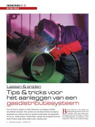
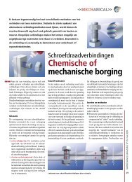
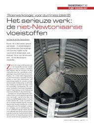
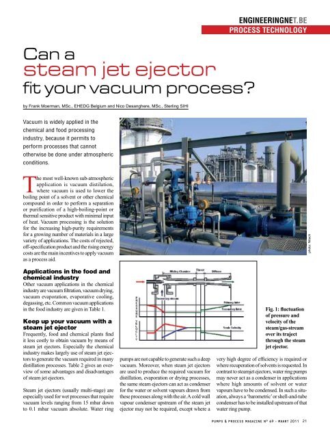
Fig. 1: fluctuation<br />
of pressure and<br />
velocity of the<br />
<strong>steam</strong>/gas-stream<br />
over its traject<br />
through the <strong>steam</strong><br />
<strong>jet</strong> <strong>ejector</strong>.<br />
very high degree of efficiency is required or<br />
where recuperation of solvents is requested. In<br />
contrast to <strong>steam</strong><strong>jet</strong> <strong>ejector</strong>s, water ring pumps<br />
may never act as a condenser in applications<br />
where high amounts of solvent or water<br />
vapours have to be condensed. In such a situation,<br />
always a ‘barometric’ or shell-and-tube<br />
condenser has to be installed upstream of that<br />
water ring pump.<br />
PUMPS & PROCESS MAGAZINE N° 69 - MAARt 2011 21<br />
photo: Nitech
Application Vacuum Absolute<br />
(mbar)<br />
Function<br />
engineeringnet.be<br />
PrOcess tecHNOlOGY<br />
‘Sous-vide’ cooking 50 - 250 To preserve the freshness and nutritional quality of the<br />
minimal processed food.<br />
Evisceration (poultry, fish, etc.) 100 - 150 To remove the bowels.<br />
De-aeration of vegetable oil<br />
50<br />
To remove oxygen that may oxidize unsaturated fatty<br />
acids.<br />
Deodorization of vegetable oil<br />
1 - 3<br />
To strip compounds that affect flavour, odour, stability and<br />
colour from the vegetable oil.<br />
Fractional distillation of vegetable oil<br />
Fractional distillation of essential oils<br />
10<br />
10<br />
To separate fatty acids or their esters from edible oils.<br />
Isolation of flavours and fragrances that otherwise may<br />
decompose and polymerize in the presence of to much<br />
heat.<br />
Freezing drying 20 - 50 Applied to prolong the shelf life of food and to maintain<br />
the basic nutrients in herbs, spices, coffee, fruit, vegetables,<br />
etc.<br />
UHT treatment - vacuum flash cooling of<br />
milk<br />
50 - 100 Milk is heated up to 140-145°C in as few as 3-5 s, contained<br />
in a holding tube for a few seconds, and then fastly<br />
cooled down to 75-80°C due to evaporative cooling as a<br />
consequence of a sudden reduction in pressure.<br />
Vacuum filtration (e.g. yeast) 300 - 600 On a rotary dum dryer a filter cake of yeast can be<br />
sucked dry by means of vacuum.<br />
Vacuum drying 20 - 50 (begin)<br />
1 - 4 (end)<br />
Water evaporates more quickly from food under vacuum.<br />
By vacuum drying, food can become crispy, puffed and<br />
may have a stable colour. Vacuum drying is biologically<br />
desirable since some enzymes that cause oxidation of<br />
food become active during normal air drying. These<br />
enzymes do not appear to be active under vacuum drying<br />
conditions. The speed and the fact that it happens at room<br />
temperature guarantees that taste, colour and nutritional<br />
value of the food are preserved. Also the fibers are fully<br />
preserved, so after reconstitution with water, vacuum dried<br />
fruit and vegetables will reproduce the original texture of<br />
the fresh fruit and vegetables. The drying process can be<br />
accelerated when assisted with micro-wave heating.<br />
Vacuum evaporation of milk 50 To concentrate heat-sensitive products (milk, sugar juices,<br />
etc.) that are prone to discolouration and formation of<br />
cooking favours under the impact of heat.<br />
De-aeration of water 50 Removal of air of the process water used in the preparation<br />
of soft drinks, sparkling and mineral water.<br />
Bottling of beer, soft drinks, mineral and<br />
sparkling water<br />
Vacuum packaging of food in plastic<br />
bags<br />
Modified atmospheric packaging 100<br />
(to remove the air)<br />
50 - 60 Removal of air (oxygen) and dust particles from the bottles<br />
to fill.<br />
100 To remove oxygen that may impair the nutritional quality<br />
by oxidation and that may promote microbial growth of<br />
spoiling bacteria and food pathogens.<br />
In modified atmospheric packaging, the air is first removed<br />
from the packaging by means of vacuum, to be finally<br />
replaced by a modified atmosphere.<br />
Table 1: vacuum applications in the food industry (Note: with vacuum absolute, we allude to the cacuum pressure measure relative to absolute perfect zero vacuum).<br />
How a <strong>steam</strong> <strong>jet</strong> <strong>ejector</strong><br />
works<br />
A <strong>steam</strong> <strong>jet</strong> <strong>ejector</strong> is in fact based on the<br />
principles of a water aspirator, that produces<br />
a vacuum by means of a venturi-effect and<br />
which is the oldest known method of vacuum<br />
generation. In a <strong>steam</strong> <strong>jet</strong> <strong>ejector</strong>, however, the<br />
water is replaced by <strong>steam</strong> as motive fluid.<br />
The motive <strong>steam</strong> fluid is expanded, after<br />
passing through a motive nozzle, where the<br />
pressure energy is transformed into kinetic<br />
energy. This energy stream impinges with<br />
and withdraws gases, air and water vapour<br />
from an application where a sub-atmospheric<br />
pressure (vacuum) must be established or<br />
maintained. The <strong>steam</strong> vapour accelerates into<br />
the inlet cone of the mixing nozzle. After passing<br />
through the throat of the mixing nozzle,<br />
into the diffuser, the kinetic energy of the<br />
mixed vapour stream is gradually converted<br />
back into potential energy, i.e. the medium is<br />
PUMPS & PROCESS MAGAZINE N° 69 - MAARt 2011 23
engineeringnet.be<br />
PrOcess tecHNOlOGY<br />
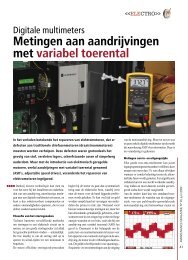
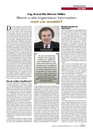
Fig. 2: three-stage <strong>steam</strong> <strong>jet</strong> <strong>ejector</strong> with<br />
two barometric intercondensers and one<br />
barometric aftercondenser.<br />
compressed to a higher discharge pressure.<br />
Fig. 1 demonstrates how the pressure and<br />
24<br />
Steam-<strong>jet</strong><br />
type<br />
1-stage<br />
2-stage<br />
3-stage<br />
4-stage<br />
Max.<br />
absolute<br />
vacuum<br />
(mbar)<br />
66<br />
5-15<br />
1-1.5<br />
0.1-0.3<br />
PUMPS & PROCESS MAGAZINE N° 69 - MAARt 2011<br />
velocity of the <strong>steam</strong>/<br />
gas-stream fluctuates<br />
over its traject through<br />
the <strong>steam</strong> <strong>jet</strong> <strong>ejector</strong>.<br />
Basic<br />
components<br />
of a <strong>steam</strong> <strong>jet</strong><br />
<strong>ejector</strong><br />
A single stage <strong>steam</strong><br />
<strong>ejector</strong> can produce<br />
only a limited vacuum<br />
(cfr. Table 2). Multistage<br />
<strong>steam</strong> <strong>ejector</strong>s<br />
(Fig. 2) are used when<br />
an application requires<br />
a pressure lower than<br />
what single-stage <strong>ejector</strong>s<br />
can develop, as the<br />
first can develop a greater suction pressure.<br />
With more stages added to the system, the<br />
pressure of the first stage becomes lesser<br />
and lesser, generating a deeper vacuum. The<br />
<strong>ejector</strong> which the entrained gases enter first,<br />
is called the first stage and subsequent stages<br />
Advantages Disadvantages<br />
- High achievable vacuum<br />
- High suction capacities and gas flow<br />
- Controlable over a wide range of vacuum<br />
and flow rates<br />
- Excellent to handle condensable corrosive<br />
and contaminated loads<br />
- Excellent to handle liquid slugs and solid<br />
particles<br />
- Reliable and robust in arduous and<br />
corrosive conditions<br />
- Simple design<br />
- Designed in many materials of construction<br />
- Mountable in any position<br />
- Low investment cost<br />
- No moving parts, less failure risk<br />
- Less susceptible to wear, and trouble-freeoperation<br />
- Long life-span<br />
- Simple repair & maintenance<br />
- No heat emission<br />
Table 2: advantages and disadvantages of <strong>steam</strong> <strong>jet</strong> <strong>ejector</strong>s.<br />
are numbered in succession.<br />
It is desirable to connect a condenser to<br />
the discharge of each <strong>steam</strong> <strong>jet</strong> <strong>ejector</strong> to<br />
bring all <strong>steam</strong> and condensable gases to<br />
the liquid state, reducing the load to the succeeding<br />
<strong>ejector</strong> stage and thus imposing on<br />
subsequent stages the work of compressing<br />
only those gases that are non-condensable.<br />
The condensers so em-ployed are known as<br />
intercondensers. A condenser connected to the<br />
diffuser dis-charge of the final stage is known<br />
as an aftercondenser, that is used to prevent the<br />
discharge of motive <strong>steam</strong> and condensable<br />
process vapours into atmosphere.<br />
An intercondenser operates at pressures<br />
less than atmospheric (under vacuum). It<br />
is therefore necessary to provide means for<br />
draining the mixture of condensing water<br />
and condensed <strong>steam</strong>/condensable vapours<br />
from a barometric intercondenser, or the<br />
condensed <strong>steam</strong>/condensable vapours only<br />
from a shell-and-tube inter-condenser. The<br />
non-condensable vapours are withdrawn from<br />
the top of each intercondenser by the vacuum<br />
of the subsequent <strong>steam</strong> <strong>ejector</strong>. The after-<br />
- Consumption of large amounts of <strong>steam</strong> as<br />
pressurized motive fluid<br />
- High energy consumption<br />
- Low thermal efficiency<br />
- Requires a <strong>steam</strong> infrastructure<br />
- Need for high quality <strong>steam</strong> produced from<br />
soft-demineralised water<br />
- Steam must be dry or should have less than<br />
2% moisture, because wet <strong>steam</strong> may cause<br />
the <strong>ejector</strong> vacuum to break or fluctuate, and<br />
can erode the nozzle and diffusers.<br />
- Needs inter-condensers and after-condensed<br />
and large amounts of cooling fluid to<br />
condense the mixture of motive and process<br />
vapour<br />
- Contamination of the motive fluid<br />
- Large amounts of contaminated <strong>steam</strong> condensate<br />
(waste water)<br />
- Load specific and very sensitive to variations<br />
in process conditions and pressure<br />
- Noisy, requires silencers or sound insulation
condenser operates at atmospheric<br />
pressure and is provided<br />
with a vent to finally allow air<br />
and non-condensable gases to<br />
escape in the atmosphere.<br />
‘Barometric’<br />
condensers<br />
A ‘barometric condenser’ (also<br />
called direct contact condenser)<br />
is a vertical vessel where<br />
withdrawn process vapours are<br />
cooled and condensed by direct<br />
contact with downward flowing<br />
cold water injected into the top<br />
of the vessel. Since the operating<br />
pressure of the condenser<br />
is sub-atmospheric (under<br />
vacuum), collected condensate<br />
(effluent cooling water and condensed <strong>steam</strong>/<br />
vapours) must be continuously removed. That<br />
condensate is normally dropped into a receiver<br />
tank that is often vented to atmosphere<br />
or a low pressure vent system. This creates<br />
a situation where the condensate is under<br />
vacuum in the condenser and is trying to<br />
move toward the receiver tank that is under<br />
positive pressure. To overcome this pressure<br />
differential, the condenser must be located<br />
higher than the receiver tank (the bottom of<br />
the condenser should be at least 10.4 meters<br />
above the ground) to create a tall ‘barometric<br />
leg’ (10.4 m long pipe) in which a static<br />
column of liquid balances the atmospheric<br />
pressure. The condensate must flow by gravity<br />
through this long sealed vertical tail pipe into<br />
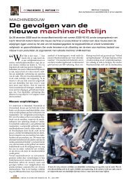
Fig. 3: if tail pipe must change in direction,<br />
it should form at least a 45° angle<br />
from the horizontal plane; the horizontal<br />
piping (right drawing) is vulnerable to<br />
gas accumulation.<br />
a ‘hot-well’ (drainage basin provided with an<br />
overflow or pump) or a sealed condensate tank<br />
(provided with fluid-level control and condensate<br />
pump). The ‘barometric leg’ allows the<br />
effluent coolant and condensed vapours in the<br />
barometric condenser to exit no matter what<br />
its vacuum is, finally preventing the condenser<br />
from flooding under normal operation.<br />
In the receiver tank, the tail pipe must be<br />
submerged enough (not less than 28 cm). If<br />
this seal is broken, air will be drawn into the<br />
engineeringnet.be<br />
PrOcess tecHNOlOGY<br />
tailpipe, increasing the risk<br />
for flooding the condenser<br />
and hence affecting the<br />
performance of the downstream<br />
vacuum source and<br />
the upstream vacuum process.<br />
The drainage lines or<br />
tailpipes should be preferably<br />
installed vertically.<br />
Horizontal drain leg runs are<br />
not recommended, because<br />
they are susceptible to gas<br />
pockets. The mixture of<br />
cooling water plus condensed<br />
<strong>steam</strong>/condensable<br />
vapours always contain air<br />
or other non-condensable<br />
gases which cling to upper<br />
pipe surfaces. All types of<br />
pipe contain a certain amount of internal<br />
roughness and, because of this, gases tend to<br />
start clinging and building up in the smallest<br />
crevice. In addition, every flanged joint has<br />
a slight crack where a gasket is located, thus<br />
permitting another place for gases to collect.<br />
As these gases accumulate, they form tiny<br />
bubbles, growing into larger ones that eventually<br />
become big enough to partially or completely<br />
block off piping at that point. In that<br />
case, the condensate cannot flow downwards<br />
and soon its level rises, flooding the condenser.<br />
If piping changes direction, it must form at<br />
least a 45° angle from the horizontal (Fig. 3).<br />
With this amount of sloping, gases will either<br />
slide back up the pipe or continue downward<br />
with the thrust of the flowing water. The 45°<br />
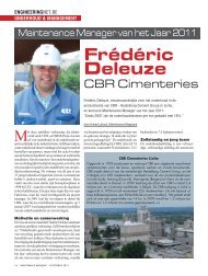
Fig. 4: (a) with barometric condensers, it is important to note that condensate is splashing down the barometric walls and could run<br />
down the vapour inlet and back into the upstream vacuum process, unless the inlet is protected by a dam or series of elbows; (b)<br />
Degradation of the absolute vacuum pressure of an upstream process due to the pooling of liquid in pockets located in the vapour<br />
inlet or outlet piping. Pocket-free designs, however, may maintain the required absolute vacuum pressures.<br />
PUMPS & PROCESS MAGAZINE N° 69 - MAARt 2011 25
end may only installed at no less than 5 pipe diameters away from the<br />
condenser outlet flange. Where there is insufficient height to construct<br />
a proper barometric leg, a low-level, condensate-removal system can<br />
be added. This consists of a receiver equipped with a level controller<br />
and a condensate pump. As a condensate pump removes condensate at<br />
a constant rate, a mechanical level controller opens and closes a valve,<br />
to control the flow of cooling water to the condenser. However, if either<br />
pump or controller fails, there is a risk of flooding the vacuum system.<br />
Direct-contact condensers are easily to design, relatively inexpensive,<br />
and make multi-stage <strong>steam</strong> <strong>jet</strong> <strong>ejector</strong> designs less vulnerable to<br />
damage or fouling resulting from carryover of entrained solids. The<br />
major disadvantage of direct contact condensers is the large quantity<br />
of water that passes through once and goes to disposal, increasing the<br />
cost of wastewater and the environmental impact.<br />
Shell-and-tube condensers<br />
Surface-type condensers (that can be provided with supplementary<br />
mechanical refrigeration) are more complex and more expensive;<br />
but the amount of waste water to be treated decreases and valuable<br />
compounds can be recycled. In the case that a shell-and-tube surface<br />
condenser is used, this condenser must also be installed to allow for<br />
complete condensate drainage. The condensate may not flood the<br />
lower tubes of the condenser, otherwise they will not be able to remove<br />
heat effectively.<br />
Measures to protect the upstream process<br />
With barometric condensers, it is important to note that condensate is<br />
splashing down the barometric walls and could run down the vapour<br />
inlet and back into the vacuum process equipment, unless the inlet is<br />
protected by a dam or series of elbows (Fig. 4a).<br />
Condensable vapours flowing in the inlet or outlet vapour pipeline will<br />
naturally condense since the pipe is usually cooler than the saturation<br />
temperature of the vapour it contains. Vapour piping entering and<br />
leaving a barometric condenser (or a shell-and-tube condenser) may<br />
not contain any pockets (Fig. 4b) where this liquid can accumulate.<br />
The liquid pooling in these pockets, will completely seal off the line,<br />
which finally results in a downgrading of the vacuum. The absolute<br />
vacuum pressure up-stream of a pocket will rise dramatically.