Curved Beam - VTU e-Learning
Curved Beam - VTU e-Learning
Curved Beam - VTU e-Learning

Create successful ePaper yourself
Turn your PDF publications into a flip-book with our unique Google optimized e-Paper software.
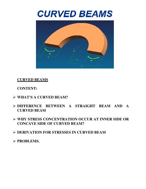
CURVED BEAMS<br />
CONTENT:<br />
WHAT’S A CURVED BEAM BEAM?<br />
DIFFERENCE BETWEEN A STRAIGHT BEAM AND A<br />
CURVED BEAM<br />
WHY STRESS CONCENTRA<br />
CONCENTRATION TION OCCUR AT INNER SIDE OR<br />
CONCAVE SIDE OF CURV CURVED BEAM?<br />
DERIVATION FOR STRES STRESSES IN CURVED BEAM<br />
PROBLEMS.
Theory of Simple Bending<br />
Due to bending moment, tensile stress develops in one portion of section<br />
and compressive stress in the other portion across the depth. In between<br />
these two portions, there is a layer where stresses are zero. Such a layer<br />
is called neutral layer. Its trace on the cross section is called neutral axis.<br />
Assumption<br />
The material of the beam is perfectly homogeneous and isotropic.<br />
The cross section has an axis of symmetry in a plane along the<br />
length of the beam.<br />
The material of the beam obeys Hooke’s law.<br />
The transverse sections which are plane before bending remain<br />
plane after bending also.<br />
Each layer of the beam is free to expand or contract, independent of<br />
the layer above or below it.<br />
Young’s modulus is same in tension & compression.<br />
Consider a portion of beam between sections AB and CD as shown in<br />
the figure.<br />
Let e1f1 be the neutral axis and g1h1 an<br />
element at a distance y from neutral<br />
axis. Figure shows the same portion<br />
after bending. Let r be the<br />
radius of curvature and ѳ is the angle<br />
subtended by a1b1 and c1d1at centre of<br />
radius of curvature. Since it is a neutral<br />
axis, there is no change in its length (at<br />
neutral axis stresses are zero.)<br />
EF = E1F1 = RѲ
G1H1 = (R+Y) Ѳ<br />
Also Stress<br />
OR<br />
dF = 0<br />
GH = RRѲ<br />
∴ there is no direct force acting on the element considered.
Since Σyδa a is first moment of area about neutral axis, Σyδa/a Σ is the<br />
distance of centroid from neutral axis. Thus neutral axis coincides with<br />
centroid of the cross section. Cross sec sectional tional area coincides with neutral<br />
axis.<br />
From (1) and (2)<br />
CURVED BEAM<br />
<strong>Curved</strong> beams are the parts of machine members found in C -<br />
clamps, crane hooks, frames of presses, riveters, punches, shears, boring<br />
machines, planers etc. In straight beams the neutral axis of the section<br />
coincides with its centroidal axis and the stress distribution in the beam<br />
is linear. But in the case of curved beams the neutral axis of the section<br />
is shifted towards the centre of curvature of the beam causing a nonlinear<br />
[hyperbolic] distribution of stress. The neutral axis lies between<br />
the centroidal axis and the centre of curvature and will always be present<br />
within the curved beams.
Stresses in <strong>Curved</strong> <strong>Beam</strong><br />
Consider a curved beam subjected to bending moment Mb as shown<br />
in the figure. The distribution of stress in curved flexural member is<br />
determined by using the following assumptions:<br />
i) The material of the beam is perfectly homogeneous [i.e., same<br />
material throughout] and isotropic [i.e., equal elastic properties in all<br />
directions]<br />
ii) The cross section has an axis of symmetry in a plane along the length<br />
of the beam.<br />
iii) The material of the beam obeys Hooke's law.<br />
iv) The transverse sections which are plane before bending remain plane<br />
after bending also.<br />
v) Each layer of the beam is free to expand or contract, independent of<br />
the layer above or below it.<br />
vi) The Young's modulus is same both in tension and compression.<br />
Derivation for stresses in curved beam<br />
Nomenclature used in curved beam<br />
Ci =Distance from neutral axis to inner radius of curved beam<br />
Co=Distance from neutral axis to outer radius of curved beam<br />
C1=Distance from centroidal axis to inner radius of curved beam<br />
C2= Distance from centroidal axis to outer radius of curved beam<br />
F = Applied load or Force<br />
A = Area of cross section<br />
L = Distance from force to centroidal axis at critical section<br />
σd= Direct stress<br />
σbi = Bending stress at the inner fiber<br />
σbo = Bending stress at the outer fiber<br />
σri = Combined stress at the inner fiber<br />
σro = Combined stress at the outer fiber
Stresses in curved beam<br />
Mb = Applied Bending Moment<br />
ri = Inner radius of curved beam<br />
ro = Outer radius of curved beam<br />
rc = Radius of centroidal axis<br />
rn = Radius of neutral axis<br />
CL = Center of curvature<br />
M b<br />
F<br />
F<br />
In the above figure the lines 'ab' and 'cd' represent two such planes<br />
before bending. i.e., when there are no stresses induced. When a bending<br />
moment 'Mb' ' is applied to the beam the plane cd rotates with respect to<br />
'ab' through an angle 'd 'dθ' ' to the position 'fg' and the outer fibers are<br />
shortened while the inner fibers s are elongated. The original length of a<br />
strip at a distance 'y' from the neutral axis is (y + rrn)θ.<br />
It is shortened by<br />
the amount ydθ and the stress in this fiber is,<br />
NA c 2<br />
CA<br />
σ = E.e<br />
Where σ = stress, e = strain and E = Young's Modulus<br />
c 1<br />
C L<br />
c i c o<br />
r i<br />
e<br />
r n<br />
r c<br />
r o<br />
F<br />
F<br />
M b
We know, stress σ = E.e<br />
We know, stress e <br />
<br />
<br />
i.e., σ = – E θ<br />
θ<br />
Ѳ<br />
Ѳ<br />
..... (i)<br />
Since the fiber is shortened, the stress induced in this fiber is<br />
compressive stress and hence negative sign.<br />
The load on the strip having thickness dy and cross sectional area dA is<br />
'dF'<br />
i.e., dF = σdA = – θ<br />
θ dA<br />
From the condition of equilibrium, the summation of forces over the<br />
whole cross-section is zero and the summation of the moments due to<br />
these forces is equal to the applied bending moment.<br />
Let<br />
M b = Applied Bending Moment<br />
r i = Inner radius of curved beam<br />
r o = Outer radius of curved beam
c = Radius of centroidal axis<br />
r n = Radius of neutral axis<br />
CL= Centre line of curvature<br />
Summation of forces over the whole cross section<br />
i.e. dF 0<br />
As θ<br />
θ<br />
∴ θ<br />
θ<br />
<br />
=0<br />
is not equal to zero,<br />
∴ <br />
<br />
= 0 ..... (ii)<br />
The neutral axis radius 'rn' can be determined from the above equation.<br />
If the moments are taken about the neutral axis,<br />
M b = – ydF<br />
Substituting the value of dF, we get<br />
M b = θ<br />
θ<br />
<br />
dA<br />
= θ<br />
θ y dA<br />
= θ<br />
θ<br />
ydA <br />
<br />
0<br />
Since ydA represents the statical moment of area, it may be replaced<br />
by A.e., the product of total area A and the distance 'e' from the<br />
centroidal axis to the neutral axis.
∴ M = b θ<br />
A.e ..... (iii)<br />
θ<br />
From equation (i) θ<br />
θ = – σ <br />
Substituting in equation (iii)<br />
M = – b σ . A. e.<br />
<br />
∴ σ = <br />
<br />
..... (iv)<br />
This is the general equation for the stress in a fiber at a distance 'y' from<br />
neutral axis.<br />
At the outer fiber, y = co<br />
∴ Bending stress at the outer fiber σbo i.e., σ = bo ( rn + co = ro) ..... (v)<br />
Where co = Distance from neutral axis to outer fiber. It is compressive<br />
stress and hence negative sign. At the inner fiber, y = – ci<br />
∴ Bending stress at the inner fiber<br />
σ bi = <br />
<br />
i.e., σ bi = <br />
<br />
( rn – ci = ri) ..... (vi)<br />
Where ci = Distance from neutral axis to inner fiber. It is tensile stress<br />
and hence positive sign.
Difference between a straight beam and a curved beam<br />
Sl.no straight beam curved beam<br />
1 In Straight beams the neutral<br />
axis of the section coincides<br />
with its centroidal axis and the<br />
stress distribution in the beam<br />
is linear.<br />
In case of curved beams the<br />
neutral axis of the section is<br />
shifted towards the center of<br />
curvature of the beam causing<br />
a non-linear stress<br />
distribution.
2<br />
3 Neutral axis and centroidal<br />
axis coincides<br />
Neutral axis is shifted<br />
towards the least centre of<br />
curvature<br />
Location of the neutral axis By considering a rectangular cross<br />
section
Centroidal and Neutral Axis of Typical Section of <strong>Curved</strong> <strong>Beam</strong>s
Why stress concentration occur at inner side or concave side of<br />
curved beam<br />
Consider the elements of the curved beam lying between two axial<br />
planes ‘ab’ and ‘cd’ separated by angle θ. . Let fg is the final position of<br />
the plane cd having rotated through an angle ddθ<br />
about neutral axis.<br />
Consider two fibers symmetrically located on either side of the neutral<br />
axis. Deformation in both the fibers is same and equal to yd ydθ θ.
Since length of inner element is smaller than outer element, the strain<br />
induced and stress developed are higher for inner element than outer<br />
element as shown.<br />
Thus stress concentration occur at inner side or concave side of curved<br />
beam<br />
The actual magnitude of stress in the curved beam would be influenced<br />
by magnitude of curvature However, for a general comparison the stress<br />
distribution for the same section and same bending moment for the<br />
straight beam and the curved beam are shown in figure.<br />
It is observed that the neutral axis shifts inwards for the curved beam.<br />
This results in stress to be zero at this position, rather than at the centre<br />
of gravity.<br />
In cases where holes and discontinuities are provided in the beam, they<br />
should be preferably placed at the neutral axis, rather than that at the<br />
centroidal axis. This results in a better stress distribution.<br />
Example:<br />
For numerical analysis, consider the depth of the section ass twice<br />
the inner radius.
For a straight beam:<br />
Inner most fiber:<br />
Outer most fiber:<br />
For curved beam: h=2r h=2ri<br />
e = rc - rn = h – 0.910h = 0.0898h<br />
co = ro - rn= h – 0.910h = 0590h<br />
ci = rn - ri = 0.910h -<br />
= 0.410h
Comparing the stresses at the inner most fiber based on (1) and (3), we<br />
observe that the stress at the inner most fiber in this case is:<br />
σbci = 1.522σBSi<br />
Thus the stress at the inner most fiber for this case is 1.522 times greater<br />
than that for a straight beam.<br />
From the stress distribution it is observed that the maximum stress in a<br />
curved beam is higher than the straight beam.<br />
Comparing the stresses at the outer most fiber based on (2) and (4), we<br />
observe that the stress at the outer most fiber in this case is:<br />
σbco = 1.522σBSi<br />
Thus the stress at the inner most fiber for this case is 0.730 times that for<br />
a straight beam.<br />
The curvatures thus introduce a non linear stress distribution.<br />
This is due to the change in force flow lines, resulting in stress<br />
concentration on the inner side.<br />
To achieve a better stress distribution, section where the centroidal axis<br />
is the shifted towards the insides must be chosen, this tends to equalize<br />
the stress variation on the inside and outside fibers for a curved beam.<br />
Such sections are trapeziums, non symmetrical I section, and T sections.<br />
It should be noted that these sections should always be placed in a<br />
manner such that the centroidal axis is inwards.<br />
Problem no.1<br />
Plot the stress distribution about section A-B of the hook as shown in<br />
figure.<br />
Given data:<br />
ri = 50mm<br />
ro = 150mm<br />
F = 22X10 3 N<br />
b = 20mm<br />
h = 150-50 = 100mm<br />
A = bh = 20X100 = 2000mm 2
e = rc - rn = 100 - 91.024 = 8.976mm<br />
Section A-B B will be subjected to a combination of direct load and<br />
bending, due to the eccentricity of the force.<br />
Stress due to direct load will be,<br />
y = rn – r = 91.024 – r<br />
Mb = 22X10 3 X100 = 2.2X10 6 N-mm
Problem no.2<br />
Determine the value of “t” in the cross section of a curved beam as<br />
shown in fig such that the normal stress due to bending at the extreme<br />
fibers are numerically equal.<br />
Given data;<br />
Inner radius ri=150mm =150mm<br />
Outer radius ro=150+40+100<br />
=150+40+100<br />
=290mm<br />
Solution;<br />
From Figure Ci + CO = 40 + 100<br />
= 140mm…………… (1)<br />
Since the normal stresses due to bending at<br />
the extreme fiber are numerically equal we<br />
have,<br />
i.e Ci=<br />
Radius of neutral axis<br />
rn=<br />
= 0.51724C 0.51724Co…………… (2)<br />
rn =197.727 mm<br />
ai = 40mm; bi = 100mm; bb2<br />
=t;<br />
ao = 0; bo = 0; ri = 150mm; rro<br />
= 290mm;
=<br />
i.e., 4674.069+83.61t +83.61t = 4000+100t;<br />
∴ t = 41.126mm<br />
Problem no.3<br />
Determine the stresses at point A and B of the split ring shown in the<br />
figure.<br />
Solution:<br />
The figure shows the critical section of the split<br />
ring.<br />
Radius of centroidal axis rc = 80mm<br />
Inner radius of curved beam ri = 80<br />
Outer radius of curved beam ro = 80 +<br />
Radius of neutral axis<br />
Applied force<br />
= 50mm<br />
= 110mm<br />
rn =<br />
=<br />
= 77.081mm<br />
F = 20kN = 20,000N (compressive)
Area of cross section A = π<br />
d2 = π<br />
x602 = 2827.433mm 2<br />
Distance from centroidal axis to force l = rc = 80mm<br />
Bending moment about centroidal axis Mb = Fl = 20,000x80<br />
=16x10 5 N-mm<br />
Distance of neutral axis to centroidal axis<br />
e = rc rn<br />
= 80 77.081=2.919mm<br />
Distance of neutral axis to inner radius<br />
ci = rn ri<br />
= 77.081 50=27.081mm<br />
Distance of neutral axis to outer radius<br />
Direct stress σd = <br />
co = ro rn<br />
= 110 77.081=32.919mm<br />
<br />
= <br />
.<br />
= 7.0736N/mm 2 (comp.)<br />
Bending stress at the inner fiber σbi = <br />
<br />
= .<br />
..<br />
Bending stress at the outer fiber σbo = =<br />
Combined stress at the inner fiber<br />
= 105N/mm 2 (compressive)<br />
<br />
.<br />
..<br />
= 58.016N/mm 2 (tensile)
σri = σd + σbi<br />
= 7.0736 105.00<br />
= - 112.0736N/mm 2 (compressive)<br />
Combined stress at the outer fiber<br />
σro = σd + σbo<br />
= 7.0736+58.016<br />
= 50.9424N/mm 2 (tensile)<br />
Maximum shear stress<br />
The figure.<br />
τmax = 0.5x σmax<br />
= 0.5x112.0736<br />
= 56.0368N/mm 2 , at B
Problem No. 4<br />
<strong>Curved</strong> bar of rectangular section 40x60mm and a mean radius of<br />
100mm is subjected to a bending moment of 2KN 2KN-m m tending to<br />
straighten the bar. Find the position of the Neutral axis and draw a<br />
diagram to show the variation of stress across the section.<br />
Solution<br />
Given data:<br />
b= 40mm h= 60mm<br />
rc=100mm Mb= = 2x10<br />
C1=C2= 30mm<br />
6 N-mm<br />
30mm<br />
rn=<br />
ro= rc+h/2=100+30=130 =130 =(r =(ri+c1+c2)<br />
ri= rc- h/2 = 100 - 30= 70mm (rc-c1)<br />
rn= 96.924mm<br />
Distance of neutral axis to centroidal axis<br />
e = rc - rn= 100-96.924<br />
=3.075mm<br />
Distance of neutral axis to inner radius<br />
ci= rn- ri = (c1-e) = 26.925mm<br />
Distance of neutral axis to outer radius<br />
co=c2+e= (ro-rn) = 33.075mm<br />
Area<br />
A= bxh = 40x60 = 2400 mm 2<br />
e) = 26.925mm<br />
) = 33.075mm<br />
Bending stress at the inner fiber σbi = =<br />
= 104.239 N/mm 2 (compressive)
Bending stress at the outer fiber σbo = =<br />
. .<br />
= -68.94 N/mm 2 (tensile)<br />
Bending stress at the centroidal axis = <br />
<br />
= <br />
<br />
= -8.33 N/mm 2 (Compressive)<br />
The stress distribution at the inner and outer fiber is as shown in the<br />
figure.
Problem No. 5<br />
The section of a crane hook is a trapezium; the inner face is b and is at a<br />
distance of 120mm from the centre line of curvature. The outer face is<br />
25mm and depth of trapezium =120mm.Find the proper value of b, if the<br />
extreme fiber stresses due to pure bending are numerically equal, if the<br />
section is subjected to a couple which develop a maximum fiber stress of<br />
60Mpa.Determine the magnitude of the couple.<br />
Solution<br />
ri = 120mm; bi = b; bo= 25mm; h = 120mm<br />
σbi = σbo = 60MPa<br />
Since the extreme fibers stresses due to pure bending are numerically<br />
equal we have,<br />
We have,<br />
But h= ci + co<br />
120 = ci+2ci<br />
<br />
<br />
= <br />
<br />
Ci/ri =co/ro =ci/co =120/240<br />
2ci=co<br />
Ci=40mm; co=80mm<br />
rn= ri + ci = 120+40 =160 mm
=150.34mm<br />
To find the centroidal axis, (C2)<br />
bo= 125.84mm; b=25mm; h=120mm<br />
= 74.313mm.<br />
But C1=C2<br />
rc= ro-c2 =240 - 74.313 =165.687mm<br />
e=rc- rn = 165.687 - 160 = 5.6869 mm<br />
Bending stress in the outer fiber,<br />
σ M c <br />
Aer <br />
A= .<br />
<br />
= 1050.4mm<br />
60 =<br />
<br />
..<br />
Mb=10.8x10 6 N-mm
Problem no.6<br />
Determine the stresses at point A and B of the split ring shown in<br />
fig.1.9a<br />
Solution:<br />
Redraw the critical section as shown in the figure.<br />
Radius of centroidal axis rc = 80mm<br />
Inner radius of curved beam ri = 80 <br />
Outer radius of curved beam ro = 80 + <br />
Radius of neutral axis rn = <br />
<br />
= √√<br />
<br />
<br />
<br />
= 50mm<br />
= 110mm<br />
=77.081mm<br />
Applied force F = 20kN = 20,000N (compressive)<br />
Area of cross section A = π<br />
d2 = π<br />
x602 = 2827.433mm 2<br />
Distance from centroidal axis to force l = rc = 80mm<br />
Bending moment about centroidal axis Mb = FI = 20,000x80<br />
=16x10 5 N-mm<br />
Distance of neutral axis to centroidal axis e = rc rn<br />
= 80 77.081<br />
=2.919mm
Distance of neutral axis to inner radius<br />
ci = rn ri = 77.081 50 = 27.081mm<br />
Distance of neutral axis to outer radius<br />
co = ro rn = 110 77.081 = 32.919mm<br />
Direct stress σd = <br />
<br />
= <br />
.<br />
= 7.0736N/mm 2 (comp.)<br />
Bending stress at the inner fiber σbi = <br />
<br />
Bending stress at the outer fiber σbo = <br />
<br />
Combined stress at the inner fiber<br />
σri = σd + σbi = 7.0736 105.00<br />
= .<br />
..<br />
= 105N/mm 2 (compressive)<br />
=<br />
.<br />
..<br />
= 58.016N/mm 2 (tensile)<br />
= 112.0736N/mm 2 (compressive)<br />
Combined stress at the outer fiber<br />
σro = σd + σb = 7.0736+58.016<br />
Maximum shear stress<br />
= 50.9424N/mm 2 (tensile)<br />
max = 0.5x σmax = 0.5x112.0736<br />
= 56.0368N/mm 2 , at B
The figure shows the stress distribution in the critical section.
Problem no.7<br />
Determine the maximum tensile, compressive and shear stress induced<br />
in a ‘c’ frame of a hydraulic portable riveter shown in fig.1.6a<br />
Solution:<br />
Draw the critical section as shown in<br />
the figure.<br />
80<br />
Inner radius of curved beam ri =<br />
100mm<br />
Outer radius of curved beam ro = 100+80<br />
= 180mm<br />
Radius of centroidal axis rc = 100+ <br />
= 140mm<br />
Radius of neutral axis rn = ln <br />
<br />
<br />
= ln <br />
<br />
<br />
50<br />
<br />
= 136.1038mm<br />
Distance of neutral axis to centroidal axis<br />
e = rc - rn = 140-136.1038 = 3.8962mm<br />
Critical<br />
Section<br />
R100<br />
b = 50 mm<br />
175 mm<br />
c 2<br />
c o<br />
h = 80mm<br />
e<br />
CA<br />
NA<br />
r o<br />
9000N<br />
c 1<br />
c i<br />
rn rc r = 100mm<br />
i<br />
C L<br />
175mm<br />
F<br />
F
Distance of neutral axis to inner radius<br />
ci = rn - ri = 136.1038-100 = 36.1038mm<br />
Distance of neutral axis to outer radius<br />
co = ro - rn = 180-136.1038 = 43.8962mm<br />
Distance from centroidal axis to force<br />
Applied force F = 9000N<br />
l = 175+ rc = 175+140 = 315mm<br />
Area of cross section A = 50x80 = 4000mm 2<br />
Bending moment about centroidal axis Mb = FI = 9000x315<br />
Direct stress σd = <br />
<br />
= 2835000 N-mm<br />
= <br />
= 2.25N/mm2 (tensile)<br />
Bending stress at the inner fiber σbi = <br />
<br />
Bending stress at the outer fiber σbo = <br />
= .<br />
.<br />
= 65.676N/mm 2 (tensile)<br />
<br />
= .<br />
.<br />
= 44.326N/mm 2 (compressive)<br />
Combined stress at the inner fiber σri = σd + σbi = 2.25+65.676<br />
= 67.926N/mm 2 (tensile)<br />
Combined stress at the outer fiber σro = σd + σbo = 2.25 44.362<br />
= 42.112 N/mm 2 (compressive)
Maximum shear stress max = 0.5x σmax = 0.5x67.926<br />
= 33.963 N/mm 2 , at the inner fiber<br />
The stress distribution on the critical section is as shown in the figure.<br />
Combined stress = -42.112 N/mm<br />
σ ro<br />
2<br />
Bending stress σbo=-44.362 N/mm<br />
Direct stress ( σd) 2<br />
CA<br />
NA<br />
h =80 mm<br />
σ ri=67.926 N/mm 2<br />
σ bi=65.676 N/mm 2<br />
σ d=2.25 N/mm 2<br />
b = 50 mm
Problem no.8<br />
The frame punch press is shown in fig. 1.7s. Find the stress in inner and<br />
outer surface at section A-B the frame if F = 5000N<br />
Solution:<br />
Draw the critical section as shown in the<br />
figure.<br />
Inner radius of curved beam ri = 25mm<br />
Outer radius of curved beam ro = 25+40<br />
= 65mm<br />
Distance of centroidal axis from inner fiber c1 = <br />
= <br />
<br />
<br />
b = 6 mm<br />
o<br />
c 2<br />
c o<br />
<br />
<br />
= 16.667mm<br />
h = 40mm<br />
e<br />
CA<br />
NA<br />
<br />
r o<br />
c 1<br />
c i<br />
r c<br />
r n<br />
b = 18 mm<br />
i<br />
r = 25mm<br />
i<br />
C L<br />
100mm<br />
F<br />
F
∴ Radius of centroidal axis rc = ri c1<br />
Radius of neutral axis rn =<br />
= 25+16.667 = 41.667 mm<br />
=<br />
<br />
<br />
<br />
<br />
<br />
<br />
<br />
<br />
<br />
<br />
Distance of neutral axis to centroidal axis e = rc rn<br />
Distance of neutral axis to inner radius ci = rn ri<br />
Distance of neutral axis to outer radius co = ro rn<br />
=38.8175mm<br />
<br />
<br />
= 1.66738.8175<br />
=2.8495mm<br />
= 38.817525=13.8175mm<br />
= 65-38.8175=26.1825mm<br />
Distance from centroidal axis to force l = 100+ rc = 100+41.667<br />
Applied force F = 5000N<br />
Area of cross section A = <br />
b b = <br />
<br />
= 141.667mm<br />
x4018 6 = 480mm2<br />
Bending moment about centroidal axis Mb = FI = 5000x141.667<br />
= 708335 N-mm
Direct stress σd = <br />
<br />
= <br />
= 10.417N/mm2 (tensile)<br />
Bending stress at the inner fiber σbi = <br />
<br />
Bending stress at the outer fiber σbo = <br />
<br />
= .<br />
.<br />
= 286.232N/mm 2 (tensile)<br />
= .<br />
.<br />
= 208.606N/mm 2 (compressive)<br />
Combined stress at the inner fiber σri = σd + σbi = 10.417+286.232<br />
= 296.649N/mm 2 (tensile)<br />
Combined stress at the outer fiber σro = σd + σbo = 10.417286.232<br />
= 198.189N/mm 2 (compressive)<br />
Maximum shear stress max = 0.5x σmax = 0.5x296.649<br />
= 148.3245 N/mm 2 , at the inner fiber<br />
The figure shows the stress distribution in the critical section.
Combined stress =-198.189 N/mm<br />
σ ro<br />
2<br />
Bending stress σbo=-208.606 N/mm<br />
Direct stress (σ d)<br />
b = 6 mm<br />
o<br />
2<br />
CA<br />
NA<br />
h =40 mm<br />
σ ri=296.649 N/mm 2<br />
σ bi=286.232 N/mm 2<br />
σ d=10.417 N/mm 2<br />
b = 18 mm<br />
i
Problem no.9<br />
Figure shows a frame of a punching machine and its various dimensions.<br />
Determine the maximum stress in the frame, if it has to resist a force of<br />
85kN<br />
Solution:<br />
Draw the critical section as shown in the<br />
figure.<br />
Inner radius of curved beam ri = 250mm<br />
Outer radius of curved beam ro = 550mm<br />
Radius of neutral axis<br />
rn =<br />
<br />
<br />
<br />
<br />
<br />
ai = 75mm; bi = 300mm; b2 = 75mm; ao = 0; bo = 0<br />
A=a1+a2=75x300+75x225 =39375mm 2<br />
∴ rn =<br />
75<br />
Let AB be the ref. line<br />
550<br />
75<br />
300<br />
250<br />
750 mm<br />
85 kN<br />
b =75mm<br />
2<br />
<br />
<br />
= 333.217mm<br />
<br />
<br />
c o<br />
225 mm<br />
CA<br />
a 2<br />
e<br />
NA<br />
X<br />
c i<br />
a = 75mm<br />
a 1<br />
r =550 mm<br />
o<br />
i<br />
B<br />
b=300mm<br />
i<br />
A<br />
r n<br />
r c<br />
r = 250 mm<br />
i<br />
C L<br />
750<br />
F<br />
F
x <br />
<br />
= <br />
<br />
<br />
= 101.785mm<br />
<br />
Radius of centroidal axis rc = ri +x<br />
= 250+101.785=351.785 mm<br />
Distance of neutral axis to centroidal axis e = rc rn<br />
Distance of neutral axis to inner radius ci = rn ri<br />
Distance of neutral axis to outer radius co = ro rn<br />
Distance from centroidal axis to force l = 750+ rc<br />
Applied force F = 85kN<br />
Bending moment about centroidal axis Mb = FI<br />
Direct stress σd = <br />
<br />
= 351.785-333.217=18.568mm<br />
= 333.217 250=83.217mm<br />
= 550 333.217=216.783mm<br />
= 750+351.785 = 1101.785mm<br />
= 85000x1101.785<br />
= 93651725N-mm<br />
= <br />
= 2.16N/mm2 (tensile)<br />
Bending stress at the inner fiber σbi = <br />
<br />
= .<br />
.<br />
= 42.64N/mm 2 (tensile)
Bending stress at the outer fiber σbo = = <br />
.<br />
.<br />
= 50.49N/mm 2 (compressive)<br />
Combined stress at the inner fiber σri = σd + σbi = 2.16+42.64<br />
= 44.8N/mm 2 (tensile)<br />
Combined stress at the outer fiber σro = σd + σbo = 2.16 50.49<br />
= 48.33N/mm 2 (compressive)<br />
Maximum shear stress max = 0.5x σmax = 0.5x48.33<br />
The below figure shows the stress distribution.<br />
Combined stress =-48.33 N/mm<br />
σ ro<br />
2<br />
Bending stress σbo=-50.49 N/mm<br />
Direct stress ( σd) 2<br />
b = 75 mm<br />
2<br />
= 24.165N/mm 2 , at the outer fiber<br />
a 2<br />
CA<br />
225<br />
NA<br />
a =75mm<br />
i<br />
a 1<br />
σ ri=44.8 N/mm 2<br />
σ bi=42.64 N/mm 2<br />
b = 300 mm<br />
i<br />
σ d=2.16 N/mm 2
Problem no.10<br />
Compute the combined stress at the inner and outer fibers in the critical<br />
cross section of a crane hook is required to lift loads up to 25kN. The<br />
hook has trapezoidal cross section with parallel sides 60mm and 30mm,<br />
the distance between them being 90mm .The inner radius of the hook is<br />
100mm. The load line is nearer to the surface of the hook by 25 mm the<br />
centre of curvature at the critical<br />
section. What will be the stress at inner<br />
and outer fiber, if the beam is treated as<br />
straight beam for the given load?<br />
Solution:<br />
Draw the critical section as shown in the figure.<br />
Inner radius of curved beam ri = 100mm<br />
Outer radius of curved beam ro = 100+90 =<br />
190mm<br />
Distance of centroidal axis from inner fiber<br />
c1 = <br />
= 40mm<br />
= <br />
<br />
x <br />
<br />
100 mm<br />
30mm<br />
90mm<br />
60mm 25mm<br />
F = 25 kN<br />
NA<br />
CA<br />
h = 90 mm<br />
c 2<br />
c o<br />
e<br />
c 1<br />
c i<br />
l<br />
ri rn rc ro F C L
Radius of centroidal axis rc = ri + c1 = 100+40<br />
Radius of neutral axis rn =<br />
=<br />
= 140 mm<br />
<br />
<br />
<br />
<br />
<br />
<br />
<br />
<br />
<br />
<br />
<br />
<br />
<br />
Distance of neutral axis to centroidal axis e = rc rn<br />
= 135.42mm<br />
= 140 135.42=4.58mm<br />
Distance of neutral axis to inner radius ci = rn ri = 135.42 100<br />
=35.42mm<br />
Distance of neutral axis to outer radius co = ro rn = 190 135.42<br />
= 54.58mm<br />
Distance from centroidal axis to force l = rc 25= 140 25<br />
Applied force F = 25,000N = 25kN<br />
= 115mm<br />
Area of cross section A = <br />
b b = <br />
x90x60 30 = 4050mm2<br />
<br />
Bending moment about centroidal axis Mb = FI = 25,000x115<br />
Direct stress σd = <br />
<br />
= 2875000 N-mm<br />
= <br />
= 6.173N/mm2 (tensile)
Bending stress at the inner fiber σbi = <br />
<br />
Bending stress at the outer fiber σbo = <br />
<br />
= .<br />
.<br />
= 54.9 N/mm 2 (tensile)<br />
= .<br />
.<br />
= 44.524N/mm 2 (compressive)<br />
Combined stress at the inner fiber σri = σd + σbi = 6.173+54.9<br />
= 61.073N/mm 2 (tensile)<br />
Combined stress at the outer fiber σro = σd + σbo = 6.173 44.524<br />
= 38.351N/mm 2 (compressive)<br />
Maximum shear stress τmax = 0.5x σmax = 0.5x61.072<br />
= 30.5365 N/mm 2 , at the inner fiber<br />
The figure shows the stress distribution in the critical section.
) <strong>Beam</strong> is treated as straight beam<br />
From DDHB refer table,<br />
b = 30mm<br />
bo = 60-30 = 30mm<br />
h = 90<br />
c1 = 40mm<br />
c2 = 90-50 = 40mm<br />
A = 4050 mm 2<br />
Mb = 28750000 N/mm 2<br />
Also<br />
C2 = <br />
<br />
---------------------- From DDHB
C2 = <br />
= 50mm<br />
<br />
c1 = 90-50= 40mm<br />
Moment of inertia I = <br />
Direct stress σb = <br />
<br />
= <br />
<br />
= 2632500mm 4<br />
<br />
= <br />
= 6.173N/mm2 (tensile)<br />
Bending stress at the inner fiber σbi = <br />
<br />
Bending stress at the outer fiber σbo = - <br />
<br />
= <br />
2632500<br />
= 43.685 N/mm 2 (tensile)<br />
= 2875000x50<br />
<br />
= -54.606N/mm 2 (compressive)<br />
Combined stress at the inner fiber σri = σd + σbi = 6.173+43.685<br />
= 49.858N/mm 2 (tensile)<br />
Combined stress at the outer fiber σro = σd + σbo = 6.173-54.606<br />
= -48.433N/mm 2 (compressive)<br />
The stress distribution on the straight beam is as shown in the figure.
σro N/mm 2<br />
=-48.433<br />
σ bo=-54.606 N/mm 2<br />
σ d<br />
b = 30 mm<br />
c =50mm<br />
2<br />
NA, CA<br />
h =90 mm<br />
c =40mm<br />
1<br />
b<br />
σ ri= 49.858 N/mm 2<br />
σ bi= 43.685 N/mm 2<br />
σ d= 6.173 N/mm 2<br />
b /2 = 15<br />
o<br />
b /2 = 15<br />
o<br />
60 mm
Problem no.11<br />
The section of a crane hook is rectangular in shape whose width is<br />
30mm and depth is 60mm. The centre of curvature of the section is at<br />
distance of 125mm from the inside section and the load line is 100mm<br />
from the same point. Find the capacity of hook if the allowable stress in<br />
tension is 75N/mm 2<br />
Solution:<br />
Draw the critical section as shown in the<br />
figure.<br />
Inner radius of curved beam ri = 125mm<br />
Outer radius of curved beam ro = 125+60<br />
= 185mm<br />
Radius of centroidal axis rc =100+ <br />
<br />
= 130mm<br />
Radius of neutral axis rn = ln <br />
<br />
<br />
= 153.045mm<br />
h=60mm<br />
b=30mm<br />
<br />
= ln<br />
<br />
<br />
125 mm<br />
Distance of neutral axis to centroidal axis e = rc - rn<br />
b = 30 mm<br />
100<br />
F = ?<br />
c 2<br />
c o<br />
h = 60mm<br />
e<br />
CA<br />
NA<br />
= 155-153.045 = 1.955mm<br />
r o<br />
c 1<br />
c i<br />
l<br />
rn rc Load line<br />
100<br />
r = 125mm<br />
i<br />
F<br />
C L
Distance of neutral axis to inner radius ci = rn - ri<br />
Distance of neutral axis to outer radius co = ro - rn<br />
= 153.045-125 = 28.045mm<br />
= 185-153.045 = 31.955mm<br />
Distance from centroidal axis to force l = rc -25 = 155-25 = 130mm<br />
Area of cross section A = bh = 30x60 = 1800mm 2<br />
Bending moment about centroidal axis Mb = Fl = Fx130<br />
Direct stress σd = <br />
<br />
= <br />
<br />
Bending stress at the inner fiber σbi = <br />
<br />
= 130F<br />
+ <br />
<br />
Combined stress at the inner fiber σri = σd + σbi<br />
i.e., 75 = . <br />
+<br />
. <br />
F = 8480.4N =Capacity of the hook.
Problem no.12<br />
Design of steel crane hook to have a capacity of 100kN. Assume factor<br />
of safety (FS) = 2 and trapezoidal section.<br />
Data: Load capacity F = 100kN = 10 5 N;<br />
Trapezoidal section; FS = 2<br />
Solution: Approximately 1kgf = 10N<br />
∴ 10 5 = 10,000 kgf =10t<br />
Selection the standard crane hook dimensions from table 25.3 when safe<br />
load =10t and steel (MS)<br />
∴ c =11933; Z = 14mm; M = 71mm and<br />
h = 111mm<br />
bi= M = 7133<br />
bo = 2xZ = 2x14 = 28 mm<br />
r1 = <br />
= = 59.5mm<br />
<br />
h = 111mm<br />
b o<br />
Z<br />
H<br />
M = b i<br />
CA<br />
NA<br />
h = 111 mm<br />
c 2<br />
c o<br />
e<br />
c 1<br />
b =28<br />
o b =71<br />
i<br />
c i<br />
r =59.5 mm<br />
i<br />
r n<br />
r =<br />
c<br />
r o<br />
l<br />
C L<br />
F
Assume the load line passes through the centre of hook. Draw the<br />
critical section as shown in the figure.<br />
Inner radius of curved beam ri = 59.5mm<br />
Outer radius of curved beam ro = 59.5+111 = 170.5mm<br />
Radius of neutral axis rn =<br />
=<br />
<br />
<br />
<br />
<br />
..<br />
<br />
= 98.095mm<br />
<br />
<br />
<br />
<br />
.<br />
<br />
.<br />
Distance of centroidal axis from inner fiber c1 = <br />
Radius of centroidal axis rc = ri + c1<br />
= <br />
<br />
<br />
<br />
= 47.465+59.5= 106.965 mm<br />
Distance of neutral axis to centroidal axis e = rc - rn<br />
=106.965-98.095 =8.87mm<br />
Distance of neutral axis to inner radius ci = rn - ri<br />
= 98.095-59.5=38.595mm<br />
Distance of neutral axis to outer radius co = ro - rn<br />
= 170.5-98.095=72.0405mm<br />
Distance from centroidal axis to force l = rc -106.965<br />
= 47.465mm
Applied force F = 10 5 N<br />
Area of cross section A = <br />
b b <br />
= <br />
x111x71 28 = 5494.5mm2<br />
<br />
Bending moment about centroidal axis Mb = Fl = 10 5 x141.667<br />
Direct stress σd = <br />
<br />
= <br />
.<br />
= 18.2N/mm 2 (tensile)<br />
Bending stress at the inner fiber σbi = <br />
<br />
Bending stress at the outer fiber σbo = <br />
= 106.965x10 5 N-mm<br />
= . .<br />
...<br />
= 142.365/mm 2 (tensile)<br />
<br />
= . .<br />
.5x8..<br />
= -93.2 N/mm 2 (compressive)<br />
Combined stress at the inner fiber σri = σd + σbi = 18.2+142.365<br />
= 160.565N/mm 2 (tensile)<br />
Combined stress at the outer fiber σro = σd + σbo = 18.2-93.2<br />
= -75N/mm 2 (compressive)<br />
Maximum shear stress τmax = 0.5x σmax = 0. 160.565<br />
= 80.2825 N/mm 2 , at the inner fiber<br />
The figure shows the stress distribution in the critical section.
σro N/mm 2<br />
=-75<br />
σ bo=-93.2 N/mm 2<br />
σ d<br />
b = 28 mm<br />
o<br />
h = 111 mm<br />
CA<br />
NA<br />
σ ri=160.565 N/mm 2<br />
σ bi=142,365 N/mm 2<br />
σ d=18.2 N/mm 2<br />
b = 71 mm<br />
i
Problem no.13<br />
The figure shows a loaded offset bar. What is the maximum offset<br />
distance ’x’ if the allowable stress in tension is limited to 50N/mm 2<br />
Solution:<br />
Draw the critical section as shown in the figure.<br />
Radius of centroidal axis rc = 100mm<br />
Inner radius ri = 100 – 100/2 = 50mm<br />
Outer radius ro = 100 + 100/2 = 150mm<br />
Radius of neutral axis rn = r 2<br />
o√ri <br />
4<br />
93.3mm<br />
mm<br />
= √150√50<br />
2<br />
=<br />
4<br />
e = rc - rn = 100 - 93.3 = 6.7mm<br />
ci = rn – ri = 93.3 – 50 = 43.3<br />
co = ro - rn = 150 - 93.3 =<br />
56.7mm<br />
A = <br />
x d2 = <br />
x 1002 = 7853.98mm 2<br />
Mb = Fx = 5000 x<br />
Combined maximum stress at the inner fiber<br />
(i.e., at B)
σri= Direct stress + bending stress<br />
= <br />
<br />
<br />
50 .<br />
<br />
. .. <br />
∴<br />
x= 599.9 = Maximum offset distance.<br />
Problem no.14<br />
An Open ‘S’ made from 25mm diameter<br />
rod as shown in the figure determine the<br />
maximum tensile, compressive and shear<br />
stress<br />
Solution:<br />
(I) Consider the section P-Q
Draw the critical section at PP-Q<br />
as shown in the figure.<br />
Radius of centroidal axis rc =100mm<br />
Inner radius ri =100<br />
Outer radius ro = 100+<br />
Radius of neutral axis<br />
rn = =<br />
= 99.6mm<br />
= 87.5mm<br />
+ = 112.5mm<br />
Distance of neutral axis from centroidal axis e =r =rc - rn<br />
Distance of neutral axis to inner fiber cci<br />
= rn – ri<br />
=100 - 99.6 = 0.4mm<br />
= 99.6 – 87.5 =12.1 mm
Distance of neutral axis to outer fiber co = ro -rn<br />
=112.5 – 99.6 = 12.9 mm<br />
Area of cross-section A = π<br />
4 d2 = π<br />
4 x252 = 490.87 mm 2<br />
Distance from centroidal axis I = rc = 100mm<br />
Bending moment about centroidal axis Mb = F.l = 100 x 100<br />
= 100000Nmm<br />
Combined stress at the outer fiber (i.e., at Q) =Direct stress +bending<br />
stress<br />
σro= F MbCo<br />
- =<br />
A Aeo<br />
1000<br />
490.87 –<br />
100000 X12.9<br />
490.87 X 0.4 X 112.5<br />
= - 56.36 N/mm2 (compressive)<br />
Combined stress at inner fibre (i.e., at p)<br />
σri= Direct stress + bending stress<br />
= F<br />
A +M bc i<br />
Aer i<br />
= 1000<br />
490.87<br />
= 72.466 N/MM2 (tensile)<br />
(ii) Consider the section R -S<br />
+ 100000 X 12.1<br />
490.87 X 0.4 X 87.5<br />
Redraw the critical section at R –S as shown in fig.<br />
rc = 75mm<br />
ri = 75 - 25<br />
2<br />
=62.5 mm
25<br />
ro = 75 +<br />
2<br />
= 87.5 mm<br />
A = π<br />
4 d2 = π<br />
4 X 252 = 490.87 mm 2<br />
rn = r<br />
2<br />
o √ri <br />
4<br />
= <br />
√87.5 √62.5<br />
e = rc - rn = 75 -74.4755 =0.5254 mm<br />
4<br />
<br />
2<br />
=74.4755 mm<br />
ci = rn - ri =74.4755 – 62.5 =11.9755 mm<br />
co = ro - rn = 87.5 – 74.4755 = 13.0245 mm<br />
l = rc = 75 mm<br />
Mb = Fl = 1000 X 75 = 75000 Nmm<br />
Combined stress at the outer fibre (at R) = Direct stress + Bending stress<br />
σro = F<br />
A – M b c o<br />
Aero<br />
= 1000<br />
490.87 -<br />
= - 41.324 N/mm 2 (compressive)<br />
75000 X13.0245<br />
490.87 X 0.5245 X 62.5
Combined stress at the inner fiber (at S) = Direct stress + Bending stress<br />
σri = F<br />
A<br />
+ Mbco<br />
Aero<br />
= 1000<br />
490.87 +<br />
= 55.816 N/mm 2 (tensile)<br />
75000 X 11.9755<br />
490.87 X 0.5245 X 62.5<br />
∴ Maximum tensile stress = 72.466 N/mm 2 at P<br />
Maximum compressive stress = 56.36 N/mm 2 at Q<br />
Maximum shear stress τmax=0.5 σmax= 0.5 X 72.466<br />
Stresses in Closed Ring<br />
= 36.233 N/mm 2 at P<br />
Consider a thin circular ring subjected to symmetrical load F as shown<br />
in the figure.
The ring is symmetrical and is loaded symmetrically in both the<br />
horizontal and vertical directions.<br />
Consider the horizontal section as shown in the figure. At the two ends<br />
A and B, the vertical forces would be F/2.<br />
No horizontal forces would be there at A and B. this argument can be<br />
proved by understanding that since the ring and the external forces are<br />
symmetrical, the reactions too must be symmetri symmetrical.<br />
Assume that two horizontal inward forces H, act at A and B in the upper<br />
half, as shown in the figure. In this case, the lower<br />
half must have forces H acting outwards as shown.<br />
This however, results in violation of symmetry and<br />
hence H must be zero. BBesides<br />
the forces, moments<br />
of equal magnitude M0 act at A and B. It should be<br />
noted that these moments do not violate the<br />
condition of symmetry. Thus loads on the section can<br />
be treated as that shown in the figure. The unknown<br />
quantity is M0. . Again Consi Considering symmetry, We<br />
conclude that the tangents at A and B must be<br />
vertical and must remain so after deflection or MM0<br />
does not rotate. By Castigliano’s theorem theorem, the partial<br />
derivative of the strain energy with respect to the load gives the<br />
displacement of the he load. In this case, this would be zero.<br />
……………………….(1)
The bending moment at any point C, located at angle θ, , as shown in the<br />
figure.<br />
Will be<br />
As per Castigliano’s theorem,<br />
From equation (2)<br />
And, ds = Rdθ<br />
………..(2)
As this quantity is positive the direction assumed for MMo<br />
is correct and it<br />
produces tension in the inner fibers and compression on the outer.<br />
It should be noted that these equations are valid in the region,<br />
θ = 0 to θ = 90 0 .<br />
The bending moment Mbb<br />
at any angle θ from equation (2) 2) will be:
It is seen that numerically, MMb-max<br />
is greater than Mo.<br />
The stress at any angle Ѳ can be found by considering the<br />
forces as shown in the figure.<br />
Put θ = 0 in Bending moment equation (4) then we will<br />
get,<br />
At A-A Mbi = 0.181FR<br />
Mbo = - 0.181FR<br />
And θ = 90,<br />
At B-B Mbi = - 0.318FR<br />
Mbo = 0.318FR<br />
The vertical force F/2 2 can be resolved in two<br />
components (creates normal direct stresses) and S<br />
(creates shear stresses).<br />
The combined normal stress across any section will be:
The stress at inner (σ1Ai) ) and outer points ( (σ1Ao) at A-A A will be (at Ѳ = 0)<br />
On similar lines, the stress at the point of application of load at i<br />
outer points will be (at Ѳ = 90 0 lines, the stress at the point of application of load at inner and<br />
)<br />
It should be noted that in calculating the bending stresses, it is assumed<br />
that the radius is large compared to the depth, or the beam is almost a<br />
straight beam.
A Thin Extended Closed Link<br />
Consider a thin closed ring subjected to symmetrical load F as shown in<br />
the figure. At the two ends C and D, the vertical forces would be F/2.<br />
No horizontal forces would be there at C and D, as discussed earlier<br />
ring.<br />
The unknown quantity is MM0.<br />
Again considering symmetry, we<br />
conclude that the tangents at C and D must be vertical and must remain<br />
so after deflection or M0 does not rotate.<br />
There are two regions to be considered in this case:<br />
The straight portion, (0 < y < L) where<br />
Mb b = MO<br />
The curved portion, where
As per Castigliano’s theorem<br />
\
It can be observed that at L = 0 equation reduces to the same expression<br />
as obtained for a circular ring. Mo produces tension in the inner fibers<br />
and Compression on the outer.<br />
The bending moment Mbb<br />
at any angle Ѳ will be<br />
Noting that the equation are valid in the region, Ѳ = 0 to Ѳ = p/2, p/2<br />
At Ѳ = 0<br />
At section B-B B bending moment at inner and outer side of the fiber is<br />
At section A-A A the load point, i.e., at Ѳ = p/2, the maximum value of<br />
bending moment occurs (numerically), as it is observed that the second<br />
part of the equation is much greater than the first part.<br />
It can be observed that at L = 0, equation (v) reduces to the same<br />
expression as obtained for a circular ring.<br />
It is seen that numerically, MMb-max<br />
is greater than Mo.
The stress at any angle Ѳ can be found by considering the force as<br />
shown in the figure.<br />
The vertical force F/2 2 can be resolved in two components (creates<br />
normal direct stresses) and S (creates shear stresses).<br />
The combined normal stress across any section will be<br />
The stress at inner fiber<br />
be (at Ѳ = 0):<br />
The stress at inner fiber<br />
will be (at the loading point Ѳ = 90 0 ):<br />
fiber σ1Bi and outer fiber σ1Bo and at section B<br />
and at section B-B will<br />
fiber σ1Ai and outer fiber σ1Ao and at section A<br />
and at section A-A
Problem 15<br />
Determine the stress induced in a circular ring of circular cross section<br />
of 25 mm diameter subjected to a tensile load 6500N. The inner<br />
diameter of the ring is 60 mm.<br />
Solution: the circular ring and its critical section are as shown in fig.<br />
1.29a and 1.29b respectively.<br />
Inner radius ri = = 30mm<br />
Outer radius = 30+25 = 55mm<br />
Radius of centroidal axis rrc<br />
= 30 + = 42.5mm<br />
Radius of neutral axis rrn<br />
=<br />
= =42.5mm<br />
Distance of neutral axis to centroidal axis e = rrc<br />
- rn<br />
= 42.5 – 41.56 = 0.94mm<br />
Distance of neutral axis to inner radius cci<br />
= rn - ri<br />
= 41.56 – 30 = 11.56mm
Distance of neutral axis to outer radius co = ro - rn<br />
= 55 - 41.56 = 13.44mm<br />
Direct stress at any cross section at an angle θ with horizontal<br />
σd =<br />
θ<br />
<br />
Consider the cross section A – A<br />
At section A – A, θ = 90 0 with respect to horizontal<br />
Direct stress σd =<br />
<br />
<br />
Bending moment Mb = - 0.318Fr<br />
= 0<br />
Where r = rc, negative sign refers to tensile load<br />
M = - 0.318x6500x42.5 = -87847.5 N-mm<br />
This couple produces compressive stress at the inner fiber and tensile<br />
stress at the at outer fiber<br />
Maximum stress at the inner fiber σ =Direct stress + Bending stress<br />
= 0 - <br />
<br />
= ..<br />
..<br />
= - 73.36N/mm 2 (compressive)<br />
Maximum stress at outer fiber σ = Direct stress + Bending stress<br />
=0+ <br />
<br />
Consider the cross section B – B<br />
= ..<br />
..<br />
= 46.52N/mm 2 (tensile)
At section B – B, θ = 0 0 with respect to horizontal<br />
Direct stress σd =<br />
<br />
2A<br />
Bending moment Mb = 0.182Fr<br />
= cos <br />
.<br />
Where r = rc, positive sign refers to tensile load<br />
M = 0.182x6500x42.5 = 50277.5 N-mm<br />
= 6.621 N/mm2<br />
This couple produces compressive stress at the inner fiber and tensile<br />
stress at the at outer fiber<br />
Maximum stress at the inner fiber σ =Direct stress + Bending stress<br />
= σd - <br />
<br />
= 6.621 + ..<br />
.874x0.<br />
= 48.6 N/mm 2 (tensile)<br />
Maximum stress at outer fiber σ = Direct stress + Bending stress<br />
= σd + <br />
<br />
=6.621+ ..<br />
..<br />
= -20 N/mm 2 (compressive)
Problem 16<br />
Determine the stress induced in a circular ring of circular cross section<br />
of 50 mm diameter rod subjected to a compressive load of 20kNN. The<br />
mean diameter of the ring is 100 mm.<br />
Solution: the circular ring and its critical section are as shown in fig.<br />
1.30a and 1.30b respectively.<br />
Inner radius ri = - = 25mm<br />
Outer radius = + = 75mm<br />
Radius of centroidal axis rrc<br />
= = 50mm<br />
Radius of neutral axis rrn<br />
=<br />
Distance of neutral axis to centroidal axis e = rrc<br />
- rn<br />
= 50 - 46.65 = 3.35mm<br />
Distance of neutral axis to inner radius cci<br />
= rn - ri<br />
= 46.65 46.65-25 = 21.65 mm<br />
Distance of neutral axis to outer radius co = ro - rn<br />
= 75 - 46.65 = 28.35mm<br />
= = 46.65mm<br />
Area of cross section A = x55 2 = 1963.5mm 2
Direct stress at any cross section at an angle θ with horizontal<br />
σd =<br />
<br />
<br />
Consider the cross section A – A<br />
At section A – A, θ = 90 0 with respect to horizontal<br />
Direct stress σd =<br />
<br />
<br />
Bending moment Mb = + 0.318Fr<br />
= 0<br />
Where r = rc, positive sign refers to tensile load<br />
= + 0.318x20000x50 = 318000 N-mm<br />
This couple produces compressive stress at the inner fiber and tensile<br />
stress at the at outer fiber<br />
Maximum stress at the inner fiber =Direct stress + Bending stress<br />
= 0 + <br />
<br />
= 31800021.<br />
..<br />
= 41.86 N/mm 2 (tensile)<br />
Maximum stress at outer fiber = Direct stress + Bending stress<br />
=0 - <br />
<br />
= - .35<br />
..<br />
= - 18.27 N/mm 2 (compressive)
Consider the cross section B – B<br />
At section B – B, θ = 0 0 with respect to horizontal<br />
Direct stress σd =<br />
<br />
<br />
Bending moment Mb = -0.1828Fr<br />
= <br />
.<br />
= 5.093 N/mm 2 (compressive)<br />
Where r = rc, negative sign refers to tensile load<br />
M = - 0.182x20000x50 = -182000 N-mm<br />
This couple produces compressive stress at the inner fiber and tensile<br />
stress at the at outer fiber<br />
Maximum stress at the inner fiber σ =Direct stress + Bending stress<br />
= σd - <br />
Aer <br />
= -5.093 + .<br />
.5x3.<br />
= - 29.05 N/mm 2 (compressive)<br />
Maximum stress at outer fiber σ = Direct stress + Bending stress<br />
= σd + <br />
<br />
= -5.093 + .<br />
..<br />
= 5.366 N/mm 2 (tensile)
Problem 17<br />
A chain link is made of 40 mm diameter rod is circular at each end the<br />
mean diameter of which is 80mm. The straight sides of the link are also<br />
80mm. The straight sides of the link are also 80mm.If the link carries a<br />
load of 90kN; estimate the tensile and compress compressive ive stress in the link<br />
along the section of load line. Also find the stress at a section 90 from the load line<br />
0 away<br />
Solution: refer figure<br />
= 80mm; dc = 80mm;<br />
F = 90kN = 90000N<br />
Draw the critical cross section as shown in fig.1.32<br />
Inner radius ri = 40 - = 20mm<br />
Outer radius = + = 60mm<br />
Radius of centroidal axis rrc<br />
= 40mm<br />
Radius of neutral axis rrn<br />
=<br />
rc = 40mm;<br />
= = 37.32mm<br />
Distance of neutral axis to centroidal axis e = rc - rn<br />
=40-37.32 = 2.68mm<br />
Distance of neutral axis to inner radius cci<br />
= rn - ri<br />
= 37.32-20 = 17.32 mm
Distance of neutral axis to outer radius co = ro - rn<br />
= 60 – 37.32 = 22.68mm<br />
Direct stress at any cross section at an angle θ with horizontal<br />
σd =<br />
θ<br />
<br />
Consider the cross section A – A [i.e., Along the load line]<br />
At section A – A, θ = 90 0 with respect to horizontal<br />
Direct stress σd =<br />
<br />
<br />
= 0<br />
Bending moment M = - <br />
π<br />
M = <br />
π<br />
where r = rc,<br />
= 1.4x10 6 N-mm<br />
This couple produces compressive stress at the inner fiber and tensile<br />
stress at the at outer fiber<br />
Maximum stress at the inner fiber σ =Direct stress + Bending stress<br />
= 0 + <br />
<br />
= . .<br />
π<br />
.<br />
= - 360 N/mm 2 (tensile)<br />
Maximum stress at outer fiber σ = Direct stress + Bending stress<br />
= 0 - <br />
<br />
= - . .<br />
π<br />
.<br />
= 157.14 N/mm 2 (compressive)
Consider the cross section B – B [i.e., 90 0 away from the load line]<br />
At section B – B, θ = 0 0 with respect to horizontal<br />
Direct stress σd =<br />
(compressive)<br />
Bending moment M = - π<br />
π<br />
M = π<br />
π<br />
θ<br />
= . <br />
π<br />
= 35.81 N/mm 2<br />
where r = rc,<br />
= - 399655.7N-mm<br />
This couple produces compressive stress at the inner fiber and tensile<br />
stress at the at outer fiber<br />
Maximum stress at the inner fiber σ =Direct stress + Bending stress<br />
= σd - <br />
<br />
= 35.81 + ..<br />
π<br />
.<br />
= 138.578 N/mm 2 (tensile)<br />
Maximum stress at outer fiber σ = Direct stress + Bending stress<br />
= σd + <br />
<br />
= 35.81 - ..<br />
π<br />
.<br />
= - 9.047 N/mm 2 (compressive)<br />
Maximum tensile stress occurs at outer fiber of section A –A and<br />
maximum compressive stress occurs at the inner fiber of section A –A.
Using usual notations prove that the moment of resistance M of a<br />
curved beam of initial radius RR1<br />
when bent to a radius R2 R by<br />
uniform bending moment is<br />
M = EAeR1<br />
Consider a curved beam of uniform cross section as shown in Figure<br />
below. Its transverse section is symmetric with respect to the y axis and<br />
in its unstressed state; its upper and lower surfaces intersect the vertical<br />
xy plane along the arcs of circle AAB<br />
B and EF centered at O [Fig. 1(a)]. 1(<br />
Now apply two equal and opposite couples M and d M' as shown in Fig. 1.<br />
(c). The length of neutral surface remains the same. θ and θ' are the<br />
central angles before and after applying the moment M. Since the length<br />
of neutral surface remains the same<br />
R1θ =R2θ''<br />
..... (i)<br />
Figure<br />
Consider the arc of circle JK located at a distance y above the neutral<br />
surface. Let r1 and r2 be the radius of this arc before and after bending<br />
couples have been applied. Now, the deformation of JK,<br />
.... (ii)<br />
From Fig. 1.2 a and c, rr1<br />
= R1 – y; r2 = R2 – y ..... (iii)
∴ δ = (R2 – y) θ' – (R1 – y) θ<br />
=R2θ''<br />
– θ'y – R1θ + θy<br />
= – y ( (θ' – θ) [ R1θ = R2θ' ' from equ (i)]<br />
∴ δ =– y∆θ ∆θ<br />
[ θ' − θ = θ + ∆θ − θ = ∆θ] ..... (iv)<br />
The normal strain ∈∈x<br />
in the element of JK is obtained by dividing<br />
the deformation δ by the original length rr1θ<br />
of arc JK.<br />
∴ ∈x =<br />
The normal stress σxx<br />
may be obtained from Hooke's law σx = E∈x<br />
∴ σx =–E<br />
i.e. σx = – E<br />
( r1 = R1 – y) .(vii)<br />
Equation (vi) shows that the normal stress σx does not vary linearly<br />
with the distance y from the neutral surface. Plotting σx versus y, we<br />
obtain an arc of hyperbola as shown in Fig. 1.3.<br />
From the condition of equilibrium the summation of forces over the<br />
entire area is zero and the summation of the moments due to these forces<br />
is equal to the applied bending moment.<br />
∴ ∫δF =0<br />
i.e., ∫σxdA =0<br />
..... (viii)<br />
and ∫(– yσxdA)=M<br />
..... (v)<br />
..... (vi)<br />
..... (ix)
Substituting the value of the σx from equation (vii) into equation<br />
(viii)<br />
– ∆<br />
dA=0<br />
Since ∆<br />
is not equal to zero dA = 0<br />
i.e. R1 <br />
=0<br />
1 i.e., . R1 <br />
=0<br />
1 ∴ R1 = <br />
<br />
1 ∴ It follows the distance R1 from the centre of curvature O to the<br />
neutral surface is obtained by the relation R1 = <br />
..... (x)<br />
The value of R1 is not equal to the 1 distance from O to the centroid<br />
of the cross-section, since 1 is obtained by the relation,<br />
1 = <br />
1 ..... (xi)<br />
Hence it is proved that in a curved member the neutral axis of a<br />
transverse section does not pass through the centroid of that section.<br />
Now substitute the value of σx from equation (vii) into equations (ix)<br />
∆<br />
<br />
y dA =M<br />
i.e., ∆<br />
<br />
i.e., ∆<br />
<br />
<br />
<br />
1<br />
dA = M ( r1 = R1 - y from iii)<br />
<br />
dA = M<br />
i.e., ∆<br />
<br />
2<br />
<br />
1= M<br />
<br />
i.e., ∆<br />
<br />
2<br />
= M [using equations (x) and (xi)]
i.e., ∆<br />
2 <br />
i.e., ∆<br />
=M<br />
i.e., ∆<br />
<br />
i.e., ∆<br />
=<br />
Substituting ∆<br />
<br />
σx = <br />
1<br />
∴ σx= M 1 1<br />
1<br />
<br />
1 1<br />
= <br />
(e = 1– R1 from Fig. 1.2a)<br />
………xiii)<br />
into equation (VI)<br />
..... (xii)<br />
..... (xiv)<br />
( r1 = R1 – y ..... (xv)<br />
An equation (xiv) is the general expression for the normal stress σx in a<br />
curved beam.<br />
To determine the change in curvature of the neutral surface caused by<br />
the bending moment M<br />
From equation (i),<br />
<br />
<br />
<br />
<br />
<br />
<br />
<br />
<br />
∆
1 ∆ <br />
= 1 <br />
<br />
<br />
{From equation (xiii) ∆<br />
<br />
i.e. <br />
<br />
<br />
Hence proved<br />
References:<br />
= M<br />
EAeR 1<br />
= <br />
}<br />
1<br />
<br />
<br />
∴ M =EAe R1
ASSIGNMENT<br />
1. What are the assumptions made in finding stress distribution for a curved flexural member? Also<br />
give two differences between a straight and curved beam<br />
2. Discuss the stress distribution pattern in curved beams when compared to straight beam with<br />
sketches<br />
3. Derive an expression for stress distribution due to bending moment in a curved beam<br />
EXERCISES<br />
1. Determine the force F that will produce a maximum tensile stress of 60N/mm 2 in section<br />
A - B and the corresponding stress at the section C - D<br />
2. A crane hook has a section of trapezoidal. The area at the critical section is 115 mm2 . The hook<br />
carries a load of 10kN and the inner radius of curvature is 60 mm. calculate the maximum tensile,<br />
compressive and shear stress.<br />
Hint: b i = 75 mm; b o = 25 mm; h = 115 mm<br />
3. A closed ring is made of 40 mm diameter rod bent to a mean radius of 85 mm. If the pull along<br />
the diameter is 10,000 N, determine the stresses induced in the section of the ring along which it is<br />
divided into two parts by the direction of pull.<br />
4. Determine of value of t in the cross section of a curved beam shown in Figure such that the normal<br />
stresses due to bending at the extreme fibers are numerically equal.
<strong>VTU</strong>,Jan/Feb.2005<br />
Fig.1.35<br />
5. Determine a safe value for load P for a machine element loaded as shown in Figure limiting the<br />
maximum normal stress induced on the cross section XX to 120 MPa.<br />
6. The section of a crane hook is trapezoidal, whose inner and outer sides are 90 mm and<br />
25 mm respectively and has a depth of 116 mm. The center of curvature of the section is at a<br />
distance of 65 mm from the inner side of the section and load line passes through the center of<br />
curvature. Find the maximum load the hook can carry, if the maximum stress is not to exceed 70<br />
MPa.<br />
7. a) Differentiate between a straight beam and a curved beam with stress distribution in each of the<br />
beam.<br />
b) Figure shows a 100 kN crane hook with a trapezoidal section. Determine stress in the outer,<br />
inner, Cg and also at the neutral fiber and draw the stress distribution across the section AB.
A B<br />
62.5 mm<br />
25<br />
112.5<br />
F = 100kN<br />
8. A closed ring is made up of 50 mm diameter steel bar having allowable tensile stress of 200<br />
MPa. The inner diameter of the ring is 100 mm. For load of 30 kN find the maximum stress in<br />
the bar and specify the location. If the ring is cut as shown in part -B of<br />
Fig. 1.40, check whether it is safe to support the applied load.<br />
87.5
REFERENCE BOOKS<br />
• “MECHANICAL ENGINEERING DESIGN” by Farazdak Haideri<br />
• “MACHINE DESIGN” by Maleev and Hartman<br />
• “MACHINE DESIGN” by Schaum’s out lines<br />
• “DESIGN OF MACHINE ELEMENTS” by V.B.Bhandari<br />
• “DESING OF MACHINE ELEMENTS-2” by J.B.K Das and P.L. Srinivasa murthy<br />
• “DESIGN OF SPRINGS” Version 2 ME, IIT Kharagpur, IITM