4.5 Geoelectrical methods - LIAG
4.5 Geoelectrical methods - LIAG
4.5 Geoelectrical methods - LIAG

You also want an ePaper? Increase the reach of your titles
YUMPU automatically turns print PDFs into web optimized ePapers that Google loves.
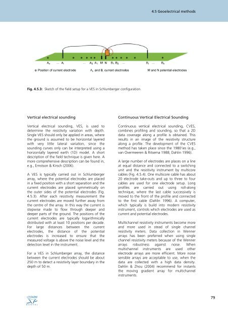
Fig. <strong>4.5</strong>.3: Sketch of the field setup for a VES in Schlumberger configuration.<br />
Vertical electrical sounding<br />
Vertical electrical sounding, VES, is used to<br />
determine the resistivity variation with depth.<br />
Single VES should only be applied in areas, where<br />
the ground is assumed to be horizontal layered<br />
with very little lateral variation, since the<br />
sounding curves only can be interpreted using a<br />
horizontally layered earth (1D) model. A short<br />
description of the field technique is given here. A<br />
more comprehensive description can be found in,<br />
e.g., Ernstson & Kirsch (2006).<br />
A VES is typically carried out in Schlumberger<br />
array, where the potential electrodes are placed<br />
in a fixed position with a short separation and the<br />
current electrodes are placed symmetrically on<br />
the outer sides of the potential electrodes (Fig.<br />
<strong>4.5</strong>.3). After each resistivity measurement the<br />
current electrodes are moved further away from<br />
the centre of the array. In this way the current is<br />
stepwise made to flow through deeper and<br />
deeper parts of the ground. The positions of the<br />
current electrodes are typically logarithmically<br />
distributed with at least 10 positions per decade.<br />
For large distances between the current<br />
electrodes, the distance of the potential<br />
electrodes is increased to ensure that the<br />
measured voltage is above the noise level and the<br />
detection level in the instrument.<br />
For a VES in Schlumberger array, the distance<br />
between the current electrodes should be about<br />
250 m to detect a resistivity layer boundary in the<br />
depth of 50 m.<br />
<strong>4.5</strong> <strong>Geoelectrical</strong> <strong>methods</strong><br />
Continuous Vertical Electrical Sounding<br />
Continuous vertical electrical sounding, CVES,<br />
combines profiling and sounding, so that a 2D<br />
data coverage along a profile is obtained. This<br />
results in an image of the resistivity structure<br />
along a profile. The development of the CVES<br />
method has taken place since the 1980’ies (e.g.,<br />
van Overmeeren & Ritsema 1988; Dahlin 1996).<br />
A large number of electrodes are places on a line<br />
at equal distance and connected to a switching<br />
unit and the resistivity instrument by multicore<br />
cables (Fig. <strong>4.5</strong>.4). One multicore cable has about<br />
20 electrode take-outs and up to three to four<br />
cables are used for one electrode setup. Long<br />
profiles are carried out using roll-along<br />
technique, where the last cable successively is<br />
moved to the front of the profile and connected<br />
to the first cable (Dahlin 1996). A computer,<br />
which typically is build into modern resistivity<br />
instrument, controls which electrodes are used as<br />
current and potential electrodes.<br />
Multichannel resistivity instruments become more<br />
and more used in stead of single channel<br />
resistivity meters. Data collection in Wenner<br />
arrays has been preferred when using single<br />
channel resistivity meters because of the Wenner<br />
arrays robustness against noise. When<br />
multichannel instruments are used other<br />
electrode arrays are more efficient. More noise<br />
sensible arrays are acceptable to use, when the<br />
data are collected with a high data density.<br />
Dahlin & Zhou (2004) recommend for instants<br />
the moving gradient array for multichannel<br />
instruments.<br />
79