4.5 Geoelectrical methods - LIAG
4.5 Geoelectrical methods - LIAG
4.5 Geoelectrical methods - LIAG

You also want an ePaper? Increase the reach of your titles
YUMPU automatically turns print PDFs into web optimized ePapers that Google loves.
<strong>4.5</strong>.4 Penetration depth<br />
The penetration depth depends on the chosen<br />
electrode array, maximum electrode spacing and<br />
the data density. Furthermore the resistivity<br />
structure in the ground and the contrast of the<br />
resistivity structures influence on the penetration<br />
depth. A conductive layer close to terrain tends<br />
to decrease the penetration depth since the<br />
current primarily would flow in the conductive<br />
layer. If a resistive layer overlies a conductive layer<br />
the penetration depth may increase as the<br />
current tends to flow in the deeper conductive<br />
layer.<br />
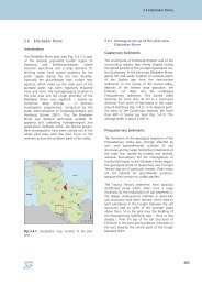
In an area with glacial deposits like in Denmark,<br />
northern Germany and parts of The Netherlands<br />
the geological variability is relatively large, thus it<br />
is very helpful to introduce the term “robust<br />
penetration depth”. When you talk about robust<br />
penetration depth the dimension in the data is<br />
taken into account. A CVES dataset is collected<br />
along a profile and interpreted using a 2D<br />
resistivity model, though the geological setting<br />
and the thereby resistivity structure varies in three<br />
dimensions. At large electrode spacings in a CVES<br />
profile the volume of the ground also<br />
perpendicular to the array and profile direction<br />
becomes so large that resistivity variations also<br />
perpendicular to the profile start to influence in<br />
the measurements. In Denmark the experience is<br />
that for a CVES profile the robust penetration<br />
depth is about 60 m. Likewise a VES maps the<br />
resistivity variation with depth at one point and is<br />
interpreted using a 1D resistivity model thus the<br />
resistivity structure may vary in three dimensions.<br />
For a VES it is even more critical if there are<br />
resistivity variations in the direction of the<br />
electrode array.<br />
<strong>4.5</strong>.5 Resolution<br />
It is difficult to give quantitative measures for the<br />
resolution. It depends on the number and the<br />
type of electrode arrays used, the resistivity<br />
structures and the resistivity contrast of the<br />
resistivity structures. Numerical studies for 1D<br />
models can be carried out in a systematic way<br />
(e.g., Christensen & Sørensen 2001). There are<br />
only a few examples on studies of the resolution<br />
of 2D models. Dahlin & Zhou (2004) show how<br />
different electrode arrays resolve five different 2D<br />
<strong>4.5</strong> <strong>Geoelectrical</strong> <strong>methods</strong><br />
models. From these results it is clearly seen that<br />
the resolution decreases both vertically and<br />
laterally by depth.<br />
By a rule of thump a horizontal resistivity<br />
structure should have a thickness of about 1.5–2<br />
times the layers above it to be well determined in<br />
a resistivity model. Thinner resistivity structures<br />
may be seen in the data and indication of the<br />
structure will appear in the resistivity model.<br />
Resistivity structures thinner than 1.5–2 times the<br />
layers above it may suffer from equivalences (see<br />
Sect. <strong>4.5</strong>.6.).<br />
<strong>4.5</strong>.6 Restrictions, uncertainties, error<br />
sources and pitfalls<br />
Restrictions in penetration depth with lowvoltage<br />
equipment<br />
The small low-voltage resistivity meters, which<br />
usually are used in groundwater surveys, would<br />
normally be applicable for mapping in the upper<br />
100 m. If deeper penetration is wanted, very<br />
large electrode spacings must be used, which<br />
require high voltage for generating enough<br />
current to arise a detectable potential difference.<br />
This means that heavier equipment including<br />
strong generators is needed for the fieldwork. In<br />
the planning of a geoelectrical survey with deep<br />
penetration depth, it is important to judge if the<br />
geological setting is suited for 1D or 2D data<br />
collection (see Sect. <strong>4.5</strong>.4 Penetration depth).<br />
Principle of equivalence<br />
The “principle of equivalence” is a serious<br />
problem for geoelectrical data. Equivalences<br />
occur, where a resistive layer lies in between two<br />
conductive layers or vice versa. If a relatively thin<br />
resistive layer lies in between two conductive<br />
layers, it may only be possible to determine the<br />
resistance of the layer, i.e., the product of the<br />
resistivity and the thickness. Therefore, a resistive<br />
layer and a layer with the half thickness and the<br />
double resistivity give very equal responses.<br />
Resistive layers should have a thickness more<br />
than 1.5–2 times the layers above it before the<br />
resistivity and the thickness of the layer can be<br />
resolved independently.<br />
85