4.5 Geoelectrical methods - LIAG
4.5 Geoelectrical methods - LIAG
4.5 Geoelectrical methods - LIAG

You also want an ePaper? Increase the reach of your titles
YUMPU automatically turns print PDFs into web optimized ePapers that Google loves.
80<br />
INGELISE MØLLER, KURT I. SØRENSEN & ESBEN AUKEN<br />
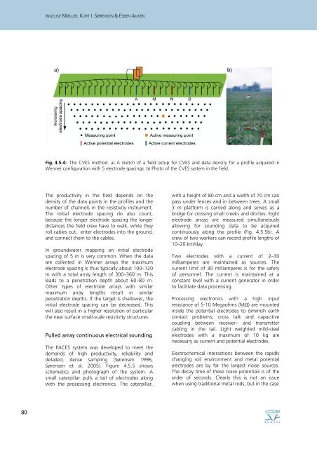
Fig. <strong>4.5</strong>.4: The CVES method. a) A sketch of a field setup for CVES and data density for a profile acquired in<br />
Wenner configuration with 5 electrode spacings. b) Photo of the CVES system in the field.<br />
The productivity in the field depends on the<br />
density of the data points in the profiles and the<br />
number of channels in the resistivity instrument.<br />
The initial electrode spacing do also count,<br />
because the longer electrode spacing the longer<br />
distances the field crew have to walk, while they<br />
roll cables out, enter electrodes into the ground,<br />
and connect them to the cables.<br />
In groundwater mapping an initial electrode<br />
spacing of 5 m is very common. When the data<br />
are collected in Wenner arrays the maximum<br />
electrode spacing is thus typically about 100–120<br />
m with a total array length of 300–360 m. This<br />
leads to a penetration depth about 60–80 m.<br />
Other types of electrode arrays with similar<br />
maximum array lengths result in similar<br />
penetration depths. If the target is shallower, the<br />
initial electrode spacing can be decreased. This<br />
will also result in a higher resolution of particular<br />
the near surface small-scale resistivity structures.<br />
Pulled array continuous electrical sounding<br />
The PACES system was developed to meet the<br />
demands of high productivity, reliability and<br />
detailed, dense sampling (Sørensen 1996,<br />
Sørensen et al. 2005). Figure <strong>4.5</strong>.5 shows<br />
schematics and photograph of the system. A<br />
small caterpillar pulls a tail of electrodes along<br />
with the processing electronics. The caterpillar,<br />
with a height of 80 cm and a width of 70 cm can<br />
pass under fences and in between trees. A small<br />
3 m platform is carried along and serves as a<br />
bridge for crossing small creeks and ditches. Eight<br />
electrode arrays are measured simultaneously<br />
allowing for sounding data to be acquired<br />
continuously along the profile (Fig. <strong>4.5</strong>.5b). A<br />
crew of two workers can record profile lengths of<br />
10–20 km/day.<br />
Two electrodes with a current of 2–30<br />
milliamperes are maintained as sources. The<br />
current limit of 30 milliamperes is for the safety<br />
of personnel. The current is maintained at a<br />
constant level with a current generator in order<br />
to facilitate data processing.<br />
Processing electronics with a high input<br />
resistance of 5-10 Megaohms (MΩ) are mounted<br />
inside the potential electrodes to diminish earth<br />
contact problems, cross talk and capacitive<br />
coupling between receiver– and transmitter<br />
cabling in the tail. Light weighted mild-steel<br />
electrodes with a maximum of 10 kg are<br />
necessary as current and potential electrodes.<br />
Electrochemical interactions between the rapidly<br />
changing soil environment and metal potential<br />
electrodes are by far the largest noise sources.<br />
The decay time of these noise potentials is of the<br />
order of seconds. Clearly this is not an issue<br />
when using traditional metal rods, but in the case