BajaPPC-750 User's Manual - Emerson Network Power
BajaPPC-750 User's Manual - Emerson Network Power
BajaPPC-750 User's Manual - Emerson Network Power
You also want an ePaper? Increase the reach of your titles
YUMPU automatically turns print PDFs into web optimized ePapers that Google loves.
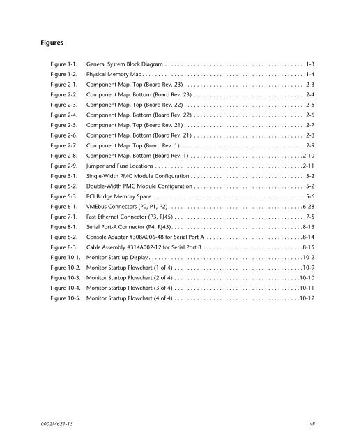
Figures<br />
Figure 1-1. General System Block Diagram . . . . . . . . . . . . . . . . . . . . . . . . . . . . . . . . . . . . . . . . . . . .1-3<br />
Figure 1-2. Physical Memory Map. . . . . . . . . . . . . . . . . . . . . . . . . . . . . . . . . . . . . . . . . . . . . . . . . . .1-4<br />
Figure 2-1. Component Map, Top (Board Rev. 23) . . . . . . . . . . . . . . . . . . . . . . . . . . . . . . . . . . . . . .2-3<br />
Figure 2-2. Component Map, Bottom (Board Rev. 23) . . . . . . . . . . . . . . . . . . . . . . . . . . . . . . . . . . .2-4<br />
Figure 2-3. Component Map, Top (Board Rev. 22) . . . . . . . . . . . . . . . . . . . . . . . . . . . . . . . . . . . . . .2-5<br />
Figure 2-4. Component Map, Bottom (Board Rev. 22) . . . . . . . . . . . . . . . . . . . . . . . . . . . . . . . . . . .2-6<br />
Figure 2-5. Component Map, Top (Board Rev. 21) . . . . . . . . . . . . . . . . . . . . . . . . . . . . . . . . . . . . . .2-7<br />
Figure 2-6. Component Map, Bottom (Board Rev. 21) . . . . . . . . . . . . . . . . . . . . . . . . . . . . . . . . . . .2-8<br />
Figure 2-7. Component Map, Top (Board Rev. 1) . . . . . . . . . . . . . . . . . . . . . . . . . . . . . . . . . . . . . . .2-9<br />
Figure 2-8. Component Map, Bottom (Board Rev. 1) . . . . . . . . . . . . . . . . . . . . . . . . . . . . . . . . . . .2-10<br />
Figure 2-9. Jumper and Fuse Locations . . . . . . . . . . . . . . . . . . . . . . . . . . . . . . . . . . . . . . . . . . . . . .2-11<br />
Figure 5-1. Single-Width PMC Module Configuration . . . . . . . . . . . . . . . . . . . . . . . . . . . . . . . . . . . .5-2<br />
Figure 5-2. Double-Width PMC Module Configuration . . . . . . . . . . . . . . . . . . . . . . . . . . . . . . . . . . .5-2<br />
Figure 5-3. PCI Bridge Memory Space. . . . . . . . . . . . . . . . . . . . . . . . . . . . . . . . . . . . . . . . . . . . . . . .5-6<br />
Figure 6-1. VMEbus Connectors (P0, P1, P2). . . . . . . . . . . . . . . . . . . . . . . . . . . . . . . . . . . . . . . . . .6-28<br />
Figure 7-1. Fast Ethernet Connector (P3, RJ45) . . . . . . . . . . . . . . . . . . . . . . . . . . . . . . . . . . . . . . . . .7-5<br />
Figure 8-1. Serial Port-A Connector (P4, RJ45). . . . . . . . . . . . . . . . . . . . . . . . . . . . . . . . . . . . . . . . .8-13<br />
Figure 8-2. Console Adapter #308A006-48 for Serial Port A . . . . . . . . . . . . . . . . . . . . . . . . . . . . . .8-14<br />
Figure 8-3. Cable Assembly #314A002-12 for Serial Port B . . . . . . . . . . . . . . . . . . . . . . . . . . . . . . .8-15<br />
Figure 10-1. Monitor Start-up Display . . . . . . . . . . . . . . . . . . . . . . . . . . . . . . . . . . . . . . . . . . . . . . . .10-2<br />
Figure 10-2. Monitor Startup Flowchart (1 of 4) . . . . . . . . . . . . . . . . . . . . . . . . . . . . . . . . . . . . . . . .10-9<br />
Figure 10-3. Monitor Startup Flowchart (2 of 4) . . . . . . . . . . . . . . . . . . . . . . . . . . . . . . . . . . . . . . .10-10<br />
Figure 10-4. Monitor Startup Flowchart (3 of 4) . . . . . . . . . . . . . . . . . . . . . . . . . . . . . . . . . . . . . . .10-11<br />
Figure 10-5. Monitor Startup Flowchart (4 of 4) . . . . . . . . . . . . . . . . . . . . . . . . . . . . . . . . . . . . . . .10-12<br />
0002M621-15 vii


