BajaPPC-750 User's Manual - Emerson Network Power
BajaPPC-750 User's Manual - Emerson Network Power
BajaPPC-750 User's Manual - Emerson Network Power

You also want an ePaper? Increase the reach of your titles
YUMPU automatically turns print PDFs into web optimized ePapers that Google loves.
3-10 <strong>BajaPPC</strong>-<strong>750</strong>: Central Processing Unit<br />
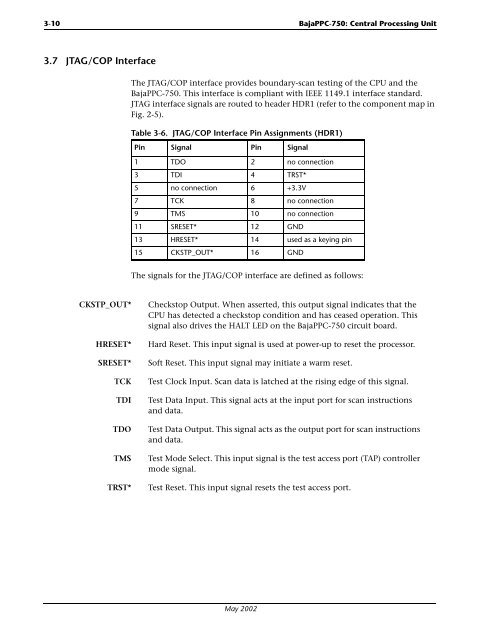
3.7 JTAG/COP Interface<br />
The JTAG/COP interface provides boundary-scan testing of the CPU and the<br />
<strong>BajaPPC</strong>-<strong>750</strong>. This interface is compliant with IEEE 1149.1 interface standard.<br />
JTAG interface signals are routed to header HDR1 (refer to the component map in<br />
Fig. 2-5).<br />
Table 3-6. JTAG/COP Interface Pin Assignments (HDR1)<br />
Pin Signal Pin Signal<br />
1 TDO 2 no connection<br />
3 TDI 4 TRST*<br />
5 no connection 6 +3.3V<br />
7 TCK 8 no connection<br />
9 TMS 10 no connection<br />
11 SRESET* 12 GND<br />
13 HRESET* 14 used as a keying pin<br />
15 CKSTP_OUT* 16 GND<br />
The signals for the JTAG/COP interface are defined as follows:<br />
CKSTP_OUT* Checkstop Output. When asserted, this output signal indicates that the<br />
CPU has detected a checkstop condition and has ceased operation. This<br />
signal also drives the HALT LED on the <strong>BajaPPC</strong>-<strong>750</strong> circuit board.<br />
HRESET* Hard Reset. This input signal is used at power-up to reset the processor.<br />
SRESET* Soft Reset. This input signal may initiate a warm reset.<br />
TCK Test Clock Input. Scan data is latched at the rising edge of this signal.<br />
TDI Test Data Input. This signal acts at the input port for scan instructions<br />
and data.<br />
TDO Test Data Output. This signal acts as the output port for scan instructions<br />
and data.<br />
TMS Test Mode Select. This input signal is the test access port (TAP) controller<br />
mode signal.<br />
TRST* Test Reset. This input signal resets the test access port.<br />
May 2002