BajaPPC-750 User's Manual - Emerson Network Power
BajaPPC-750 User's Manual - Emerson Network Power
BajaPPC-750 User's Manual - Emerson Network Power

You also want an ePaper? Increase the reach of your titles
YUMPU automatically turns print PDFs into web optimized ePapers that Google loves.
<strong>BajaPPC</strong>-<strong>750</strong> Circuit Board 2-13<br />
2.2.4 Reset/Interrupt Switch<br />
2.2.5 LED<br />
P4 P4 is an RJ45 connector for the front panel serial port A (standard<br />
configuration only). See Section 8.3.4 for pin assignments.<br />
J1x, J2x J1x (J11, J12, J14) and J2x (J21, J22, J24) are the two sets of PMC<br />
module connectors. Details and pin assignments are in Chapter 5.<br />
HDR1 HDR1 is a 16-pin JTAG\COP header that allows for boundaryscan<br />
testing of the <strong>Power</strong>PC CPU and the <strong>BajaPPC</strong>-<strong>750</strong>. See<br />
Section 3.7 for pin assignments.<br />
HDR2 HDR2 allows for PLD programming (factory use only).<br />
HDR3 HDR3 is a 14-pin header located on the front of the circuit board<br />
to accommodate EIA-232 communications from serial port B. See<br />
Section 8.3.4 for pin assignments.<br />
HDR4 HDR4 is a 16-pin debug header that allows additional access to<br />
various <strong>Power</strong>PC test signals. See Section 3.8 for pin assignments.<br />
This momentary two-position toggle switch can reset the <strong>BajaPPC</strong>-<strong>750</strong> or provide<br />
a level 6 interrupt to the CPU. It is located between serial port connector P4 and<br />
the LED on the front panel.<br />
The interrupt position on this switch may be used as a user-defined debugging<br />
tool. To determine the status of the interrupt switch, read bit zero of the 32-bit<br />
interrupt status register at FF9A,0070 16 ; a one indicates a switch interrupt. To clear<br />
the interrupt, write a one to the 8-bit register at FF9E,0000 16.<br />
The <strong>BajaPPC</strong>-<strong>750</strong> has a seven-segment LED on the front panel. The control register<br />
for this LED is located in a PLD at FF98,0000 16 . Each bit of this register controls<br />
a particular segment of the seven-segment display. To turn a segment on,<br />
write a one to its control bit. At power-up or after a system reset, all segments are<br />
off.<br />
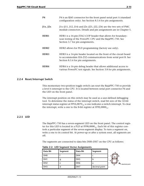
The segments are connected to data bits DH0–DH7 on the CPU as follows:<br />
Table 2-2. LED Segment Vector Assignments<br />
Data Bit Segment Data Bit Segment<br />
DH0 f DH4 c<br />
DH1 g DH5 b<br />
DH2 e DH6 a<br />
DH3 d DH7 decimal point<br />
0002M621-15<br />
e<br />
a<br />
f g<br />
d<br />
b<br />
c<br />
decimal point