

ADuM3190 (Rev. 0) - Analog Devices
ADuM3190 (Rev. 0) - Analog Devices
ADuM3190 (Rev. 0) - Analog Devices

You also want an ePaper? Increase the reach of your titles
YUMPU automatically turns print PDFs into web optimized ePapers that Google loves.
Data Sheet <strong>ADuM3190</strong><br />
DIN V VDE V 0884-10 (VDE V 0884-10) INSULATION CHARACTERISTICS<br />
These isolators are suitable for reinforced isolation only within the safety limit data. Maintenance of the safety data is ensured by<br />
protective circuits. The asterisk (*) marking branded on the package denotes DIN V VDE V 0884-10 approval for a 560 V peak working<br />
voltage.<br />
Table 6.<br />
Description<br />
Installation Classification per DIN VDE 0110<br />
Test Conditions/Comments Symbol Characteristic Unit<br />
For Rated Mains Voltage ≤ 150 V rms I to IV<br />
For Rated Mains Voltage ≤ 300 V rms I to III<br />
For Rated Mains Voltage ≤ 400 V rms I to II<br />
Climatic Classification 40/105/21<br />
Pollution Degree per DIN VDE 0110, Table 1 2<br />
Maximum Working Insulation Voltage VIORM 560 V peak<br />
Input-to-Output Test Voltage, Method B1<br />
Input-to-Output Test Voltage, Method A<br />
VIORM × 1.875 = Vpd(m), 100% production test,<br />
tini = tm = 1 sec, partial discharge < 5 pC<br />
Vpd(m) 1050 V peak<br />
After Environmental Tests Subgroup 1 VIORM × 1.5 = Vpd(m), tini = 60 sec,<br />
tm = 10 sec, partial discharge < 5 pC<br />
Vpd(m) 840 V peak<br />
After Input and/or Safety Test Subgroup 2 VIORM × 1.2 = Vpd(m), tini = 60 sec,<br />
Vpd(m) 672 V peak<br />
and Subgroup 3<br />
tm = 10 sec, partial discharge < 5 pC<br />
Highest Allowable Overvoltage VIOTM 3500 V peak<br />
Surge Isolation Voltage VPEAK = 10 kV; 1.2 µs rise time; 50 µs, 50% fall time VIOSM 4000 V peak<br />
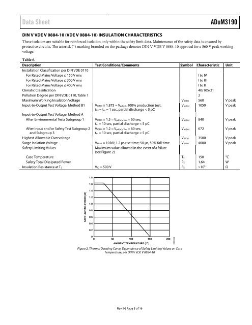
Safety Limiting Values Maximum value allowed in the event of a failure<br />
(see Figure 2)<br />
Case Temperature TS 150 °C<br />
Safety Total Dissipated Power PS 1.64 W<br />
Insulation Resistance at TS VIO = 500 V RS >109 Ω<br />
SAFE LIMITING POWER (W)<br />
1.8<br />
1.6<br />
1.4<br />
1.2<br />
1.0<br />
0.8<br />
0.6<br />
0.4<br />
0.2<br />
0<br />
0 50 100 150 200<br />
AMBIENT TEMPERATURE (°C) 11335-004<br />
Figure 2. Thermal Derating Curve, Dependence of Safety Limiting Values on Case<br />
Temperature, per DIN V VDE V 0884-10<br />
<strong>Rev</strong>. 0 | Page 5 of 16


