Millistak+HC AppGd_textC.qxd - Millipore
Millistak+HC AppGd_textC.qxd - Millipore
Millistak+HC AppGd_textC.qxd - Millipore
You also want an ePaper? Increase the reach of your titles
YUMPU automatically turns print PDFs into web optimized ePapers that Google loves.
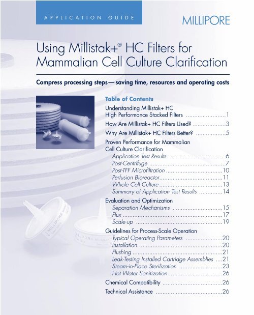
A P P L I C A T I O N G U I D E<br />
Â<br />
Using Millistak+ ®<br />
HC Filters for<br />
Mammalian Cell Culture Clarification<br />
Compress processing steps— saving time, resources and operating costs<br />
Table of Contents<br />
Understanding Millistak+ HC<br />
High Performance Stacked Filters ........................1<br />
How Are Millistak+ HC Filters Used? ....................3<br />
Why Are Millistak+ HC Filters Better? ..................5<br />
Proven Performance for Mammalian<br />
Cell Culture Clarification<br />
Application Test Results ..................................6<br />
Post-Centrifuge ..............................................7<br />
Post-TFF Microfiltration ..................................10<br />
Perfusion Bioreactor......................................11<br />
Whole Cell Culture ......................................13<br />
Summary of Application Test Results ..............14<br />
Evaluation and Optimization<br />
Separation Mechanisms ..............................15<br />
Flux ............................................................17<br />
Scale-up ....................................................19<br />
Guidelines for Process-Scale Operation<br />
Typical Operating Parameters ......................20<br />
Installation ..................................................20<br />
Flushing ......................................................21<br />
Leak-Testing Installed Cartridge Assemblies ....21<br />
Steam-in-Place Sterilization ..........................23<br />
Hot Water Sanitization ................................26<br />
Chemical Compatibility ....................................26<br />
Technical Assistance ........................................26<br />
1
Understanding<br />
Millistak+ HC High<br />
Performance Stacked Filters<br />
Millistak+ HC filters are a unique<br />
clarification/prefiltration tool<br />
developed to meet the critical needs<br />
of the biopharmaceutical industry.<br />
Designed expressly for large-scale<br />
mammalian cell fermentation<br />
processes, Millistak+ HC filters<br />
combine multiple clarification steps<br />
into a single unit operation.<br />
Innovative Dual-Action Filter<br />
The technology is built upon the<br />
superior performance qualities of<br />
the cellulosic filter media available<br />
in the Millistak+ filter product line.<br />
The DE Series filter media consists of<br />
refined cellulose fibers and high-purity<br />
diatomaceous earth. The composite<br />
is chemically treated to impart a<br />
cationic (positive) surface charge,<br />
to enable the capture of negativelycharged<br />
biological particulates and<br />
colloids (cell fragments, protein<br />
agglomerates, etc.).<br />
Millistak+ HC filters represent the<br />
next generation of the stacked-disk,<br />
cellulosic depth filter. The principal<br />
design feature of Millistak+ HC filters<br />
is a graded pore structure, tailored to<br />
maximize the holding capacity of the<br />
filter for the broad range of particle<br />
sizes typical of fermentation fluids.<br />
Two full-thickness cellulosic pads<br />
are employed—a fine grade media<br />
overlaid by a coarser grade—which<br />
together span a far wider range of<br />
pore size than achievable in any<br />
single-grade filter. For particular<br />
configurations of Millistak+ HC filters,<br />
the construction is further enhanced by<br />
the addition of a microporous cellulose<br />
membrane underlying the dual-layer<br />
depth filter media, to further extend<br />
small particle retention.<br />
Millistak+ HC Filter<br />
Open DE Grade<br />
Tighter DE Grade<br />
Cellulosic Membrane<br />
For process-scale operations,<br />
Millistak+ HC filters are available<br />
as a lenticular, stacked-disk cartridge<br />
containing eight double-sided, 16-inch<br />
diameter disks for 1.8 m 2 frontal<br />
Millistak+ HC Filters Application Guide 1<br />
Flow<br />
Figure 1. Media Layers of Millistak+ HC<br />
Filters
Figure 2. Millistak+ HC Stacked-Cell<br />
Cartridges Used in a Large-Scale Process<br />
2<br />
TFF<br />
NFF<br />
Centrifuge<br />
surface area. Up to eight stacked-disk<br />
cartridges can be assembled in a<br />
single housing. For smaller-scale<br />
testing, Millistak+ HC filters are also<br />
available in disposable 650 cm 2<br />
and 23 cm 2 cartridges.<br />
For complete details on the product<br />
line, refer to the Millistak+ HC Filters<br />
Data Sheet (Lit. No. DS1000EN00).<br />
Primary Secondary Sterile<br />
10 – 40 NTU<br />
50 – 200 NTU<br />
200 – 600 NTU<br />
Figure 3. Typical Downstream Recovery Process<br />
0.5–5 NTU<br />
NFF NFF<br />
0.1– 1 NTU<br />
NTU = Normal Turbidity Unit<br />
www.millipore.com
How Are Millistak+ HC<br />
Filters Used?<br />
The typical downstream recovery<br />
process for mammalian cell derived<br />
biologics consists of multiple clarification<br />
steps to prepare the liquid-borne<br />
product for either sterile filtration or<br />
direct chromatographic purification.<br />
In the first stage or primary separation<br />
step, the bulk of the cell mass is<br />
removed from the broth—depending<br />
on the volume and type of fermentation<br />
process, different clarification<br />
methods are used, as shown in<br />
Figure 3.<br />
Batch Processing<br />
In large-scale (> 1,000 liter) batch<br />
and fed-batch fermentations, the bulk<br />
of the cell mass is ordinarily separated<br />
by centrifugation or tangential flow<br />
microfiltration. For small batch fermentations<br />
(< 1,000 liter), cartridge depth<br />
filters (NFF) are often used in the pore<br />
size range of 3–5 µm.<br />
Perfused Bioreactor<br />
In contrast to batch processes, perfused<br />
bioreactors are harvested continuously<br />
over extended operating periods<br />
lasting several weeks or months.<br />
For primary clarification, the flowcontrolled<br />
product stream from the<br />
perfusion bioreactor will typically pass<br />
through either a membrane separator<br />
(hollow fiber TFF) or a gravity settler,<br />
with the cell mass recycled to the<br />
fermenter. The crude product is pooled<br />
and then batch-processed for secondary<br />
clarification and final sterile filtration.<br />
A Single Step for Clarification<br />
and Prefiltration<br />
The effluent of these various primary<br />
clarification steps is generally unsuitable<br />
for either sterile filtration or<br />
chromatographic processing. The level<br />
of suspended matter in all cases<br />
(which varies by method) will cause<br />
rapid downstream fouling, with significant<br />
cost impact. The turbidity ranges<br />
noted in the process schematic in<br />
Figure 3 are indicative of the particle<br />
loads present. Even in the case of<br />
TFF microfiltration—typically executed<br />
with a 0.45 – 0.65 µm membrane—<br />
particle loading in the permeate does<br />
not allow for direct sterile filtration at<br />
any reasonable capacity or cost.<br />
Further clarification is required, for<br />
which disposable NFF filters are<br />
normally used (depth or surface types).<br />
The challenge confronting the process<br />
engineer is to arrive at an integrated<br />
clarification and sterile filtration train that<br />
will minimize overall production costs.<br />
In many cases, secondary clarification<br />
of tissue culture fluid involves several<br />
(two or three) serial filtration steps. The<br />
need for multiple separations arises from<br />
the broad range of particle sizes and<br />
Millistak+ HC Filters Application Guide 3
types present in the process stream.<br />
Millistak+ HC filters consolidate these<br />
multiple serial filtration steps into a<br />
single operation.<br />
Media Configurations Specific<br />
to Your Application<br />
Extensive field testing on a variety of<br />
bioprocess streams has led to the<br />
development of three Millistak+ HC<br />
filter configurations, each containing<br />
dual-layer cellulosic depth filter media<br />
in grade combinations best suited<br />
to a particular clarification role<br />
(see table below).<br />
4<br />
More than Cell Culture Clarification<br />
Millistak+ HC filters are an excellent<br />
clarification tool for a number of<br />
associated biopharmaceutical<br />
process applications:<br />
• cell culture growth media<br />
(MEM, peptones)<br />
• plasma fraction products<br />
• vaccines<br />
As in biologics manufacturing,<br />
Millistak+ HC filters offer an economical<br />
and effective means of protecting<br />
downstream sterilizing grade filters,<br />
to achieve optimum overall process<br />
efficiencies.<br />
Media Characteristics Media Construction<br />
A1HC*<br />
For post-TFF Tightest media 60DE + 75DE + RW01<br />
clarification fluids combination<br />
B1HC*<br />
For post-centrifuge A more open 50DE + 75DE + RW01<br />
or settled permeate first layer<br />
containing cellular<br />
particulate<br />
C0HC<br />
For perfusion Two layers of 30DE + 60DE<br />
bioreactor fluid an open Millistak+<br />
DE media<br />
*A1HC and B1HC include the same secondary layer and a membrane layer<br />
proven to protect downstream 0.22 µm membranes.<br />
www.millipore.com
Why Are Millistak+ HC<br />
Filters Better?<br />
Biological solids exhibit poor filter<br />
cake properties—very thin deposits<br />
exhibit very high flow resistance.<br />
The capacity of a clarifying depth<br />
filter is, therefore, highly dependent<br />
on the accessible internal surface<br />
area available for particle deposition.<br />
For a given media type and grade,<br />
capacity increases linearly with<br />
thickness or bed depth. Moreover,<br />
as commonly occurs in biological<br />
suspensions, the particles span a<br />
broad range of sizes—to maximize<br />
capacity, the filter media must be<br />
structured to accommodate these<br />
particle sizes in proportion to their<br />
number. For this reason, a gradient<br />
pore structure or media density<br />
is optimal.<br />
Outperforms the Competition<br />
Based on these design criteria,<br />
Millistak+ HC filters have been<br />
developed to outperform all competitive<br />
depth filters. Each cellulosic<br />
pad within the multilayer composite<br />
possesses a graded pore structure<br />
from front to back. Coupling two<br />
such pads in series expands the<br />
effective pore size range by as<br />
much as several orders of magnitude.<br />
In addition, Millistak+ HC filters<br />
employ two full-thickness cellulosic<br />
pads for an overall bed depth of more<br />
than 0.260 in.—thicker than any<br />
other cellulosic depth filter on the<br />
market today.<br />
Unique Membrane Layer<br />
Improves Performance<br />
A major advance in the design of<br />
stacked-disk prefilters, as offered in<br />
Millistak+ HC filters, is the incorporation<br />
of a microporous membrane layer,<br />
downstream of the cellulosic pads.<br />
The membrane layer delivers two<br />
important advantages. First, it serves<br />
as a final barrier to trap small particles<br />
and colloids that would otherwise<br />
foul a trailing sterile filter. Secondly,<br />
the membrane contributes a modest<br />
hydraulic resistance to the filter,<br />
which significantly improves feed<br />
flow distribution and, consequently,<br />
media utilization. All vertical stackeddisk<br />
designs inherently force a greater<br />
percentage of feed flow to the lower<br />
sections of the filter column, which<br />
are under higher hydrostatic pressure.<br />
The addition of the microporous<br />
membrane to Millistak+ HC filters<br />
helps to minimize this vertical pressure<br />
gradient, to utilize all available filter<br />
area more evenly and efficiently.<br />
Millistak+ HC Filters Application Guide 5
Proven Performance<br />
for Mammalian<br />
Cell Culture Clarification<br />
The benefits of the unique Millistak+<br />
HC filter construction are exemplified<br />
in Figure 4. The test fluid is a typical<br />
mammalian cell culture, which had<br />
been centrifuged for bulk biomass<br />
removal: the centrifugation had<br />
reduced the turbidity of the suspension<br />
to 96 NTU, at which level the prefilter<br />
exhibits little pressure build-up and<br />
overall performance is judged by the<br />
downstream sterile filter capacity.<br />
6<br />
0.22 µm Durapore Resistance<br />
(psid/LMH)<br />
0.040<br />
0.035<br />
0.030<br />
0.025<br />
0.020<br />
0.015<br />
0.010<br />
0.005<br />
0.000<br />
CHO Centrate: 96 NTU<br />
0<br />
Figure 4. Effect of Bed Height and Membrane Layer<br />
Application Test Results<br />
The individual contributions of the<br />
three media types that comprise<br />
A1HC were evaluated. As shown in<br />
Figure 4, the 75DE layer was tested<br />
alone, then the combined 60DE/<br />
75DE pairing and finally the A1HC<br />
combination (which includes the microporous<br />
membrane). The benefit of the<br />
increased thickness and expanded<br />
pore-size range of the two pad layers<br />
is evident in the substantial increase in<br />
sterile filter capacity—which was<br />
more than doubled—around the<br />
0.010 psid/LMH level (representing<br />
75DE<br />
60DE + 75DE<br />
A1HC: 60DE + 75DE + RW01<br />
200 400 600 800 1000 1200 1400<br />
0.22 µm Durapore ® Membrane Throughput (L/m 2 )<br />
www.millipore.com
typical operating conditions). The<br />
addition of the membrane layer further<br />
enhances the retention capability of<br />
the A1HC prefilter, to increase sterile<br />
filter protection dramatically.<br />
In order to achieve this level of<br />
sterile filter capacity, the prefilter must<br />
be highly retentive to small particles<br />
and colloidal materials. The correlation<br />
of sterile filter capacity with the turbidity<br />
of prefilter effluent is shown in<br />
Figure 5. The data show that, to reach<br />
sterile filter capacities in the range of<br />
500 L/m 2 , the prefilter must reduce<br />
fluid turbidity to well below 10 NTU.<br />
0.22 µm Durapore Capacity<br />
(L/m2 @ 20 psid)<br />
700<br />
600<br />
500<br />
400<br />
300<br />
200<br />
100<br />
0<br />
0<br />
Clarified Mammalian Cell Culture<br />
Figure 5. Sterile Filter Capacity as a Function of Feed Turbidity<br />
Depending on the primary clarification<br />
process employed (as shown<br />
in the process schematic in Figure 3<br />
above), secondary clarification will<br />
further reduce turbidity levels by a<br />
factor of 5:1—100:1. Note that<br />
monitoring effluent turbidity can be<br />
a useful guide in determining prefilter<br />
performance, but it should not be used<br />
for actual sterile filter sizing, due to<br />
the complexities of membrane fouling.<br />
Post-Centrifuge<br />
Centrifugation is by far the most<br />
widely practiced method of bulk<br />
cell mass removal for fermentation<br />
10 20 30 40 50<br />
Turbidity (NTU)<br />
1.54 PCV,<br />
60% Viability<br />
Millistak+ HC Filters Application Guide 7
oths. For this particular case study,<br />
the centrifugation process reduced the<br />
suspended matter to a level corresponding<br />
to a turbidity of 110 –175 NTU.<br />
Side-by-side tests were run on<br />
each of the three Millistak+ HC filter<br />
device sizes to clarify the cell culture<br />
centrate. Each prefilter device (B1HC<br />
media) was operated in tandem with<br />
a trailing sterile filter under constant<br />
flux conditions, all units drawing on the<br />
same lot of feed material. As shown in<br />
Figure 6, the performance profiles for<br />
the three device sizes—plotted<br />
as total system pressure differential<br />
Figure 6. Prefilter and Sterile Filter Scale-up<br />
8<br />
Total System Pressure<br />
Differential (psid)<br />
35<br />
30<br />
25<br />
20<br />
15<br />
10<br />
5<br />
0<br />
0<br />
Cell Culture: Centrate<br />
Lab-Scale (3 Trials)<br />
Pilot-Scale<br />
Process-Scale<br />
(prefilter + sterile filter) relative to<br />
prefilter throughput or capacity—<br />
were reasonably consistent with<br />
one another. The same figure also<br />
shows that there was some variability<br />
among the three trials that were run<br />
with the smallest, lab-scale device.<br />
This illustrates the need to run multiple<br />
lab-scale tests, in order to normalize<br />
for variability in process stream and<br />
filter media, before scaling up to<br />
pilot-scale and process-scale tests.<br />
This is discussed in more detail later,<br />
under Scale-up, in the section on<br />
Evaluation and Optimization.<br />
50 100 150 200 250 300 350 400<br />
Prefilter Capacity (L/m2)<br />
1.54 PCV,<br />
60% Viability<br />
Feed Turbidity:<br />
80 –100 NTU<br />
Prefilter Flux:<br />
100 –170 LMH<br />
Prefilter: B1HC<br />
www.millipore.com
The moderately higher capacities<br />
achieved with the pilot-scale Opticap <br />
prefilter and process-scale (16-inch)<br />
Although the prefilter accounts for the<br />
majority of the pressure build-up in the<br />
system, the comparatively small sterile<br />
filter area used in the lab-scale tests<br />
exaggerates its pressure contribution.<br />
As a result, the lab tests underestimate<br />
the capacities achieved with the relatively<br />
larger sterile filters used in the<br />
pilot- and process-scale tests.<br />
stacked-disk filter are due to differences<br />
in the relative areas of the sterile filters<br />
used, as shown in the following table:<br />
Prefilter Area Sterile Filter Area Area Ratio<br />
Lab-scale 23 cm 2 4 cm 2 5.7<br />
Pilot-scale 650 cm 2 200 cm 2 3.3<br />
Process-scale 1.8 m 2 0.69 m 2 2.5<br />
These and other tests have produced<br />
the following results in process-scale<br />
trials for secondary clarification of a<br />
CHO cell culture prior to sterile filtration<br />
(0.22 µm). The ratio of prefilter<br />
area to sterile filter area is approximately<br />
2.5 :1. Performance is measured<br />
at a constant feed rate (flux) to<br />
the prefilter of 100–150 LMH:<br />
Capacity Pressure<br />
(L/m 2 ) Differential (psid)<br />
Run 1: 60% Cell Viability<br />
Millistak+ HC B1HC Prefilter 476 30<br />
0.22 µm Durapore Filter 1100 5<br />
Run 2: 80% Cell Viability<br />
Millistak+ HC B1HC Prefilter 443 30<br />
0.22 µm Durapore Filter 1088 5.5<br />
Millistak+ HC Filters Application Guide 9
Post-TFF Microfiltration<br />
Mammalian cell cultures clarified by<br />
means of crossflow (TFF) microfiltration<br />
will typically utilize a membrane in<br />
the 0.45–0.65 µm range. Even at<br />
this high degree of separation, the<br />
treated effluent (permeate) frequently<br />
requires further clarification in order<br />
to achieve acceptable capacities in<br />
subsequent sterile filtration. The preferred<br />
Millistak+ HC prefilter for these<br />
low solids fluids is the A1HC. When<br />
applied to a post-TFF process stream,<br />
this prefilter will ordinarily develop little<br />
pressure build-up, yet will provide a<br />
remarkable improvement in downstream<br />
sterile filter throughput.<br />
Sterile Filter (0.22 µm)<br />
Capacity (L/m2 )<br />
10<br />
700<br />
600<br />
500<br />
400<br />
300<br />
200<br />
100<br />
0<br />
CHO Cell Culture: TFF/MF Permeate<br />
Competitor A<br />
Single Layer<br />
Media<br />
Competitor A<br />
Dual Layer<br />
Media<br />
Figure 7. Competitive Prefilter Analysis: Sterile Filter Protection<br />
In one example, a fed-batch CHO<br />
cell culture was first processed using a<br />
0.65 µm TFF/MF (Prostak ) filter system<br />
with Durapore membrane and the<br />
permeate was batch-filtered through<br />
the A1HC, followed by a 0.22 µm<br />
Durapore sterilizing filter (prefilter flux =<br />
150–160 LMH). The A1HC was able<br />
to achieve a process capacity of over<br />
500 L/m 2 , while never exceeding<br />
a pressure differential of 5 psid. The<br />
throughput on the trailing sterile filter<br />
was greater than 3000 L/m 2 .<br />
Figure 7 illustrates the performance<br />
benefit of Millistak+ HC filters over<br />
competitive products, in side-by-side<br />
trials on a mammalian cell culture<br />
Competitor B<br />
Single Layer<br />
Media<br />
Millistak+<br />
A1HC<br />
Prefilter Flux:<br />
37 LMH<br />
Sterile Filter Flux:<br />
200 LMH<br />
www.millipore.com
after microfiltration (0.65 µm). The<br />
competitive products represent similar<br />
stacked-disk prefilters, based on both<br />
single- and double-layer cellulosic<br />
media. In all tests, the prefilter exhibited<br />
little or no pressure build-up—<br />
performance was measured according<br />
to the volume of filtrate that could be<br />
processed subsequently through a<br />
sterilizing-grade (0.22 µm) filter.<br />
As shown, the A1HC outperformed<br />
all other products tested, demonstrating<br />
that the proper design of depth filter<br />
media and bi-layer configuration will<br />
result in superior sterile filter protection.<br />
Perfusion<br />
Bioreactor<br />
Biomass<br />
300 – 400 NTU<br />
Depth<br />
Filter<br />
Figure 8. Processing of Perfusion Bioreactor Product<br />
Perfusion Bioreactor<br />
A side-by-side test of Millistak+ HC<br />
filters and several competitive single<br />
and multilayer stacked-disk products<br />
was conducted on a mammalian cell<br />
(CHO) perfusion process. As shown in<br />
Figure 8, the perfusion process generates<br />
two types of material, which are<br />
accumulated and batch-processed.<br />
The majority of the process fluid<br />
(~70%) is a crude product, harvested<br />
from the bioreactor through a screening<br />
mechanism, which must be further<br />
clarified before final filtration through<br />
a 0.45 µm membrane. In addition,<br />
the bioreactor is periodically purged<br />
Spin<br />
Filter<br />
Cell Harvest<br />
40 NTU<br />
0.45 µm<br />
Sterile Filter<br />
Millistak+ HC Filters Application Guide 11
to control cell density and contaminant<br />
levels. This raw cell culture is, similarly,<br />
clarified and sterile filtered to recover<br />
contained product. The suspended<br />
solids content of the raw cell culture is<br />
many times that of the prefiltered harvest<br />
fluid, as indicated by their relative<br />
turbidities (300 NTU versus 40 NTU).<br />
All tests were run at constant<br />
flow (150–200 L/m 2 /hr, based<br />
on prefilter area), with the clarifying<br />
prefilter and sterile filter operated<br />
in tandem.<br />
During the early growth phase of<br />
the culture with cell counts low, the<br />
12<br />
Sterile Filter Pressure<br />
Differential (psid)<br />
16<br />
14<br />
12<br />
10<br />
8<br />
6<br />
4<br />
2<br />
prefilters displayed little or no pressure<br />
build-up: the capacity of the filter train<br />
was dictated by the pressure build-up<br />
on the downstream 0.45 µm filter.<br />
Figure 9 shows the pressure-volume<br />
profiles for the Millistak+ C0HC filter<br />
and two trial runs of the competitive<br />
product, using process-scale multilayer<br />
stacked-disk filter cartridges. The<br />
C0HC prefilters clearly demonstrated<br />
a capacity to retain not only the<br />
preclarified cell culture (harvest fluid)<br />
but also a relatively large portion of<br />
the untreated culture, in far greater<br />
volumes than the competitive product.<br />
Mammalian Cell Culture Perfusate Clarification<br />
C0HC: Preclarified Harvest<br />
C0HC: Unclarified Harvest<br />
Competitor: Harvest, Run 1<br />
Competitor: Harvest, Run 2<br />
0<br />
0 50 100 150 200 250 300 350 400<br />
Process Volume (L)<br />
Figure 9. Competitive Prefilter Analysis for Perfusion Bioreactor Product (Early)<br />
www.millipore.com
Tests run later in the perfusion cycle<br />
(when cell densities and contaminant<br />
levels are higher), showed significant<br />
pressure build-up on both prefilters and<br />
sterile filters for competitive products<br />
(see Figure 10). The Millistak+ C0HC<br />
filter repeatedly demonstrated far<br />
greater capacities for both preclarified<br />
and untreated biomass over<br />
competitive prefilter products.<br />
Whole Cell Culture<br />
A series of lab-scale tests were<br />
conducted on a CHO cell culture<br />
processed directly from a batch<br />
Capacity (L/m 2 )<br />
500<br />
400<br />
300<br />
200<br />
100<br />
0<br />
20 psid<br />
Competitor A<br />
Multilayer<br />
Biomass<br />
Cell Harvest<br />
20 psid<br />
Competitor A<br />
High Capacity<br />
Single Layer<br />
20 psid<br />
Competitor A<br />
Multilayer<br />
fermenter: the broth contained a cell<br />
density of 6 x 10 6 /mL, corresponding<br />
to 1.5% packed cell volume<br />
(cell viability 90%). The C0HC<br />
prefilter was applied in tandem with<br />
a 0.22 µm sterile filter (area ratio 6:1)<br />
at a constant prefilter flux of 160 LMH.<br />
The C0HC reached a capacity of<br />
215 L/m 2 , on average, at a pressure<br />
differential of 20 psid: the sterile filter<br />
(which showed no significant pressure<br />
build-up) reached a corresponding<br />
capacity of 1100 L/m 2 .<br />
20 psid<br />
B1HC C0HC C0HC C0HC<br />
Filter Type<br />
4.5 psid 4.5 psid<br />
Figure 10. Competitive Prefilter Analysis for Perfusion Bioreactor Product (Late)<br />
6.5 psid<br />
Millistak+ HC Filters Application Guide 13
Summary of Application Test Results<br />
The following table presents a summary<br />
of the various applications tested with<br />
Millistak+ HC filters. Values are given<br />
0.2 µm<br />
Millistak+ HC Millistak+ HC Sterile Filter<br />
Media Capacity Capacity<br />
Application Grades (L/m 2 ) (L/m 2 )<br />
Human Serum A1HC 120 —<br />
E. coli Lysate: Centrate B1HC 35 —<br />
E. coli (20% Viability) C0HC 20 120<br />
Mammalian Cell Culture (10% FBS) C0HC 60 130<br />
Mammalian Cell Culture C0HC 125 > 200<br />
Mammalian Cell Culture:<br />
post-MF (0.65 µm) B1HC 400 1500<br />
Bacterial Fermentation: Centrate B1HC 130 —<br />
14<br />
for the approximate prefilter and<br />
trailing sterile filter capacities<br />
achieved in these tests.<br />
www.millipore.com
Evaluation and<br />
Optimization<br />
Separation Mechanisms<br />
The particle removal achieved by<br />
Millistak+ HC filters is the consequence<br />
of two distinct separation mechanisms.<br />
The first of these mechanisms is<br />
mechanical sieving, in which particles<br />
are captured within the prefilter due to<br />
their physical size and/or orientation.<br />
In the case of a depth filter, the path<br />
through the media matrix is tortuous<br />
and varies greatly in effective pore<br />
dimensions, providing ample opportunity<br />
for particle retention by entrapment.<br />
The outward effect, typical of<br />
most filters, is a build-up in pressure<br />
differential in the direction of flow.<br />
The second particle capture<br />
mechanism for Millistak+ HC filters<br />
is adsorption: the physical/chemical<br />
binding of particles to the filter media.<br />
This process is aided by the net<br />
positive charge on the surface of the<br />
Millistak+ HC filter media. Colloidal<br />
particles in a biological suspension<br />
(cell wall fragments, agglomerated<br />
proteins, polynucleic acids, etc.)<br />
exhibit a net negative electrostatic<br />
charge on their surface at typical<br />
near-neutral pH conditions. The<br />
cationic charge on the Millistak+ HC<br />
filter media allows these particles to<br />
be captured, when otherwise they<br />
might escape retention due to their<br />
small size.<br />
This electrostatic retention mechanism<br />
allows the Millistak+ HC prefilter<br />
to be effective in removing particles<br />
well below the smallest pore size<br />
of the media and thereby provides<br />
additional protection to the sterile filter.<br />
This capture mechanism does not<br />
however reveal itself as a pressure<br />
build-up on the prefilter. Instead, the<br />
user must carefully monitor the quality<br />
of the filtrate, to detect the point at<br />
which all available adsorption sites<br />
within the media have been used.<br />
This can be done either by monitoring<br />
filtrate turbidity in relation to process<br />
throughput or by measuring the<br />
capacity of the downstream sterile<br />
filter in situ or off-line (with a post-run<br />
Vmax SM test).<br />
Depending on the properties of<br />
the feed stream (and the consequent<br />
relative contribution of the two separation<br />
mechanisms described above),<br />
two distinct types of behavior may<br />
be observed for the Millistak+ HC<br />
prefilter. These two distinct profiles<br />
Millistak+ HC Filters Application Guide 15
Figure 11. Two Types of Behavior Observed for the Millistak+ HC Prefilter<br />
16<br />
Breakthrough Limited<br />
Pressure Differential (psid)<br />
Pressure Limited<br />
Pressure Differential (psid)<br />
25<br />
20<br />
15<br />
10<br />
5<br />
25<br />
20<br />
15<br />
10<br />
5<br />
Turbidity<br />
Pressure Differential<br />
0<br />
0<br />
0 5 10 15 20 25<br />
Volume Filtered per Unit Area<br />
(L/m 2 )<br />
Turbidity<br />
Pressure Differential<br />
10<br />
0<br />
0<br />
0 5 10 15 20 25<br />
Volume Filtered per Unit Area<br />
(L/m 2 )<br />
10<br />
8<br />
6<br />
4<br />
2<br />
8<br />
6<br />
4<br />
2<br />
Turbidity (NTU)<br />
Turbidity (NTU)<br />
www.millipore.com
are shown in Figure 11. When the<br />
dominant capture mechanism is<br />
adsorption, filtrate turbidity will be<br />
seen to rise markedly, as the capacity<br />
of the prefilter is reached, while the<br />
pressure differential across it rises more<br />
slowly; this profile is known as “breakthrough<br />
limited.” When the dominant<br />
capture mechanism is mechanical<br />
sieving, the pressure differential<br />
across the prefilter will be seen<br />
to rise markedly, as its capacity is<br />
reached, while filtrate turbidity rises<br />
Feed<br />
Pump<br />
Figure 12. Test Configuration for<br />
Millistak+ HC Filter<br />
Prefilter<br />
Millistak+ HC Filters Application Guide<br />
P<br />
P<br />
Sterile<br />
Filter<br />
more slowly; this profile is known as<br />
“pressure limited.” Testing is required to<br />
determine which of these applies and,<br />
therefore, whether a prefilter “pressure<br />
limit” or a “breakthrough limit” should<br />
be employed in overall filter train sizing.<br />
It is strongly recommended that,<br />
during testing of a Millistak+ HC filter,<br />
it should be coupled with a sterilizing<br />
grade filter in series (e.g., 0.22 µm<br />
hydrophilic Durapore cartridge), as<br />
shown in Figure 12. While simulating<br />
the typical filtration process, this test<br />
configuration can tell the user whether<br />
the prefilter is performing correctly, or<br />
if a change needs to be made either<br />
to the prefilter type or to the ratio of<br />
prefilter area to sterile filter area.<br />
If creating a serial filtration test,<br />
as illustrated above, is not feasible,<br />
samples of filtrate from a Millistak+ HC<br />
filter can be collected and tested<br />
off-line, as prescribed by <strong>Millipore</strong>’s<br />
Vmax sizing method.<br />
Flux<br />
Flux is an important process parameter,<br />
especially for depth filtration. Flux is<br />
flow rate normalized for filtration area<br />
and is usually expressed in LMH<br />
(liters per hour, per square meter).<br />
Flux is significant also with regard<br />
to the adsorptive contribution of<br />
the Millistak+ HC filter media. The<br />
faster a particle is flowing through a<br />
17
Figure 13. Effect of Flux on Capacity of Millistak+ HC Filters<br />
Millistak+ HC filter, the less likely it is<br />
to interact electrostatically with the<br />
charged surfaces, and consequently,<br />
the more likely it is to pass directly<br />
through the filter. If, however, the flow<br />
rate (or velocity) is slowed, and the<br />
particle is given additional time to<br />
migrate to the surface of the media,<br />
the chances of it being removed from<br />
the solution are increased. This effect<br />
18<br />
Pressure Differential<br />
(psid)<br />
30 75DE Media<br />
25<br />
Flux (LMH) = 734 491 258 108<br />
0.375 g/L Dairy<br />
Whey Solution<br />
20<br />
Solution Turbidity:<br />
44 NTU<br />
15<br />
10<br />
Duplicate Tests,<br />
Each Flux Level<br />
5<br />
0<br />
0 50<br />
100 150 200 250<br />
Capacity (L/m 2 )<br />
is depicted in Figure 13, which shows<br />
that the capacity of the Millistak+ HC<br />
prefilter is proportionately increased,<br />
as the flux is reduced. Process designers<br />
should search for the optimum flux at<br />
which a given process should be run,<br />
to minimize process time and maximize<br />
filter efficiency. The initial recommended<br />
flux range for Millistak+ HC filters is<br />
150–400 LMH.<br />
www.millipore.com
Scale-up<br />
During the optimization process, tests<br />
should be run at three separate scales,<br />
and Millistak+ HC filters are available<br />
in device sizes to match these steps.<br />
Initial experiments can be run on<br />
the two smaller Millistak+ HC filters.<br />
Care should be taken to operate<br />
in a constant-flux manner, recording<br />
the pressure increase. If desired,<br />
<strong>Millipore</strong>’s Pmax SM system can be<br />
employed, to increase the efficiency<br />
of interpreting the test data.<br />
First, to determine the correct type<br />
of Millistak+ HC filters to incorporate<br />
into the process, screening with test<br />
volumes of 100–1000 mL can be<br />
performed with the Millistak+ HC Mini<br />
Capsule (23 cm 2 ). To normalize for<br />
variability in filter media and process<br />
stream, multiple tests (at least three)<br />
are recommended, with different<br />
batches of test fluid.<br />
The next step would be to process<br />
5–25 L of solution through an Opticap<br />
capsule filter with Millistak+ HC media<br />
(650 cm 2 ). Again, testing multiple<br />
devices with multiple process samples<br />
will ensure that the sizing is as accurate<br />
as possible.<br />
When the process has been well<br />
characterized, the process-scale<br />
device can be tested, on volumes<br />
greater than 50 L. Each processscale<br />
16-inch 8-cell cartridge<br />
provides 1.8 m 2 of filtration area.<br />
Care should be taken to<br />
simulate as closely as possible the<br />
final process conditions. Since biological<br />
process streams are very complex<br />
mixtures, their properties could change<br />
drastically if any process parameters<br />
have been changed. If the temperature<br />
of the fluid is not kept constant,<br />
if the age of the fermentation is<br />
changed or if it is stored overnight<br />
under refrigeration, the solution may<br />
change—precipitants may form,<br />
proteins may denature, etc.—and<br />
the sample will, consequently, no<br />
longer be representative of the final<br />
process fluid.<br />
Millistak+ HC Filters Application Guide 19
Guidelines for<br />
Process-Scale Operation<br />
This section contains typical operating<br />
parameters, general installation considerations<br />
and standard procedures<br />
for flushing, leak-testing, manual SIP<br />
sterilization and hot water sanitization.<br />
Your Applications Specialist or Process<br />
Development Specialist can advise<br />
you in detail concerning process<br />
development. For additional sources<br />
of information, see the Technical<br />
Assistance section at the back of<br />
this Application Guide.<br />
Typical Operating Parameters<br />
Flush Volume (L/m 2 ) 100<br />
Flush Rate (L/min/m 2 ) 10<br />
Typical Process Flux 80 – 300<br />
(L/m 2 /hr)<br />
Hold-Up Volume 7–7.5 fully wet<br />
(L/m 2 ) 4–5 after blow-down<br />
Maximum Pressure 30 @ 25 °C<br />
Differential (psid) 15 @ 80 °C<br />
3 @ 123 °C<br />
Installation<br />
Millistak+ HC filters, due to their<br />
increased packing density, have<br />
different physical dimensions from<br />
the current single-layer Millistak+ CE,<br />
DE and A filters. Millistak+ HC filters<br />
are sold in 8-cell stacks, and are<br />
assembled to a different stack height<br />
from the single-layer filters. Since<br />
two 8-cell stacks are taller than a<br />
16-cell stack of the single-layer type,<br />
adapters will be needed to ensure<br />
a proper fit, in housings built to the<br />
height requirements of single-layer<br />
Millistak+ filters or to the dimensions<br />
of a competitor’s single-layer devices.<br />
Please refer to your Millistak+ housing<br />
manual for installation details.<br />
20 www.millipore.com
Flushing<br />
Millistak+ HC filters require a 100 L/m 2<br />
water flush (RO or WFI) prior to use.<br />
The water used for flushing should be<br />
sent directly to drain, since there may<br />
be a small quantity of particles released<br />
during the flush.<br />
To ensure that the media is fully<br />
wetted, a flux of 1 Lpm/ft 2 (645 LMH)<br />
is recommended. To flush a full 8-cell<br />
stack, use the following procedure:<br />
1. Open the vent, to purge any air<br />
from inside the housing.<br />
2. Fill the housing at a low flow rate,<br />
equivalent to about 0.25 Lpm/ft2 (162 LMH).<br />
3. Once the housing is filled, close<br />
the vent. Flow will now be sent<br />
through the filter.<br />
4. Over about 30 seconds, gradually<br />
increase the flow, to achieve a flux<br />
of 1 Lpm/ft2 (645 LMH).<br />
5. Once the full flux (645 LMH) has<br />
been reached, start the flush.<br />
Millistak+ HC Filters Application Guide<br />
Leak-Testing Installed<br />
Cartridge Assemblies<br />
To check that an assembled stack<br />
has been put together correctly,<br />
use the following procedure:<br />
1. Wet out the filters as described<br />
above.<br />
2. Drain the housing. (This may be<br />
done with a connection to drain<br />
through the inlet to the housing.)<br />
3. Once the housing is empty, apply<br />
a forward pressure of 1 – 2 psid<br />
of air pressure.<br />
4. Wait 3 – 5 minutes for stabilization,<br />
since the air pressure will force<br />
some of the retained water within<br />
the media through the stack.<br />
5. Measure the flow of air into the<br />
housing.<br />
There will be some air flow due to the<br />
low bubble point of the media, and<br />
hence some air permeation through<br />
the media will occur. A typical value<br />
of air flow through a fully-wetted<br />
8-cell stack (1.8 m2 ), with a pressure<br />
differential of 2.0 psid, is 100 to<br />
400 cc/min.<br />
21
A larger air flow may indicate a<br />
leak. In this case, refill the housing,<br />
and repeat the flushing step.<br />
If a second test shows a leak,<br />
remove the housing bell, and<br />
determine the source of the leak by<br />
visual inspection. (There may be an<br />
improperly seated gasket within the<br />
stack or the retaining spring may<br />
have lost compression.)<br />
Bear in mind that this test is not<br />
correlated to retention, but is a useful<br />
Air Flow (cc/min)<br />
7000<br />
6000<br />
5000<br />
4000<br />
3000<br />
2000<br />
1000<br />
0<br />
0<br />
Pressure Differential (psid)<br />
way to verify that the stacks are properly<br />
assembled into the housing. The<br />
sensitivity of the test was demonstrated<br />
during product qualification by introducing<br />
a pin hole into the filter media,<br />
which resulted in elevated air diffusion<br />
values of 2000 cc/min at 0.5 psid<br />
and 6000 cc/min at 3 psid. The<br />
graph shown in Figure 14 represents<br />
detection capability at various test<br />
pressure differentials.<br />
0.5 1 1.5 2 2.5 3<br />
3.5<br />
Figure 14. Millistak+ HC Air Diffusion Leak Test: Pin Hole Detection<br />
22 www.millipore.com
Steam-in-Place Sterilization<br />
While working with steam, all<br />
necessary precautions should be<br />
taken to prevent injury. All hot lines<br />
and housings should be labeled and,<br />
if possible, insulated. Proper signage<br />
should be displayed, warning of any<br />
hot surfaces. All persons involved in<br />
the steaming operation should be<br />
outfitted with appropriate personal<br />
protective equipment.<br />
Before starting the steam-in-place<br />
(SIP) procedure, check for the following:<br />
• The filter housing is installed and<br />
the correct product filter is in place.<br />
• Filter retainer plates are in place<br />
above and below the Millistak+ HC<br />
cartridges.<br />
Millistak+ HC Filters Application Guide<br />
• The product filter is dry.<br />
Note: If the assembled stack has<br />
been tested for leaks, as described<br />
above, a blow-down to remove<br />
residual water from within the<br />
filter media is required. This is<br />
accomplished by applying a 5 psi<br />
forward pressure to the feed side<br />
of the housing to force the water<br />
through for approximately 30<br />
minutes, or until the water flow<br />
is observed to have stopped.<br />
• All valves are closed. Silicone<br />
tubing is attached to the bleed<br />
valves and directed to a<br />
condensate drain.<br />
The manual operations described in<br />
this procedure should be performed<br />
in the given sequence. For automatic<br />
SIP procedures, refer to the Principles<br />
of Steam-In-Place Technical Brief<br />
(Lit. No. ET011EN00).<br />
23
Manual Procedure<br />
The configuration for steam sterilization<br />
is shown in Figure 15.<br />
1. Check that the steam supply and<br />
compressed gas pressures are set<br />
at the required values. For SIP at<br />
123 °C, steam pressure should<br />
be set at 1.18 bar (17.1 psi).<br />
2. Open V1 and V2 and purge<br />
the steam line until condensate<br />
is completely absent.<br />
3. Fully open V4 and V5 to allow<br />
for subsequent air and condensate<br />
evacuation.<br />
4. Slowly open V3 to progressively<br />
introduce steam and heat up<br />
the filter.<br />
Sterile<br />
Air/N 2<br />
WFI/<br />
Product<br />
Steam<br />
V8<br />
V9<br />
V1<br />
V2 V4<br />
Figure 15. Configuration for Steam-in-Place Sterilization<br />
V3<br />
P1<br />
5. Partially close bleed valves V2,<br />
V4 and V5, so that a wisp of steam<br />
and a continuous drip of water can<br />
be seen exiting from each valve.<br />
6. Open V6 and then crack open<br />
bleed valve V7, to establish a<br />
steady flow of steam and to allow<br />
for condensate drainage and air<br />
removal from the filter housing.<br />
Note: It is very important to control<br />
the difference between pressure<br />
gauges P1 and P2, to keep the<br />
∆P across the filter below<br />
350 mbar (5 psid). Too high<br />
a pressure differential across<br />
the filter at elevated temperatures<br />
may cause damage to the device.<br />
To tank<br />
24 www.millipore.com<br />
V5<br />
P2<br />
V6 V10<br />
V7<br />
T1
7. To ensure that all air and condensate<br />
are effectively removed, adjust<br />
V2, V4, V5 and V7 as required,<br />
so that a wisp of steam and a<br />
continuous drip of water can be<br />
seen exiting from each valve.<br />
8. When the temperature downstream<br />
of the product filter, as measured<br />
by temperature gauge T1,<br />
exceeds 123 °C, start the timer.<br />
The sterilization time should be<br />
at least 30 minutes (or longer,<br />
as established during validation).<br />
During the sterilization phase,<br />
both pressure and temperature<br />
should be recorded regularly.<br />
9. At completion of the sterilization<br />
cycle, close the steam supply<br />
valve V1 and slowly open V8<br />
to introduce compressed gas<br />
into the system.<br />
Millistak+ HC Filters Application Guide<br />
Caution: Make sure that the system<br />
remains under positive pressure (as<br />
indicated by pressure gauges P1 and<br />
P2) and that the pressure differential<br />
across the filter does not exceed<br />
350 mbar (5 psid).<br />
10. Allow for steam purge from all<br />
bleed valves and close valves<br />
V2 and V4, to increase the<br />
flow of gas through the system.<br />
Maintain the minimum gas flow<br />
required to cool the system,<br />
until the temperature gauge T1<br />
indicates approximately 30 °C.<br />
11. In the following order, close valves<br />
V7, V6 and V5. Keep V8 and V3<br />
open, to maintain positive pressure<br />
into the sterile filter system while it<br />
is not in use.<br />
12. After steam sterilization, repeat the<br />
procedures for flushing and testing<br />
the assembled stack, described<br />
above.<br />
25
Hot Water Sanitization<br />
In some processes, a hot water sanitization<br />
step may be required. The stack<br />
should first be wetted, flushed and<br />
tested for leaks, as outlined above.<br />
A supply of 80 °C clean (RO or WFI)<br />
water is required.<br />
To heat the housing and filters, run<br />
hot water through the housing and<br />
monitor the temperature at the outlet<br />
of the housing. Once the outlet temperature<br />
has reached 80 °C, start<br />
the timer: sanitization time should<br />
be at least 30 minutes (or longer, as<br />
established during validation). During<br />
sanitization, the inlet and outlet temperatures<br />
should be recorded regularly<br />
and the pressure differential should<br />
not exceed 15 psid. To ensure that<br />
the entire housing remains at 80 °C,<br />
the flow of hot water should be<br />
sufficient to achieve a flux of at least<br />
0.25 Lpm/ft 2 (162 LMH). Once the<br />
time required for sanitization has been<br />
reached, the filters and housing can<br />
be dynamically cooled by switching<br />
the flow over to cold, clean (RO or<br />
WFI) water.<br />
Chemical Compatibility<br />
For information on chemical compatibility,<br />
refer to the Millistak+ Filter Chemical<br />
Compatibility Chart (Lit. No. PF088).<br />
Technical Assistance<br />
For complete product specifications,<br />
refer to the Millistak+ HC Filters<br />
Data Sheet (Lit. No. DS1000EN00).<br />
For more information, contact the<br />
<strong>Millipore</strong> office nearest you. In<br />
the U.S., call 1-800-MILLIPORE<br />
(1-800-645-5476). Outside the<br />
U.S., see your <strong>Millipore</strong> catalogue<br />
for the phone number of the office<br />
nearest you or go to our web site<br />
at www.millipore.com/offices for<br />
up-to-date worldwide contact<br />
information. You can also visit the<br />
tech service page on our web site<br />
at www.millipore.com/techservice.<br />
<strong>Millipore</strong>, Millistak+ and Durapore are registered<br />
trademarks of <strong>Millipore</strong> Corporation.<br />
Opticap and Prostak are trademarks of <strong>Millipore</strong><br />
Corporation.<br />
Pmax and Vmax are service marks of <strong>Millipore</strong><br />
Corporation.<br />
Lit. No. AN1100EN00<br />
Doc. No. P36464 Rev. C 9/03 03-299<br />
© 2003 <strong>Millipore</strong> Corporation. All rights reserved.<br />
Printed in U.S.A.<br />
26 www.millipore.com
Â<br />
Lit. No. AN1100EN00 P36464, Rev. C 9/03


