5022 - Torker Camshaft for SBF.qxp - Edelbrock
5022 - Torker Camshaft for SBF.qxp - Edelbrock
5022 - Torker Camshaft for SBF.qxp - Edelbrock

You also want an ePaper? Increase the reach of your titles
YUMPU automatically turns print PDFs into web optimized ePapers that Google loves.
TORKER-PLUS<br />
<strong>Camshaft</strong>/Lifters/Lube Kit<br />
Part #<strong>5022</strong><br />
MODEL: 289-302 c.i.d. Ford V8 (not <strong>for</strong><br />
Boss 302 or 1985 & later roller lifter engines)<br />
• PLEASE study these instructions carefully be<strong>for</strong>e installing your new camshaft. If you have any questions or problems, do not hesitate to call our<br />
Technical Hotline at: 1-800-416-8628.<br />
CAMSHAFT: <strong>Edelbrock</strong> <strong>Torker</strong>-Plus camshafts are ground specifically <strong>for</strong> use with the corresponding <strong>Torker</strong> II manifold. The <strong>Torker</strong> II manifold<br />
#5021, and <strong>Torker</strong>-Plus camshaft #<strong>5022</strong>, are designed to work as a team to give you better driveability and per<strong>for</strong>mance. They are dyno-matched<br />
and street-proven. For best results, use the <strong>Edelbrock</strong> manifold/camshaft package with the carburetor and headers we recommend. The <strong>Torker</strong>-<br />
Plus camshafts are designed <strong>for</strong> use with modified or high per<strong>for</strong>mance cylinder heads and valve train components only. Screw-in studs and H.P.<br />
adjustable rocker arms must be used.<br />
NOTE: Maximum per<strong>for</strong>mance is achieved only when the <strong>Edelbrock</strong> <strong>Torker</strong> II Power Package components are used with the following equipment:<br />
• <strong>Torker</strong> II manifold/camshaft/timing set/valve springs 1-3/4" headers<br />
aftermarket/re-curved distributors fuel delivery system of sufficient capacity<br />
Per<strong>for</strong>mer Series carburetor #1405 (600 cfm) or #1407 (750 cfm)<br />
IMPORTANT: This instruction sheet provides general installation guidelines which can affect your warranty. Read it carefully. It is not our intent to<br />
cover each detail of installation here; a step-by-step procedure manual would be far too lengthy. We want to caution you that installing a<br />
camshaft is a complicated procedure that requires a good general knowledge of automotive engines. If you are not confident that you can complete<br />
the camshaft installation successfully, we suggest you consider having it installed by an experienced mechanic.<br />
CAUTION: Improper installation will result in LOW MILEAGE, POOR PERFORMANCE, COSTLY REINSTALLATION, and ENGINE DAMAGE.<br />
TO AVOID THESE PROBLEMS YOU MUST DO THE FOLLOWING:<br />
Carefully study and understand all instructions.<br />
Examine the camshaft <strong>for</strong> possible shipping damage (if damaged contact you dealer immediately).<br />
TOOLS AND EQUIPMENT<br />
Use the following checklist <strong>for</strong> items needed.<br />
box and open-end wrenches<br />
socket set<br />
distributor wrench<br />
pliers (channel locks & hose clamp)<br />
screw drivers (regular and phillips)<br />
torque wrench<br />
hammer<br />
gasket scraper or putty knife<br />
timing light<br />
vacuum gauge<br />
rags<br />
water bucket<br />
harmonic balancer puller<br />
gear puller- <strong>for</strong> crankshaft sprocket<br />
1. Disconnect battery.<br />
2. For ease of installation, keep all parts in some sort of order.<br />
WARNING: Do not remove radiator cap or radiator hose if engine is<br />
hot.<br />
3. Drain radiator coolant, move fan shroud back and remove fan and<br />
spacer from water pump. On air conditioned vehicles, remove bolt,<br />
lower idler pulley and compressor-to- water pump mount.<br />
Disconnect hoses and brackets. Most vehicles will require radiator<br />
removal prior to cam removal. Remove water pump.<br />
PREPARATION CHECKLIST<br />
HARDWARE & PARTS TO BUY<br />
gaskets- <strong>Edelbrock</strong>, OEM or equivalent<br />
pipe plugs, if needed<br />
<strong>Edelbrock</strong> Gasgacinch, #9300<br />
RTV Silicone gasket sealer<br />
chalk<br />
paper and pencil<br />
radiator coolant<br />
teflon tape<br />
<strong>Edelbrock</strong> Per<strong>for</strong>mer-Link True Rolling Timing Chain and Gear Set<br />
#7811 or #7820, or Accu-Drive Gear Drive #7892<br />
<strong>Edelbrock</strong> Sure Seat Valve Springs, #5722<br />
Intake gasket (Fel-Pro Printoseal or equivalent)<br />
Manifold bolt kit #8524<br />
INSTRUCTIONS FOR ENGINE PARTS REMOVAL BEFORE CAMSHAFT INSTALLATION<br />
4. Disconnect all linkage from carburetor such as throttle, throttle<br />
springs, transmission, cruise control and automatic choke.<br />
5. Tag and remove vacuum lines.<br />
6. Remove valve covers.<br />
7. Remove distributor cap and wires, rotate engine until rotor points to<br />
number 1 terminal in cap and pointer on front cover is on Top Dead<br />
Center (TDC) and remove distributor. Note the approximate position<br />
of the vacuum advance canister in relation to the manifold to assist<br />
in getting the distributor properly located during re-installation.<br />
8. Remove carburetor and intake manifold. Remove fuel pump.<br />
©2009 <strong>Edelbrock</strong> Corp. Rev. 5/09 - AJ/mc<br />
Part #<strong>5022</strong> Brochure #63-<strong>5022</strong><br />
page 1
9. Remove rocker arms and pushrods.<br />
CAUTION: If your engine has non-adjustable rocker arms (1969-1/2<br />
or later), you must install screw-in studs and high per<strong>for</strong>mance<br />
adjustable rocker arms. Crane and other manufacturers sell conversion<br />
kits <strong>for</strong> this which do not require removal and machining of the<br />
heads.<br />
10.Remove hydraulic valve lifters.<br />
11.Remove crankshaft pulley and, using a suitable puller, crankshaft<br />
dampener.<br />
12.Loosen oil pan and remove front cover.<br />
NOTE: The front cover oil seal should be replaced be<strong>for</strong>e the front<br />
cover is re-installed.<br />
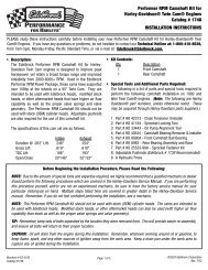
13.Rotate engine until timing marks are aligned as shown in Figure 1.<br />
14.Remove cam sprocket bolt, washer, and fuel pump eccentric. Slide<br />
sprocket and timing chain <strong>for</strong>ward to remove.<br />
15.Remove thrust plate and camshaft. Using appropriate gear puller,<br />
remove crank sprocket.<br />
VALVE SPRINGS<br />
CAUTION: WARNINGS ABOUT YOUR WARRANTY<br />
In order <strong>for</strong> this <strong>Torker</strong>-Plus cam and lifter kit to be covered under<br />
ANY WARRANTY you MUST use the correct <strong>Edelbrock</strong> Sure Seat<br />
Valve Springs. Failure to install new <strong>Edelbrock</strong> valve springs with<br />
your new <strong>Torker</strong>-Plus cam could cause the cam lobes to wear excessively<br />
and could cause additional engine damage.<br />
1. This camshaft is designed to function with <strong>Edelbrock</strong> Sure Seat valve<br />
springs #5722. Do not use dual valve springs with this camshaft.<br />
Special H.P. retainers may be necessary with your installation <strong>for</strong><br />
proper spring height. Do not use rotator type valve springs or retainers<br />
<strong>for</strong> this application.<br />
LIFTERS<br />
1. New lifters must be used with new camshaft. Use only the high rev<br />
lifters supplied with this kit. Do not pump-up lifters prior to installation!<br />
This may cause piston-to-valve interference, etc.<br />
2. Check to be sure that all lifters fit freely in the lifter bores and that<br />
the factory did not install oversized lifters in your block to compensate<br />
<strong>for</strong> machining errors.<br />
INSTALLATION INSTRUCTIONS<br />
1. Coat cam lobes and bottoms of each lifter with MoS2 lube (supplied)<br />
to prevent cam lobe and lifter wear from occurring during initial<br />
start-up.<br />
2. Install new camshaft with new sprockets, timing chain and lifters.<br />
CAUTION: Use <strong>Edelbrock</strong> Per<strong>for</strong>mer-Plus True Rolling Timing Chain<br />
and Steel Gear Set #7811 or #7820, or Accu-Drive gear drive set<br />
#7892. Do not use late model timing chain & gear sets that are<br />
designed in a retarded position and are not recommended <strong>for</strong> this<br />
camshaft installation. <strong>Edelbrock</strong> Timing Sets feature three keyways<br />
<strong>for</strong> specific timing selection. Use locking compound material on the<br />
bolt threads holding timing gear to cam. Torque to factory recommendations<br />
specified in motor repair manual. Install camshaft with<br />
timing marks lined up as recommended by factory specifications.<br />
See Figure 1. When using Per<strong>for</strong>mer-Plus Timing Chain and Gear<br />
Sets (7800 series) with <strong>Edelbrock</strong> cam and lifter kits, straight up timing<br />
alignment is achieved. If any other timing gear set is used, it is<br />
necessary to check cam position <strong>for</strong> correct timing alignment. This<br />
requires indexing the camshaft with a degree wheel to verify timing<br />
alignment. O.E.M. or non-<strong>Edelbrock</strong> timing gear sets are not recommended<br />
<strong>for</strong> use with <strong>Edelbrock</strong> camshafts.<br />
INSTALLING PUSHRODS AND ROCKER ARMS<br />
High per<strong>for</strong>mance pushrods and rocker arms and studs are recommended<br />
<strong>for</strong> this installation.<br />
After the cam is installed and timed correctly (see Figure 1), it will be<br />
necessary to check each pushrod <strong>for</strong> correct lifter pre-load.<br />
VALVE ADJUSTMENT<br />
1. Turn the engine over until the No. 1 cylinder exhaust lifter starts to<br />
move up. At this point install adjusting nut on intake rocker arm and<br />
adjust to zero clearance between rocker arm and valve tip. From this<br />
point turn adjusting nut down (clockwise) 1/4 turn more <strong>for</strong> final<br />
adjustment.<br />
2. Turn the engine over again until the intake lifter just stops coming<br />
down. At this point install adjusting nut on exhaust rocker arm and<br />
adjust to zero clearance between rocker arm and valve tip. From this<br />
point turn adjusting nut down (clockwise) 1/4 turn more <strong>for</strong> final<br />
adjustment.<br />
3. The above procedure assures correct hydraulic lifter pre-load. Repeat<br />
this procedure <strong>for</strong> each of the other seven cylinders.<br />
4. Re-install front cover, fuel pump, water pump, and oil pan using new<br />
gaskets.<br />
5. Install intake manifold using new gasket set and torque bolts to 18-<br />
22 ft./lbs. End bolts on early non-supported heads should be hand<br />
tightened only with a short wrench.<br />
6. Install crankshaft dampener and torque to factory specification.<br />
INSTALLING DISTRIBUTOR AND TIMING ENGINE<br />
NOTE: Be<strong>for</strong>e installing your distributor, check the gear drive on the<br />
distributor and oil pump <strong>for</strong> any signs of wear. If worn, be sure to<br />
replace with new or you may wear out your camshaft prematurely.<br />
This is especially true when rebuilding your engine and a high per<strong>for</strong>mance<br />
oil system is used, which generates a heavier load on the<br />
camshaft gear system. <strong>Edelbrock</strong> camshafts are designed to use<br />
OEM-type gears only.<br />
1. Turn the engine over in the direction of rotation until the No. 1 intake<br />
valve closes and continue until the pointer on the front cover is<br />
approximately 5 degrees BTDC.<br />
2. Re-install the distributor with the rotor pointing towards No. 1 terminal<br />
in the cap, and with the vacuum advance canister in its original<br />
position.<br />
3. Lightly tighten the hold-down clamp so that the distributor can still be<br />
turned to determine final setting using a timing light with the engine<br />
running.<br />
4. Replace valve covers, carburetor linkage and remaining vacuum and<br />
electrical connections.<br />
5. Re-install air conditioner, if so equipped.<br />
6. Re-fill radiator with coolant and re-connect battery.<br />
7. Double check all connections, fuel lines, etc. be<strong>for</strong>e starting engine.<br />
CAMSHAFT/LIFTER RUN-IN<br />
CAUTION: Change the engine oil and filter be<strong>for</strong>e start-up and again<br />
after the initial break-in. Do not allow the engine to run under<br />
1500 rpm <strong>for</strong> the first 1/2 hour. Vary engine speed between 1500<br />
and 2500 rpm. Slow idle speeds may result in severe cam and lifter<br />
wear.<br />
1. Start the engine and bring to break-in rpm.<br />
©2009 <strong>Edelbrock</strong> Corp. Rev. 5/09 - AJ/mc<br />
Part #<strong>5022</strong> page 2<br />
Brochure #63-<strong>5022</strong>
IMPORTANT INSTRUCTIONS AFFECTING YOUR WARRANTY<br />
CAM LOBE WEAR- Cam lobe wear is almost non-existent unless<br />
mismatched parts are used or installation of the cam and lifters is<br />
done improperly. Most cam damage is caused by the timing gear<br />
coming loose due to improper torque on bolt. Bolts holding gear to<br />
camshaft should be torqued carefully and a locking compound<br />
applied to threads of bolts.<br />
CAM GEARS AND CAMSHAFT END PLAY- If cam gear becomes<br />
loose, the cam will slide back in the block, causing the lifters to hit<br />
the lobes next to them and also the cam bearing journals. If the<br />
engine is run after this happens, the bottom of the lifters and the<br />
sides of the lobes will become clipped.<br />
When installing a camshaft, it is always important to check <strong>for</strong> proper<br />
operating clearances, especially when high per<strong>for</strong>mance components<br />
are used. Things to look <strong>for</strong> that can cause failure and damaged<br />
parts are as follows:<br />
1. Improper valve-to-piston clearance (this should be no less than<br />
0.080").<br />
2. Rocker arm stud slot clearance (both ends; valve closed and open).<br />
3. Proper spring settings (see dimensions with spring instruction sheet;<br />
correct dimensions mean maximum per<strong>for</strong>mance and longer engine<br />
life).<br />
SPECIAL INSTRUCTIONS<br />
With the <strong>Edelbrock</strong> manifold and camshaft package plus a header<br />
installation, a carburetor jet change may be required <strong>for</strong> best per<strong>for</strong>mance.<br />
Due to the varied applications of year and model of vehicles,<br />
no one combination could suffice <strong>for</strong> all installations. The following<br />
procedure is only a guideline and in many cases, the manufacturing<br />
specifications <strong>for</strong> recommended carburetors or timing may be best.<br />
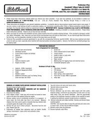
<strong>Edelbrock</strong><br />
Timing Sets<br />
feature three<br />
keyways <strong>for</strong><br />
specified timing<br />
selection.<br />
Figure 1<br />
Timing Chain<br />
Sprocket Alignment<br />
IGNITION TIMING<br />
Ignition timing <strong>for</strong> this package may vary with each application. A<br />
good starting figure would be between 10 degrees to 14 degrees initial<br />
timing at idle with vacuum advance disconnected. Total advance<br />
should not exceed 32 degrees to 34 degrees with initial and centrifugal<br />
weights combined and should be at full advance at 3000-3500<br />
rpm. After timing is adjusted, re-connect the vacuum advance line.<br />
NOTE: The best combination <strong>for</strong> any particular vehicle or application<br />
must be determined by trial and error using the above in<strong>for</strong>mation as<br />
a guideline.<br />
HEADERS<br />
For best per<strong>for</strong>mance, headers are recommended. For this application,<br />
they should be 1-5/8" or 1-3/4" diameter, approximately 31"<br />
long and terminating into a 3" collector. The remainder of the<br />
exhaust system should consist of dual exhaust and tail pipes, at least<br />
2" diameter with low back-pressure mufflers.<br />
WARNING<br />
In order <strong>for</strong> this <strong>Torker</strong>-Plus cam and lifter kit to be covered under<br />
ANY WARRANTY you MUST use the correct <strong>Edelbrock</strong> Sure Seat<br />
Valve Springs. The end flap or label from your Sure Seat Valve Spring<br />
box must be sent in with your camshaft warranty card.<br />
Failure to install new <strong>Edelbrock</strong> Sure Seat Valve Springs with your<br />
new <strong>Torker</strong>-Plus cam and lifter kit could cause the cam lobes to<br />
wear excessively and could cause additional engine damage. IF YOU<br />
HAVE ANY QUESTIONS ABOUT THIS APPLICATION, PLEASE CONTACT<br />
OUR TECHNICAL DEPARTMENT IMMEDIATELY.<br />
CAUTION: Use <strong>Edelbrock</strong> Per<strong>for</strong>mer-Plus Timing Chain and Gear Set<br />
#7811 or #7820, or Accu-Drive gear drive #7892. Do not use late<br />
model timing chain and gear sets that are designed <strong>for</strong> emissioncontrolled<br />
engines. These timing sets are machined in a retarded<br />
position and are not recommended <strong>for</strong> this camshaft installation.<br />
<strong>Edelbrock</strong> Timing Sets feature three keyways <strong>for</strong> specific timing<br />
selection.<br />
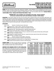
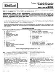
Figure 2<br />
10<br />
TC<br />
10<br />
20<br />
30<br />
1 2 3 4<br />
2<br />
6 4<br />
3<br />
5<br />
7 1<br />
8<br />
5 6 7 8<br />
Timing Marks Firing Order 1-5-4-2-6-3-7-8<br />
289-302 c.i.d. Ford V8.Turn distributor<br />
clockwise to advance timing.<br />
NOTE: 5.0 Litre H.O. engines originally have a different firing order. This<br />
must be changed to the firing order listed above when installing <strong>Torker</strong>-<br />
Plus camshaft #<strong>5022</strong>.<br />
©2009 <strong>Edelbrock</strong> Corp. Rev. 5/09- AJ/mc<br />
Part #<strong>5022</strong><br />
page 3<br />
Brochure #63-<strong>5022</strong>
<strong>Edelbrock</strong> Corporation • 2700 Cali<strong>for</strong>nia St. Torrance, CA 90503<br />
Tech-Line: 1-800-416-8628 E-Mail: <strong>Edelbrock</strong>@<strong>Edelbrock</strong>.com<br />
©2009 <strong>Edelbrock</strong> Corp. Rev. 5/09- AJ/mc<br />
Part #<strong>5022</strong> Brochure #63-<strong>5022</strong>
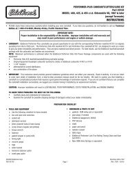
CAMSHAFT: <strong>Torker</strong>-Plus Hydraulic<br />
PART #<strong>5022</strong><br />
ENGINE: Ford 289-302 c.i.d. V8<br />
RPM RANGE: 2500-6500<br />
CAUTION: Do not use dual valve springs. Use only<br />
recommended <strong>Edelbrock</strong> Sure Seat Valve Springs #5722.<br />
Use stock ratio (1.6:1) rocker arms only.<br />
Duration at .004" Lift: Intake 280° Exhaust 290°<br />
Duration at .050" Lift: Intake 214° Exhaust 224°<br />
Lift at cam: Intake .295" Exhaust .310"<br />
Lift at valve: Intake .472" Exhaust .496"<br />
Timing at .050 Lift:<br />
Open Close<br />
Intake 0° BTDC 34° ABDC<br />
Exhaust 49° BBDC 5° BTDC<br />
CAUTION: Use <strong>Edelbrock</strong> Per<strong>for</strong>mer-Plus Timing Chain and Gear<br />
Set #7811 or #7820, or Accu-Drive gear drive #7892. Do not use<br />
late model timing chain and gear sets that are designed <strong>for</strong> emission-controlled<br />
engines. These timing sets are machined in a<br />
retarded position and are not recommended <strong>for</strong> this camshaft<br />
installation. <strong>Edelbrock</strong> Timing Sets feature three keyways <strong>for</strong> specified<br />
timing selection.<br />
©2009 <strong>Edelbrock</strong> Corp. Rev. 5/09 - AJ/mc<br />
Part #<strong>5022</strong> Brochure #63-<strong>5022</strong>C<br />
CAMSHAFT: <strong>Torker</strong>-Plus Hydraulic<br />
PART #<strong>5022</strong><br />
ENGINE: Ford 289-302 c.i.d. V8<br />
RPM RANGE: 2500-6500<br />
CAUTION: Do not use dual valve springs. Use only<br />
recommended <strong>Edelbrock</strong> Sure Seat Valve Springs #5722.<br />
Use stock ratio (1.6:1) rocker arms only.<br />
Duration at .004" Lift: Intake 280° Exhaust 290°<br />
Duration at .050" Lift: Intake 214° Exhaust 224°<br />
Lift at cam: Intake .295" Exhaust .310"<br />
Lift at valve: Intake .472" Exhaust .496"<br />
Timing at .050 Lift:<br />
Open Close<br />
Intake 0° BTDC 34° ABDC<br />
Exhaust 49° BBDC 5° BTDC<br />
CAUTION: Use <strong>Edelbrock</strong> Per<strong>for</strong>mer-Plus Timing Chain and Gear<br />
Set #7811 or #7820, or Accu-Drive gear drive #7892. Do not use<br />
late model timing chain and gear sets that are designed <strong>for</strong> emission-controlled<br />
engines. These timing sets are machined in a<br />
retarded position and are not recommended <strong>for</strong> this camshaft<br />
installation. <strong>Edelbrock</strong> Timing Sets feature three keyways <strong>for</strong> specified<br />
timing selection.<br />
©2009 <strong>Edelbrock</strong> Corp. Rev. 5/09 - AJ/mc<br />
Part #<strong>5022</strong> Brochure #63-<strong>5022</strong>C