97383, 97384, 97385, 97386, 97387, 97443, 97453 ... - Edelbrock
97383, 97384, 97385, 97386, 97387, 97443, 97453 ... - Edelbrock
97383, 97384, 97385, 97386, 97387, 97443, 97453 ... - Edelbrock

You also want an ePaper? Increase the reach of your titles
YUMPU automatically turns print PDFs into web optimized ePapers that Google loves.
®<br />
Part #<strong>97383</strong>, <strong>97384</strong>, <strong>97385</strong>, <strong>97386</strong>, <strong>97387</strong>, <strong>97443</strong>, <strong>97453</strong><br />
Rev. 5/11 - AJ/mc Page 1 of 2<br />
HYDRAULIC ROLLER LIFTER KITS<br />
Part #<strong>97383</strong>, <strong>97384</strong>, <strong>97385</strong>, <strong>97386</strong>, <strong>97387</strong>,<br />
97423, 97433, <strong>97443</strong> & <strong>97453</strong><br />
INSTALLATION INSTRUCTIONS<br />
PLEASE study these instructions carefully before beginning this installation. Most installations can be accomplished with common tools and<br />
procedures. However, you should be familiar with and comfortable working on your vehicle. If you do not feel comfortable performing this installation,<br />
it is recommended to have the installation completed by a qualified mechanic. If you have any questions, please call our Technical Hotline at:<br />
1-800-416-8628, 7:00 am - 5:00 pm, Pacific Standard Time, Monday - Friday.<br />
IMPORTANT NOTE: Proper installation is the responsibility of the installer. Improper installation<br />
will void your warranty and may result in poor performance and engine or vehicle damage.<br />
DESCRIPTION: These precision hydraulic roller lifter kits are the perfect match for <strong>Edelbrock</strong> Performer-Plus and Performer RPM hydraulic roller<br />
camshafts. They may also be used with other manufacturer’s roller camshafts. Retrofit kits are for engines not originally equipped with a hydraulic<br />
roller camshaft and lifters. These kits contain eight (8) hydraulic roller lifter assemblies, consisting of one intake and one exhaust lifter connected with<br />
a tie bar. Replacement kits offer sixteen (16) or individual lifters to replace OEM lifters in engines originally equipped with hydraulic roller camshafts.<br />
Replacement kits will require the factory guide system. See Applications below for details.<br />
APPLICATIONS:<br />
<strong>97383</strong> / 97423: Retrofit Kit. Small Block Chevrolet, 1986-earlier.<br />
<strong>97384</strong>: OEM Replacement Kit. Contains 16 lifters. Small Block Chevrolet, 1987-later.<br />
NOTE: Requires factory guide system or <strong>Edelbrock</strong> Lifter Installation Kit #<strong>97386</strong>.<br />
<strong>97385</strong>: OEM Replacement Lifter. Single replacement lifter. Small Block Chevrolet, 1987-later.<br />
NOTE: Requires factory guide system or <strong>Edelbrock</strong> Lifter Installation Kit #<strong>97386</strong>.<br />
<strong>97386</strong>: Lifter Installation Kit. Small Block Chevrolet, 1987-Later. Includes lifter hold-down spider, hold-down bolts, and lifter guides.<br />
NOTE: See Page 2 for Installation Procedure.<br />
<strong>97387</strong>: Lifter Installation Kit. Big Block Chevrolet, 1990-Later. Includes lifter hold-down spider, hold-down bolts, and lifter guides.<br />
NOTE: See Page 2 for Installation Procedure.<br />
<strong>97443</strong> / 97433: Retrofit Kit. Big Block Chevrolet (Mark IV), 1990-earlier.<br />
NOTE: Shorter than stock pushrods are required to retrofit these lifters.<br />
<strong>97453</strong>: Retrofit Kit. Small Block Ford, 1962-1987 302 C.I.D. & 1969-1993 351 C.I.D. Windsor (351W).<br />
NOTE: Shorter than stock pushrods are required to retrofit these lifters.<br />
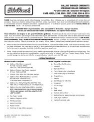
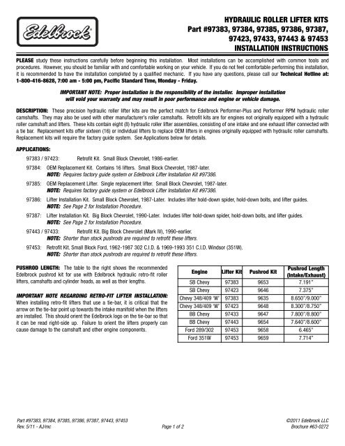
PUSHROD LENGTH: The table to the right shows the recommended<br />
<strong>Edelbrock</strong> pushrod kit for use with <strong>Edelbrock</strong> hydraulic retro-fit roller<br />
lifters, camshafts and cylinder heads, as well as their lengths.<br />
IMPORTANT NOTE REGARDING RETRO-FIT LIFTER INSTALLATION:<br />
When installing retro-fit lifters that use a tie-bar, it is critical that the<br />
arrow on the tie-bar point up towards the intake manifold when the lifters<br />
are installed. This should orient the <strong>Edelbrock</strong> logo on the tie-bar so that<br />
it can be read right-side up. Failure to orient the lifters properly can<br />
cause damage to the camshaft and other engine components.<br />
Engine Lifter Kit Pushrod Kit<br />
Pushrod Length<br />
(Intake/Exhaust)<br />
SB Chevy <strong>97383</strong> 9653 7.191”<br />
SB Chevy 97423 9646 7.375”<br />
Chevy 348/409 ‘W’ <strong>97383</strong> 9635 8.650”/9.000”<br />
Chevy 348/409 ‘W’ 97423 9648 8.300”/8.750”<br />
BB Chevy 97433 9647 7.800”/8.800”<br />
BB Chevy <strong>97443</strong> 9654 7.640”/8.600”<br />
Ford 289/302 <strong>97453</strong> 9658 6.465”<br />
Ford 351W <strong>97453</strong> 9659 7.714”<br />
©2011 <strong>Edelbrock</strong> LLC<br />
Brochure #63-0272
NOTE: To achieve proper lifter pump up, it is critical that<br />
both the oil and oil filter in the engine are changed prior to<br />
installing your new lifters. Install the lifters using a high quality<br />
engine oil (5W30 or 10W30). Briefly dip the lifters in fresh, clean oil<br />
just before installation. Do not soak the lifters for a long period of<br />
time before installation.<br />
When installing retrofit hydraulic roller lifters, make sure the guide<br />
bar faces the opposite side of the block. (Example: If facing the front<br />
of the engine, lifters being installed on the left side, should have<br />
guidebars facing the right side of the block).<br />
Roller camshafts in 1986-earlier Chevrolet engines require a Thrust<br />
Button to control camshaft end play. Check camshaft end play with<br />
the timing cover and timing cover gasket in place. End play should<br />
be kept between .005” and .008”. Check end play without the roller<br />
lifters installed. If end play is excessive, a thinner timing cover<br />
gasket may be used to correct end play. Sheet metal covers should<br />
use a waterpump with a cam-stop to prevent timing cover flex.<br />
Most Ford engines use a thrust plate to control end play, and do not<br />
require the use of a thrust button. Check end play clearance<br />
according to factory specifications.<br />
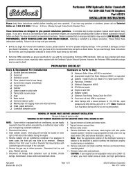
1. If using lifter installation kit <strong>97386</strong> or <strong>97387</strong>, install the lifters using<br />
the supplied lifter guides to line up the lifters.<br />
2. Install the lifter hold down spider over the lifter guides. Make sure<br />
each tab on the spider contacts the center of each lifter guide.<br />
3. Secure the lifter hold down spider to the lifter valley using the three<br />
supplied hold down bolts. Torque bolts to 18 ft./lbs.<br />
4. Adjust lifter preload as described in the “Installation Notes” section<br />
on Page 1.<br />
INSTALLATION NOTES<br />
LIFTER INSTALLATION KIT: INSTALLATION PROCEDURE<br />
<strong>Edelbrock</strong> LLC • 2700 California St. Torrance, CA 90503<br />
Tech Line: 800-416-8628 Office Line: 310-781-2222<br />
Part #<strong>97383</strong>, <strong>97384</strong>, <strong>97385</strong>, <strong>97386</strong>, <strong>97387</strong>, <strong>97443</strong>, <strong>97453</strong><br />
Rev. 5/11 - AJ/mc Page 2 of 2<br />
Refer to a service manual for your particular application or see<br />
instructions for the camshaft being used for directions on removal<br />
and installation of lifters. These lifters do not replace original flat<br />
tappet lifters, and may only be used with hydraulic roller camshafts.<br />
When installing these lifters on Ford 289-302 engines, the cylinder<br />
heads must be removed to gain enough clearance to install the<br />
lifters. Refer to a factory service manual for your particular<br />
vehicle/engine for cylinder head removal instructions.<br />
Hydraulic roller lifters require adjusting the lifter preload. Adjustable<br />
rocker arms or pushrods are required. Adjustable roller rocker arms<br />
are recommended. Hand rotate the engine until the #1 cylinder is at<br />
TDC firing position (Both #1 lifters are down in the lifter bores). You<br />
may now adjust intake and exhaust preload on that cylinder as<br />
follows: You need to set rockers at zero lash. While tightening the<br />
rocker nut, spin the pushrod, when you feel resistance, you are at<br />
zero lash. Tighten rocker nut three quarters to one full turn past zero<br />
lash. Adjust lifter preload one cylinder at a time. Rotate the engine<br />
90° until the next cylinder in the firing order is at TDC and adjust<br />
lifter preload as described above. Continue this process until all<br />
cylinders are adjusted.<br />
Figure 2 - Lifter Installation Kit, Installed<br />
®<br />
©2011 <strong>Edelbrock</strong> LLC<br />
Brochure #63-0272