Performer RPM Camshaft Kit For Harley - Edelbrock
Performer RPM Camshaft Kit For Harley - Edelbrock
Performer RPM Camshaft Kit For Harley - Edelbrock

Create successful ePaper yourself
Turn your PDF publications into a flip-book with our unique Google optimized e-Paper software.
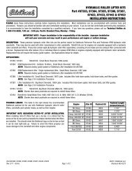
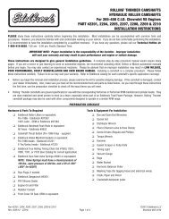
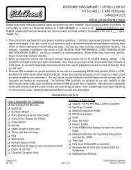
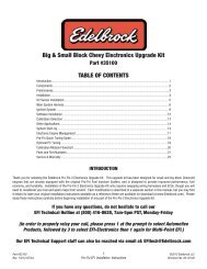
• Description:<br />
The <strong>Edelbrock</strong> <strong>Performer</strong> <strong>RPM</strong> <strong>Camshaft</strong> <strong>Kit</strong> for <strong>Harley</strong>-<br />
Davidson Twin Cam engines is designed to improve peak<br />
horsepower yet retain a broad torque range and improved<br />
rideability from 2800-6000+ <strong>RPM</strong>. Used in the <strong>Edelbrock</strong><br />
<strong>Performer</strong> <strong>RPM</strong> Power Package, these cams have supported<br />
over 100hp at the wheels on a 95” Twin Cam. They are<br />
intended to be used with <strong>Edelbrock</strong> heads, modified stock<br />
heads, or other aftermarket heads that have higher air flow<br />
capability as well as the proper valve springs and valve<br />
geometry. The <strong>Performer</strong> <strong>RPM</strong> <strong>Camshaft</strong> <strong>Kit</strong> should not be<br />
used with stock (OEM) cylinder heads. Adjustable pushrods<br />
are also required for the use of this camshaft kit.<br />
The specifications of this cam set are as follows:<br />
Intake Exhaust<br />
Duration @ .053” Lift: 246° 254°<br />
Gross Lift: .619” .619”<br />
TDC Lift: .188” .193”<br />
Open/Close: 20°/46° 52°/22°<br />
Brochure # 63-0185<br />
Catalog #1748<br />
®<br />
Page 1 of 5<br />
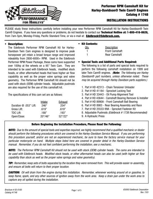
<strong>Performer</strong> <strong>RPM</strong> <strong>Camshaft</strong> <strong>Kit</strong> for<br />
<strong>Harley</strong>-Davidson® Twin Cam® Engines<br />
Catalog # 1748<br />
INSTALLATION INSTRUCTIONS<br />
PLEASE study these instructions carefully before installing your new <strong>Performer</strong> <strong>RPM</strong> <strong>Camshaft</strong> <strong>Kit</strong> for <strong>Harley</strong>-Davidson® Twin<br />
Cam® Engines. If you have any questions or problems, do not hesitate to contact our Technical Hotline at: 1-800-416-8628,<br />
from 7am-5pm, Monday-Friday, Pacific Standard Time, or via e-mail at: <strong>Edelbrock</strong>@<strong>Edelbrock</strong>.com.<br />
<strong>Kit</strong> Contents:<br />
Qty. Description<br />
1 Front <strong>Camshaft</strong><br />
1 Rear <strong>Camshaft</strong><br />
Special Tools and Additional Parts Required:<br />
The following is a list of parts and special tools required to<br />
perform the following camshaft installation on 1999 and<br />
later Twin Cam® engines. (Note: The following are <strong>Harley</strong><br />
Davidson® part numbers, unless otherwise noted. These<br />
may be acquired through <strong>Harley</strong> Davidson parts suppliers.)<br />
1. Part # HD 42313 - Chain Tensioner Unloader<br />
2. Part # HD 41184 - Sprocket Locking Tool<br />
3. Part # HD 33443 - Oil Pump Alignment Tool<br />
4. Part # HD 43644 - <strong>Camshaft</strong> Bearing Remover & Installer<br />
5. Part # HD 8990A - Front <strong>Camshaft</strong> Ball Bearing<br />
6. Part # HD 8983 - Rear Bearing Assembly and Race<br />
7. Part # HD 25533-99A - Sprocket Fastener <strong>Kit</strong><br />
8. Adjustable Pushrods (<strong>Edelbrock</strong> # 1738 Recommended)<br />
9. A Hydraulic Press<br />
Before Beginning the Installation Procedure, Please Read the Following:<br />
NOTE: Due to the amount of special tools and expertise required, we highly recommend that a qualified mechanic or dealer<br />
should perform the following procedures which are covered in the <strong>Harley</strong>-Davidson Service Manual. If you are performing<br />
this procedure yourself, and/or are not an experienced mechanic, be sure to have the factory service manual for your<br />
particular motorcycle on hand. Multiple steps listed here are covered in greater detail in the <strong>Harley</strong>-Davidson Service<br />
manual. Remember, if you do not feel confident performing the installation, see a mechanic.<br />
NOTE: The <strong>Performer</strong> <strong>RPM</strong> <strong>Camshaft</strong> <strong>Kit</strong> should not be used with stock (OEM) cylinder heads. The cams are intended to<br />
be used with <strong>Edelbrock</strong> heads. Modified stock heads, or other aftermarket heads can also be used (with higher air flow<br />
capability than stock as well as the proper valve springs and valve geometry).<br />
TIP: Remember, keep sets of bolts separated by the location they were removed from. This will provide easier re-assembly,<br />
and ensure all bolts will return to their proper location.<br />
CAUTION: Oil will drain from the engine during this installation. Remember, whenever working around oil or gasoline, to<br />
keep flame, spark, and any other sources of ignition away from the work area. Keep a drain pan under the work area to<br />
capture any oil spilled during the installation.<br />
©2003 <strong>Edelbrock</strong> Corporation<br />
Rev. 7/03
1. Disconnect the battery, and remove the fuel tank.<br />
2. On engines with the oil tank above the engine, drain the<br />
engine oil.<br />
3. Remove the front exhaust pipe to clear the Cam Housing<br />
Cover.<br />
4. Remove the Rocker Covers and remove the four 5/16”<br />
bolts and the two 1/4” bolts holding the rocker arms in<br />
place. With the rocker arms removed, remove the stock<br />
pushrods.<br />
5. Remove the push rod tube retaining clips and push rod<br />
tubes.<br />
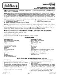
6. At this point, you may remove the lifter covers and take the<br />
lifters out, or you can make a lifter holding tool from a<br />
binder clip as shown in Figure 1.<br />
Brochure # 63-0185<br />
Catalog #1748<br />
Use wire from<br />
Binder Clip to<br />
hold lifters.<br />
INSTALLATION PROCEDURE<br />
Figure 1<br />
7. On pre-2000 models with a cam position sensor, you may<br />
want to remove the inspection cover, unplug the wires, and<br />
remove the sensor at this time to ease installation later on.<br />
8. Remove the cam housing cover keeping the bolts in a<br />
separate cup. (Note: Oil will run out of the cam housing.)<br />
9. Mark your timing chain with a paint pen or marker in order<br />
to keep the proper direction facing out.<br />
10. Using the Chain Tensioner Unloader Tool, unload pressure<br />
on the outside chain tensioner, and pin it in place with the<br />
retaining pin (See Figure 2).<br />
11. With the Sprocket Locking Tool in place, remove both<br />
sprocket retaining bolts (See Figure 3).<br />
12. Remove chain and sprockets. Remove the chain guide.<br />
13. Keeping your bolts separated, you are now ready to<br />
remove the bolts holding the oil pump and cam support<br />
plate assembly.<br />
Page 2 of 5<br />
Figure 2<br />
14. With all bolts removed, remove the cam support plate and<br />
camshaft assembly. (Note: Be careful the oil pump rotors<br />
do not fall out. Remove support plate with care, and make<br />
sure the oil pump rotors are still in place after removal. If<br />
the rotors fall out, see your Factory Service Manual for<br />
assembly procedures.)<br />
15. After removing the cam support plate, clean it thoroughly,<br />
and using the Chain Tensioner Unloader, retract the<br />
Secondary Cam Chain Tensioner, and pin it in place (See<br />
Figure 4). Mark the<br />
Secondary Cam Chain<br />
with a paint pen or<br />
marker to note which<br />
direction is facing out.<br />
Keeping the bolts<br />
separate, you can now<br />
remove the four #20<br />
Torx screws holding the<br />
Cam Bearing Retaining<br />
Plate.<br />
Figure 3<br />
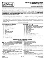
16. Place the Cam Support Plate/<strong>Camshaft</strong> assembly into a<br />
press. Using the the <strong>Camshaft</strong>/Bearing Remover and<br />
Installer, along with the proper support blocks, press the<br />
cams & bearings out of the support plate (See Figure 5).<br />
(Tip: Lightly heating the support plate around the bearing<br />
area can help ease the cams out of the support plate.)<br />
Hydraulic Press<br />
Cam Driver<br />
Support Blocks<br />
Sprocket<br />
Locking<br />
Tool<br />
Figure 5<br />
Figure 4<br />
©2003 <strong>Edelbrock</strong> Corporation<br />
Rev. 7/03
17. Retain the snap ring from the front camshaft. Set the snap<br />
ring and cam chain aside. Now is a good time to inspect<br />
the chain tensioners for wear. See the factory service<br />
manual for acceptable wear limits.<br />
18. Using the the <strong>Camshaft</strong>/Bearing Remover and Installer and<br />
proper support blocks (See Figure 6), press the new cam<br />
bearings into the cam support plate. (Note: Make sure<br />
the front cam bearing is installed letter-side up, facing the<br />
cam. Warming the support plate, and freezing the<br />
bearings can reduce the force needed to press the<br />
bearings into<br />
the support<br />
plate.) You will<br />
now be able to<br />
slip the rear<br />
bearing o-ring<br />
over the rear<br />
cam. Slide the<br />
thrust washer<br />
over the cam and over the o-ring to center the washer over<br />
the cam. Now carefully press the rear bearing race onto<br />
the rear cam, centering it over the thrust washer.<br />
19. Identify the markings on the sprockets of the <strong>Performer</strong><br />
<strong>RPM</strong> cams. Using a paint pen or marker, mark the location<br />
of these markings on the opposite side of the sprockets on<br />
the <strong>Performer</strong> <strong>RPM</strong> camshafts (See Figure 7-A). With the<br />
cam chain facing the proper direction (marked previously<br />
in Step 15), and the camshafts aligned with the markings<br />
in the proper position, use the <strong>Camshaft</strong>/Bearing Remover<br />
and Installer to press the front camshaft into the bearings<br />
in the support plate while supporting the rear camshaft<br />
(See Figure 7-B). Make sure to keep the rear camshaft<br />
parallel to the front camshaft while pressing down on the<br />
front camshaft. (Note: DO NOT FORCE the cams into the<br />
bearings. The front camshaft should press into the<br />
bearing smoothly and not bind. While pressing the front<br />
camshaft into the bearing, the rear camshaft should slide<br />
easily into the rear bearing.)<br />
Locate Punch<br />
Marks and Mark<br />
Back Side of Cams<br />
Brochure # 63-0185<br />
Catalog #1748<br />
Figure 7-A<br />
Hydraulic Press<br />
Bearing<br />
Installation Tool<br />
Support Blocks<br />
Figure 6<br />
Figure 7-B<br />
Page 3 of 5<br />
20. Verify the camshaft alignment using a straight-edge (See<br />
Figure 8). Re-install the snap ring onto the front<br />
camshaft, and check the camshaft alignment again. Reinstall<br />
the Cam Bearing Retaining Plate, making sure the<br />
threads of the Torx bolts are clean, using a drop of blue<br />
Loctite on the threads of each bolt. Torque the Torx bolts<br />
to 20-30 inch lbs. (CAUTION: Bolts can break easily,<br />
torque only to the recommended torque value.)<br />
21. With the lifters held back, replace the cam support<br />
cover/camshaft assembly making sure all o-rings, seals,<br />
and oil pump parts are in place. The assembly should<br />
slide straight in and line up smoothly onto the cover<br />
locating pins on the cam cover sealing surface. Install<br />
two cam cover bolts. HAND-TIGHTEN ONLY.<br />
22. Turn the splined end<br />
of the rear camshaft<br />
by hand to make sure<br />
the assembly spins<br />
freely. If you feel the<br />
cams interfering or<br />
rubbing on anything,<br />
remove the cam/cover<br />
assembly and check<br />
Front Cam Rear Cam<br />
Punch Marks<br />
If Clearance is<br />
Inadequate,<br />
Grind Here<br />
Figure 8<br />
Figure 9<br />
for interference with the engine case (See Figure 9, grind<br />
the area shown, only if necessary). If the clearance is<br />
sufficient, you may install the remaining cover bolts except<br />
for the four (4) bolts surounding the oil pump assembly,<br />
tightening to 90-120 inch lbs. as shown in service manual.<br />
©2003 <strong>Edelbrock</strong> Corporation<br />
Rev. 7/03
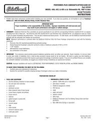
23. Install the oil pump alignment tools (See Figure 10-A)<br />
into the # 3 & 4 holes in the cam support cover, HAND<br />
TIGHT ONLY (See Figure 10-B). While rotating the engine<br />
slowly, snug down the oil pump alignment pins. Install<br />
bolts into the # 1 & 2 holes in the cam cover and tighten<br />
to 90-100 inch lbs. Remove the alignment tools and install<br />
the bolts into the # 3 & 4 holes, tighten to 90-100 inch lbs.<br />
(Note: While rotating engine, make sure oil comes out of<br />
the cam support cover. This will indicate the oil pump is<br />
properly installed.) You may now re-install the chain<br />
guide.<br />
Brochure # 63-0185<br />
Catalog #1748<br />
Oil Pump<br />
Alignment Tools<br />
Figure 10-A<br />
24. Install the crank and cam sprockets. Rotate the engine<br />
and sprocket as needed in order to line up the punch<br />
marks on the sprockets. Remember to install the cam<br />
sprocket spacer behind the cam sprocket. Leave the<br />
timing chain off at this time and do not yet remove the<br />
tensioner retaining pins.<br />
(Note: The crank sprocket bolt and washer will cover up<br />
the punch mark. Use a paint pen or marker to mark its<br />
location on the tooth of the sprocket above the punch<br />
mark. See Figure 11.)<br />
1<br />
4<br />
Mark Each<br />
Sprocket<br />
as Shown<br />
2<br />
3<br />
Figure 10-B<br />
Figure 11<br />
Page 4 of 5<br />
25. Check that the sprockets are flush with each other using a<br />
straight edge. They should be flush within .010”, as<br />
specified in your factory service manual (See Figure 12).<br />
Figure 12<br />
26. Now remove the sprockets. You may now install the chain<br />
guide and re-install the timing chain, facing the proper<br />
direction as indicated by marking the chain during<br />
removal. Using new sprocket bolts, with a drop of red<br />
Loctite on each bolt, re-install the chain and sprocket<br />
assembly. Make sure the punch marks are still aligned,<br />
and insert the Sprocket Locking Tool to prevent rotation of<br />
the sprockets while tightening the sprocket bolts. Tighten<br />
both sprocket bolts to 15 ft/lbs. Loosen both bolts one full<br />
revolution, then tighten the cam sprocket to 34 ft/lbs, and<br />
the crank sprocket to 24 ft/lbs.<br />
27. You may now remove the chain tensioner retaining pins.<br />
Using the Chain Tensioner Unloader, take tension off of the<br />
retaining pin holding the lower tensioner, and slowly let the<br />
tensioner back onto the chain. Carefully using a<br />
screwdriver, reach behind the upper tensioner, take<br />
tension off the pin, remove the pin, and slowly let the<br />
tensioner back down onto the chain.<br />
(Note: DO NOT remove pins without first relieving tension.<br />
The force exerted by the tensioner as it hits the chain can<br />
damage both the tensioner as well as the chain.).<br />
28. Re-install the cam housing cover (See Figure 13).<br />
9<br />
5<br />
1<br />
3<br />
7 6<br />
2<br />
8<br />
4<br />
10<br />
Tighten Bolts<br />
to<br />
90-120<br />
Inch Lbs.<br />
Figure 13<br />
©2003 <strong>Edelbrock</strong> Corporation<br />
Rev. 7/03
29. You are now ready to install and adjust the pushrods.<br />
Begin by making sure the pushrods are clean, and<br />
adjusted to their shortest length possible. The shorter<br />
pushrods are for the intake valves and the longer pushrods<br />
are for the exhaust.<br />
30. Insert the pushrods for one cylinder (one intake, one<br />
exhaust) into their proper locations on the rear cylinder.<br />
Do not install the pushrod tubes at this time. Rotate the<br />
engine until the lifters for the rear cam are on the base<br />
circle of the camshaft (lowest point). Install the rocker arm<br />
assembly for the rear cylinder, making sure the ball of<br />
each pushrod is in the cup of its corresponding rocker<br />
arm. Snug the rocker arm bolts to 18 ft/lbs.<br />
31. Adjust the pushrods out until all free play is taken up<br />
between the rocker arms and lifters. This is zero lash. Do<br />
not adjust beyond this point.<br />
32. Use a paint pen or marker and mark this point on the<br />
pushrods. (See Figure 14). Extend the pushrods 3-1/2<br />
turns (18 flats on the adjusting hex). Remove the rocker<br />
assembly and remove the pushrods. Make sure to keep<br />
the pushrods in order and at their current adjustment.<br />
Brochure # 63-0185<br />
Catalog #1748<br />
Mark Pushrods<br />
as Shown<br />
Figure 14<br />
Page 5 of 5<br />
Grind Ribs Shown<br />
by Arrows<br />
Figure 15<br />
Please fill out and return your warranty card. Be sure to write the part number in the “Part #____” space. Thank you.<br />
The words Twin Cam, <strong>Harley</strong>, and <strong>Harley</strong>-Davidson are registered<br />
trademarks of <strong>Harley</strong>-Davidson, Inc., Milwaukee, Wisconsin, USA, and are<br />
used in this instruction sheet for reference only.<br />
33. Using new o-rings, install the pushrod tubes. Do not<br />
extend the pushrod tubes at this time. Insert the pushrods<br />
back into their proper location. Re-install the rocker arms,<br />
tightening the bolts to 18-22 ft/lbs. Install the breather<br />
plates, tightening the 1/4” bolts to 90-100 inch lbs. You<br />
may now extend the pushrod tubes and lock into place<br />
with the pushrod tube clips.<br />
34. Coat the rocker arms in clean engine oil. Install the rocker<br />
cover (Note: You may need to grind the rocker cover for<br />
clearance, especially if using roller rockers, see<br />
Figure 15).<br />
35. Wait at least 20 minutes to let the lifters bleed down, then<br />
repeat the pushrod adjustment covered in steps 29<br />
through 34 on the front cylinder.<br />
<strong>Edelbrock</strong> Corporation, 2700 California St., Torrance, CA 90503<br />
Tech Line: 1-800-416-8628<br />
Office: 310-781-2222<br />
Tech Fax: 310-972-2730<br />
E-Mail: <strong>Edelbrock</strong>@<strong>Edelbrock</strong>.com<br />
<strong>Edelbrock</strong> is a registered trademark of <strong>Edelbrock</strong> Corporation<br />
2700 California St., Torrance, CA 90503, USA<br />
©2003 <strong>Edelbrock</strong> Corporation<br />
Rev. 7/03