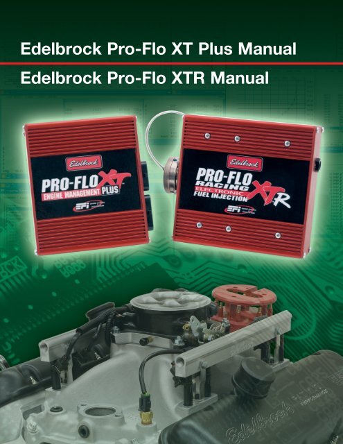
Edelbrock Pro-Flo XT Plus Manual Edelbrock Pro-Flo XTR Manual
Edelbrock Pro-Flo XT Plus Manual Edelbrock Pro-Flo XTR Manual
Edelbrock Pro-Flo XT Plus Manual Edelbrock Pro-Flo XTR Manual

You also want an ePaper? Increase the reach of your titles
YUMPU automatically turns print PDFs into web optimized ePapers that Google loves.
<strong>Edelbrock</strong> <strong>Pro</strong>-<strong>Flo</strong> <strong>XT</strong> <strong>Plus</strong> <strong>Manual</strong><br />
<strong>Edelbrock</strong> <strong>Pro</strong>-<strong>Flo</strong> <strong>XT</strong>R <strong>Manual</strong>
Table of Contents<br />
Contents<br />
Part I Introduction 11<br />
Part II EFI Basics 13<br />
1 Automotive ................................................................................................................................... Electronics Fundamentals<br />
15<br />
Basics of Electric .......................................................................................................................................................... Circuits<br />
15<br />
Injector Control .......................................................................................................................................................... Circuit<br />
18<br />
Coil Control .......................................................................................................................................................... Circuit<br />
20<br />
Relays<br />
.......................................................................................................................................................... 21<br />
5V Analog .......................................................................................................................................................... Circuits<br />
21<br />
Choosing .......................................................................................................................................................... the Right Wire Size<br />
22<br />
Fuses<br />
.......................................................................................................................................................... 23<br />
2 Fuel System ................................................................................................................................... Basics<br />
23<br />
Fuel Injector .......................................................................................................................................................... Sizing<br />
23<br />
Fuel Pump, .......................................................................................................................................................... Filter and Regulator<br />
24<br />
Fuel Rails .......................................................................................................................................................... and Lines<br />
25<br />
3 Ignition System ................................................................................................................................... Basics<br />
26<br />
Inductive .......................................................................................................................................................... Ignition Systems<br />
26<br />
Distributed .......................................................................................................................................................... Spark<br />
27<br />
Wasted Spark .......................................................................................................................................................... 29<br />
Coil on Plug .......................................................................................................................................................... 29<br />
Multiplexed .......................................................................................................................................................... Ignition<br />
30<br />
Capacitive .......................................................................................................................................................... Discharge Ignition Systems<br />
30<br />
1<br />
1
2<br />
Power to Win<br />
4 EFI Sensors ................................................................................................................................... 31<br />
Pressure Scales .......................................................................................................................................................... & Units<br />
31<br />
Engine Position .......................................................................................................................................................... 32<br />
Load<br />
.......................................................................................................................................................... 32<br />
Manifold ......................................................................................................................................................... Pressure (MAP)<br />
33<br />
Throttle ......................................................................................................................................................... Angle<br />
33<br />
Throttle Position .......................................................................................................................................................... 34<br />
Coolant Temperature<br />
.......................................................................................................................................................... 34<br />
Air Temperature .......................................................................................................................................................... 35<br />
Oxygen<br />
.......................................................................................................................................................... 35<br />
Fuel Pressure .......................................................................................................................................................... 36<br />
Oil Pressure .......................................................................................................................................................... 37<br />
5 EFI Actuators ................................................................................................................................... 38<br />
Fuel Injectors .......................................................................................................................................................... 38<br />
Ignition Coils .......................................................................................................................................................... 39<br />
Spark Plugs .......................................................................................................................................................... 39<br />
Idle Air Control .......................................................................................................................................................... Actuators<br />
40<br />
6 Terminology ................................................................................................................................... 40<br />
Part III Hardware and Wiring Installation 49<br />
1 <strong>XT</strong> <strong>Plus</strong> Pinout ................................................................................................................................... 49<br />
2 <strong>XT</strong> <strong>Plus</strong> Wiring ................................................................................................................................... 51<br />
3 <strong>XT</strong> <strong>Plus</strong> Crank ................................................................................................................................... Position Wiring<br />
63<br />
4 <strong>XT</strong>R Pinout<br />
................................................................................................................................... 69
Contents<br />
5 <strong>XT</strong>R Wiring ................................................................................................................................... 72<br />
6 Mating Connectors ................................................................................................................................... 79<br />
Part IV System Editor Software 81<br />
1 Software File ................................................................................................................................... Types and Descriptions<br />
81<br />
2 Software System ................................................................................................................................... Requirements<br />
83<br />
3 Initial Setup ................................................................................................................................... 83<br />
4 File Menu<br />
................................................................................................................................... 83<br />
Add/Replace .......................................................................................................................................................... File<br />
84<br />
Save File<br />
.......................................................................................................................................................... 85<br />
Work Offline .......................................................................................................................................................... 85<br />
Synchronize .......................................................................................................................................................... 86<br />
Register ECU's .......................................................................................................................................................... 87<br />
Importing .......................................................................................................................................................... Data<br />
88<br />
Options<br />
.......................................................................................................................................................... 89<br />
Port Settings .......................................................................................................................................................... 91<br />
User Login .......................................................................................................................................................... 92<br />
Set Password .......................................................................................................................................................... 92<br />
Printing a .......................................................................................................................................................... Map<br />
93<br />
5 Logger Menu ................................................................................................................................... 93<br />
Download .......................................................................................................................................................... Logger<br />
94<br />
Stop Download .......................................................................................................................................................... 94<br />
Auto Download .......................................................................................................................................................... 95<br />
ECU Configuration<br />
.......................................................................................................................................................... 95<br />
3<br />
3
4<br />
Power to Win<br />
Send Config .......................................................................................................................................................... 96<br />
Session Data .......................................................................................................................................................... 97<br />
Clear Fuel .......................................................................................................................................................... Counter<br />
97<br />
6 Tools Menu...................................................................................................................................<br />
98<br />
Hide File Folder .......................................................................................................................................................... 98<br />
Extract Map .......................................................................................................................................................... 99<br />
Compare .......................................................................................................................................................... Map<br />
100<br />
Edit Comments .......................................................................................................................................................... 100<br />
Read Lambda .......................................................................................................................................................... Table<br />
101<br />
Clear Lambda .......................................................................................................................................................... Data<br />
102<br />
Lambda Table .......................................................................................................................................................... 102<br />
Active Cursor .......................................................................................................................................................... 103<br />
7 Config Menu ................................................................................................................................... 104<br />
Channel Setup .......................................................................................................................................................... 104<br />
Enable Conditions<br />
.......................................................................................................................................................... 105<br />
Outing Data .......................................................................................................................................................... 106<br />
ECU Channels .......................................................................................................................................................... 107<br />
System Units .......................................................................................................................................................... 108<br />
Injector Details .......................................................................................................................................................... 108<br />
System Alarms .......................................................................................................................................................... 109<br />
8 Syscon Menu ................................................................................................................................... 110<br />
Load Hex .......................................................................................................................................................... File<br />
110<br />
Flash Loader<br />
.......................................................................................................................................................... 111
Contents<br />
Extract Config .......................................................................................................................................................... 112<br />
Monitor ADC .......................................................................................................................................................... 112<br />
System Flags .......................................................................................................................................................... 113<br />
Reset Engine .......................................................................................................................................................... Clock<br />
116<br />
9 iLink Menu ................................................................................................................................... 117<br />
Setup<br />
Connect<br />
.......................................................................................................................................................... 117<br />
.......................................................................................................................................................... 118<br />
Disconnect .......................................................................................................................................................... 118<br />
Send Map .......................................................................................................................................................... 119<br />
10 Editing Maps ................................................................................................................................... 119<br />
File Folder .......................................................................................................................................................... 120<br />
Graphic Displays<br />
.......................................................................................................................................................... 125<br />
Numeric .......................................................................................................................................................... Tables<br />
127<br />
Editing Constants<br />
.......................................................................................................................................................... 128<br />
11 Function Groups ................................................................................................................................... 129<br />
12 Fuel Injection ................................................................................................................................... Function Group<br />
129<br />
Injection .......................................................................................................................................................... Map<br />
130<br />
Injection .......................................................................................................................................................... Phase<br />
130<br />
Injection .......................................................................................................................................................... f(Battery)<br />
131<br />
Cylinder .......................................................................................................................................................... Trims<br />
132<br />
Constants .......................................................................................................................................................... 134<br />
13 Spark Advance ................................................................................................................................... Function Group<br />
135<br />
Ignition Map<br />
.......................................................................................................................................................... 135<br />
5<br />
5
6<br />
Power to Win<br />
Dwell f(Battery) .......................................................................................................................................................... 136<br />
Cylinder .......................................................................................................................................................... Trims<br />
137<br />
Constants .......................................................................................................................................................... 139<br />
14 Boost Control ................................................................................................................................... Function Group<br />
140<br />
Base Duty .......................................................................................................................................................... 140<br />
Boost Curves .......................................................................................................................................................... 141<br />
Constants .......................................................................................................................................................... 143<br />
15 Lambda Control ................................................................................................................................... Function Group<br />
144<br />
Lambda Setpoint<br />
.......................................................................................................................................................... 145<br />
Lambda Calibration<br />
.......................................................................................................................................................... 146<br />
Constants .......................................................................................................................................................... 149<br />
Constants .......................................................................................................................................................... 151<br />
16 Idle Speed ................................................................................................................................... Function Group<br />
151<br />
Speed f(Water .......................................................................................................................................................... T)<br />
152<br />
Constants .......................................................................................................................................................... 153<br />
17 Sensor Calibration ................................................................................................................................... Function Group<br />
154<br />
Temperatures .......................................................................................................................................................... 154<br />
Pressures .......................................................................................................................................................... 155<br />
Throttle<br />
.......................................................................................................................................................... 156<br />
Gear Position .......................................................................................................................................................... 158<br />
Gear Ratios .......................................................................................................................................................... 159<br />
Constants .......................................................................................................................................................... 160<br />
18 Correction ................................................................................................................................... Tables Function Group<br />
160
Contents<br />
Injection .......................................................................................................................................................... 161<br />
Spark Advance .......................................................................................................................................................... 162<br />
19 Accel/Decel ................................................................................................................................... Function Group<br />
163<br />
Accel f(Water .......................................................................................................................................................... T)<br />
163<br />
Accel f(RPM) .......................................................................................................................................................... 164<br />
Constants .......................................................................................................................................................... 166<br />
20 System Constants ................................................................................................................................... Function Group<br />
167<br />
Configuration .......................................................................................................................................................... 167<br />
21 Nitrous Control ................................................................................................................................... Function Group<br />
168<br />
Constants .......................................................................................................................................................... 169<br />
Stage Setup .......................................................................................................................................................... 170<br />
22 Engine <strong>Pro</strong>tection ................................................................................................................................... Function Group<br />
172<br />
Constants .......................................................................................................................................................... 172<br />
23 Diagnostics ................................................................................................................................... 173<br />
Clear Diagnostics<br />
.......................................................................................................................................................... 175<br />
Clear Resets .......................................................................................................................................................... 175<br />
Error Codes .......................................................................................................................................................... 175<br />
24 Creating Setups ................................................................................................................................... 177<br />
25 Hot Keys<br />
New Template .......................................................................................................................................................... 179<br />
Editing Controls .......................................................................................................................................................... 179<br />
Adding Controls .......................................................................................................................................................... 179<br />
................................................................................................................................... 181<br />
26 ECU Calibrations<br />
................................................................................................................................... 182<br />
7<br />
7
8<br />
Power to Win<br />
Part V Data Analysis Software 184<br />
1 File<br />
2 View<br />
3 Edit<br />
................................................................................................................................... 185<br />
Add New .......................................................................................................................................................... Outing<br />
186<br />
Replace Outing .......................................................................................................................................................... 187<br />
User Export .......................................................................................................................................................... 189<br />
Subset<br />
.......................................................................................................................................................... 190<br />
Setup file .......................................................................................................................................................... 191<br />
Options<br />
.......................................................................................................................................................... 192<br />
User Login .......................................................................................................................................................... 194<br />
Add New .......................................................................................................................................................... Folder<br />
195<br />
Print<br />
.......................................................................................................................................................... 196<br />
................................................................................................................................... 197<br />
Time Plot .......................................................................................................................................................... 197<br />
Distance .......................................................................................................................................................... Plot<br />
201<br />
Entire Outing .......................................................................................................................................................... 201<br />
XY Plot<br />
.......................................................................................................................................................... 202<br />
Histogram .......................................................................................................................................................... 203<br />
Measure .......................................................................................................................................................... Cursor<br />
204<br />
Event Markers .......................................................................................................................................................... 205<br />
Macro Toolbar .......................................................................................................................................................... 206<br />
................................................................................................................................... 207<br />
Channel <strong>Pro</strong>perties<br />
.......................................................................................................................................................... 207<br />
Outing Info<br />
.......................................................................................................................................................... 209
4 Data<br />
Contents<br />
Creating .......................................................................................................................................................... 210<br />
Importing .......................................................................................................................................................... 211<br />
Math Operators .......................................................................................................................................................... 212<br />
Math Functions .......................................................................................................................................................... 212<br />
Math Examples .......................................................................................................................................................... 214<br />
Creating .......................................................................................................................................................... 215<br />
Importing .......................................................................................................................................................... 216<br />
Color Pallette .......................................................................................................................................................... 216<br />
Current Calibration<br />
.......................................................................................................................................................... 217<br />
ECU Calibration<br />
.......................................................................................................................................................... 217<br />
Zero Channels .......................................................................................................................................................... 219<br />
................................................................................................................................... 220<br />
Hide File .......................................................................................................................................................... Folder<br />
220<br />
Remove Scalings .......................................................................................................................................................... 220<br />
Add New .......................................................................................................................................................... Folder<br />
221<br />
Delete Folder .......................................................................................................................................................... 221<br />
Add Outings .......................................................................................................................................................... 221<br />
Replace Outings .......................................................................................................................................................... 221<br />
Replace All .......................................................................................................................................................... Outings<br />
222<br />
Delete Outing .......................................................................................................................................................... 222<br />
Auto Update .......................................................................................................................................................... 222<br />
Tile Graphs .......................................................................................................................................................... 223<br />
5 ECU Calibrations<br />
................................................................................................................................... 223<br />
9<br />
9
10<br />
Power to Win<br />
6 Hot Keys<br />
................................................................................................................................... 225<br />
Part VI Mapping Guide 225<br />
1 Sensor Calibration ................................................................................................................................... 226<br />
2 Pickup Settings ................................................................................................................................... 226<br />
3 Distributed ................................................................................................................................... applications - Synching the Ignition Timing<br />
227<br />
4 EFI Tuning ................................................................................................................................... Strategies<br />
230<br />
5 Idle Control ................................................................................................................................... 232<br />
6 Fuel Tuning ................................................................................................................................... Requirements<br />
235<br />
7 Main fuel ................................................................................................................................... map tuning tips<br />
238<br />
8 Idle<br />
................................................................................................................................... 241<br />
9 Off-Idle & ................................................................................................................................... Slow Cruise / Low Speed & Light Load<br />
242<br />
10 Cruise & Light ................................................................................................................................... Acceleration / Medium Speeds & Loads<br />
242<br />
11 Heavy Load ................................................................................................................................... - Part Throttle<br />
242<br />
12 Wide Open ................................................................................................................................... Throttle<br />
243<br />
13 Spark Tuning ................................................................................................................................... Requirements<br />
243<br />
14 Cold Start ................................................................................................................................... and Warmup<br />
244<br />
15 Accel Function ................................................................................................................................... 244<br />
16 Suggested ................................................................................................................................... dyno mapping procedure<br />
244<br />
17 PID Tuning ................................................................................................................................... 246<br />
18 Nitrous Control ................................................................................................................................... (<strong>XT</strong> <strong>Plus</strong> Only)<br />
247<br />
19 Tuning for ................................................................................................................................... regular vs premium fuels<br />
249<br />
Index 251
1 Introduction<br />
Introduction 11<br />
Engine control in spark ignited engines means regulating fuel and air intake as well as spark<br />
timing to achieve desired performance and economy. Until recently, fully programmable<br />
engine management systems were not available to the typical enthusiast and the ones that<br />
were available, based primarily on OEM systems, were complex and cost prohibitive.<br />
<strong>Edelbrock</strong>'s <strong>Pro</strong> <strong>Flo</strong> <strong>XT</strong> <strong>Plus</strong> and <strong>XT</strong>R systems are designed for competition and ultra high<br />
performance street vehicles. The systems provide the experienced installer/tuner with a<br />
starting point for any custom application. <strong>Pro</strong> <strong>Flo</strong> <strong>XT</strong> <strong>Plus</strong> systems feature lower cost<br />
enclosures, connectors and injector drivers. They are compatible with high impedance<br />
injectors only or low impedance injectors when used in conjunction with a stand alone peak<br />
and hold injector driver box (not included). <strong>Pro</strong> <strong>Flo</strong> <strong>XT</strong>R systems feature aircraft/mil spec.<br />
style connectors as well as built-in peak and hold injector drivers.<br />
If you run into problems, you may contact our EFI Technical Hotline at 800-416-8628 from<br />
7:00 am to 5:00 pm PST Monday through Friday.<br />
<strong>Edelbrock</strong> EFI system customers can now join others at http://forums.edelbrock.com/forums/<br />
The forum offers support from current experienced users as well as <strong>Edelbrock</strong> Tech Reps.<br />
<strong>Pro</strong> <strong>Flo</strong> <strong>XT</strong> <strong>Plus</strong> and <strong>XT</strong>R System Features:<br />
Software<br />
* Live tuning<br />
* 3D fuel and spark maps<br />
* All maps with adjustable breakpoints<br />
* <strong>Pro</strong>grammable sensor calibrations<br />
* Closed loop lambda control<br />
* Unique self-mapping software<br />
* Fuel and spark trims for each cylinder<br />
* 3D injection phase map<br />
* Sensor correction tables<br />
* Closed loop boost control<br />
* ECU loadable with 2 maps<br />
* Adjustable internal logger sample rates<br />
* <strong>Pro</strong>grammable Engine <strong>Pro</strong>tection functions<br />
Outputs<br />
* 8 injector drives - Saturated (<strong>XT</strong> <strong>Plus</strong>) or Peak and Hold (<strong>XT</strong>R)<br />
* 1 coil driver (<strong>XT</strong> <strong>Plus</strong>), 4 coil drivers (<strong>XT</strong>R)<br />
* PWM Wastegate control<br />
* Lambda heater control<br />
* Nitrous control (4 stages)<br />
* Fuel pump output<br />
* Digital tach output
12<br />
Power to Win<br />
* Stepper motor (IAC 4 wire)<br />
* PWM output for IAC<br />
* Data link to data logger<br />
Digital Inputs<br />
* Engine speed (hall or mag)<br />
* Cam position (hall or mag)<br />
* Wheel speed (<strong>XT</strong>R only)<br />
Switch Inputs<br />
*Engine Kill<br />
*Beacon (or clutch switch)<br />
*Pit Switch (or master nitrous enable)<br />
*Map Select (2 unique maps possible switch on the fly)<br />
*Boost Switch (or gear position)<br />
Analog Inputs<br />
* Throttle, Battery, Airbox, Air Temp, Water Temp, Oil Temp, Fuel Press, Oil Press, Lambda<br />
1, Lambda 2, ECU Temp (internal)<br />
Diagnostics<br />
* Error codes for all sensors and pickups<br />
* <strong>Pro</strong>grammable error thresholds<br />
* Sensor Min and Max values recorded<br />
* Non-volatile logger memory (1 meg)
2 EFI Basics<br />
Introduction 13<br />
What is the motivation for electronic engine control? Is it to make more power? Better<br />
economy and drivability? Cold weather improvements? Other factors? The answer to all of<br />
these depends on the application. There are a lot of misconceptions about electronic engine<br />
control and fuel injection in general. Each of the above items is addressed individually<br />
below:<br />
More Power<br />
A fuel injection system will add power right? Not necessarily. One of the biggest myths or<br />
misconceptions customers have when researching EFI systems is that EFI systems will<br />
"increase horsepower" or "System X will make more power than System Y". There isn't<br />
anything magic about electronically controlling fuel flow or spark advance that will increase<br />
horsepower. Simply put, an engine is an air pump. The amount of power potential an engine<br />
has is in direct proportion to how much airflow is possible. That being said though, when you<br />
switch from a carbureted setup to EFI, you will usually change the intake manifold and<br />
throttle body. If the new intake and throttle body allows your engine to move more air and the<br />
right amount of fuel and timing is added into the mix, your engine will make more power. If<br />
the new manifold and throttle body reduces airflow under certain operating conditions on your<br />
engine, you will lose power...period.<br />
Since fuel suspension and vaporization is no longer an issue with EFI, manifold designers are<br />
not as limited when it comes to runner length or volume. Much longer runners can be created<br />
to increase bottom end torque without worrying about fuel dropping out of suspension.<br />
Beyond that, the job of an EFI system is to control fuel flow and ignition timing just like a<br />
carburetor and points distributor. In most cases mixture distribution can be improved reducing<br />
cylinder to cylinder power fluctuations. You will have much more flexibility with ignition<br />
timing also. There are no mechanical limitations when it comes to spark timing. Most systems<br />
use a 3 dimensional map of indicated engine load and RPM. You can command whatever<br />
spark timing you want based on the operating conditions.<br />
Better Economy and Drivability<br />
Take the example of converting an older V8 carbureted engine to fuel injection. The potential<br />
for economy and drivability improvements depends on a couple of things:<br />
· How well was the carburetor tuned to begin with?<br />
· What kind of engine is it? Stock, mildly modified, highly modified, forced induction?<br />
· What kind of camshaft is being used?<br />
Most traditional carburetors have a given range over which they can operate. There are<br />
always exceptions to the rule but for the most part, you can't expect a carburetor designed to<br />
support over 500 horsepower to be also capable of maximizing highway fuel economy. There<br />
are too many tradeoffs in carburetor design. Usually, the carburetor will be sized and tuned to<br />
make maximum horsepower. This will create an overly rich condition at light load and part<br />
throttle conditions and will hurt economy. These limitations are especially important on<br />
forced induction applications. The required fuel flow range is so large, it is extremely
14<br />
Power to Win<br />
difficult to maintain a high fuel flow rate on the top end and still be able to lean the mixture<br />
appropriately for best economy. Tuning a carburetor for use on a forced induction application<br />
is extremely difficult and usually requires custom modifications to the carburetor design and a<br />
lot of trial and error.<br />
The potential room for improvement decreases the closer you get to a stock setup, especially<br />
if the original carburetor was sized correctly for the application and tuned well. There will<br />
always be a little room for improvement but gains are harder to come by on a stock setup and<br />
it takes an experienced tuner to realize them. In fact, it's entirely possible for an<br />
inexperienced tuner to install an expensive EFI system on a formerly carbureted, stock engine<br />
and lose both power AND economy.<br />
While fuel injectors are still subject to size and flow limitations on the top end, they have<br />
much more useable range on the bottom end and allow for much more precision at low flow<br />
rates. In other words, you can size your injectors for the required horsepower range without<br />
worrying about losing resolution at idle and cruise settings. This is especially beneficial on<br />
forced induction engines.<br />
<strong>Pro</strong>per camshaft selection is always important. The right camshaft will optimize power<br />
without hurting economy. The wrong camshaft may make good power but will cause terrible<br />
emissions and fuel economy. As a rule of thumb, an EFI camshaft should have at least 112<br />
degrees of lobe separation angle to decrease overlap. EFI engines do not require as much cam<br />
overlap as carbureted engines do. In fact, too much can cause tuning problems especially on<br />
EFI systems that rely on manifold pressure sensor data for the primary indication of engine<br />
load. A lot of overlap will decrease manifold vacuum at idle and off idle (where most street<br />
vehicles spend 99.9% of their operating time). This limits the useable range of the main fuel<br />
map and makes tuning a challenge. There are tuning strategies available the rely on the TPS<br />
sensor instead of the manifold pressure sensor for load. This method is referred to as Alpha-<br />
N and avoids the resolution problem caused by low engine vacuum. The Alpha-N strategy is<br />
used primarily on racing applications and is best left to an experienced tuner.<br />
Cold Weather Performance<br />
<strong>Pro</strong>vided the camshaft and engine combination are appropriate for an EFI application, there is<br />
a lot of room for improvement in these two areas. Since the injectors are typically positioned<br />
very close to the intake valve, there is less chance of intake wall wetting in cold conditions.<br />
Sequential injection also helps to time the injector opening to the intake valve opening event.<br />
This helps get the right amount of fuel into the cylinder even when cold. Combined with a<br />
properly tuned idle air control system, cold weather starting and performance will most<br />
certainly improve with EFI.<br />
Other Factors<br />
Depending on the complexity of the system, aftermarket EFI systems can include functions to<br />
control:<br />
· Cooling fans
· Fuel pump<br />
· Nitrous<br />
· Boost control solenoids<br />
· Staged injectors<br />
EFI Basics 15<br />
Some systems also include on board data logging capabilities. This is very beneficial for<br />
racing applications. Many variables can be logged and downloaded after the race to aid in<br />
diagnostics and tuning.<br />
2.1 Automotive Electronics Fundamentals<br />
2.1.1 Basics of Electric Circuits<br />
To understand the theory of basic direct current (DC) electrical circuits, a few terms must be<br />
defined first:<br />
Volts<br />
Volts are units of electrical pressure. The symbol used for volts is V. Very small voltage<br />
values are measured in millivolts (1/1000th of a volt). Examples include the voltage output<br />
from most engine sensors. Larger voltages are measured in kilovolts (1,000 volts). Examples<br />
include the voltage required to jump a spark plug gap during the power stroke.<br />
Amps<br />
Amps or amperes are units of electron flow or how fast the electrons are passing through the<br />
conductor. The symbol for Amps is A. Smaller current flow is measured in milliamps (mA<br />
or 1/1000th of an amp)<br />
Ohms<br />
Ohms are units of electrical resistance or how much the conductor or resistor resists the flow<br />
of electrical current. The symbol for ohms is the greek letter Omega. Smaller resistances are<br />
measured in milliohms or 1/1000th of an ohm. Larger resistances are measured in megaohms<br />
or 1000 ohms.<br />
Ohm's Law<br />
Ohm's law states that the current in a circuit is directly proportional to the applied voltage and<br />
inversely proportional to the resistance in the circuit. This statement can be re-written using<br />
the following three statements:<br />
1. When the voltage goes up or down, current flow also goes up or down as long as the<br />
resistance stays the same.<br />
2. When resistance goes up, current goes down as long as the voltage stays the same.<br />
3. When the resistance goes down, current goes up as long as the voltage stays the same.<br />
An easy way to understand these concepts is to compare the movement of electricity to that of<br />
running water. Water flows through a pipe with a certain amount of pressure. The size
16<br />
Power to Win<br />
(diameter) of the pipe dictates how much resistance there will be to the flowing water. The<br />
smaller the pipe, the more resistance. You can increase the pressure to get more water to flow<br />
through, or you can increase the size of the pipe to allow more water to flow using less<br />
pressure. Since too much pressure can burst the pipe, we should probably restrict the amount<br />
of pressure being used.<br />
Voltage is analogous to water pressure. Amperage is like the amount or volume of water<br />
flowing through, while resistance is the size of the wire transmitting the current. Since too<br />
much voltage will damage the electrical components such as light bulbs and computer<br />
circuits, we must limit the amount of voltage. Too much water pressure and things could<br />
start breaking. Too much voltage and things could start overheating.<br />
There are two basic types of circuits, series and parallel. The following examples illustrate<br />
the differences and how ohm's law applies to each.<br />
The diagram above shows a typical electrical circuit. For the sake of this document, assume<br />
the current flows from the positive terminal of the battery trough each load and back to the<br />
negative terminal of the battery. The load can represent any component in the circuit that<br />
adds resistance. These can include, ignition coils, injectors, solenoids, light bulbs, etc. This<br />
type if circuit is referred to as a parallel circuit since the current flow across each load is<br />
dependent on the load. As the load resistance goes up, the current flow across that load will
EFI Basics 17<br />
go down. The total current flow the battery must provide can be represented as the sum of all<br />
the individual currents in the circuit.<br />
The diagram above represents a series circuit. A series circuit is different from a parallel<br />
circuit in that the current flow through the circuit is the same regardless of where it is<br />
measured. Also, the total resistance the battery sees can be represented by the sum of all<br />
individual load resistances.
18<br />
Power to Win<br />
2.1.2 Injector Control Circuit
EFI Basics 19<br />
The schematic above shows a typical fuel control circuit using the <strong>Pro</strong> <strong>Flo</strong> system. Power is<br />
provided to one side of each injector coil from the main relay. The relay contacts are supplied<br />
battery voltage through a 20 amp fuse. The main relay primary coil is supplied power from<br />
the battery through a 3 A fuse and the ignition switch. The ignition switch must be hot in<br />
both start and run conditions. The <strong>Pro</strong> <strong>Flo</strong> ECU controls the ground side of each injector coil<br />
along with the ground side of the main relay primary coil. To diagnose basic wiring problems<br />
in this circuit, a digital multimeter can be used to measure the voltage at the positive side of<br />
each injector (usually an orange wire). If the measurement is performed with the injector<br />
connector unplugged, the data listed in the table above will only apply to the orange wire. If<br />
the connector is plugged in, these measurements will apply to both sides of the connector.<br />
Multimeters do not respond fast enough to be used while the engine is running. Under these<br />
conditions, an oscilloscope is used to monitor the injector voltage signals. Note that these<br />
signals are only present when the connector is plugged into the injector.
20<br />
Power to Win<br />
2.1.3 Coil Control Circuit
2.1.4 Relays<br />
EFI Basics 21<br />
The schematic above shows a typical coil control circuit using the <strong>Pro</strong> <strong>Flo</strong> system. Power is<br />
provided to the coil primary from the main relay. The relay contacts are supplied battery<br />
voltage through a 20 amp fuse. The main relay primary coil is supplied power from the<br />
battery through a 3 A fuse and the ignition switch. The ignition switch must be hot in both<br />
start and run conditions. The <strong>Pro</strong> <strong>Flo</strong> ECU controls the ground side of the coil primary along<br />
with the ground side of the main relay primary coil. To diagnose basic wiring problems in<br />
this circuit, a digital multimeter can be used to measure the voltage at the positive side of the<br />
coil primary (usually a brown wire). Multimeters do not respond fast enough to be used while<br />
the engine is running. Under these conditions, an oscilloscope is used to monitor the coil<br />
primary voltage and current signals. While running power is supplied constantly to the<br />
positive side of the primary coil. The coil is said to be charging when the <strong>Pro</strong> <strong>Flo</strong> ECU<br />
grounds the negative side. During one engine cycle, the amount of time the coil is grounded<br />
can range from less than 2 milliseconds (0.002 seconds) to more than 7 milliseconds. This<br />
amount of time is called coil dwell. The sample oscilloscope trace in the diagram above<br />
shows both voltage and current traces for the coil primary.<br />
A relay is a remote control switch that uses a small amount of current to control a large<br />
amount of current. A typical relay has a control circuit called the primary coil and a power<br />
circuit called the contacts. The primary coil is fed current by the power source and the current<br />
flows through a switch and an electromagnetic coil to ground. The power circuit is also fed<br />
current from the power source and the current flows to an armature which is attracted by the<br />
magnetic force on the coil.<br />
When the primary circuit switch is open no current flows through the coil to ground. The coil<br />
is not energized. The contacts are open and no current flows to the load. When the primary<br />
circuit switch is closed, current flows to the relay and energizes the coil. The resulting<br />
magnetic field pulls the armature down closing the contacts and allowing current to flow to<br />
the load. The relay control circuit or primary can be switched from either the power supply<br />
side or the ground side.<br />
2.1.5 5V Analog Circuits<br />
Some sensors require a reference voltage to operate. Although the reference voltage can<br />
sometimes be 12 volts, most of the time, 5 volts is used. The sensor will have 3 terminals or<br />
connections:<br />
1. 5 volt high reference<br />
2. Signal<br />
3. Ground<br />
The "ground" pin is important. It is actually what's called a low reference and is supplied by<br />
the ECU. The "signal" from the sensor is measured by the ECU relative to the high and low<br />
reference voltages. The low reference is filtered inside the ECU. The ground pin from a 3<br />
wire analog sensor should never be connected to battery or chassis grounds.
22<br />
Power to Win<br />
2.1.6 Choosing the Right Wire Size<br />
Choosing the correct wire size when constructing harnesses or making circuit repairs is<br />
critical. Choosing wires too thin may limit current flow to unacceptable levels or even result<br />
in melted wires. Two size factors must be considered: wire gauge number and wire length.<br />
Wire gauge numbers are determined by the conductor's cross sectional area.<br />
In the American wire gauges (AWG) system, "gauge" numbers are assigned to wires of<br />
different thicknesses. While the gauge numbers are not directly comparable to wire diameters<br />
and cross sectional areas, higher numbers are assigned to increasingly thinner wires and lower<br />
numbers are assigned to increasingly thicker wires.<br />
The wire cross sectional area in the AWG system is measured in circular mils. A mil is a<br />
thousandth of an inch (0.001). A circular mil is the area of a circle 1 mil (0.001) in diameter.<br />
Wire length must be considered when repairing circuits because resistance increases with<br />
longer lengths. Fir example, a 16 gauge wire can carry an 18 amp load for 10 feet without<br />
excessive voltage drop. But if the section of wiring being replaced is only 3 feet long, an 18<br />
gauge wire can be used. The following table is an excerpt from the Handbook of Electronic<br />
Tables and Formulas and can be used for reference.<br />
AWG<br />
Gauge<br />
Conductor<br />
Diam (in)<br />
Maximum<br />
Current (amps)<br />
0 0.3249 245<br />
1 0.2893 211<br />
2 0.2576 181<br />
3 0.2294 158<br />
4 0.2043 135<br />
5 0.1819 118<br />
6 0.162 101<br />
7 0.1443 89<br />
8 0.1285 73<br />
9 0.1144 64<br />
10 0.1019 55<br />
11 0.0907 47<br />
12 0.0808 41<br />
13 0.072 35<br />
14 0.0641 32<br />
15 0.0571 28<br />
16 0.0508 22<br />
17 0.0453 19<br />
18 0.0403 16<br />
19 0.0359 14<br />
20 0.032 11
2.1.7 Fuses<br />
21 0.0285 9<br />
22 0.0254 7<br />
23 0.0226 4.7<br />
24 0.0201 3.5<br />
25 0.0179 2.7<br />
26 0.0159 2.2<br />
27 0.0142 1.7<br />
28 0.0126 1.4<br />
29 0.0113 1.2<br />
30 0.01 0.86<br />
31 0.0089 0.7<br />
32 0.008 0.53<br />
EFI Basics 23<br />
Fuses are the most common circuit protection device. Fuses have a fusible element, or low<br />
melting point metal strip, in a glass tube or plug-in plastic cartridge. Fuse ratings range from<br />
0.5 to 35 amps, but 3 amp to 20 amp fuses are most common.<br />
Notes<br />
1. Turn off all electrical components and the ignition switch before replacing a fuse. Do not<br />
exceed the fuse amp rating.<br />
2. Always use a fuse puller for removing and inserting a fuse. Remove and install straight in<br />
and out without twisting. Twisting could force open the terminals too much, resulting in a<br />
bad connection.<br />
2.2 Fuel System Basics<br />
2.2.1 Fuel Injector Sizing<br />
A simple formula can be used to select properly sized injectors for your application. To select<br />
the proper injector size, the required flow rate at each injector must be calculated<br />
BSFC = Brake Specific Fuel Consumption (Typically 0.50 for normally<br />
aspirated and 0.65 for supercharged)<br />
# Injectors = the number of injectors used in the engine<br />
Max HP = Maximum engine rated (or estimated) power (HP)<br />
Max Inj Duty Cycle = 0.80 - 0.90 (typically)
24<br />
Power to Win<br />
2.2.2 Fuel Pump, Filter and Regulator<br />
Example: What size injectors would be required to support a 600 hp engine?<br />
Fuel Pump and Filter<br />
It is very important that the fuel flow capacity of the EFI pump exceed your peak demand by<br />
20-25% to avoid engine damage due to loss of pressure. Electrical connectors should face the<br />
front of vehicle when mounting. Consult your <strong>Edelbrock</strong> representative for assistance in<br />
pump selection. A high pressure/high volume EFI fuel filter should be mounted between the<br />
engine compartment and the fuel pump. A high quality inlet filter should also be installed to<br />
protect the fuel pump from contamination.<br />
The fuel filter must have the capacity, efficiency and burst strength to withstand the pressures<br />
of an EFI system. The flow capacity must meet or exceed the maximum fuel pump flow rate.<br />
The filter must be located after the fuel pump but it does not matter if it is located in the front<br />
or rear of the vehicle.<br />
A pre-filter must be mounted to the fuel pick up in the tank. These filters are very high<br />
volume and create very little pressure drop. The use of a pre filter protects the fuel pump<br />
from debris entering the pump inlet.<br />
Consult your <strong>Edelbrock</strong> representative for assistance in filter selection. Use the mounting<br />
instructions for the pump and filters that you are using.<br />
Recommended Fuel Pumps and Regulators<br />
Up to 600 HP<br />
<strong>Edelbrock</strong> P/N 35943 - Kit includes fuel pump #3594 and regulator #1728<br />
Up to 800 HP<br />
<strong>Edelbrock</strong> P/N 17903 - Kit includes fuel pump #1790 and regulator #1729<br />
Up to 1500 HP<br />
<strong>Edelbrock</strong> P/N 17943 - Kit includes fuel pump #1794 and regulator #1729<br />
Fuel Pressure Regulator<br />
Fuel pressure is as important as fuel volume, particularly in fuel injection. The <strong>Pro</strong> <strong>Flo</strong> system<br />
requires that the fuel pressure regulator maintains a constant pressure at the injectors. It is<br />
recommended that Manifold Absolute Pressure references the regulator diaphragm to<br />
maintain constant pressure across all 8 injectors, regardless of fluctuating manifold pressure
EFI Basics 25<br />
(vacuum) level. The fuel that is not injected is returned to the fuel tank via the return fuel line.<br />
Recommended pressure settings vary with application. There are two basic types of<br />
regulators. They are adjustable or non-adjustable. A non-adjustable regulator is set to a fixed<br />
value and is manifold vacuum referenced. A regulator is said to be vacuum referenced when<br />
intake manifold vacuum is plumbed into the chamber above the regulator diaphragm. Most<br />
regulators are referenced to manifold vacuum. This means that the highest fuel pressure will<br />
be observed with the pump running and the engine off (key-on / engine off). When the engine<br />
starts and begins pulling vacuum in the intake manifold, the observed fuel pressure at the rail<br />
will drop. The differential pressure, if measured between the fuel rail and the intake<br />
manifold, will remain constant. Adjustable regulators can be set to different values by<br />
adjusting a set screw that changes the pre-load on the spring above the diaphragm. Consult<br />
your <strong>Edelbrock</strong> representative for pressure recommendations.<br />
2.2.3 Fuel Rails and Lines<br />
Fuel System Plumbing<br />
<strong>Edelbrock</strong> recommends parallel plumbing for performance applications. Parallel plumbing is<br />
accomplished by teeing the feed hose from the pump into both fuel rails and connecting the<br />
two outlets to the fuel pressure regulator. This gives twice the capacity of series configuration<br />
plumbing. It also reduces the fuel velocity in the fuel rail when compared to series plumbing.<br />
If the fuel velocity is too high it may cause flow disturbance in the fuel rails. A parallel<br />
configuration is recommended to achieve the best cylinder to cylinder distribution.<br />
A fuel system will not flow adequately unless the hoses that deliver the fuel to the fuel rails<br />
are of sufficient size and are routed properly. Never route fuel lines through the interior of the<br />
vehicle. The lines should be rated to withstand at least twice the maximum pressure of the<br />
EFI system. Fuel lines should be protected from road hazards and exhaust system<br />
components. Use clamps to secure AN hose every 15 inches or 24 inches if rigid tube is<br />
used.<br />
Supply hose recommendations:<br />
Gasoline Engines<br />
Up - 500 hp 0.344" hose -6AN<br />
500 - 800 hp 0.437" hose -8AN<br />
800 - 1100 hp 0.562" hose -10AN<br />
Methanol Engines<br />
Up - 500 hp 0.437" hose -8AN<br />
500 - 800 hp 0.562" hose -10AN<br />
800 - 1100 hp 0.687" hose -12AN<br />
Return hose recommendations:<br />
It is difficult to make specific recommendations with regard to return line size. The
26<br />
Power to Win<br />
requirements will be dependent on the fuel pump capacity and target fuel rail pressure range.<br />
The fuel pump, supply line, regulator and return line must work together as a system. Most<br />
available three port adjustable regulators use a -6 AN fitting on the return port. This limits<br />
the maximum return line size to 3/8" hose.<br />
2.3 Ignition System Basics<br />
2.3.1 Inductive Ignition Systems<br />
Coils work on the principle of induced voltage. When electricity flows through a wire, it<br />
generates a magnetic field outside the wire. Conversely, when a magnetic field moves across<br />
a wire, it induces an electrical current in the wire. Inside any coil, there are two sets of<br />
windings, the primary and secondary. Both windings are made of insulated copper wire.<br />
Although the windings are next to each other, there is no direct electrical connection between<br />
the windings. The primary winding usually has 100 - 150 turns of a heavier gauge wire. The<br />
secondary winding can have more than 10,000 turns of a very fine gauge wire that is typically<br />
smaller than a human hair. Coil operation starts with low voltage current flowing through the<br />
primary windings. As current flows through the primary windings, it generates a magnetic<br />
field that surrounds both windings. The ignition control signal from the ECU interrupts the<br />
current flow when commanding the coil to fire. When this happens, the magnetic field<br />
collapses. This induces current flow in the secondary windings. Because of the higher<br />
number of windings on the secondary side and lower number of windings on the primary side,<br />
the current induced in the ignition coil has very low amperage but very high voltage.<br />
The ECU controls the current flow through the coil primary by providing a ground path. A<br />
switching power transistor inside the ECU opens and closes sinking current to ground<br />
charging the coil. When the ground path is removed, the coil fires.<br />
Inductive Coil Selection<br />
The <strong>Pro</strong> <strong>Flo</strong> <strong>XT</strong> <strong>Plus</strong> ignition output is rated at 8 amps maximum continuous current. It is<br />
designed to fire a coil directly without an ignition amplifier. Coil primary resistance should<br />
be no less than 0.7 ohms (a typical value for most popular MSD Blaster ignition coils).<br />
Avoid coils designed specifically for CDI ignition systems. The primary resistance of these<br />
coils is much too low and will cause an over-current condition.
2.3.2 Distributed Spark<br />
EFI Basics 27<br />
The schematic above shows a typical points type distributor arrangement. Ignition power is<br />
supplied to the positive side of the primary coil. The negative side is controlled by a cam<br />
attached to the distributor shaft. The cam forces the breaker points (or contacts) closed at 90<br />
degree evenly spaced intervals. When the points are closed, current flows through the<br />
primary side of the ignition coil charging it to capacity. When the points open, the magnetic<br />
field breaks down and a high energy voltage pulse is transmitted through the coil wire to the<br />
distributor firing each plug in sequence.
28<br />
Power to Win<br />
The schematic above shows a typical electronically controlled distributor arrangement. An<br />
electronically controlled system replaces the traditional points with a power transistor. A<br />
power transistor is like an electronic relay in that a small amount of current from one leg to<br />
ground allows a larger amount of current to flow from the other leg to ground. The<br />
controlling device, the microprocessor in the example above, does not need to supply a large<br />
amount of current flow. It only needs to supply enough current to turn the transistor on which<br />
is typically on the order of milliamps.
2.3.3 Wasted Spark<br />
EFI Basics 29<br />
The above schematic represents a typical wasted spark ignition system for an 8 cylinder<br />
application. Wasted spark ignition systems use dual-spark coils. Each high voltage output is<br />
connected to a spark plug to produce arcs at both plugs when the primary current is<br />
deactivated. Each plug fires twice per engine cycle, once on compression and once again 360<br />
crank degrees later when there is no combustible mixture to ignite (hence the wasted spark).<br />
The advantage to this setup over a distributed system is much more available time for coil<br />
dwell. This means the engine can rev higher without requiring a capacitive discharge ignition<br />
box.<br />
2.3.4 Coil on Plug<br />
Most "Coil On Plug" systems are actually "Coil Near Plug" with a single coil dedicated to<br />
each spark plug. A short length of high tension wire is used to connect the plug to the coil.<br />
One ignition control output from the ECU is required for each engine cylinder. A 4 cylinder<br />
engine will have 4 coils and 4 ignition outputs from the ECU. An 8 cylinder engine will have<br />
8 and so on. These systems allow the most time for coil charging and cooling between charge<br />
cycles. This system simplifies the secondary ignition to the minimum number of components<br />
and reduces the distance the high-voltage circuit must travel.
30<br />
Power to Win<br />
2.3.5 Multiplexed Ignition<br />
The above schematic represents a typical multiplexed ignition system. A single ignition<br />
output from the <strong>Pro</strong> <strong>Flo</strong> ECU is "distributed" to 8 individual ignition coils electronically with<br />
an integrated circuit. This system includes some benefits of a true coil near plug setup. The<br />
high voltage secondary circuit can be simplified and shortened to avoid voltage leaks.<br />
Because there is only one ignition control output from the ECU, there is no charge time<br />
advantage compared to a traditional distributed system.<br />
2.3.6 Capacitive Discharge Ignition Systems<br />
Capacitive discharge ignition systems work by storing energy in an external capacitor, which<br />
is then discharged into the ignition coil primary winding when required. This rate of discharge<br />
is much higher than that found in inductive systems, and causes a corresponding increase in<br />
the rate of voltage rise in the secondary coil winding. This faster voltage rise in the secondary<br />
winding creates a spark that can allow combustion in an engine that has excess oil or an over<br />
rich fuel air mixture in the combustion chamber. The high initial spark voltage avoids leakage<br />
across the spark plug insulator and electrodes caused by fouling, but leaves much less energy<br />
available for a sufficiently long spark duration; this may not be sufficient for complete<br />
combustion in a “lean burn” turbocharged engine resulting in misfiring and high exhaust<br />
emissions.
EFI Basics 31<br />
The high voltage power supply required for a capacitive discharge system can be a<br />
disadvantage, as this supply provides the power for all ignition firings and is liable to failure.<br />
Ignition in lean fuel mixtures by capacitive discharge systems can sometimes only be<br />
accomplished by the use of multi-spark ignition, where the ignition system duplicates the<br />
prolonged spark of inductive spark systems by sparking a number of times during the cycle.<br />
This adds greater stress onto the high-tension leads and can cause considerable spark plug<br />
wear and possible failure.<br />
Capacitive discharge systems are beneficial on distributed V8 applications that rev above<br />
7,000 RPM. At these speeds, the time between firing events is less than 2 milliseconds.<br />
Unless the inductive coil is designed for high RPM applications and charges very quickly, 2<br />
milliseconds is usually not enough time. This can result in a misfire, especially if the cylinder<br />
pressures are high.<br />
See your CDI manufacturer's installation instructions for more information.<br />
2.4 EFI Sensors<br />
EFI systems use several different types of sensors:<br />
· Thermistors are temperature sensitive variable resistors. The operate on a reference voltage<br />
supplied by the control module. Resistance changes with temperature, changing the signal<br />
voltage to the control module. Examples include Air Temperature and Coolant<br />
Temperature.<br />
· Potentiometers are mechanically variable resistors that also operate using a controller<br />
supplied reference voltage. Signal voltage changes with position or rotation. Examples<br />
include Throttle Position.<br />
· Hall Effect Devices generate a digital pulse. As rotational speed changes, the frequency of<br />
this digital pulse will change as well. Examples include crank position, cam position and<br />
vehicle speed.<br />
· VR or variable reluctance devices do not require a reference voltage to generate a signal.<br />
They are used for frequency measurement as well. Examples include crank position, cam<br />
position and vehicle speed.<br />
2.4.1 Pressure Scales & Units<br />
Pressure<br />
The term pressure is defined as force per unit area or the amount of force applied to a given<br />
area. Barometric or atmospheric pressure is the term used by your local weather reporter. It's<br />
the result of air pressing down and in all directions. Typical standard day pressure in three<br />
different units of measurement are:
32<br />
Power to Win<br />
101 kPa (kiloPascals)<br />
14.7 psi (pounds per square inch)<br />
29.92 in. Hg (inches of Mercury) Hg is the chemical symbol for Mercury.<br />
Each of these values represents the exact same pressure.<br />
Vacuum<br />
For many years, automotive technicians and enthusiast have referred to engine air flow and<br />
load in terms of "vacuum". When the piston moves down the cylinder bore, it creates a<br />
vacuum. The average amount of vacuum from all cylinders is measured in the intake<br />
manifold. Using atmospheric pressure as a zero baseline, manifold pressure is expressed as a<br />
negative value - vacuum. The <strong>Edelbrock</strong> calibration module supplied with all <strong>Pro</strong> <strong>Flo</strong>2 and<br />
<strong>Pro</strong> <strong>Flo</strong> <strong>XT</strong> kits, displays engine load in terms of inches of Mercury vacuum. A displayed<br />
value of 10.0 means 10.0 inches of vacuum.<br />
2.4.2 Engine Position<br />
2.4.3 Load<br />
Engine position sensors are used to calculate engine speed and locate injector/coil firing<br />
events. Some systems use two sensors, one to calculate engine speed and locate firing events,<br />
the other to determine which cycle the engine is on. Engine position sensors generate a<br />
frequency signal that is read by the engine controller. The relative location and frequency of<br />
the signal determines engine speed and position. Two basic types are used. Variable<br />
reluctance or (VR) type sensors are two wire devices that generate their own voltage. Hall<br />
effect type sensors are three wire devices and require a reference voltage, usually either 5<br />
volts or 12 volts.<br />
The engine load indication is used as a primary variable in several areas of the calibration.<br />
These include:<br />
· Main fuel map<br />
· Main spark map<br />
· Injection phasing map<br />
· Lambda target map
2.4.3.1 Manifold Pressure (MAP)<br />
Manifold Absolute Pressure (MAP)<br />
EFI Basics 33<br />
The MAP sensor measures pressure in the intake manifold. Manifold pressure provides the<br />
ECU information that helps the system determine the load on the engine so the appropriate<br />
output changes are calculated and executed.<br />
2.4.3.2 Throttle Angle<br />
When throttle angle is used as the primary load indication, the fuel control strategy is referred<br />
to as Alpha-N. Alpha refers to the angle of throttle opening and N represents engine speed.<br />
In most cases, the Alpha-N tuning strategy is best used for racing only applications. There are<br />
several reasons for this. Alpha-N tuning strategies are sometimes difficult to use on<br />
automatic transmission vehicles with relatively tight torque converters or any application that<br />
uses an idle air control valve. Under idle conditions when the throttle is closed, there is no<br />
way to compensate for changes in airflow or applied load on the engine such as shifting from<br />
park to drive. The ECU commands fuel flow vs throttle position and RPM only. It has no<br />
way of knowing that a richer mixture is required when you shift into drive. All it knows is the<br />
throttle is closed and there is only one commanded fuel value for a closed throttle position.
34<br />
Power to Win<br />
2.4.4 Throttle Position<br />
Throttle Position Sensor (TPS)<br />
The Throttle Position Sensor (TPS) measures the position of the throttle shaft. A closed<br />
throttle indication (below a programmed angle threshold) tells the ECU to enter idle control<br />
mode. The rate of change of throttle shaft position is calculated by the ECU and used to<br />
provide either enrichment (acceleration fuel) or fuel cutoff (deceleration mode). Throttle<br />
shaft position or angle can also be used on racing engine applications as the primary<br />
indication of engine load.<br />
2.4.5 Coolant Temperature<br />
Engine Coolant Temperature Sensor (ECT)<br />
The engine coolant temperature sensor is a thermistor device which measures coolant<br />
temperature. This input is used to adjust fuel and spark requirements for changes in engine<br />
temperature.
2.4.6 Air Temperature<br />
Intake Air Temperature Sensor<br />
EFI Basics 35<br />
The Intake Air Temperature sensor is a thermistor device which measures air temperature.<br />
This input is used to adjust fuel and spark requirements for changes in intake air temperature.<br />
2.4.7 Oxygen<br />
Standard "narrow band" O2 sensors operate between 0 and 1 volts, and are only capable of<br />
accurately measuring a stoichiometric air/fuel ratio (e.g. 14.7:1). A richer or leaner condition<br />
results in an abrupt voltage change and thus is only useful for qualitative determination.<br />
Modern automobiles use this "switch" like sensing at idle and part throttle to make small<br />
compensations in fuel delivery to keep the air/fuel ratio near 14.7:1.
36<br />
Power to Win<br />
Wide band oxygen sensors, such as the Bosch LSU 4.2, utilize a more sophisticated sensing<br />
element which enable it to produce precise voltage output in proportion to the air/fuel ratio.<br />
As a result a wide band sensor can measure accurately from as rich as 9.0:1 to as lean as free<br />
air. Wide band sensors used to be cost prohibitive, however recently their wide spread use has<br />
reduced prices to as low at $50.<br />
2.4.8 Fuel Pressure<br />
Steady reliable fuel pressure is a fundamental requirement for any EFI system. A fuel<br />
pressure input can be very beneficial and can aid in setup, tuning and diagnostics. Many fuel<br />
system anomalies can be diagnosed using fuel pressure. These include injector, fuel pump<br />
and regulator problems.<br />
All <strong>Pro</strong> <strong>Flo</strong> <strong>XT</strong> <strong>Plus</strong> systems include an auxiliary input connector on the engine side harness.<br />
The fuel pressure input to the ECU is located at pin 12 of the AUX connector. A mating<br />
connector with pigtails is provided as well. The AUX connector also includes 5 volt<br />
reference and sensor ground outputs located on pins 11 and 10 respectively. These can be<br />
used to provide power and ground to most common fuel pressure sensors. <strong>Edelbrock</strong> offers<br />
the following:<br />
<strong>Edelbrock</strong> P/N 36011, Fuel and oil pressure transducer (0-100 psi)<br />
This sensor is supplied with a pigtail harness that uses the following connections:<br />
A - Ground (Black)<br />
B - Supply Voltage (Gray)<br />
C - Output Signal (Light Blue)<br />
To use with the <strong>Pro</strong> <strong>Flo</strong> <strong>XT</strong> <strong>Plus</strong> system, make the following connections:<br />
Pressure Transducer Pins <strong>XT</strong> <strong>Plus</strong> Harness AUX Connector<br />
A - Ground Pin 10<br />
B - Supply Voltage Pin 11<br />
C - Signal Pin 12
2.4.9 Oil Pressure<br />
EFI Basics 37<br />
The oil pressure input to the ECU is located at pin 7 of the AUX connector. A mating<br />
connector with pigtails is provided as well. The AUX connector also includes 5 volt<br />
reference and sensor ground outputs located on pins 11 and 10 respectively. These can be<br />
used to provide power and ground to most common oil pressure sensors. <strong>Edelbrock</strong> offers the<br />
following:<br />
<strong>Edelbrock</strong> P/N 36011, Fuel and oil pressure transducer (0-100 psi)<br />
This sensor is supplied with a pigtail harness that uses the following connections:<br />
A - Ground (Black)<br />
B - Supply Voltage (Gray)<br />
C - Output Signal (Light Blue)<br />
To use with the <strong>Pro</strong> <strong>Flo</strong> <strong>XT</strong> <strong>Plus</strong> system, make the following connections:
38<br />
Power to Win<br />
Pressure Transducer Pins <strong>XT</strong> <strong>Plus</strong> Harness AUX Connector<br />
A - Ground Pin 10<br />
B - Supply Voltage Pin 11<br />
C - Signal Pin 12<br />
2.5 EFI Actuators<br />
Actuators do the work in any EFI system. Fuel system actuators include the injectors and fuel<br />
pump. Ignition system actuators include the coil(s) and spark plugs. The idle control system<br />
uses either a 2 wire PWM or a 4 wire stepper motor valve. OEM vehicles employ a host of<br />
additional actuators for emissions and transmission control functions. Higher end aftermarket<br />
ECUs like the <strong>Edelbrock</strong> <strong>Pro</strong> <strong>Flo</strong> <strong>XT</strong> <strong>Plus</strong> and <strong>XT</strong>R systems also include actuator control<br />
outputs for many racing functions like nitrous solenoid control and turbocharger wastegate<br />
control.<br />
2.5.1 Fuel Injectors<br />
The actuators that control the air-fuel ratio are the injectors. Injectors are solenoid valves.<br />
The are electrically hot when the fuel pump relay or main relay is closed. The ECU controls<br />
the ground side of the injector circuit. When the ECU grounds the circuit, the injector valve<br />
opens. Two things affect the amount of fuel flow though the injectors:<br />
1. Pressure - the greater the pressure, the greater the flow<br />
2. Time - the longer the injector valve is open, the greater the flow through it<br />
Note on fuel injection drivers:<br />
High impedance injectors are used with Saturated Drivers. Low impedance injectors are used<br />
with Peak and Hold Drivers or with Saturated drivers when used in conjuction with a ballast<br />
resistor (resistor box). The following, taken from SAE J1832 Nov 1989 - Gasoline Fuel<br />
Injector, defines each method and also lists the advantages and disadvantages to each. The <strong>Pro</strong><br />
<strong>Flo</strong> <strong>XT</strong>R system is capable of operating either high or low impedance injectors. All other<br />
<strong>Edelbrock</strong> ECU's including the <strong>Pro</strong> <strong>Flo</strong>, <strong>Pro</strong> <strong>Flo</strong> <strong>XT</strong> and <strong>Pro</strong> <strong>Flo</strong> <strong>XT</strong> <strong>Plus</strong> will only operate<br />
high impedance injectors.<br />
Injector Driver - An electronic circuit that supplies voltage pulses to an electromagnetic fuel<br />
injector for a precise increment of time and at a given repetition rate. The accuracy of these<br />
pulses and their repetition is<br />
normally ±0.001 ms. The peak-hold driver and the saturated driver are most commonly used<br />
by the industry for vehicle applications.<br />
Peak and Hold Driver<br />
A driver that uses two levels of current to operate the injector. The driver circuit applies<br />
battery voltage to the injector until a predetermined current level is reached. The current is<br />
then reduced and held at a lower level for the duration of the PW. This type of driver is<br />
normally used with injectors having low resistance coils (typically around 2 ohm). The
EFI Basics 39<br />
accuracy of the driver peak current level (Ip) and the hold current level (Ih) is held to ±0.50%.<br />
Advantages - The high peak current minimizes OT response and the low hold current<br />
minimizes CT response. This method of control results in an increased linear range of injector<br />
operation.<br />
Disadvantages - Heat is primarily dissipated at the driver. Circuitry is more complex than that<br />
of the saturated driver.<br />
Saturated Driver<br />
A power transistor driver that turns fully on for the entire duration of the injector PW. This<br />
type of driver is used with injectors having high resistance coils (typically 12 to 16 ohm) or<br />
with injectors having low resistance coils in combination with a ballast resistor.<br />
Advantages - Heat is primarily dissipated through the injector or ballast resistor and not at the<br />
driver circuit. Circuitry is simplified compared to the peak-hold driver.<br />
Disadvantages - The inherently slower dynamic response of this system decreases the<br />
injector’s usable flow range. The Q of an injector used with this type of circuit is more duty<br />
cycle sensitive due to heat dissipation considerations. This driver’s inductive suppression,<br />
which may be resistance, capacitance or zener, significantly affects the injector’s Qd rates due<br />
to variations in the circuit’s current decay rate. This decay results in a change of the injector’s<br />
closing time.<br />
2.5.2 Ignition Coils<br />
Ignition coils are comprised of two sets of wound wire called the primary and secondary<br />
windings. The primary side is the low voltage part controlled by the ECU. The secondary<br />
side is the high voltage part and is connected to the distributor cap and ultimately the spark<br />
plugs. The high voltage pulses that create combustion at the spark plug gap are generated in<br />
the ignition coil. Voltage is applied to one side of the primary coil. The ECU supplies<br />
ground to the other side in the form of precisely timed ground "pulses". The amount of time<br />
the primary negative side is grounded is referred to as ignition dwell. During dwell, current<br />
flows through the primary which creates a magnetic field between the primary and secondary<br />
windings in the coil. When the current flow stops, this magnetic field breaks down and<br />
creates a high voltage pulse in the secondary side. The amount of step up voltage is<br />
determined by the overall coil design and the ratio of windings between the primary and<br />
secondary (usually 100:1).<br />
2.5.3 Spark Plugs<br />
The spark that initiates combustion is produced by applying a high voltage pulse (20,000 to<br />
40,000 volts) between the center electrode and ground. The actual voltage to start the spark<br />
varies with the size of the gap, the compression ratio and the air/fuel ratio. Once the spark is<br />
started, the voltage required to sustain it is much lower because the gas mixture near the gap
40<br />
Power to Win<br />
becomes highly ionized. The spark is sustained long enough to ignite the air/fuel mixture.<br />
The spark plug consists of a pair of electrodes, called the center and ground electrodes,<br />
separated by a gap. The gap size is important and may range from 0.025" to 0.065" depending<br />
on the engine. The center electrode is insulated from the ground electrode and the metallic<br />
shell. The ground electrode is at electrical ground potential because one terminal of the<br />
battery which supplies the current to generate the high voltage pulse for the ignition system is<br />
connected to the engine block and frame. This is one reason why good clean ground wires are<br />
very important.<br />
Resistor Plugs<br />
Resistor spark plugs use a ceramic resistor in the spark plug to suppress ignition noise<br />
generated during sparking. <strong>Edelbrock</strong> strongly recommends using resistor spark plugs in any<br />
fuel injected application. This is because resistor spark plugs reduce electromagnetic<br />
interference with on-board electronics.<br />
Using a non-resistor plug in certain applications can actually cause the engine to suffer<br />
undesirable side effects such as an erratic idle, high-rpm misfire, engine run-on, power drop<br />
off at certain rpm levels and abnormal combustion.<br />
Note: <strong>Edelbrock</strong> recommends a Champion RC-12YC (or equivalent) for all NORMALLY<br />
ASPIRATED crate engine applications.<br />
2.5.4 Idle Air Control Actuators<br />
The idle air control (IAC) is an electronically actuated valve that bypasses a controlled<br />
amount of air around the throttle blade(s). The engine calibration defines the target idle speed<br />
as a function of coolant temperature. If the actual engine speed is below the target, the ECU<br />
will command the IAC to open. If the actual engine speed is above the target, the ECU will<br />
command the IAC to close.<br />
2.6 Terminology<br />
4 Stroke Cycle<br />
Intake - During the intake stroke, the piston is moving from top to bottom and the intake<br />
valve is open. As the piston moves down, a vacuum is created which draws the air/fuel<br />
mixture into the combustion chamber. The intake valve is closed after the piston reaches the<br />
bottom. This position is normally called bottom dead center (BDC)<br />
Intake - During the intake stroke, the piston is moving from top to bottom and the<br />
intake valve is open. As the piston moves down, a vacuum is created which draws the<br />
air/fuel mixture into the combustion chamber. The intake valve is closed after the<br />
piston reaches the bottom. This position is normally called bottom dead center (BDC)<br />
Compression - During the compression stroke, the piston moves up and compresses<br />
the air/fuel mixture against the cylinder head. When the piston is near the top of the
EFI Basics 41<br />
stroke (the top of the stroke is typically called top dead center, TDC), the ignition<br />
system produces a spark at the spark plug. The spark ignites the mixture which creates<br />
a rapid rise in cylinder pressure.<br />
Power - During the power stroke, the high pressure gases produced by the burning of<br />
air/fuel mixture force the piston back down the cylinder bore. This is the only stroke<br />
that actually produces useable power from the engine.<br />
Exhaust - During the exhaust stroke, the piston moves upward. The exhaust valve is<br />
open and the piston forces the spent gases out the exhaust port and into the exhaust<br />
system.<br />
5 Volt Reference<br />
The high voltage reference for most automotive analog sensors. Typical three wire sensors<br />
will have a high reference, a low reference and a signal output. The signal output will always<br />
fall between the low and high reference points.<br />
Air / Fuel Ratio<br />
In engine testing, both the air mass flow rate and the fuel mass flow rate are normally<br />
measured. The ratio of these flow rates is useful in defining engine operating conditions. The<br />
normal operating range for a conventional spark ignited gasoline burning engine is between<br />
12:1 and 18:1. Turbo/supercharged engines typically operate even richer with air/fuel ratios as<br />
low as 11:1. The most common way to measure Air/Fuel ratio for engine calibration work is<br />
by using an oxygen sensor in the exhaust stream.<br />
Analog Circuits<br />
Electrical circuits that amplify or alter a voltage signal to represent some physical quantity.<br />
Atmospheric Pressure<br />
Normal pressure in the surrounding atmosphere generated by the weight above us pushing<br />
down. At sea level, in average weather conditions, atmospheric pressure is approximately<br />
100 kPa (about 14.5 psi) above vacuum or zero absolute pressure.<br />
Base Idle<br />
Idle RPM when the throttle lever is at rest on the throttle stop and the idle speed control<br />
function is disabled.<br />
BDC<br />
Bottom dead center; the extreme lowest position of the piston during its stroke.<br />
Boost<br />
Describes positive pressure in the intake manifold relative to atmospheric pressure. Standard<br />
atmospheric pressure is 14.5 psia. 10 psi of boost would result in 24.5 psia in the manifold.<br />
Breakpoints<br />
Define the axis values on two dimensional or three dimensional lookup tables
42<br />
Power to Win<br />
BSFC<br />
Brake Specific Fuel Consumption or BSFC is the fuel flow rate per unit power output. It<br />
measures how efficiently an engine is using the fuel supplied to produce work.<br />
Calibration<br />
Engine calibration in its most basic form is the setting of the air/fuel ratio and ignition timing<br />
for the engine. Modern electronic engine control systems serve many more functions though.<br />
These can include: idle control, automatic transmission control, turbocharger boost control<br />
and knock control. The engine controller can also be used to enable/disable ancillary<br />
functions like emissions control solenoid valves (EVAP/purge, air injection), air conditioner<br />
compressor clutch relays, etc. The engine calibrator is responsible for configuring and tuning<br />
all of these items to satisfy the performance requirements for the engine.<br />
Capacitor<br />
An electronic device that stores electrical charge.<br />
Closed Loop Fuel Control<br />
An engine control mode of operation where the air/fuel ratio is controlled by varying the fuel<br />
flow rate in response to the rich/lean indication from an exhaust<br />
Coil<br />
For ignition system is comprised of two sets of insulated wire wound around a common<br />
ferrous core. The primary winding is typically made up of tens or hundreds of turns of course<br />
wire. The secondary winding is made up thousands of turns of fine wire. A single set of coil<br />
windings can be used to build a solenoid that converts electrical field energy into mechanical<br />
movement.<br />
Coil on Plug<br />
Refers to ignition systems that include one coil for each spark plug. Most modern automotive<br />
ignition systems are of this type.<br />
Cold Start<br />
Starting the engine when it is cold; when the engine has not run for several hours. gas oxygen<br />
sensor.<br />
Combustion<br />
The burning of the fuel-air mixture in the cylinder.<br />
Combustion Chamber<br />
Space left between the cylinder head and the top of the piston at TDC; where combustion of<br />
the air-fuel mixture takes place.<br />
Compression Ratio<br />
The ratio of the cylinder volume at BDC to the volume at TDC.
EFI Basics 43<br />
Constants<br />
Single value in an engine calibration. Can sometimes be referred to as an option. Constants<br />
and tables (2D and 3D) make up the tuneable portion of an engine calibration file.<br />
Continuity<br />
Little or no resistance in an electrical circuit to the flow of current. A solid electrical<br />
connection between two points in a circuit. The opposite of an open circuit.<br />
Controller<br />
In automotive electronics, refers to a module made up of semiconductor circuits sometimes<br />
containing imbedded software code.<br />
Data<br />
Information calculated or obtained directly from sensor inputs to a controller.<br />
Data Analysis<br />
The task of interpreting information obtained from engine sensors and controller calculations.<br />
Density<br />
The ratio of the mass of something to the volume it occupies. Air has less density when it is<br />
warm and less density at higher altitudes.<br />
Digital Circuit<br />
Electronic circuits whose outputs can change only by specific amounts and between a limited<br />
number of different voltages.<br />
Stoichiometric<br />
The air/fuel ratio for complete combustion; all the fuel is burned using exactly all the oxygen<br />
in the air. For gasoline, this ratio is 14.7:1 or 14.7 parts of air to 1 part fuel.<br />
Display<br />
Device used to indicate information in a human readable form.<br />
Distributed Ignition<br />
High voltage ignition pulses transmitted to the wires and spark plugs by means of a rotating<br />
shaft, rotor and cap.<br />
Driveability<br />
Condition describing a car in which it starts easily and idles, accelerates and shifts smoothly<br />
and with adequate power for varying temperatures.<br />
Driver<br />
In automotive electronics, refers usually to a transistor circuit that is designed to either source<br />
or sink electrical current.<br />
Duty Cycle
44<br />
Power to Win<br />
In components which cycle on and off at a given frequency, the measurement of the amount<br />
of time the component is on versus the time it is off.<br />
Dwell<br />
The amount of time that current is flowing through the primary side of the ignition coil.<br />
Dwell measurements can be expressed in either units of time (usually milliseconds) or<br />
crankshaft degrees.<br />
ECU<br />
Engine Control Unit. Refers to an electrical module that receives inputs from sensors and<br />
outputs signals to actuators on an engine.<br />
Emissions<br />
Chemical by-products of combustion; comprised primarily of carbon monoxide (CO),<br />
hydrocarbons (HC) and nitrous oxides (NOX).<br />
Engine Calibration<br />
The values contained in the controller program that are adjustable by the tuner and are used to<br />
control engine operation, primarily fuel and spark requirements.<br />
Engine Mapping<br />
A procedure of experimentally determining the performance of an engine at selected operating<br />
points and recording the results.<br />
Equivalence Ratio<br />
Actual air/fuel ratio divided by the air/fuel ratio at stoichiometry.<br />
Export<br />
To output information or data from one piece of computer software for use in another.<br />
Gain<br />
In closed loop control terminology, refers to constants that vary the magnitude of each term in<br />
the manipulated variable calculation or algorithm.<br />
Hall Effect Position Sensor<br />
Type of sensor used in all <strong>Pro</strong> <strong>Flo</strong> distributors for measuring crankshaft position. Outputs a<br />
square wave signal pattern that is either low (ground) or high (reference voltage) depending<br />
on whether or not a tooth is passing near the sensor.<br />
Hg<br />
The chemical representation for the element Mercury.<br />
High Impedance<br />
Refers to injectors that have coil resistance values of 12.0 ohms or more<br />
Hot Keys
EFI Basics 45<br />
Single or combinations of key strokes that can be programmed to perform certain tasks.<br />
Import<br />
To receive information or data from one piece of computer software for use in another.<br />
Inches Hg<br />
A relative measure of pressure or vacuum.<br />
Injector<br />
Solenoid actuated fixed orifice valve used to inject precise amounts of fuel<br />
Integrated Circuit<br />
A semiconductor device that contains many circuits on a single chip.<br />
Lambda<br />
Term referring to the oxygen sensor itself or the data obtained from an oxygen sensor that<br />
represent the air / fuel ratio of the engine. The lambda value is a ratio and is therefore unitless.<br />
Load<br />
In fuel injection calibrations, a term used to scale the demand on an engine. Commanded<br />
fuel, spark and other variables are assigned in the calibration file based on the load and<br />
current operating mode of the engine.<br />
Lookup Table<br />
A table in software that equates one variable to another.<br />
Low Impedance<br />
Refers to injectors that have coil resistance values of 2.5-3.0 ohms<br />
Macro<br />
A feature of some computer software programs that allows a number of repeated tasks to be<br />
combined and performed on command.<br />
Math Channel<br />
In data analysis software, a channel calculated using raw data and mathematical functions.<br />
Can be included in a plot with other data.<br />
mS<br />
Abbreviation for millisecond or one thousandth, 0.001 seconds.<br />
Open Loop Fuel Control<br />
Method of controlling fuel flow without modification from a feedback variable such as<br />
oxygen content.<br />
Outing
46<br />
Power to Win<br />
In data analysis software, refers to a complete set of data.<br />
Parallel Circuit<br />
Contains two or more circuit elements that have the same voltage measured across each.<br />
Peak and Hold Driver<br />
A driver that uses two levels of current to operate the injector. The driver circuit applies<br />
battery voltage to the injector until a predetermined current level is reached. The current is<br />
then reduced and held at a lower level for the duration of the PW. This type of driver is<br />
normally used with injectors having low resistance coils (typically around 2 ohm). The<br />
accuracy of the driver peak current level (Ip) and the hold current level (Ih) is held to ±0.50%.<br />
Permanent Power<br />
Sometimes referred to as "Perm" power. This is uninterrupted battery power. Typically a<br />
direct connection to the battery positive terminal.<br />
Pickup<br />
Term that sometimes refers to frequency measurement sensors such as crank or cam position.<br />
Pigtail<br />
One or more wires terminated only on one end. Sometimes specialized automotive<br />
connectors are supplied with a short piece of wire installed in each cavity. Can be spliced into<br />
an existing harness.<br />
Pinout<br />
Refers to the description of each circuit or pin on a connector.<br />
Power<br />
Power is the rate at which work is done. It is the product of torque and angular speed.<br />
psi<br />
Abbreviation for pounds per square inch, a unit of pressure measurement.<br />
psia<br />
Abbreviation for pounds per square inch absolute. A unit of pressure measurement relative to<br />
a perfect vacuum.<br />
RS232<br />
A common standard used in serial communication between a PC and an engine controller.<br />
RXD<br />
Abbreviation for Receive Data.<br />
Saturated Driver<br />
A power transistor driver that turns fully on for the entire duration of the injector PW. This<br />
type of driver is used with injectors having high resistance coils (typically 12 to 16 ohm) or
with injectors having low resistance coils in combination with a ballast resistor<br />
EFI Basics 47<br />
Sensor Calibration<br />
Sensors used on EFI systems output a voltage that is proportional to whatever the sensor is<br />
monitoring, manifold pressure, coolant temperature, etc. A calibration curve is a 2<br />
dimensional lookup table that assigns sensor voltage settings to values in particular<br />
engineering units. Manifold pressure will be calibrated in units of pressure, coolant<br />
temperature will be calibrated in units of temperature, either Fahrenheit or Celsius, etc.<br />
Sensor Ground<br />
Also known as analog ground or low reference. The voltage output from a sensor is always<br />
relative to some reference. Most analog sensors use a clean 5 volt high reference and a clean<br />
low reference or sensor ground. Sensor grounds are actually outputs from the ECU. The<br />
engine controller isolates and filters these reference grounds so they are not affected by stray<br />
electrical noise.<br />
Serial<br />
In communication hardware, serial refers to sending data sequentially, one bit at a time over a<br />
communication channel or cable.<br />
Series Circuit<br />
Two or more circuit elements are said to be in series if the same current flows through each of<br />
the elements.<br />
Spark Timing<br />
Time measured in degrees of crankshaft rotation between the spark plug firing event and top<br />
dead center for that cylinder.<br />
Stoichiometric<br />
The air/fuel ratio for complete combustion; all the fuel is burned using exactly all the oxygen<br />
in the air. For gasoline, this ratio is 14.7:1 or 14.7 parts of air to 1 part fuel.<br />
Switch<br />
A device that can break an electrical connection interrupting the current or diverting it from<br />
one conductor to another.<br />
Switched Ground<br />
Using an electromechanical of electronic switch to connect a circuit element to a ground<br />
reference.<br />
Switched Power<br />
Battery power provided to the system when the ignition switch is in both the "run" and "start"<br />
positions.<br />
Tile<br />
Software feature allowing multiple windows to be displayed at once.
48<br />
Power to Win<br />
Torque<br />
Torque is a measure of an engine's ability to do work. Engine torque is normally measured<br />
with an engine dynamometer.<br />
Trims<br />
Alternate term used to describe correction tables in an engine calibration file.<br />
TXD<br />
Abbreviation for Transmit Data<br />
uS<br />
Abbreviation for microsecond or one ten thousandth of a second or 0.0001 seconds.<br />
USB<br />
Universal Serial Bus (USB) is a serial bus standard to connect devices to a computer. Other<br />
convenient features include providing power to low-consumption devices, eliminating the<br />
need for an external power supply; and allowing many devices to be used without requiring<br />
manufacturer-specific device drivers to be installed.<br />
Vacuum<br />
Vacuum is measured in units of pressure. In automotive technology, vacuum is often<br />
measured using inches of mercury on the barometric scale or as a percentage of atmospheric<br />
pressure in bars or atmospheres. Low vacuum is often measured in inches of mercury (inHg)<br />
below atmospheric pressure. "Below atmospheric" means that the absolute pressure is equal to<br />
the current atmospheric pressure (e.g. 29.92 inHg) minus the vacuum pressure in the same<br />
units. Thus a vacuum of 26 inHg is equivalent to an absolute pressure of 4 inHg (29.92 inHg -<br />
26 inHg). The reciprocating motion of the pistons in an internal combustion engine create a<br />
vacuum in the manifold.<br />
Volumetric Efficiency<br />
The intake system on a spark ignited engine, restricts the amount of air that an engine of a<br />
given displacement can flow. The parameter used to measure the effectiveness of an engine's<br />
induction process is the volumetric efficiency. It is defined as the volume flow rate of air into<br />
the intake system divided by the rate at which volume is displaced by the piston.<br />
Wasted Spark<br />
A wasted spark is when in an ignition system in a four-stroke cycle internal combustion<br />
engine spark plugs fire in pairs, on both the exhaust and compression strokes. The extra spark<br />
on the exhaust stroke has no effect and is thus "wasted". This design is simpler than a<br />
conventional ignition system, but the extra sparks reduce the lifespan of components (contact<br />
breaker, spark plugs).<br />
XY Plot<br />
In data analysis, a plot of one variable versus another rather than time.
3 Hardware and Wiring Installation<br />
3.1 <strong>XT</strong> <strong>Plus</strong> Pinout<br />
Connector 1<br />
EFI Basics 49<br />
Pin Description Comments<br />
1 Injector E See notes. Connect to fifth injector to fire in order.<br />
2 Injector F See notes. Connect to sixth injector to fire in order.<br />
3 Injector G See notes. Connect to seventh injector to fire in order.<br />
4 Injector D See notes. Connect to fourth injector to fire in order.<br />
5 Injector C See notes. Connect to third injector to fire in order.<br />
6 Injector B See notes. Connect to second injector to fire in order.<br />
7 Injector A See notes. Connect to first injector to fire in order.<br />
8 Valve 1 Boost control solenoid swtiched ground. 1.5A max current.<br />
Switched ground. Connect to fuel pump RELAY primary<br />
9 Fuel Pump ground. Do not connect directly to pump motor. 1.5A max<br />
current.<br />
10 Injector H See notes. Connect to eighth injector to fire in order.<br />
Nitrous Stage 1 - switched ground. Connect to stage 1<br />
11 Nitrous 1 solenoid RELAY primary ground. Do not connect directly to<br />
solenoid. 1.5A max current.<br />
12 Lambda Heater<br />
Narrow band oxygen sensor heater control. Switched ground.<br />
3A max current<br />
13 VR Crank +<br />
VR (mag) type crank position sensor input. Significant edge<br />
= falling.<br />
Nitrous Stage 3 - switched ground. Connect to stage 3<br />
14 Nitrous 3 solenoid RELAY primary ground. Do not connect directly to<br />
solenoid. 1.5A max current.<br />
15 Switch 2 Map Select<br />
16 Not Used<br />
17 Switched 12V in Key on 12 volts, ignition switch<br />
18 GND Ground input<br />
19 Nitrous enable Normally high. Ground to activate.<br />
20 RS232 RXD Data receive, PC to ECU<br />
21 GND Ground input<br />
22 Clutch Switch Normally high. Ground to activate.<br />
Nitrous Stage 2 - switched ground. Connect to stage 2<br />
23 Nitrous 2 solenoid RELAY primary ground. Do not connect directly to<br />
solenoid. 1.5A max current.
50<br />
Power to Win<br />
24 PWM IAC<br />
Pulse width modified idle control solenoid output. Switched<br />
ground.<br />
25 VR Cam +<br />
VR (mag) type cam position sensor input. Significant edge =<br />
falling<br />
26 GND Ground input<br />
27 GND Ground input<br />
Nitrous Stage 4 - switched ground. Connect to stage 4<br />
28 Nitrous 4 solenoid RELAY primary ground. Do not connect directly to<br />
solenoid. 1.5A max current.<br />
29 Switch 1 Engine Kill. Disables all injector outputs when active.<br />
30 Oil Temp 0-5V analog sensor input.<br />
31 Lambda 2 Wideband Oxygen Sensor Input<br />
32 Data ECU Serial data output<br />
33 RS232 TXD Data transmit, ECU to PC<br />
34 Not Used<br />
Connector 2<br />
Pin Description Comments<br />
1 GND Ground input<br />
2 GND Ground input<br />
3 Sync Hall effect cam position input.<br />
4 Oil Pressure 0-5V analog sensor input<br />
5 Lambda 1 Narrow band oxygen sensor input.<br />
6 Not Used<br />
7 IAC Coil 1B Stepper Motor Coil 1B<br />
8 RS232 RXD Not used<br />
9 Crank Hall effect crank position input<br />
10 GND Ground input<br />
11 Mixture SW Not used<br />
12 IAC Coil 2B Stepper Motor Coil 2B<br />
13 IAC Coil 1A Stepper Motor Coil 1A<br />
14 VREF 5 volt sensor reference<br />
15 TPS 0-5V analog throttle position sensor input<br />
16 Air Temp Variable resistance air temperature input<br />
17 Coolant Temp Variable resistance coolant temperature input<br />
18 RS232 TXD Not used<br />
19 IAC Coil 2A Stepper Motor Coil 2A
Hardware and Wiring Installation 51<br />
20 GND Ground input<br />
21 Tach Out 0-12V square wave tach output<br />
22 TXD Current Loop<br />
23 Gear Position Boost Switch<br />
24 Map Sensor 0-5V analog manifold pressure sensor input<br />
25 Fuel Pressure 0-5V analog fuel pressure sensor input<br />
26 Ignition Coil 1 See notes. Direct drive ignition output. No ignitor required.<br />
Notes<br />
· All Injector drivers are high impedance outputs with 2 amp maximum drive current.<br />
· Ignition output is open collector with 8 amp maximum drive current.<br />
· All switch inputs are normally high and are active when pulled low (grounded).<br />
3.2 <strong>XT</strong> <strong>Plus</strong> Wiring<br />
The <strong>Pro</strong> <strong>Flo</strong> <strong>XT</strong> <strong>Plus</strong> kits are available in four different configurations depending on the<br />
application firing order:<br />
<strong>Edelbrock</strong> Part Number Application Firing Order<br />
3660 GM (Non LS) 1-8-4-3-6-5-7-2<br />
3661 GM LS Engine Series 1-8-7-2-6-5-4-3<br />
3662 Ford 1-5-4-2-6-3-7-8<br />
3663 Ford 1-3-7-2-6-5-4-8<br />
WIRING INSTALLATION (KITS 3660, 3662, 3663)<br />
The wiring harnesses are made up of two main pieces, an engine side and a chassis side. The<br />
engine side is meant to be installed in the engine side of the firewall and the chassis side is
52<br />
Power to Win<br />
meant to be installed in the cabin side of the vehicle. A round firewall bulkhead connector is<br />
provided to mate the two halves. The engine side harnesses are identical for each kit in the<br />
table above. The chassis side harnesses are unique and include the appropriate injector wiring<br />
for each firing order. Connect all other sensor/actuators according to each connectors<br />
description. See the EFI Sensors section in EFI Basics for more information on sensor<br />
installation.<br />
Each connector and flying lead wire in the harness is labeled to aid installation. Following is<br />
a description of each labeled termination:<br />
ECU1<br />
34 pin main ECU connector. Connect to corresponding ECU receptacle. The two connectors<br />
are unique. They can't be connected to the wrong location.<br />
ECU2<br />
26 pin main ECU connector. Connect to corresponding ECU receptacle. The two connectors<br />
are unique. They can't be connected to the wrong location.<br />
PC Comms<br />
DB9 style (9 pin) PC communication terminal. Connect to a PC using a serial extension cable<br />
(not included). This connection is required for communication to the ECU.<br />
Pin 2 - PC TXD (Red/Blue)<br />
Pin 3 - PC RXD (Wht/Brown)<br />
Pin 5 - Comms Ground (Black)<br />
AUX (optional)<br />
AMP CPC style round 9 pin connector. <strong>Pro</strong>vides access to switch panel type interfaces. A<br />
mating connector with terminated pigtails is provided with the harness assembly.<br />
Pin 1 - Nitrous Activation or Lap Beacon input (Red/Blk)<br />
Pin 2 - Nitrous Arm (Yel/Vio)<br />
Pin 3 - Injector Kill Switch (Red/Vio)<br />
Pin 4 - Map Switch (Blue/Wht)<br />
Pin 5 - Mixture Switch (Red/Yel)<br />
Pin 6 - Boost Switch (White/Orange)<br />
Pin 7 - Battery Ground (Black)<br />
Pin 8 - Not Used<br />
Pin 9 - Not Used<br />
Key Power<br />
Pink/Black flying lead - connect to a Key-On 12 volt source. It must be hot in both START<br />
and RUN positions.<br />
Fuel Pump Relay (optional)<br />
Tan/White flying lead - can be used to activate a fuel pump relay. This output is a switched
ground. Connect to the ground side of the relay coil primary.<br />
Hardware and Wiring Installation 53<br />
Lambda (optional)<br />
Interface connector for use with customer supplied wideband UEGO systems.<br />
Pin A - Signal Ground. Connect to UEGO controller low reference, signal ground or sensor<br />
ground output.<br />
Pin B - Lambda Signal. Connect to UEGO controller signal output (0 - 5V)<br />
Pin C - 12V Power. Connect to UEGO 12V power input<br />
Pin D - Power Ground. Connect to UEGO power ground.<br />
Firewall<br />
Firewall bulkhead connector. Use as firewall pass through. Connect to mating engine side<br />
firewall connector.<br />
AUX (optional)<br />
For use with firewall forward auxiliary functions. A mating connector with terminated<br />
pigtails is provided with the harness assembly.<br />
Pin 1 - Nitrous Stage 3 output. Switched ground. Connect to stage 3 nitrous solenoid relay<br />
(primary coil ground). Do not connect directly to solenoid.<br />
Pin 2 - Nitrous Stage 2 output . Switched ground. Connect to stage 2 nitrous solenoid relay<br />
(primary coil ground). Do not connect directly to solenoid<br />
Pin 3 - Nitrous Stage 1 output. Switched ground. Connect to stage 1 nitrous solenoid relay<br />
(primary coil ground). Do not connect directly to solenoid<br />
Pin 4 - Nitrous Stage 4 output. Switched ground. Connect to stage 4 nitrous solenoid relay<br />
(primary coil ground). Do not connect directly to solenoid<br />
Pin 5 - 12V battery power. Can be used to power auxiliary devices such as relays. Installer<br />
responsible for adding appropriately sized fuses.<br />
Pin 6 - PWM Boost. Switched ground. Connect to boost control solenoid (coil ground).<br />
Pin 7 - Oil Pressure. 0 - 5V input to ECU. Connect to analog output signal from oil pressure<br />
transducer.<br />
Pin 8 - Battery Negative.<br />
Pin 9 - +12V Switched. Hot with ignition switch on. Can be used to power auxiliary devices<br />
such as relays. Installer responsible for adding appropriately sized fuses.<br />
Pin 10 - Sensor Ground. Low reference for use with 0 - 5V sensors. Connect to sensor<br />
ground.<br />
Pin 11 - VREF. +5V reference voltage for use with 0 - 5V sensors. Connect to sensor<br />
reference voltage.<br />
Pin 12 - Fuel Pressure. 0 - 5V input to ECU. Connect to analog output signal from fuel<br />
pressure transducer.<br />
Pin 13 - Not used<br />
Pin 14 - Not used<br />
Starter B+<br />
12 volt main power supply. <strong>Edelbrock</strong> recommends installing a relay and fuse for the main
54<br />
Power to Win<br />
power supply.<br />
Batt Ground<br />
Battery Ground. Connect to battery negative terminal.<br />
Crank<br />
Crank position interface connector. Requires appropriate adapter harness. Several options<br />
are available.<br />
Pin A - VR Crank + input. (+) Signal from variable reluctance (mag) sensor.<br />
Pin B - VR Crank - input. (-) Signal from variable reluctance (mag) sensor.<br />
Pin C - VR Cam + input. (+) Signal from variable reluctance (mag) sensor.<br />
Pin D - VR Cam - input. (-) Signal from variable reluctance (mag) sensor.<br />
Pin E - Hall Crank. Hall Effect type crank sensor input.<br />
Pin F - Hall Sync. Hall Effect type cam sensor input.<br />
Pin G - Hall Return. Hall Effect sensor signal ground.<br />
Pin H - + 12V Switched. From + 12V switched input.<br />
AIT<br />
Air inlet temperature sensor connector. Connect to GM style AIT sensor:<br />
<strong>Edelbrock</strong> P/N 3578 or 3588<br />
GM P/N 25036751 or equivalent.<br />
A - AIT signal. (Tan)<br />
B - AIT signal ground (Blk/Wht/Yel)<br />
IAC<br />
Idle air control connector. Connect to GM style, 4 wire stepper motor IAC.<br />
A - IAC Coil B Low Control, White/Blue<br />
B - IAC Coil B High Control, White/Yellow<br />
C - IAC Coil A Low Control, White/Red<br />
D - IAC Coil A High Control, White/Violet<br />
INJ A - F<br />
Injector Outputs. Cylinder ID depends on application. See diagrams below.<br />
Pin A - +12V Power (Orange)<br />
Pin B - Injector Control<br />
Cool Temp<br />
Engine Coolant Temperature. Connect to GM style ECT sensor.<br />
<strong>Edelbrock</strong> P/N 3589<br />
GM P/N 25036979
TPS<br />
Throttle Position Sensor. Connect to GM style three wire TPS.<br />
<strong>Edelbrock</strong> P/N 36018<br />
Pin A - +5 Volt Reference (Grey)<br />
Pin B - Signal (Dk Blue)<br />
Pin C - Signal Ground (Blk/Wht/Yel)<br />
Hardware and Wiring Installation 55<br />
MAP<br />
Manifold Absolute Pressure Sensor. Connect to GM style 3 wire MAP sensor.<br />
<strong>Edelbrock</strong> P/N 36019, 1 bar<br />
Delphi P/N 12569240, 1 bar<br />
Delphi P/N 16235939, 2.5 bar<br />
Delphi P/N 09373269, 3.3 bar<br />
The following diagram shows the basic wiring installation. The engine side harnesses are<br />
identical regardless of the application. The chassis harness determines the injector firing<br />
order. The injector connectors are labeled INJ A-F. To install your harness, find your<br />
application below and lay the harness on the engine with the injector connectors in the correct<br />
locations according to your engines cylinder ID and firing order.
56<br />
Power to Win
Hardware and Wiring Installation 57
58<br />
Power to Win
Hardware and Wiring Installation 59<br />
WIRING INSTALLATION (KIT 3661)<br />
The wiring harnesses are made up of two main pieces, an engine side and a chassis side. The<br />
engine side is meant to be installed in the engine side of the firewall and the chassis side is<br />
meant to be installed in the cabin side of the vehicle. A round firewall bulkhead connector is<br />
provided to mate the two halves. See the EFI Sensors section in EFI Basics for more<br />
information on sensor installation.<br />
Each connector and flying lead wire in the harness is labeled to aid installation. Following is<br />
a description of each labeled termination:<br />
ECU1<br />
34 pin main ECU connector. Connect to corresponding ECU receptacle. The two connectors<br />
are unique. They can't be connected to the wrong location.<br />
ECU2<br />
26 pin main ECU connector. Connect to corresponding ECU receptacle. The two connectors<br />
are unique. They can't be connected to the wrong location.<br />
IMU<br />
Multi-Coil Driver. Used to control 8 individual coils on GM LS engines.<br />
PC Comms<br />
DB9 style (9 pin) PC communication terminal. Connect to a PC using a serial extension cable<br />
(not included). This connection is required for communication to the ECU.<br />
Pin 2 - PC TXD (Red/Blue)<br />
Pin 3 - PC RXD (Wht/Brown)<br />
Pin 5 - Comms Ground (Black)<br />
AUX (optional)<br />
AMP CPC style round 9 pin connector. <strong>Pro</strong>vides access to switch panel type interfaces. A<br />
mating connector with terminated pigtails is provided with the harness assembly.<br />
Pin 1 - Nitrous Activation or Lap Beacon input (Red/Blk)<br />
Pin 2 - Nitrous Arm (Yel/Vio)<br />
Pin 3 - Injector Kill Switch (Red/Vio)<br />
Pin 4 - Map Switch (Blue/Wht)<br />
Pin 5 - Mixture Switch (Red/Yel)<br />
Pin 6 - Boost Switch (White/Orange)<br />
Pin 7 - Battery Ground (Black)<br />
Pin 8 - Not used<br />
Pin 9 - Not used<br />
+12V SW<br />
Pink/Black flying lead - connect to a Key-On 12 volt source. It must be hot in both START
60<br />
Power to Win<br />
and RUN positions.<br />
TACH (optional)<br />
Tachometer driver output. 12 volt square wave signal.<br />
Relay<br />
Main Relay. Mount away from engine heat and moisture sources.<br />
20A FUSE<br />
20 amp fuse. <strong>Pro</strong>tects power supplied through main relay to injectors, coils and auxiliary<br />
loads. Mount away from engine heat and moisture sources.<br />
3A FUSE<br />
3 amp fuse. <strong>Pro</strong>tects switched 12 volt power (PNK/BLK wire). Mount away from engine<br />
heat and moisture sources.<br />
Lambda (optional)<br />
Interface connector for use with customer supplied wideband UEGO systems.<br />
Pin A - Signal Ground. Connect to UEGO controller low reference, signal ground or sensor<br />
ground output.<br />
Pin B - Lambda Signal. Connect to UEGO controller signal output (0 - 5V)<br />
Pin C - 12V Power. Connect to UEGO 12V power input<br />
Pin D - Power Ground. Connect to UEGO power ground.<br />
Firewall<br />
Firewall bulkhead connector. Use as firewall pass through. Connect to mating engine side<br />
firewall connector.<br />
AUX (optional)<br />
For use with firewall forward auxiliary functions. A mating connector with terminated<br />
pigtails is provided with the harness assembly.<br />
Pin 1 - Nitrous Stage 3 output. Switched ground. Connect to stage 3 nitrous solenoid relay<br />
(primary coil ground). Do not connect directly to nitrous solenoid.<br />
Pin 2 - Nitrous Stage 2 output . Switched ground. Connect to stage 2 nitrous solenoid relay<br />
(primary coil ground). Do not connect directly to nitrous solenoid.<br />
Pin 3 - Nitrous Stage 1 output. Switched ground. Connect to stage 1 nitrous solenoid relay<br />
(primary coil ground). Do not connect directly to nitrous solenoid.<br />
Pin 4 - Nitrous Stage 4 output. Switched ground. Connect to stage 4 nitrous solenoid relay<br />
(primary coil ground). Do not connect directly to nitrous solenoid.<br />
Pin 5 - 12V battery power. Can be used to power auxiliary devices such as relays. Installer<br />
responsible for adding appropriately sized fuses.<br />
Pin 6 - PWM Boost. Switched ground. Connect to boost control solenoid (coil ground).<br />
Pin 7 - Oil Pressure. 0 - 5V input to ECU. Connect to analog output signal from oil pressure<br />
transducer.
Hardware and Wiring Installation 61<br />
Pin 8 - Battery Negative.<br />
Pin 9 - +12V Switched. Hot with ignition switch on. Can be used to power auxiliary devices<br />
such as relays. Installer responsible for adding appropriately sized fuses.<br />
Pin 10 - Sensor Ground. Low reference for use with 0 - 5V sensors. Connect to sensor<br />
ground.<br />
Pin 11 - VREF. +5V reference voltage for use with 0 - 5V sensors. Connect to sensor<br />
reference voltage.<br />
Pin 12 - Fuel Pressure. 0 - 5V input to ECU. Connect to analog output signal from fuel<br />
pressure transducer.<br />
Pin 13 - Not used<br />
Pin 14 - Not used<br />
Starter +12V<br />
12 volt main power supply. Typically connected to starter solenoid feed line (battery power).<br />
Batt GND<br />
Battery Ground. Connect to clean battery ground reference (typically back of cylinder head).<br />
Crank<br />
Crank position sensor connector. Compatible with OEM sensor. Connect to crank sensor<br />
located passenger side rear of engine near starter motor.<br />
Cam<br />
Cam position sensor connector. Compatible with OEM sensor. Connect to cam sensor<br />
located center rear of lifter valley cover area.<br />
Air Temp<br />
Air inlet temperature sensor connector. Connect to GM style AIT sensor:<br />
<strong>Edelbrock</strong> P/N 3578 or 3588<br />
GM P/N 25036751 or equivalent.<br />
A - AIT signal. (Tan)<br />
B - AIT signal ground (Blk/Wht/Yel)<br />
IAC<br />
Idle air control connector. Connect to GM style, 4 wire stepper motor IAC.<br />
A - IAC Coil B Low Control, White/Blue<br />
B - IAC Coil B High Control, White/Yellow<br />
C - IAC Coil A Low Control, White/Red<br />
D - IAC Coil A High Control, White/Violet<br />
INJ# 1 - 8<br />
Injector Outputs.
62<br />
Power to Win<br />
Pin A - +12V Power (Orange)<br />
Pin B - Injector Control<br />
Cool Temp<br />
Engine Coolant Temperature. Connect to GM style ECT sensor.<br />
<strong>Edelbrock</strong> P/N 3589 or equivalent<br />
Delphi P/N 15326388<br />
TPS<br />
Throttle Position Sensor. Connect to GM style three wire TPS.<br />
<strong>Edelbrock</strong> P/N 36018<br />
Pin A - +5 Volt Reference (Grey)<br />
Pin B - Signal (Dk Blue)<br />
Pin C - Signal Ground (Blk/Wht/Yel)<br />
MAP<br />
Manifold Absolute Pressure Sensor. Connect to GM style 3 wire MAP sensor.<br />
<strong>Edelbrock</strong> P/N 36019, 1 bar<br />
Delphi P/N 12569240, 1 bar<br />
Delphi P/N 16235939, 2.5 bar<br />
Delphi P/N 09373269, 3.3 bar<br />
B1 Coil<br />
Driver side ignition interface. Connect to GM factory coil harness.<br />
B2 Coil<br />
Passenger side ignition interface. Connect to GM factory coil harness.<br />
Fuel Pump (optional)<br />
Optional fuel pump output control.<br />
Pin A - Pump negative (heavy black)<br />
Pin B - Pump positive (heavy orange)<br />
The following diagram shows the basic wiring installation. The injector connectors are<br />
labeled INJ# 1-8. To install your harness, lay the harness on the engine with the injector<br />
connectors in the correct locations according to the cylinder ID. Connect all other sensor/<br />
actuators according to each connectors description.
3.3 <strong>XT</strong> <strong>Plus</strong> Crank Position Wiring<br />
CRANK POSITION ADAPTER INSTALLATION<br />
Not used on <strong>Pro</strong> <strong>Flo</strong> <strong>XT</strong> <strong>Plus</strong> applications for GM LS series engines.<br />
Hardware and Wiring Installation 63<br />
The <strong>Pro</strong> <strong>Flo</strong> <strong>XT</strong> <strong>Plus</strong> system is compatible with several different crank and cam sensor input<br />
configurations. The main engine harness has a connector that mates with available adapter<br />
harnesses. The adapter harnesses route the crank and cam inputs to the appropriate pins. The<br />
diagrams below list the connection requirements for each adapter harness:
64<br />
Power to Win<br />
37-3587 HALL CRANK POSITION<br />
Adapts a 3 wire hall effect sensor output to the <strong>Pro</strong> <strong>Flo</strong> <strong>XT</strong> <strong>Plus</strong> ECU. For use with<br />
<strong>Edelbrock</strong> <strong>Pro</strong> <strong>Flo</strong>, <strong>Pro</strong> <strong>Flo</strong> <strong>XT</strong> and <strong>Pro</strong> <strong>Flo</strong>2 compatible distributors only. Pinouts and<br />
descriptions listed below.<br />
CRANK POS<br />
Pin A - VR Crank + input. (+) Signal from variable reluctance (mag) sensor.<br />
Pin B - VR Crank - input. (-) Signal from variable reluctance (mag) sensor.<br />
Pin C - VR Cam + input. (+) Signal from variable reluctance (mag) sensor.<br />
Pin D - VR Cam - input. (-) Signal from variable reluctance (mag) sensor.<br />
Pin E - Hall Crank. Hall Effect type crank sensor input.<br />
Pin F - Hall Sync. Hall Effect type cam sensor input.<br />
Pin G - Hall Return. Hall Effect sensor signal ground.<br />
Pin H - + 12V Switched. From + 12V switched input.<br />
DISTRIBUTOR<br />
3 pin Weather-Pack tower. Mates with Weather-Pack shroud Delphi P/N 12010717<br />
Pin A - Hall Return. Hall Effect sensor signal ground.<br />
Pin B - Hall Crank. Hall Effect type crank sensor input.<br />
Pin C - + 12V Switched. From + 12V switched input.
Hardware and Wiring Installation 65<br />
37-3589 HALL CRANK AND CAM POSITION<br />
Adapts a 3 wire hall effect crank and cam sensor output to the <strong>Pro</strong> <strong>Flo</strong> <strong>XT</strong> <strong>Plus</strong> ECU such as<br />
Accel DFI dual sync distributor model # 77190 or equivalent. Confirm crank and cam sensor<br />
connector pinout before installing. De-pin and re-configure adapter harness as necessary. See<br />
Weather-Pack tools below.<br />
CRANK POS<br />
Pin A - VR Crank + input. (+) Signal from variable reluctance (mag) sensor.<br />
Pin B - VR Crank - input. (-) Signal from variable reluctance (mag) sensor.<br />
Pin C - VR Cam + input. (+) Signal from variable reluctance (mag) sensor.<br />
Pin D - VR Cam - input. (-) Signal from variable reluctance (mag) sensor.<br />
Pin E - Hall Crank. Hall Effect type crank sensor input.<br />
Pin F - Hall Sync. Hall Effect type cam sensor input.<br />
Pin G - Hall Return. Hall Effect sensor signal ground.<br />
Pin H - + 12V Switched. From + 12V switched input.<br />
CRANK<br />
3 pin Weather-Pack tower. Mates with Weather-Pack shroud Delphi P/N 12010717<br />
Pin A - Hall Return. Hall Effect sensor signal ground.<br />
Pin B - Hall Crank. Hall Effect type crank sensor input.<br />
Pin C - + 12V Switched. From + 12V switched input.<br />
CAM<br />
3 pin Weather-Pack shroud. Mates with Weather-Pack tower Delphi P/N 12015793<br />
Pin A - Hall Return. Hall Effect sensor signal ground.<br />
Pin B - Hall Sync. Hall Effect type cam sensor input.<br />
Pin C - + 12V Switched. From + 12V switched input.
66<br />
.<br />
.<br />
.<br />
.<br />
Power to Win<br />
37-3588 VR CRANK AND CAM POSITION<br />
Adapts a 2 wire VR crank and cam sensor output to the <strong>Pro</strong> <strong>Flo</strong> <strong>XT</strong> <strong>Plus</strong> ECU such as MSD<br />
Crank Trigger Kit:<br />
MSD P/N 8600, Chevy Small Block 6" balancer<br />
De-pin and re-configure adapter harness as necessary. See Weather-Pack tools below.<br />
CRANK POS<br />
Pin A - VR Crank + input. (+) Signal from variable reluctance (mag) sensor.<br />
Pin B - VR Crank - input. (-) Signal from variable reluctance (mag) sensor.<br />
Pin C - VR Cam + input. (+) Signal from variable reluctance (mag) sensor.<br />
Pin D - VR Cam - input. (-) Signal from variable reluctance (mag) sensor.<br />
Pin E - Hall Crank. Hall Effect type crank sensor input.<br />
Pin F - Hall Sync. Hall Effect type cam sensor input.<br />
Pin G - Hall Return. Hall Effect sensor signal ground.<br />
Pin H - + 12V Switched. From + 12V switched input.<br />
CRANK<br />
2 pin Weather-Pack tower. Mates with Weather-Pack shroud Delphi P/N 12010973<br />
Pin A - VR Crank + input. (+) Signal from variable reluctance (mag) sensor.<br />
Pin B - VR Crank - input. (-) Signal from variable reluctance (mag) sensor.
Hardware and Wiring Installation 67<br />
CAM<br />
2 pin Weather-Pack shroud. Mates with Weather-Pack tower Delphi P/N 12015792<br />
Pin A - Hall Return. Hall Effect sensor signal ground.<br />
Pin B - Hall Sync. Hall Effect type cam sensor input.<br />
Pin C - + 12V Switched. From + 12V switched input.<br />
SHIELD GROUND<br />
<strong>Pro</strong>tective shield ground for VR type inputs. Connect to clean ground.<br />
37-3600 VR CRANK AND HALL CAM POSITION<br />
Adapts a 2 wire VR crank and 3 wire hall cam sensor output to the <strong>Pro</strong> <strong>Flo</strong> <strong>XT</strong> <strong>Plus</strong> ECU.<br />
Can be used with <strong>Edelbrock</strong> <strong>Pro</strong> Tuner compatible distributors:<br />
<strong>Edelbrock</strong> P/N 3615 - Small and Big Block Chevy V8 Large Cap<br />
<strong>Edelbrock</strong> P/N xxxx - Small Block Ford V8<br />
<strong>Edelbrock</strong> P/N xxxx - Pontiac 326 - 455 V8<br />
De-pin and re-configure adapter harness as necessary. See Weather-Pack tools below<br />
CRANK POS<br />
Pin A - VR Crank + input. (+) Signal from variable reluctance (mag) sensor.<br />
Pin B - VR Crank - input. (-) Signal from variable reluctance (mag) sensor.<br />
Pin C - VR Cam + input. (+) Signal from variable reluctance (mag) sensor.<br />
Pin D - VR Cam - input. (-) Signal from variable reluctance (mag) sensor.<br />
Pin E - Hall Crank. Hall Effect type crank sensor input.<br />
Pin F - Hall Sync. Hall Effect type cam sensor input.<br />
Pin G - Hall Return. Hall Effect sensor signal ground.
68<br />
Power to Win<br />
Pin H - + 12V Switched. From + 12V switched input.<br />
CRANK<br />
2 pin Weather-Pack tower. Mates with Weather-Pack shroud Delphi P/N 12010973<br />
Pin A - VR Crank + input. (+) Signal from variable reluctance (mag) sensor.<br />
Pin B - VR Crank - input. (-) Signal from variable reluctance (mag) sensor.<br />
CAM<br />
3 pin Weather-Pack tower. Mates with Weather-Pack shroud Delphi P/N 12010717<br />
Pin A - VR Cam + input. (+) Signal from variable reluctance (mag) sensor.<br />
Pin B - VR Cam - input. (-) Signal from variable reluctance (mag) sensor.<br />
SHIELD GROUND<br />
<strong>Pro</strong>tective shield ground for VR type inputs. Connect to clean ground.
3.4 <strong>XT</strong>R Pinout<br />
Connector pin assignment and functions.<br />
Hardware and Wiring Installation 69<br />
Pin Description Comments<br />
1 Ignition 1<br />
See notes. Connect to coil (-), CDI points trigger input or<br />
first ignition to fire in order (custom firmware only)<br />
2 Ignition 2<br />
3 Ignition 3<br />
See notes. Custom firmware only. Connect to second ignition<br />
to fire in order.<br />
See notes. Custom firmware only. Connect to third ignition to<br />
fire in order.<br />
4 Injector 1 See notes. Connect to first injector to fire in order.<br />
5 Injector 2 See notes. Connect to second injector to fire in order.<br />
6 Injector 3 See notes. Connect to third injector to fire in order.<br />
7 Injector 4 See notes. Connect to fourth injector to fire in order.<br />
8 Fuel Pump<br />
Switched ground. 8 amps max. Connect to fuel pump<br />
relay primary coil negative.<br />
9 Lambda Heater<br />
8 amps max. Can be used to supply ground to wideband<br />
controller.<br />
10 Valve 1 Boost control solenoid switched ground. 10 amps max.<br />
11 Not Used<br />
12 Throttle Position 0-5 volt analog throttle position sensor input.<br />
13 Airbox Pressure 0-5 volt analog manifold pressure sensor input.<br />
14 Exhaust Pressure 0-5 volt analog exhaust (or aux) pressure sensor input.<br />
15 Fuel Pressure 0-5 volt analog fuel pressure sensor input<br />
16 Oil Pressure 0-5 volt analog oil pressure sensor input.<br />
17 Tach Output 12 volt rising edge square wave.<br />
18 Injector 5 See notes. Connect to fifth injector to fire in order.<br />
19 Injector 6 See notes. Connect to sixth injector to fire in order.<br />
20 Injector 7 See notes. Connect to seventh injector to fire in order.<br />
21 Injector 8 See notes. Connect to eighth injector to fire in order.<br />
22 Not Used<br />
23 Not Used<br />
24 Not Used<br />
25 Not Used<br />
26 ECU 12v Key on 12 volts, ignition switch
70<br />
Power to Win<br />
27 Lambda 1 Wideband oxygen sensor input<br />
28 Not Used<br />
29 Not Used<br />
30 Not Used<br />
31 Not Used<br />
32 Lambda 2 Wideband oxygen sensor input<br />
33 Not Used<br />
34 Not Used<br />
35 Not Used<br />
36 Not Used<br />
37 Ignition 4<br />
See notes. Custom firmware only. Connect to fourth ignition to<br />
fire in order.<br />
38 Not Used<br />
39 Not Used<br />
40 Not Used<br />
41 Not Used<br />
42 Not Used<br />
43 Not Used<br />
44 Fuel Temperature Variable resistance fuel temperature input.<br />
45 Air Temperature Variable resistance air temperature input.<br />
46 Water Temperature Variable resistance water temperature input.<br />
47 Oil Temperature Variable resistance oil temperature input.<br />
48 Crank Pickup<br />
VR (mag) type crank position sensor input. Significant<br />
edge = falling.<br />
49 Sync Pickup<br />
VR (mag) type cam position sensor input. Significant<br />
edge = falling.<br />
50 Frontwheel<br />
VR (mag) type front wheel speed sensor input.<br />
Significant edge = falling.<br />
51 Rearwheel<br />
VR (mag) type rear wheel speed sensor input. Significant<br />
edge = falling<br />
52 Mixture Switch<br />
Software controlled multi-position fuel trim. Must use<br />
EFI Technology Inc. switch P/N 62-605.<br />
53 Boost Switch<br />
Rotary switch input used to select one of 5 different boost<br />
control curves.<br />
Nitrous Stage 1 - switched ground. Connect to stage 1<br />
54 STP 1 solenoid RELAY primary ground. Do not connect<br />
directly to solenoid. 1.5A max current.<br />
Nitrous Stage 2 - switched ground. Connect to stage 2<br />
55 STP 2 solenoid RELAY primary ground. Do not connect<br />
directly to solenoid. 1.5A max current.
Hardware and Wiring Installation 71<br />
56 STP 3<br />
Nitrous Stage 3 - switched ground. Connect to stage 3<br />
solenoid RELAY primary ground. Do not connect<br />
directly to solenoid. 1.5A max current.<br />
Nitrous Stage 4 - switched ground. Connect to stage 4<br />
57 STP 4 solenoid RELAY primary ground. Do not connect<br />
directly to solenoid. 1.5A max current.<br />
58 Knock 1 Option for Pedal position<br />
59 Cooling Fan<br />
Switched ground 2.5 amps max. Connect to cooling fan<br />
relay primary coil ground.<br />
60 Shift Lamp<br />
Switched ground 2.5 amps max. Connect to shift lamp<br />
ground.<br />
61 RXD Expansion Box<br />
62 TXD Output Dash driver or 3rd party ECU link<br />
63 Switch 1<br />
ECU kill switch. Ground = ON. Disables all fuel<br />
injectors.<br />
64 Switch 2<br />
Map select switch. Ground = ON. Selects map position 1<br />
or 2<br />
65 Shift Cut Input<br />
66<br />
Pit Limiter switch<br />
(nitrous enable)<br />
Nitrous - Enable switch. Ground = ON<br />
67 Beacon (nitrous clutch) Nitrous - Clutch switch. Ground = ON<br />
68 Not Used<br />
69 Not Used<br />
70 VREF 5V sensor reference. 200mA max.<br />
71 VREF 5V sensor reference. 200mA max.<br />
72 GND Sensor ground<br />
73 GND Sensor ground<br />
74 GND Sensor ground<br />
75 GND Sensor ground<br />
76 GND Sensor ground<br />
77 PWR GND Connect to Battery Negative<br />
78 PWR GND Connect to Battery Negative<br />
79 PWR GND Connect to Battery Negative<br />
Notes<br />
· Mating connector Part No. is MS27473 20-35S.<br />
· All Injector drivers are peak and hold outputs with 8 amp maximum driver current.<br />
· All Ignition outputs are open collector with 10 amp maximum drive current.<br />
· All switch inputs are normally high and are active when pulled low.
72<br />
Power to Win<br />
3.5 <strong>XT</strong>R Wiring<br />
Below is a wiring diagram for the optional <strong>Edelbrock</strong> <strong>XT</strong>R Engine Harness. It can be used<br />
for troubleshooting or for help in hooking up auxiliary inputs and / or outputs. See detailed<br />
descriptions below for each connector.
Hardware and Wiring Installation 73
74<br />
Power to Win<br />
WIRING HARNESS INSTALLATION<br />
Each connector and flying lead wire in the harness is labeled to aid installation. Following is<br />
a description of each labeled termination:<br />
ECU<br />
79 pin main ECU connector. Connect to corresponding ECU receptacle.<br />
PC Comms Extension Cable<br />
DB9 style (9 pin) PC serial communication terminal. Connect to the ECU using included<br />
serial extension cable. This connection is required for communication to the ECU. The serial<br />
output connector is a small black round connector located on the ECU enclosure opposite the<br />
main 79 pin connector.<br />
AUX 1(optional)<br />
Delphi GT 150 style round 14 pin connector. For use with firewall forward auxiliary<br />
functions. A mating connector with terminated pigtails is provided with the harness<br />
assembly.<br />
Pin 1 - Nitrous Stage 3 output. Switched ground. Connect to stage 3 nitrous solenoid relay<br />
(primary coil ground). Do not connect directly to solenoid.<br />
Pin 2 - Nitrous Stage 2 output . Switched ground. Connect to stage 2 nitrous solenoid relay<br />
(primary coil ground). Do not connect directly to solenoid<br />
Pin 3 - Nitrous Stage 1 output. Switched ground. Connect to stage 1 nitrous solenoid relay<br />
(primary coil ground). Do not connect directly to solenoid<br />
Pin 4 - Nitrous Stage 4 output. Switched ground. Connect to stage 4 nitrous solenoid relay<br />
(primary coil ground). Do not connect directly to solenoid<br />
Pin 5 - Fuel Temperature<br />
Pin 6 - PWM Boost. Switched ground. Connect to boost control solenoid (coil ground).<br />
Pin 7 - Oil Pressure. 0 - 5V input to ECU. Connect to analog output signal from oil pressure<br />
transducer.<br />
Pin 8 - Relay Power. Hot with ignition switch on. Can be used to power auxiliary devices<br />
such as relays. Installer responsible for adding appropriately sized fuses.<br />
Pin 9 - Exhaust Pressure. 0 - 5V pressure sensor input to ECU. Connect to analog output<br />
signal from pressure transducer.<br />
Pin 10 - Sensor Ground. Low reference for use with 0 - 5V sensors. Connect to sensor<br />
ground.<br />
Pin 11 - VREF. +5V reference voltage for use with 0 - 5V sensors. Connect to sensor<br />
reference voltage.<br />
Pin 12 - Fuel Pressure. 0 - 5V input to ECU. Connect to analog output signal from fuel<br />
pressure transducer.<br />
Pin 13 - Cooling Fan. 2.5 amps max switched ground. Must use relay to control fan motor.<br />
Do not connect directly to fan motor.<br />
Pin 14 - Oil Temperature<br />
AUX 2 (optional)<br />
Delphi GT 150 style 14 pin connector. <strong>Pro</strong>vides access to switch panel type interfaces. A
Hardware and Wiring Installation 75<br />
mating connector with terminated pigtails is provided with the harness assembly.<br />
Pin 1 - Nitrous Activation or Lap Beacon input - Ground to activate.<br />
Pin 2 - Nitrous Arm - Ground to activate.<br />
Pin 3 - Injector Kill Switch - Disables all fuel control outputs. Ground to activate.<br />
Pin 4 - Map Switch - Switches to secondary calibration file. Ground to activate<br />
Pin 5 - Mixture Switch - Software controlled multi-position fuel trim. Must use EFI<br />
Technology Inc. switch P/N 62-605.<br />
Pin 6 - Boost Switch - Rotary switch input used to select one of 5 different boost control<br />
curves.<br />
Pin 7 - Battery Ground<br />
Pin 8 - TXD Output - ECU Data Stream. Output to 3rd party dash or logger system.<br />
Pin 9 - Shift Lamp - 2.5 amps max switched ground<br />
Pin 10 - Tach - 12 volt square wave rising edge trigger<br />
Pin 11 - Lambda 1<br />
Pin 12 - Lambda 2<br />
Pin 13 - Heater - 8 amps max switched ground. Can be used to enable wideband controller.<br />
Pin 14 - Relay Power - Hot with ignition switch on. Can be used to power auxiliary devices<br />
such as relays. Installer responsible for adding appropriately sized fuses.<br />
12V SW<br />
Pink/Black flying lead - connect to a Key-On 12 volt source. It must be hot in both START<br />
and RUN positions.<br />
BATT (+)<br />
12 volt main power supply. Connect to battery or main 12 volt power bus.<br />
BATT (-)<br />
Battery Ground. Connect to battery negative terminal.<br />
Crank<br />
Crank position interface connector. Mating connector and terminals included<br />
Pin A - VR Crank + input. (+) Signal from variable reluctance (mag) sensor.<br />
Pin B - VR Crank - input. (-) Signal from variable reluctance (mag) sensor.<br />
Cam<br />
Pin A - VR Cam + input. (+) Signal from variable reluctance (mag) sensor.<br />
Pin B - VR Cam - input. (-) Signal from variable reluctance (mag) sensor.<br />
AIT<br />
Air inlet temperature sensor connector. Connect to GM style AIT sensor:<br />
<strong>Edelbrock</strong> P/N 3578 or 3588<br />
GM P/N 25036751 or equivalent.
76<br />
Power to Win<br />
A - AIT signal. (Tan)<br />
B - AIT signal ground (Blk/Wht/Yel)<br />
INJ A - F<br />
Injector Outputs. Cylinder ID depends on application.<br />
Pin A - +12V Power (Orange)<br />
Pin B - Injector control switched ground from ECU<br />
CLT<br />
Engine Coolant Temperature. Connect to GM style ECT sensor.<br />
<strong>Edelbrock</strong> P/N 3589<br />
GM P/N 25036979<br />
TPS<br />
Throttle Position Sensor. Connect to GM style three wire TPS.<br />
<strong>Edelbrock</strong> P/N 36018<br />
Pin A - +5 Volt Reference (Grey)<br />
Pin B - Signal (Dk Blue)<br />
Pin C - Signal Ground (Blk/Wht/Yel)<br />
MAP<br />
Manifold Absolute Pressure Sensor. Connect to GM style 3 wire MAP sensor.<br />
<strong>Edelbrock</strong> P/N 36019, 1 bar<br />
Delphi P/N 12569240, 1 bar<br />
Delphi P/N 16235939, 2.5 bar<br />
Delphi P/N 09373269, 3.3 bar<br />
IGN<br />
Flying leads. Ignition output to coil or ignition box (CDI). Rising edge fire.<br />
White wire - Ignition trigger. Connect to coil (-) terminal or CDI points trigger.<br />
Orange wire - Relay power, hot with key switch on. Connect to coil (+) terminal or CDI<br />
switched power input. Do not connect to coil (+) terminal if using a CDI type ignition.<br />
FWHEEL<br />
Front wheel speed interface connector. Mating connector and terminals included<br />
Pin A - VR Crank + input. (+) Signal from variable reluctance (mag) sensor.<br />
Pin B - VR Crank - input. (-) Signal from variable reluctance (mag) sensor.<br />
RWHEEL
Hardware and Wiring Installation 77<br />
Rear wheel speed interface connector. Mating connector and terminals included<br />
Pin A - VR Crank + input. (+) Signal from variable reluctance (mag) sensor.<br />
Pin B - VR Crank - input. (-) Signal from variable reluctance (mag) sensor.<br />
The following diagram shows the basic wiring installation using the optional <strong>Edelbrock</strong> <strong>XT</strong>R<br />
Engine Harness. The injector connectors are labeled INJ A-F. The INJ A connector is<br />
intended for the driver's side front most cylinder. The INJ E connector is intended for the<br />
passenger side front most cylinder. The injector firing order is determined by the engine<br />
harness injector circuit pinout. Contact <strong>Edelbrock</strong> EFI Tech department for more<br />
information.
78<br />
Power to Win
3.6 Mating Connectors<br />
WEATHER-PACK MATING CONNECTORS:<br />
Below is a list of each mating Delphi Weather-Pack connector.<br />
Hardware and Wiring Installation 79<br />
Delphi 12010973 Delphi 12015792<br />
Delphi 12010717 Delphi 12015793<br />
WEATHER-PACK TERMINALS:<br />
Male Terminals Female Terminals<br />
Delphi 12089040 (20 - 18 AWG) Delphi 12089188 (20 - 18 AWG)<br />
Delphi 12089307 (24 - 22 AWG) Delphi 12020801 (24 - 22 AWG)
80<br />
Power to Win<br />
WEATHER-PACK SEALS:<br />
Delphi 12015323, Green (20 - 16 AWG)<br />
Delphi 12089679, Purple (20 AWG)<br />
Delphi 15324983, Red (22 AWG)<br />
WEATHER-PACK PIN REMOVAL TOOL:<br />
Delphi/Packard 12014012<br />
SPX Kent Moore J-38125-10A
4 System Editor Software<br />
Hardware and Wiring Installation 81<br />
This section covers using the System Editor and introduces the basic concepts of creating and<br />
editing engine maps providing a foundation for users new to Power to Win. Additional topics<br />
such as engine monitoring, diagnostics and ECU programming are also covered in this<br />
chapter.<br />
The System Editor is tool for managing all of your engine maps, calibrations and setups. It<br />
features a file folder window to facilitate easy loading and viewing of your files and their<br />
associated Function Groups.<br />
Engine calibration data can be displayed and edited in either graphic or numeric formats. Any<br />
combination of maps can be displayed simultaneously in their own windows and moved or<br />
resized for optimal viewing. In addition any of the 3 dimensional maps can be rotated or tilted<br />
to change the perspective of the graph.<br />
The System Editor simplifies the management of engine maps by organizing associated<br />
features into sections called Function Groups. Each group contains the various Maps, Tables<br />
and Constants that define how each engine control function operates.<br />
If your system was configured with logging memory the setup of the internal data logger is<br />
also done within the System Editor. The number of channels, sample rates and calibrations<br />
can all be defined along with settings for the System Alarms.<br />
Notes<br />
· If you are using Power to Win for the first time be sure to read the section on Initial<br />
Setup which will guide you through the fundamental steps necessary to setup and<br />
configure your system.<br />
4.1 Software File Types and Descriptions<br />
Name Where Comments<br />
Analysis.exe C:\Power to Win logger data analysis application<br />
Config.exe C:\Power to Win logger configuration application<br />
Usbcoms.exe C:\Power to Win logger communication application<br />
mTelem.exe C:\Power to Win realtime telemetry application<br />
nEditor.exe C:\Power to Win engine control system application<br />
Telemsrv2.<br />
exe<br />
C:\Power to Win telemetry network server<br />
Telemadapt.<br />
dll<br />
C:\Power to Win telemetry network adapter library<br />
EFiLink.dll C:\Power to Win iLink data communication library
82<br />
Power to Win<br />
Settings.usb C:\Power to Win default usb screen setup file<br />
-<br />
*.stp C:\Power to Win\Libs exported logger setup files<br />
*.lib C:\Power to Win\Libs user defined setup library files<br />
-<br />
Control.def C:\Power to Win\Maps engine map definition file<br />
Sample.tab C:\Power to Win\Maps sample engine map<br />
-<br />
Obmath.def C:\Power to Win\Math onboard math definition file<br />
Obconst.def C:\Power to Win\Math onboard constant definition file<br />
-<br />
*.rpt C:\Power to Win\Reports user defined data analysis report files<br />
-<br />
Sample.dat C:\Power to Win\Sample sample logger data file<br />
-<br />
Channel.def C:\Power to Win\Setup logger channel definition file<br />
@LCU1.cal C:\Power to Win\Setup logger car(1) setup file<br />
ECU.cal C:\Power to Win\Setup ecu logger channel calibrations<br />
001.mdf C:\Power to Win\Setup comms control screen setup file<br />
Mathchl.def C:\Power to Win\Setup logger math channel definition file<br />
Constant.def C:\Power to Win\Setup logger math constant definition file<br />
*.qmt C:\Power to Win\Setup user defined qualifying mode file<br />
Telem.def C:\Power to Win\Setup telemetry channel definition file<br />
001.tlm.def C:\Power to Win\Setup telemetry screen setup file<br />
-<br />
Sample.map C:\Power to Win\Track sample logger track map file
4.2 Software System Requirements<br />
The system requirements for Power to Win are as follows:<br />
· Pentium personal computer or laptop with 1GHz or higher processor.<br />
· Microsoft Windows 98 or higher operating system.<br />
· 256 MB of RAM (512 MB recommended) for Windows XP.<br />
Hard disk space required for installation:<br />
· Power to Win (50 MB Typical, 94 MB Maximum)<br />
Additional system requirements:<br />
· CD-ROM drive.<br />
· VGA or higher-resolution monitor (Super VGA recommended).<br />
· Microsoft Mouse or compatible pointing device.<br />
· Serial communications port.<br />
· Universal Serial Bus (USB port).<br />
· High speed internet access (for iLink users).<br />
4.3 Initial Setup<br />
System Editor Software 83<br />
If you are using Power to Win for the first time the following information will guide you<br />
through the fundamental steps necessary to setup and configure your system.<br />
1. Register your ECU's. To specify download paths for your logger data you must first<br />
register the serial numbers for each of your ECU's.<br />
2. If your system was shipped with the internal memory option you should follow this link<br />
to help you Setup the Data Logger.<br />
3. This section helps you setup your System Alarms to help troubleshoot any potential<br />
problems when running your engine for the first time.<br />
4. For help on defining System Units, Setting up Digital channels and general calibration<br />
information refer to the topic System Calibrations.<br />
5. This section describes the procedure for choosing the appropriate firmware file.<br />
6. Refer to the Calibration Loading procedure for help choosing a startup calibration.<br />
4.4 File Menu<br />
Summary<br />
The System Editor file menu includes standard file related function as well as setup options<br />
for PC to ECU communications, data related tasks, user login, password and printing features.<br />
Menu items include:<br />
· Add/Replace File<br />
· Save File<br />
· Work Offline<br />
· Synchronize
84<br />
Power to Win<br />
· Register ECU's<br />
· Importing Data<br />
· Options<br />
· Port Settings<br />
· User Login<br />
· Set Password<br />
· Printing a Map<br />
4.4.1 Add/Replace File<br />
Use this function to open an engine map in the System Editor. The map will be added to file<br />
folder window and each of the function groups will be displayed.<br />
1. On the File menu, click Replace File.<br />
2. Select the drive and folder where the engine map is located.<br />
3. Click on the engine map to read the file details and comments.<br />
4. Double-click the engine map or click OK to open it.<br />
Notes<br />
· To open a file you've used recently, you can use the Recent File menu list.<br />
· You can use the Add File menu to add additional engine maps to the File Folder.<br />
· Only engine map files of the type (*.TAB) can be read by the System Editor.
4.4.2 Save File<br />
Use this function to save changes to your engine map after editing.<br />
1. On the File menu, click Save File As.<br />
2. Select the drive and folder where you want to save your engine map.<br />
3. In the File name box, type a name for the map.<br />
4. Click Save.<br />
System Editor Software 85<br />
Notes<br />
· If the map name already exists you will see a prompt to confirm overwrite.<br />
· You can also use Save File, to save using the existing name.<br />
4.4.3 Work Offline<br />
When this menu is selected changes will only be made to the current map loaded in the Editor<br />
and no changes will be made to the ECU.<br />
1. On the File menu, click Work Offline.<br />
2. The feature is now enabled.<br />
3. Click on the menu again to disable this feature.
86<br />
Power to Win<br />
Notes<br />
· Work Offline must be selected to allow more than one map to be loaded into the File<br />
Folder.<br />
4.4.4 Synchronize<br />
Use this function to extract the map in the ECU and replace the one currently loaded in the<br />
Editor.<br />
1. On the File menu, click Synchronize.<br />
2. The map in the ECU will be extracted.<br />
3. The current map in the Editor will be replaced.
System Editor Software 87<br />
The synchronize function always checks if a copy of the map in the ECU already exists on<br />
disk. If the map on disk is not an exact match you will be prompted to choose from the<br />
following options.<br />
· Overwrite the existing map on disk.<br />
· Save the map under a new name.<br />
· Continue working but set Offline.<br />
· Overwrite and load new map into ECU.<br />
Notes<br />
· The ECU must be on line to use this function.<br />
4.4.5 Register ECU's<br />
ECU logger data when downloaded is automatically saved to a user defined location on disk.<br />
To specify download paths for your logger data you must first register the serial numbers for<br />
each of your ECU's. The serial number can be found stamped on the housing of the ECU and<br />
also appears on the status bar of Comms when connected<br />
1. On the File menu, click Register ECU's.<br />
2. Enter the ECU serial number and logger download path.<br />
3. You can browse for a path by clicking the [...] button.
88<br />
Power to Win<br />
Select the new path or enter the name in the path text box. If the download path does not<br />
exist you will be prompted to have it created for you.<br />
4. Repeat step 2 for additional ECU's.<br />
5. Click OK to save changes.<br />
Notes<br />
· Unused serial number fields should be be set to zero.<br />
· Data downloaded from an unregistered ECU will default to position one.<br />
4.4.6 Importing Data<br />
Exported binary engine rpm and throttle position logger data can be imported by the System<br />
Editor and overlayed on a fuel or spark map. This feature highlites the percentage of time<br />
spent at each of the breakpoints of the engine map thus identifying the map areas that are most<br />
critical to performance.<br />
1. On the File menu, click Import Data.<br />
2. Select the drive and folder where the data is located.<br />
3. Double-click the data file or click Open.
4.4.7 Options<br />
System Editor Software 89<br />
Notes<br />
· Only exported binary logger files of the type (*.BIN) can be used with the System<br />
Editor.<br />
· To show the imported data on a fuel or spark map the Overlay On menu must be<br />
checked.<br />
The various option checkboxes on this window allow you to customize your version of the<br />
System Editor.<br />
Miscellaneous<br />
Always Synchronize Maps<br />
When connecting to the ECU the current map will always be extracted from the ECU and<br />
then loaded into the Editor.<br />
Lock comms controls<br />
Use this option to lock the controls in their current positions and prevent accidental<br />
movement.<br />
Grids<br />
Each of the map displays have vertical and horizontal axis grid lines. Click on these check<br />
boxes to enable/disable this feature.<br />
Hide Status Bar<br />
This option hides the main status bar on the MDI form thus increasing the available screen<br />
area.
90<br />
Power to Win<br />
Mapping<br />
Copy Cell Right<br />
When using the "F11" key to update the current cell during mapping this option will copy the<br />
value from the current cell to the next cell to the right.<br />
Copy Count<br />
Defines the total number of cells copied if the "Copy Cell Right" option is selected.<br />
Copy Cell Up<br />
When using the "F11" key to update the current cell during mapping this option will copy the<br />
value from the current cell with a 5% increase, to the next cell up.
4.4.8 Port Settings<br />
Use this window to change the serial port settings.<br />
1. On the File menu, click Port Settings.<br />
2. Select the serial port number.<br />
3. Check the number of stop bits.<br />
4. Select the parity setting.<br />
5. Click OK to save changes.<br />
Notes<br />
· The baud rate cannot be changed and is fixed at 115200 bps.<br />
System Editor Software 91
92<br />
Power to Win<br />
4.4.9 User Login<br />
Certain features of Power to Win are password protected. This window is used when<br />
<strong>Edelbrock</strong> personnel need to login and activate these features.<br />
1. On the File menu, click User Login.<br />
2. From the drop-down list select your user name.<br />
3. In the Password box, type in your password.<br />
4. Click OK.<br />
Notes<br />
· You can click on the Logout button to return to the default Login.<br />
4.4.10 Set Password<br />
This window is used if you want to password protect your engine maps. Once activated you<br />
will not be able to view or edit your map without the correct password.<br />
1. On the File menu, click Set Password.<br />
2. In the Password box, type in your password.<br />
3. In the Verification box, re-enter your password.<br />
4. Click OK.<br />
Notes<br />
· Once an engine map is password protected it can't be unprotected by entering nulls for<br />
both the entry fields.<br />
· BE VERY CAREFUL WITH THIS OPTION. IF THE PASSWORD IS LOST,<br />
THE MAP CANNOT BE VIEWED. IT IS COMPLETELY LOCKED DOWN.
4.4.11 Printing a Map<br />
System Editor Software 93<br />
Use this feature to print out numeric tables and constants from your engine maps. Before<br />
printing make sure that the map that you want to print is in the current window<br />
1. On the File menu, click Print.<br />
2. The active window will be sent to the printer.<br />
Notes<br />
· Use the Print Setup menu to configure your printer.<br />
· Only numeric tables and constants can be printed.<br />
4.5 Logger Menu<br />
Summary<br />
The System Editor logger menu includes items related to ECU data logger setup and data<br />
download options. Menu items include:<br />
· Download Logger<br />
· Stop Download<br />
· Auto Download<br />
· ECU Configuration<br />
· Send Config<br />
· Session Data<br />
· Clear Fuel Counter
94<br />
Power to Win<br />
4.5.1 Download Logger<br />
If your ECU has been configured with an internal data logger you can use this function to<br />
download any recorded data to disk. Once downloaded the data can be viewed with the<br />
Analysis software.<br />
1. On the Logger menu, click Download Logger.<br />
2. A progress bar will display during the download routine.<br />
3. After the download is complete the setup is automatically re-loaded.<br />
Notes<br />
· You cannot download the internal logger while it is still recording data.<br />
· See the section on Register ECU's in System Editor for information on specifying<br />
download paths for your logger data.<br />
4.5.2 Stop Download<br />
Once the download routine has started you can interrupt the process using this function.<br />
1. On the Logger menu, click Stop Download.<br />
2. A dialog box will appear with options on resetting the logger.<br />
Notes<br />
· Press Yes to reset the logger and exit. Any recorded data will be lost.<br />
· Press No to exit without resetting. Any further logging will continue from where it last
stopped.<br />
· Press Cancel to continue downloading.<br />
4.5.3 Auto Download<br />
System Editor Software 95<br />
When this feature is enabled the logger will automatically start the download process when a<br />
valid connection to a computer is detected.<br />
1. On the Logger menu, click Auto Download.<br />
2. The auto download feature is now enabled.<br />
3. Click on the menu again to disable this feature.<br />
Notes<br />
· You cannot download the internal logger while it is still recording data.<br />
· See the section on Register ECU's in Editor for information on specifying download<br />
paths for your logger data.<br />
4.5.4 ECU Configuration<br />
Use this function to display information about the ECU's current configuration.<br />
1. On the ECU menu, click ECU Configuration.<br />
2. The Configuration window will be displayed.<br />
Information<br />
· ECU type.<br />
· Config loaded.<br />
· Config version.<br />
· Firmware checksum.<br />
· Firmware release.<br />
· ECU serial #.<br />
· ECU clock.<br />
· Installed memory.<br />
· ECU resets.<br />
· Map loaded.
96<br />
Power to Win<br />
Notes<br />
· Some of the configuration information will not be available if your ECU does not have<br />
logging memory installed.<br />
4.5.5 Send Config<br />
Use this function to send a new configuration to the internal logger. The memory buffer will<br />
be cleared and any existing data will be overwritten and lost.<br />
1. On the Logger menu, click Send Config.<br />
2. The current setup will be sent to the logger.
System Editor Software 97<br />
Notes<br />
· You cannot send a new setup to the logger while it is recording data.<br />
· See the section on Internal Logger in System Editor for information on setting up your<br />
logger.<br />
4.5.6 Session Data<br />
Use this function to change the session data for subsequent data sets. Setting these values<br />
helps to identify specific data sets later on when using the Analysis module.<br />
1. On the Logger menu, click Session Data.<br />
2. The session data edit window will open.<br />
3. Enter the Session, Outing, Out Lap and Pace Lap numbers.<br />
4. Click Save to save changes.<br />
Notes<br />
· The lap counter will automatically increment after receiving a beacon signal.<br />
· The outing counter increments after each data set is downloaded.<br />
· Session data can also be edited after the logger has been downloaded to disk from within<br />
the Analysis module.<br />
4.5.7 Clear Fuel Counter<br />
Use this function to reset to zero the ECU fuel counter.<br />
1. On the Logger menu, click Clear Fuel Counter.<br />
2. A dialog box to confirm your action will open.<br />
3. Click OK to continue and clear the counter.
98<br />
Power to Win<br />
Notes<br />
· The ECU fuel counter can count up to a maximum of 655.35 Gals and then will rollover<br />
and start back over from zero.<br />
· If the ECU is connected to an external logger or dash it is recommended that its fuel<br />
counter is also reset at this time.<br />
4.6 Tools Menu<br />
Summary<br />
The System Editor tools menu includes workspace setup options, map extract and compare<br />
features, calibration file comments and lambda table options. Menu items include:<br />
· Hide File Folder<br />
· Extract Map<br />
· Compare Map<br />
· Edit Comments<br />
· Read Lambda Table<br />
· Clear Lambda Table<br />
· Lambda Table<br />
· Active Cursor<br />
4.6.1 Hide File Folder<br />
To maximize the viewing area for your maps you can use this option to hide the file folder<br />
window.<br />
1. On the Tools menu, click Hide File Folder.<br />
2. The file folder will be hidden and the the menu will be checked.<br />
3. Click on the menu again to restore the view.
Notes<br />
· You can also use the F5 hot key to perform this function.<br />
4.6.2 Extract Map<br />
System Editor Software 99<br />
Use this function to retrieve an engine map from the ECU. The current map will be uploaded<br />
from the ECU and can then be saved to disk.<br />
1. On the ECU menu, click Extract Map.<br />
2. A progress bar will display during the upload routine.<br />
3. Select the drive and folder where the map is to be saved.<br />
4. Click Save to save to disk.<br />
Notes<br />
· Some ECU's have a provision for 2 maps. Use the map select switch to select which<br />
location is to be uploaded.<br />
· The status bar panel show the currently selected map position.
100<br />
Power to Win<br />
4.6.3 Compare Map<br />
Use this function to retrieve an engine map from the ECU and then compare it with a selected<br />
map on disk. Any differences between the 2 maps will be displayed in a window.<br />
1. On the ECU menu, click Compare Map.<br />
2. A progress bar will display during the upload routine.<br />
3. Select the drive and folder where the compare map is stored.<br />
4. Double-click on the map name or click OK to select it.<br />
5. Any differences will be displayed in the compare window.<br />
Notes<br />
· You can use the Another button to select a different map.<br />
· Some ECU's have a provision for 2 maps. Use the map select switch to select which<br />
location is to be uploaded.<br />
· The status bar panel show the currently selected map position.<br />
4.6.4 Edit Comments<br />
Each of your engine maps can have text comments saved with the map. You can use this<br />
feature to keep track of specific details or changes you want to save for each map.<br />
1. On the Tools menu, click Edit Comments.<br />
2. Click on the text box where you want to add/edit the comments.<br />
3. Type in the information for the engine map.<br />
4. Repeat step 2 for additional comments.<br />
5. Click OK to save changes.
System Editor Software 101<br />
Notes<br />
· You can also double-click in the bottom pane of the file folder window to edit<br />
comments.<br />
· To permanently save the changes to the comments, the engine map must be saved to<br />
disk. See the topic Saving a Map for further information.<br />
4.6.5 Read Lambda Table<br />
This function reads the lambda corrections table from the ECU. During closed loop operation<br />
the ECU keeps track of the corrections applied to the map needed to reach the lambda target<br />
values. This table can be downloaded, saved on disk and then viewed with the System Editor.<br />
For further information about viewing, editing and applying the self learn table to an engine<br />
map, read the section on Lambda Table in the System Editor.<br />
1. On the Tools menu, click Read Lambda Table.<br />
2. If any previous data exists you will be asked if its OK to overwrite.<br />
3. A progress bar will display during the download routine.
102<br />
Power to Win<br />
Notes<br />
· The lambda correction data is saved on disk as "Lambda.Avg" and is stored in the<br />
current map directory.<br />
· Before using the lambda correction function for the first time make sure you clear the<br />
lambda table to reset any previously saved data.<br />
4.6.6 Clear Lambda Data<br />
This function resets the lambda correction table in the ECU. Before using the lambda<br />
correction function for the first time it is recommended that you clear the lambda table to reset<br />
any previously saved data.<br />
1. On the Tools menu, click Clear Lambda Data.<br />
2. A progress bar will display during the upload routine.<br />
Notes<br />
· Using this function will erase any previously saved lambda correction data.<br />
4.6.7 Lambda Table<br />
If you have previously downloaded a lambda correction table from your ECU you can use this<br />
option to view, edit and apply the data to your engine map.<br />
1. On the Tools menu, click Open Lambda Table.<br />
2. If a data file exists the lambda window will open.<br />
3. Click and drag over a range of cells. You will see a popup menu of the available editing<br />
functions. Each of these is described below.<br />
4. Close the lambda table window to save the changes.
Copy<br />
Copies the currently selected range of cells to the clipboard.<br />
System Editor Software 103<br />
Paste<br />
Pastes the contents of the clipboard to the currently selected range of cells. If there is more<br />
data than the number of cells selected only the highlighted cells will be changed.<br />
Fill Range<br />
Fills the currently selected range of cells with the number displayed in the correction value<br />
field.<br />
Apply Table<br />
Applies each of the corrections from the selected region of the lambda table to the current<br />
map.<br />
Correction Limits<br />
Sets the maximum and minimum correction values for the lambda table.<br />
Notes<br />
· The information in the lambda window can be printed using the Printing a Map<br />
function.<br />
4.6.8 Active Cursor<br />
This option makes the edit cursor track the current breakpoint for your engine map. If<br />
activated you will not be able to manually change the cursor position within the map.<br />
1. On the Tools menu, click Active Cursor.<br />
2. The data cursor will now automatically track the active cell of the current map.<br />
3. Click on the menu again to disable this feature.
104<br />
Power to Win<br />
Notes<br />
· The ECU must be on-line for this feature to work.<br />
4.7 Config Menu<br />
Summary<br />
The System Editor config menu includes data logger channel setup options, outing data<br />
information, channel offset and scaling, units selections, injector data and system alarms setup<br />
options. Menu items include:<br />
· Channel Setup<br />
· Enable Conditions<br />
· Outing Data<br />
· ECU Channels<br />
· System Units<br />
· Injector Details<br />
· System Alarms<br />
4.7.1 Channel Setup<br />
Use this function to setup the internal logger and set the sample rates for each of the channels<br />
that you want to log.<br />
1. On the Config menu, click Logging Table.<br />
2. The available channels and current sample rates will be displayed.<br />
3. Double-click on the channel you want to change the sample rate.<br />
4. Pick a new sample rate from the available options window.<br />
5. Click OK.<br />
The ECU has a fixed amount of logging memory and has a maximum throughput of<br />
samples which dictates the logging rates for channels. If you choose to log channels at a
System Editor Software 105<br />
high rate you will reduce the total number of channels that you can log. If a channel does<br />
not vary much during a lap, for example; temperatures, pressures then choose slower<br />
logging rates.<br />
6. Repeat step 3 for the next channel.<br />
7. Click OK to accept the changes.<br />
Notes<br />
· The number of channels enabled and the total logging time is updated each time you<br />
make a change.<br />
· You can click and drag over a range of channels to change more than one channel at a<br />
time.<br />
4.7.2 Enable Conditions<br />
Use this function to setup the enable conditions that define the logging start and stop criteria.<br />
Logging will start when either of the start conditions are met but will only stop when both<br />
stop conditions are true.
106<br />
Power to Win<br />
1. On the Config menu, click Logging Table.<br />
2. Click on the Enable Conditions tab.<br />
3. Set the Start logging conditions.<br />
4. Set the Stop logging conditions<br />
5. Click OK to accept the changes.<br />
Notes<br />
· The Cyclic Logging and Pit Stop Beacon option checkboxes can also be set in this<br />
window.<br />
· Use the Expansion Box checkbox to enable the optional ECU channels. This option is<br />
not applicable to the <strong>Edelbrock</strong> <strong>Pro</strong> <strong>Flo</strong> Xt <strong>Plus</strong> or <strong>XT</strong>R systems.<br />
4.7.3 Outing Data<br />
This function allows the user to enter outing specific data that will be stored with each<br />
downloaded data set. This information also helps identify each logger outing when browsing<br />
for specific data files with the analysis program.<br />
1. On the Logger menu, click Outing Data.<br />
2. Enter the driver and car names.<br />
3. Type in any text comments for the data set.<br />
4. Enter the track name and length information.<br />
5. Set the beacon mask time.<br />
6. Click OK to save changes.
System Editor Software 107<br />
Notes<br />
· The track length is used to calculate average vehicle speed per lap.<br />
· The beacon mask is the time period that must elapse before any subsequent beacons can<br />
be detected<br />
· The outing data is saved and will be downloaded as part of each logger data set.<br />
4.7.4 ECU Channels<br />
To view ECU channel data in engineering units in the analysis, comms and telemetry<br />
programs it must be calibrated by applying a scale and offset to the raw data.<br />
1. On the Config menu, click Calibrations.<br />
2. Select ECU Channels from the menu.<br />
3. Select the channel you want to edit from the combo box.<br />
4. Enter the calibration scale value.<br />
5. Enter the calibration offset value.<br />
6. Repeat steps 3 thru 5 for any additional channels.<br />
7. Click OK to save changes.
108<br />
Power to Win<br />
Notes<br />
· Default values can be found in the Appendix under ECU Calibrations.<br />
4.7.5 System Units<br />
Use this function to define your system units. Setting this parameter effects the units used for<br />
the wheelspeeds, distance and fuel used channels.<br />
1. On the Config menu, click Calibrations.<br />
2. Select System Units from the menu.<br />
3. Click on either the Imperial or Metric menu.<br />
4. The System Units have now been changed.<br />
Notes<br />
· Additional information on System Units can be found in the Appendix.<br />
4.7.6 Injector Details<br />
The System Editor Fuel Counter feature is used to log and monitor fuel consumption. This is<br />
primarily used by customers competing in closed course road or oval track racing events. To<br />
calculate fuel used the injection pulse widths are accumulated and then converted to<br />
engineering units using the specified injector flow rate. It is important that the calibration<br />
information is correct for the fuel used data to be accurate.<br />
1. On the Config menu, click Injector Details.<br />
2. Enter the Injector flow rate in cc/min.
3. Enter the number of Injectors on the engine.<br />
4. Enter any correction factor or set the default value of one.<br />
5. Click OK to save changes.<br />
Notes<br />
· Injector flow rate must be specified at the fuel pressure used.<br />
· The minimum injector flow rate allowed is 135cc/min.<br />
4.7.7 System Alarms<br />
System Editor Software 109<br />
The ECU has user programmable alarm channels. The limits for each channel can be set along<br />
with a mask time and an optional engine rpm qualifying threshold.<br />
1. On the Config menu, click System Alarms.<br />
2. Double-click on the channel you want to edit.<br />
3. Click on the Enable Alarm checkbox.<br />
4. Enter the upper and lower alarm limits.<br />
5. If the Alarm is qualified enter the RPM limit.<br />
6. Enter the Alarm mask time. (30 secs max)<br />
7. Click OK.<br />
8. Repeat step 2 for additional channels.<br />
9. Click OK to save changes.
110<br />
Power to Win<br />
Notes<br />
· A channel must be above the set limit for the mask time before an alarm is triggered.<br />
· The alarm enable conditions can also be set from this window.<br />
· You can use the Defaults button to reset all Alarms.<br />
4.8 Syscon Menu<br />
Summary<br />
The System Editor syscon menu is used to update ECU firmware, monitor raw ECU sensor<br />
data and system flags and to reset the ECU/engine run time clock. Menu items include:<br />
· Flash Loader<br />
· Extract Config<br />
· Monitor ADC<br />
· System Flags<br />
· Reset Engine Clock<br />
4.8.1 Load Hex File<br />
Use this function for loading a new version of firmware into a <strong>Pro</strong> <strong>Flo</strong> <strong>XT</strong>R ECU only.<br />
Warning : Failure to load the correct version of firmware into an ECU may result in loss of<br />
functionality and/or non operation. In some cases the ECU may have to be returned to the<br />
factory for repair. Contact your <strong>Edelbrock</strong> Tech Support representative for further information<br />
about loading firmware.<br />
1. On the Syscon menu, click Load Hex File.
2. Select the drive and folder where the file is located.<br />
3. Double-click the hex file or click OK to select it.<br />
4. A progress bar will display during the programming routine.<br />
System Editor Software 111<br />
Notes<br />
· After loading a flash file the ECU must be powered down and restarted before it will<br />
function.<br />
· Only flash files of the type (*.hex) can be programmed into a <strong>Pro</strong> <strong>Flo</strong> <strong>XT</strong>R ECU.<br />
4.8.2 Flash Loader<br />
Use this function for loading a new version of firmware into a <strong>Pro</strong> <strong>Flo</strong> <strong>XT</strong> <strong>Plus</strong> ECU.<br />
Warning : Failure to load the correct version of firmware into an ECU may result in loss of<br />
functionality and/or non operation. In some cases the ECU may have to be returned to the<br />
factory for repair. Contact your <strong>Edelbrock</strong> Tech Support representative for further information<br />
about loading firmware.<br />
1. On the Syscon menu, click Flash Loader.<br />
2. Select the drive and folder where the file is located.<br />
3. Double-click the hex file or click OK to select it.<br />
4. A progress bar will display during the programming routine.
112<br />
Power to Win<br />
Notes<br />
· After loading a flash file the ECU must be powered down and restarted before it will<br />
function.<br />
· Only flash files of the type (*.FSX) can be programmed into a <strong>Pro</strong> <strong>Flo</strong> <strong>XT</strong> <strong>Plus</strong> ECU.<br />
4.8.3 Extract Config<br />
Use this function to retrieve the existing logger setup from the ECU. The setup will be<br />
uploaded from the ECU and is automatically saved to disk.<br />
1. On the Syscon menu, click Extract Config.<br />
2. A progress bar will display during the upload routine.<br />
3. The logger setup is automatically saved to disk.<br />
Notes<br />
· The extracted setup file is saved on disk as "Header.Bin".<br />
4.8.4 Monitor ADC<br />
This function is used to directly read the Analog to Digital converter (ADC) bit values for the<br />
ECU channels. This feature is used for checking the raw bit data for channels or for
System Editor Software 113<br />
calibrating new sensors.<br />
1. On the Syscon. menu, click Monitor ADC.<br />
2. The channel ADC monitor window will open.<br />
3. Select a channel from the dropdown combo box.<br />
4. Select the ECU Type. <strong>Pro</strong> <strong>Flo</strong> <strong>XT</strong> <strong>Plus</strong> ECUs use the "1.2" designation<br />
5. The raw bit data will display in the ADC Count window.<br />
Notes<br />
· The raw ADC counts are 10 bit by default but can optionally be viewed as 8 bit data.<br />
4.8.5 System Flags<br />
This function requires password access. The bit definitions for each of the system flags is<br />
described below.
114<br />
Power to Win<br />
FLAG 0 - General Flags<br />
· (1) - MAP #2 - Map 2 selected<br />
· (2) - Word Write<br />
· (4) - Shift Cut - Mode active<br />
· (8) - Pit Limiter - Limiter active<br />
· (16) - VTEC On - Enabled<br />
· (32) - Spark Trims - Trims active<br />
· (64) - Fuel Trims - Trims Active<br />
· (128) - A/C Kick - Idle kick active<br />
FLAG 1 - Firmware<br />
· (1) - CRC Flag - Checking CRC<br />
· (2) - Reserved<br />
· (4) - Reserved<br />
· (8) - Reserved<br />
· (16) - Reserved<br />
· (32) - Reserved<br />
· (64) - Reserved<br />
· (128) - Hex Load - Firmware loading<br />
FLAG 2 - Lambda Functions<br />
· (1) - Lambda On - Closed loop enabled
· (2) - At Target - Lambda matches setpoint<br />
· (4) - Temp OK - Sensor temp OK<br />
· (8) - Air Temp - Above air temp limit<br />
· (16) - H2O Temp - Above water temp limit<br />
· (32) - RPM Limit - Above RPM limit<br />
· (64) - TPS Limit - Above throttle limit<br />
· (128) - Trans OK - Transient inactive<br />
FLAG 3 - PID Windup<br />
· (1) - IWPLOW - Integral windup (Pit Limiter)<br />
· (2) - IWP_HI<br />
· (4) - IWTLOW - Integral windup (Traction Control)<br />
· (8) - IWT_HI<br />
· (16) - IWLLOW - Integral windup (Lambda)<br />
· (32) - IWL_HI<br />
· (64) - IWBLOW - Integral windup (Boost Control)<br />
· (128) - IWB_HI<br />
FLAG 4 - Dwell flags<br />
· (1) - FG1 - Position 1<br />
· (2) - FG2<br />
· (4) - FG3<br />
· (8) - FG4<br />
· (16) - FG5<br />
· (32) - FG6<br />
· (64) - FG7<br />
· (128) - FG8<br />
LOG_EN - Logger<br />
· (1) - Download - Downloading<br />
· (2) - State - Speed status<br />
· (4) - Reserved<br />
· (8) - Reserved<br />
· (16) - Speed - Above speed limit<br />
· (32) - RPM - Above RPM limit<br />
· (64) - Empty - No memory installed<br />
· (128) - Ram Full - Logger memory full<br />
FLGINT - Interrupt<br />
· (1) - IGN + - Spark trim flag<br />
· (2) - Double Inj. - Staged injection active<br />
· (4) - IWDLOW - Integral windup (DC Motor)<br />
· (8) - IWD_HI<br />
System Editor Software 115
116<br />
Power to Win<br />
· (16) - FGSYNC - Sync pickup toggle<br />
· (32) - SYN OVW - 5 tooth flag<br />
· (64) - ASYNC - Ignition above cranking<br />
· (128) - FASOK - Signal frame OK<br />
FLGCUT - Cut Flags<br />
· (1) - Overrun - Engine overrun<br />
· (2) - Fuel Limiter - Limiter active<br />
· (4) - Boost Limit - Limiter active<br />
· (8) - Reserved<br />
· (16) - Reserved<br />
· (32) - Reserved<br />
· (64) - IGN Limiter - Limiter active<br />
· (128) - Kill Switch - Switch active<br />
Notes<br />
· Some flag functions may vary depending on the version of firmware in use.<br />
4.8.6 Reset Engine Clock<br />
This function is used to reset the ECU engine clock. The engine clock is a counter that keeps<br />
track of the total time the engine has been running since the clock was last reset.<br />
1. On the Syscon menu, click Reset Engine Clock.<br />
2. The ECU clock will be reset to zero.<br />
Notes<br />
· The engine clock is displayed at the bottom of the screen in the status bar.<br />
· The clock counts whenever the engine rpm is above 1000 rpm.
4.9 iLink Menu<br />
4.9.1 Setup<br />
System Editor Software 117<br />
Summary<br />
The System Editor iLink menu is used to setup options associated with the iLink feature.<br />
iLink allows <strong>Edelbrock</strong> EFI personnel to monitor customers ECU data directly via an internet<br />
connection. Menu items include:<br />
· Setup<br />
· Connect<br />
· Disconnect<br />
· Send Map<br />
This function is used to configure the iLink software. This feature allows realtime ECU data<br />
to be sent to a remote location over the internet allowing EFI personnel to monitor your ECU,<br />
check engine sensors, read diagnostic codes, view your engine map and more.<br />
Before you can use iLink you must have installed and registered the iLink library file. The<br />
install CD should perform this step for you but if not this can be done manually from the<br />
command line of the Power to Win directory.<br />
Enter "c:\windows\system32\regsvr32.exe EFiLink.dll"<br />
You will see a dialog box confirming that the library was successfully registered. If the<br />
message says "failed to register library" you can use the depends.exe program described later<br />
in this chapter to diagnose the problem.<br />
1. On the iLink menu, click Setup.<br />
2. Enter the IP address for the remote location.<br />
3. Enter the port number.<br />
4. Select the Send or Receive option.<br />
5. Click OK to save changes.
118<br />
4.9.2 Connect<br />
Power to Win<br />
Notes<br />
· Some iLink setup options are only available to <strong>Edelbrock</strong> personel.<br />
· Contact your <strong>Edelbrock</strong> EFI Tech representative for further information about iLink and<br />
correct Port Assignments.<br />
Use this function to connect to a remote site using iLink. Before a valid connection can be<br />
established the remote site must be first configured and ready to accept your data.<br />
1. On the iLink menu, click Connect.<br />
2. Your ECU data will now be sent over iLink.<br />
4.9.3 Disconnect<br />
Use this function to disable and close your iLink connection.<br />
1. On the iLink menu, click Disconnect.
4.9.4 Send Map<br />
2. Your iLink connection will be closed.<br />
System Editor Software 119<br />
Use this function to send your engine map over the iLink connection. Before using this feature<br />
a valid connection must be established and the remote site must be configured and ready to<br />
accept your data.<br />
1. On the iLink menu, click Send Map.<br />
2. The current map will be sent over iLink to the remote site.<br />
3. The recipient will receive notification that your map has been sent.<br />
4. The transmission of engine data over iLink will resume.<br />
4.10 Editing Maps<br />
Summary<br />
There are many ways to edit a calibration file. System Editor simplifies the process by<br />
offering many ways to view, manipulate and edit calibration data. The following sections<br />
describe:<br />
· The file folder<br />
· Graphic display options<br />
· Numeric table options<br />
· How to edit calibration constants
120<br />
Power to Win<br />
4.10.1 File Folder<br />
The file folder window has been designed to simplify the management of your engine maps. It<br />
features an intuitive tree view window to facilitate easy loading and viewing of your function<br />
groups, maps and constants. Multiple maps can be loaded simultaneously and easily selected<br />
using the drop-down combo box at the top of the window.<br />
Menus<br />
To expand the tree to view maps and constants in detail double-click on the function group.<br />
Double-clicking on an individual map will then open it in the main window. When you rightclick<br />
over items in the file folder you will see the one of following popup menus and editing<br />
functions.<br />
File Functions<br />
· Add File - Adds a new engine map to the file folder.<br />
· Replace File - Replaces the current engine map with another.<br />
· <strong>Pro</strong>perties - Opens a window with details about the current map.<br />
· Edit Comments - Opens the edit comments window.<br />
· Delete - Deletes the currently selected engine map.
System Editor Software 121<br />
Function Groups<br />
· Open All -Opens all of the maps and constants for this function group.<br />
· Copy - Copies the entire function group to the clipboard.<br />
· Paste - Pastes the entire clipboard contents to the current function group.<br />
· Close - Closes all of the maps and constants for this function group.
122<br />
Power to Win<br />
Maps & Constants<br />
· Open Map -Opens the selected map or constants.<br />
· Copy - Copies the entire map or constants to the clipboard.<br />
· Paste - Pastes the entire clipboard contents to the current map.<br />
· Breakpoints -Opens the map breakpoint editor window.<br />
· Map Color - Opens the map color selection window.<br />
· Show Numeric - Toggles the current map display mode.<br />
· Close - Closes the current map or constants.
System Editor Software 123
124<br />
Power to Win<br />
Overlay<br />
· Import Data -Opens the overlay file selection window.<br />
· Overlay On - Toggles the overlay function on/off.<br />
· Unload - Unloads the current import overlay file.
4.10.2 Graphic Displays<br />
System Editor Software 125<br />
The engine maps can be displayed and edited in graphic format. Depending on the number of<br />
variables the map will be displayed in a 2 or 3 dimensional format. Specific details for each<br />
map can be found under the section on Function Groups.<br />
1. Click in the file folder window and locate the function you want to edit.<br />
2. Double-click on the map folder to open the edit window.<br />
3. Click on a point to position the cursor or move about the graph using the arrow keys.<br />
4. Use the + & - keys to scroll to the new value.<br />
5. Changes to the modified graph will be displayed in red.<br />
6. Move to the next position and repeat step 3.
126<br />
Power to Win<br />
When you click and drag over a numeric grid to select a range of cells you will see a popup<br />
menu of the available block editing functions. Each of these is described below.<br />
Copy<br />
Copies the currently selected range of cells to the clipboard.<br />
Paste<br />
Pastes the contents of the clipboard to the currently selected range of cells. If there is more<br />
data than the number of cells selected only the highlighted cells will be changed.<br />
Multiply Range<br />
Multiplies the currently selected range of cells by the number displayed in the correction<br />
value field. For example a multiplier of 1.05 will correct the selected range by 5%.<br />
Fill Range<br />
Fills the currently selected range of cells with the number displayed in the correction value<br />
field.<br />
Offset Range<br />
Offsets the currently selected range of cells by the number displayed in the correction value<br />
field.
System Editor Software 127<br />
Interpolate<br />
Using the values of the first and last cells selected the intermediate cell values are recalculated<br />
by linear interpolation.<br />
Notes<br />
· The block editing functions are useful for making large changes to your engine maps but<br />
should be used with caution.<br />
· The interpolate routine supports both vertical and horizontal functions.<br />
Notes<br />
· You can select a region of the map for block editing by positioning the cursor at the start<br />
point and then holding down the Ctrl key while clicking on the end point.<br />
· The graph orientation can be changed using the Perspective options on the popup menu.<br />
4.10.3 Numeric Tables<br />
The engine maps can be displayed and edited in numeric format. Depending on the number of<br />
variables the map will be displayed as a 2 or 3 dimensional grid. Specific details for each map<br />
can be found under the section on Function Groups.<br />
1. Click in the file folder window and locate the function you want to edit.<br />
2. Double-click on the map folder to open the edit window.<br />
3. Click on a cell to make it active or move about the grid using the arrow keys.<br />
4. To see a different area of the grid you can use the scroll bars.<br />
5. Type in the new value or use the + & - keys to scroll to the new value.<br />
6. Changes to the modified cell will be displayed in red.<br />
7. Move to the next edit cell and repeat step 3.
128<br />
Power to Win<br />
Notes<br />
· You can click and drag over a range of cells for block editing functions.<br />
· Clicking on the header cell will select all of the cells in the grid.<br />
· Holding down the Ctrl key when scrolling will change the data in larger increments.<br />
4.10.4 Editing Constants<br />
Engine map constants are displayed in a table format with text fields for editing. Specific<br />
details for each constant can be found under the section on Function Groups.<br />
1. Click in the file folder window and locate the function you want to edit.<br />
2. Double-click on the constant folder to open the edit window.<br />
3. Click on the constant you want to edit.<br />
4. Enter the new value.<br />
5. Repeat step 3 for further constants.<br />
6. Click Save to save changes.
System Editor Software 129<br />
Notes<br />
· Any changes will not be saved to the current map unless the Apply button is pressed.<br />
· Left click in the numeric box to open the bit editor window.<br />
4.11 Function Groups<br />
Function groups in the file folder are used to organize calibration tables and constants into<br />
logical groups. Fuel related functions, spark related functions, etc. All basic tuning tasks can<br />
be accomplished by editing calibration data located in these groups.<br />
4.12 Fuel Injection Function Group<br />
Summary<br />
The fuel injection function group includes tables and constants associated with fuel control.<br />
The fuel injection function group includes:<br />
· Injection map - the primary tuning table for fuel control<br />
· Injection phase - used to calibration injection timing or phase<br />
· Injection f(Battery) - the battery offset table<br />
· Cylinder trims - individual fuel trims<br />
· Fuel control related constants
130<br />
Power to Win<br />
4.12.1 Injection Map<br />
The Fuel Injection map is a 3 dimensional table of the Injection pulse widths for each of the<br />
Load and RPM points on the map. The standard map consists of 40 rpm and 20 throttle sites<br />
which can be individually set by the user by editing the breakpoints.<br />
The values in the map are Injection pulse widths expressed in millseconds and represent the<br />
base time period that each injector is open. These values can be edited to change the amount<br />
of fuel delivered at each site.<br />
4.12.2 Injection Phase<br />
The Injection Phase map is a 3 dimensional table of the Injection phasing for each of the
System Editor Software 131<br />
Throttle and RPM points on the map. The standard map consists of 20 rpm and 10 throttle<br />
sites which can be individually set by the user by editing the breakpoints.<br />
The values in the map are the angular position at which the injection event starts expressed in<br />
deg ATDC. These values can be edited to change the injection phasing at each site.<br />
4.12.3 Injection f(Battery)<br />
The Injection Battery correction map is a 2 dimensional table of correction values for each of<br />
the Battery Voltage values on the map. The standard map consists of 20 calibration points<br />
which can be individually set by the user by editing the breakpoints. The values in the map are<br />
injector delay times expressed in microseconds and are added to the base injection time.<br />
Changing battery voltage conditions will affect the fuel injector flow rate. To maintain<br />
consistent fuel flow regardless of battery voltage, the battery offset table is used. <strong>Edelbrock</strong><br />
has pre-defined tables for most popular injectors. Contact tech support for more information.
132<br />
Power to Win<br />
Notes<br />
· The battery correction for a particular injector will vary at different operating fuel<br />
pressures.<br />
4.12.4 Cylinder Trims<br />
The Cylinder Trim map is a table of correction values for each of the Injector numbers on the<br />
map. The standard map consists of 16 injector numbers with a correction value for each. The<br />
values in the map are multipiers of the base injection time.
System Editor Software 133<br />
Notes<br />
· The correction table is referenced to injector number not cylinder number.<br />
· Example : A correction value of 1.05 will multiply the injectors base pulse width by 5%.
134<br />
Power to Win<br />
4.12.5 Constants<br />
Cyl. trim RPM limit - Sets the minimum engine speed to enable the Injection cylinder trims.<br />
Below this limit cylinder trims are disabled.<br />
Cyl. trim Throttle limit - Sets the minimum throttle angle to enable the Injection cylinder<br />
trims. Below this limit cylinder trims are disabled.<br />
Fuel Rev-limiter - When the engine exceeds this rpm the fuel to the next cylinder is cut. If<br />
the engine speed continues to exceed the limit the next cylinder is cut and so on. This type of<br />
rev-limiter is generally soft in action and may allow the engine to exceed the set limit by 50 -<br />
100 rpm.<br />
Staged Injection Max. - The injection pulse width to de-activate staged injection. Above this<br />
threshold both injectors are enabled.<br />
Staged Injection Min. - The injection pulse width to activate staged injection. Below this<br />
threshold one injector is enabled with double the pulse time.<br />
Phase Rate - The maximum allowed change in the injection phase per engine cycle. This<br />
prevents engine misfire when there are large changes in the injection phase map.<br />
Cranking Pulse - Sets the base injection pulse width during engine start. This feature is
System Editor Software 135<br />
active when below the cranking rpm limit. Typical values for this constant are 2 to 3 times the<br />
idle pulse width.<br />
Cranking Limit - Sets the engine rpm that activates the cranking pulse width. Above this<br />
value the injection time from the map is used.<br />
Fuel Pump timeout - Sets the time period that the fuel pump control output is active after the<br />
engine shuts down. This timer is also activated when the ignition is first turned on.<br />
Notes<br />
· The Staged Injection constants are not used when the Injection Bias Map is functional.<br />
4.13 Spark Advance Function Group<br />
Summary<br />
The spark advance function group includes tables and constants associated with ignition<br />
control. The spark advance function group includes:<br />
· Ignition map - the main table for base spark advance<br />
· Dwell f(Battery) - dwell control as a function of engine speed<br />
· Cylinder trims - individual spark cylinder trims<br />
· Ignition control constants<br />
4.13.1 Ignition Map<br />
The Ignition map is a 3 dimensional table of the Ignition timing values for each of the Load<br />
and RPM points on the map. The standard map consists of 40 rpm and 20 throttle sites which<br />
can be individually set by the user by editing the breakpoints.<br />
The values in the map are spark timing expressed as degrees BTDC and represent the base<br />
ignition advance numbers. These values can be edited to change the amount of spark advance<br />
at each site.
136<br />
Power to Win<br />
4.13.2 Dwell f(Battery)<br />
The Dwell correction map is a 2 dimensional table of correction values for each of the<br />
Battery Voltage values on the map. The standard map consists of 20 calibration points which<br />
can be individually set by the user by editing the breakpoints. The values in the map are<br />
correction multiplier values of the base coil dwell time.
System Editor Software 137<br />
Notes<br />
· This table is only for use when using an inductive ignition system. Set this to all ones<br />
when using a CDI or other type ignition system.<br />
· Failure to set the correct values for a particular coil may lead to ECU and/or ignition coil<br />
failure.<br />
4.13.3 Cylinder Trims<br />
The Cylinder Trim map is a table of correction values for each of the Ignition coil numbers<br />
on the map. The standard map consists of 16 coil numbers with a correction value for each.<br />
The values in the map are offsets to the base spark advance time.
138<br />
Power to Win<br />
Notes<br />
· The correction table is referenced to ignition coil number not cylinder number.<br />
· Example : A correction value of 5.0 will offset the base spark advance by 5 deg.
4.13.4 Constants<br />
System Editor Software 139<br />
Cyl. trim RPM limit - Sets the minimum engine speed to enable the Ignition cylinder trims.<br />
Below this limit cylinder trims are disabled.<br />
Cyl. trim Throttle limit - Sets the minimum throttle angle to enable the Ignition cylinder<br />
trims. Below this limit cylinder trims are disabled.<br />
Spark Rev-limiter - When the engine exceeds this rpm the spark to the next cylinder is cut. If<br />
the engine speed continues to exceed the limit the next cylinder is cut and so on. This type of<br />
rev-limiter is generally abrupt in action and will not allow the engine to exceed the set limit.<br />
Base dwell time - Sets the duration of the base ignition coil charge time on an inductive type<br />
ignition system. For CDI ignitions this value should be set to 200uS.<br />
Pickup Delay - Compensation constant for the inherent delay time of the crank pickup.<br />
Typical values are 150uS for Magnetic pickups and 50uS for Hall effect pickups.<br />
Pickup Position - Defines the position of the crank pickup in degrees BTDC of the #1<br />
cylinder. Any variance in the actual crank pickup position to this value will result in ignition<br />
timing errors.<br />
Tacho pulse width - Sets the duration of the output pulse used to drive an external
140<br />
Power to Win<br />
tachometer. For most applications set this to 500uS.<br />
Notes<br />
· Some custom versions of ECU firmware require the pickup position to be set greater<br />
than the values in the spark advance table i.e. 60 deg BTDC. Failure to set this value<br />
correctly will result in the ignition outputs not functioning.<br />
4.14 Boost Control Function Group<br />
Summary<br />
The boost control function group includes tables and constants associated with closed loop<br />
boost control. This feature is primarily used for turbocharged applications using pressure<br />
balanced wastegates. The boost control function group includes:<br />
· Base duty table - base open loop duty table<br />
· Boost curves - multiple closed loop boost target tables<br />
· Boost control related constants<br />
4.14.1 Base Duty<br />
The Base Duty map is a 2 dimensional table of the base wastegate valve duty cycle output for<br />
each of the RPM points on the map. The standard map consists of 20 calibration points which<br />
can be individually set by the user by editing the breakpoints. The values in the map are the<br />
percentage of wastegate valve On/Off times at the frequency specified.
System Editor Software 141<br />
Notes<br />
· The closed loop control modifies the base duty cycle to achieve the target boost values.<br />
· See the section on tuning PID controls in the appendix for further information.<br />
4.14.2 Boost Curves<br />
The Boost Curves are 2 dimensional tables of the boost values for each of the RPM points on<br />
the map. The standard map consists of 20 calibration points which can be individually set by<br />
the user by editing the breakpoints. The values in the maps are the target boost values for each<br />
of the 5 selectable positions.
142<br />
Power to Win<br />
Notes<br />
· The active boost curve is selected using the boost switch input, or defaults to curve one<br />
if no switch is connected.<br />
· When using the optional boost trim mode curve one is the default.<br />
· See the section on tuning PID controls in the appendix for further information.
4.14.3 Constants<br />
System Editor Software 143<br />
Boost Configuration - Enables the following ECU control functions. With this constant<br />
selected, left click on the numeric value to open the bit editor window.<br />
· Select Boost trim mode.<br />
· Invert Valve 1 Output.<br />
· Invert Valve 2 Output.<br />
· Select Boost Map as f(Gear)<br />
· Vanos Control on Valve 1.<br />
· Enable RPM Control on Valve 2.<br />
Frequency Duty 1 - Sets the base frequency for the Valve 1 output.<br />
Frequency Duty 2 - Sets the base frequency for the Valve 2 output. This is only in effect<br />
when in duty cycle mode.<br />
<strong>Pro</strong>portional Gain - <strong>Pro</strong>portional gain constant.<br />
Integral Gain - Integral gain constant.<br />
Derivative Gain - Derivative gain constant.<br />
Integral Timer - Integral Timer constant.
144<br />
Power to Win<br />
Derivative Timer - Derivative Timer constant.<br />
Throttle limit - Sets the angle that the throttle must be above to activate the integral part of<br />
the PID calculation.<br />
Fuel Boost limiter - When the engine boost exceeds this value the fuel is cut to all cylinders<br />
providing over-boost protection.<br />
Valve 2 RPM limit - Sets the engine rpm that enables the on/off Valve 2 output.<br />
Notes<br />
· See the section on tuning PID controls for further information.<br />
· The Boost Limiter is only active in Speed Density mode.<br />
· The Valve 2 output is normally open when in RPM control mode and cannot be<br />
inverted.<br />
4.15 Lambda Control Function Group<br />
Summary<br />
The lambda control function group includes tables and constants associate with closed loop<br />
fuel control. The Lambda control function group includes:<br />
· Lambda setpoint - the base lambda or AFR target table<br />
· Lambda 1 and 2 calibration tables - voltage to lambda conversions<br />
· Lambda function constants<br />
Lambda is the ratio of the measured AFR to that of the chemically correct air-to-fuel ratio for<br />
any type of fuel. If the air fuel ratio measured in the exhaust pipe of an engine is at the<br />
chemically correct (stoichiometric) ratio of air-to-fuel, lambda is equal to 1.0. In the case of<br />
gasoline, 1.0 is equivalent to 14.7:1 air-to-fuel. Values less than 1.0 indicate the engine is<br />
running RICHER, while values greater than 1.0 indicate the engine is running LEANER than<br />
the stoichiometric AFR for the fuel being used.<br />
Example: 1.2 Lambda means that the AFR is 20% LEANER than stoichiometric. 0.9 Lambda<br />
means that the AFR is 10% RICHER than stoichiometric.<br />
Equivalence ratio is another term commonly used. Equivalence ratio is the inverse of the<br />
lambda value. The following table can be used to convert from one unit to another:<br />
Equiv Ratio Lambda Gasoline<br />
AFR<br />
1.458 0.686 10.08<br />
1.437 0.696 10.23<br />
1.416 0.706 10.38<br />
1.397 0.716 10.53<br />
1.376 0.727 10.69<br />
1.353 0.739 10.86<br />
1.333 0.75 11.03
1.312 0.762 11.2<br />
1.292 0.774 11.38<br />
1.271 0.787 11.57<br />
1.250 0.8 11.76<br />
1.229 0.814 11.96<br />
1.208 0.828 12.17<br />
1.188 0.842 12.38<br />
1.167 0.857 12.6<br />
1.145 0.873 12.83<br />
1.125 0.889 13.07<br />
1.105 0.905 13.31<br />
1.083 0.923 13.57<br />
1.063 0.941 13.84<br />
1.042 0.96 14.11<br />
1.020 0.98 14.4<br />
1.000 1 14.7<br />
0.964 1.037 15.25<br />
0.928 1.078 15.84<br />
0.892 1.121 16.48<br />
0.855 1.169 17.18<br />
0.820 1.22 17.93<br />
0.784 1.276 18.76<br />
0.748 1.337 19.66<br />
0.712 1.405 20.66<br />
4.15.1 Lambda Setpoint<br />
System Editor Software 145<br />
The Lambda Setpoint map is a 3 dimensional table of the lambda values for each of the Load<br />
and RPM points on the map. The standard map consists of 20 rpm and 10 throttle sites which<br />
can be individually set by the user by editing the breakpoints.<br />
The values in the map are the target lambda values for the closed loop control and can be<br />
edited to change the lambda value at each site.
146<br />
Power to Win<br />
4.15.2 Lambda Calibration<br />
The Lambda Sensor calibrations are 2 dimensional tables of raw bit values for each of the<br />
Lambda points on the map. The standard map consists of 20 calibration points which can be<br />
individually set by the user by editing the breakpoints.<br />
Note: On <strong>Pro</strong> <strong>Flo</strong> <strong>XT</strong> <strong>Plus</strong> systems, the Lambda 1 input is used for narrow band sensors only.<br />
The Lambda 2 input is for wideband sensors only. The harnesses supplied with the <strong>Pro</strong> <strong>Flo</strong><br />
<strong>XT</strong> <strong>Plus</strong> kits from <strong>Edelbrock</strong> do not include the Lambda 1 circuit.<br />
Note: On <strong>Pro</strong> <strong>Flo</strong> <strong>XT</strong>R systems, both Lambda inputs (1 and 2) are wideband only.
System Editor Software 147
148<br />
Power to Win
4.15.3 Constants<br />
System Editor Software 149<br />
Lambda Configuration - Enables the following ECU control functions. With this constant<br />
selected, press the Details button to open the bit editor window.<br />
· Enable Closed Loop Control.<br />
· Control from Lambda 1.<br />
· Control from Lambda 2.<br />
· Lambda 1 Temp Compensation.<br />
· Lambda 2 Temp Compensation.<br />
· Enable Setpoint Adjustment.<br />
· Independent Bank Control.<br />
PID Throttle limit - Sets the minimum throttle angle required to activate closed loop control.<br />
PID RPM limit - Sets the minimum engine rpm required to activate closed loop contrrol.<br />
Air Temp limit - Sets the minimum air temp required to activate closed loop control.<br />
Water Temp limit -Sets the minimum water temp required to activate closed loop control.<br />
Lean Correction limit - Sets the maximum percent the mixture can be leaned out under<br />
closed loop control.
150<br />
Power to Win<br />
Rich Correction limit - Sets the maximum percent the mixture can be richened under closed<br />
loop control.<br />
PID Active temp - Sets the minimum sensor resistance required to enable closed loop<br />
control. This is only used in temperature compensation mode and must be set to 255 when<br />
using an NGK sensor.<br />
Lambda failed high - Sets the lambda sensor failed high value that disables closed loop<br />
control.<br />
Lambda failed low - Sets the lambda sensor failed low value that disables closed loop<br />
control.<br />
Heater disable temp - Sets the sensor resistance at which the heater circuit is disabled. This<br />
is only used in temperature compensation mode and must be set to zero when using an NGK<br />
sensor.<br />
Bank Configuration - Defines which injectors are on each bank of the engine when using<br />
independant bank lambda control.<br />
Notes<br />
· The Temp Compensation option is only for use with Bosch Wide Band sensors.<br />
· The lambda heater circuit will only activate when the engine is running to prevent<br />
excessive power drain on the battery.<br />
· The setpoint adjustment feature uses the mixture switch input for corrections. Each click<br />
of the switch adjusts the setpoint by 2%.<br />
· Independent Bank Control is not supported for all versions of ECU firmware. Contact<br />
your EFI representative for further information.<br />
· The lambda 1 temperature is always used for the lambda heater disable control function.<br />
Independent Bank Control<br />
When using this mode Control from Lambda 1 and Lambda 2 must also be selected. The<br />
adjustment displayed on the status bar is still the average of the 2 corrections but each bank is<br />
adjusted independently. This is done so that manual updating of the map and the self learn<br />
mode can still be used.
4.15.4 Constants<br />
<strong>Pro</strong>portional Gain - <strong>Pro</strong>portional gain constant. (see notes)<br />
Derivative Gain - Derivative gain constant. (see notes)<br />
Integral Timer - Integral Timer constant. (see notes)<br />
Derivative Timer - Derivative Timer constant. (see notes)<br />
TPS rate limit - Sets the throttle rate that disables closed loop control.<br />
RPM rate limit - Sets the engine rpm rate that disables closed loop control.<br />
System Editor Software 151<br />
Transient delay - Sets the delay time before closed loop will re-activate after detecting a<br />
transient condition.<br />
Notes<br />
· See the section on tuning PID controls in the appendix for further information.<br />
4.16 Idle Speed Function Group<br />
Summary<br />
The idle speed function group includes tables and constants associated with closed loop idle
152<br />
Power to Win<br />
control. The idle speed function group includes:<br />
· Speed f(Water T) - primary idle target table<br />
· Idle control constants<br />
4.16.1 Speed f(Water T)<br />
The Idle Speed map is a 2 dimensional table of engine rpm values for each of the Water<br />
Temperature points on the map. The standard map consists of 20 calibration points which<br />
can be individually set by the user by editing the breakpoints. The values in the map are the<br />
target engine idle speed values used by the stepper motor controller.<br />
Notes<br />
· The stepper motor controller is not available on all ECU's. Contact your EFI<br />
representative for further information.
4.16.2 Constants<br />
System Editor Software 153<br />
IAC Configuration - Enables the following ECU control functions. With this constant<br />
selected, press the Details button to open the bit editor window.<br />
· Enable IAC control.<br />
· Enable A/C kick rpm.<br />
· Invert kick Switch.<br />
· Reserved.<br />
· Reserved.<br />
Base Frequency - Sets the base control frequency of the IAC stepper motor. Typical values<br />
are 15 to 30 Hz depending on the IAC motor you are using.<br />
Throttle limit - Sets the position at which the throttle angle must be below for the IAC<br />
control to activate.<br />
RPM limit - Sets the engine rpm at which the engine must be below for the IAC control to<br />
activate.<br />
<strong>Pro</strong>portional Gain - <strong>Pro</strong>portional gain constant. (see notes)<br />
Integral Gain - Integral gain constant. (see notes)
154<br />
Power to Win<br />
A/C Kick RPM - Sets how much the idle setpoint is changed when the A/C switch or Idle<br />
Stop switch input is closed.<br />
A/C Kick Time - Sets the length of time the IAC moves at high speed to its new position<br />
when the A/C switch or Idle Stop switch input is first opened or closed.<br />
Notes<br />
· See the section on tuning PID controls in the appendix for further information.<br />
· IAC control can only be used if your engine is configured for Speed Density mode.<br />
4.17 Sensor Calibration Function Group<br />
Summary<br />
The sensor calibration function group includes all tables necessary to calibrate system sensors.<br />
All sensors inputs are measured in raw bit values. Each bit value is proportional to the<br />
voltage output from the sensor. The calibration tables transform the raw bit values into<br />
engineering units. The sensor calibration function group includes:<br />
· Air temp<br />
· Coolant temp<br />
· Oil temp<br />
· Fuel temp<br />
· Airbox pressure (manifold pressure)<br />
· Crankcase pressure<br />
· Fuel pressure<br />
· Oil pressure<br />
· Throttle sensor (TPS calibration)<br />
· Spare sensor (not used)<br />
· Spare sensor (not used)<br />
· Gear position<br />
· Gear ratios<br />
· Calibration constants<br />
4.17.1 Temperatures<br />
The Temperature Sensor calibrations are 2 dimensional tables of raw bit values for each of<br />
the Temperature points on the map. The standard map consists of 20 calibration points<br />
which can be individually set by the user by editing the breakpoints. Temperature sensor units<br />
are deg C.
System Editor Software 155<br />
Notes<br />
· You can read the sensor raw bit values using the Monitor ADC function.<br />
4.17.2 Pressures<br />
The Pressure Sensor calibrations are 2 dimensional tables of raw bit values for each of the<br />
Pressure points on the map. The standard map consists of 20 calibration points which can be<br />
individually set by the user by editing the breakpoints. Airbox pressure units are In Hg and<br />
Fuel/Oil pressure units are psi.
156<br />
4.17.3 Throttle<br />
Power to Win<br />
Notes<br />
· You can read the sensor raw bit values using the Monitor ADC function.<br />
· Alternate units are available using a custom control file. Contact your EFI representative<br />
for further information.<br />
The Throttle Sensor calibration is a 2 dimensional table of raw bit values for each of the<br />
Throttle points on the map. The standard map consists of 20 calibration points which can be<br />
individually set by the user by editing the breakpoints. Throttle sensor units are deg.
System Editor Software 157<br />
Notes<br />
· You can read the sensor raw bit values using the Monitor ADC function.
158<br />
Power to Win<br />
4.17.4 Gear Position<br />
Reverse - Sets the bit value for the reverse gear position.<br />
Neutral - Sets the bit value for the neutral gear position.<br />
1st - 8th Gears - Sets the bit values for the forward gear positions.<br />
Notes<br />
· You can monitor the boost switch channel ADC count when calibrating the gear<br />
channel.<br />
· Unused gear position constants should be set to zero.<br />
· Gear position is interpolated when between bit values.<br />
· The ECU can calculate gear position from the engine rpm and rear wheelspeed inputs if<br />
no position sensor is available.
4.17.5 Gear Ratios<br />
System Editor Software 159<br />
The ECU can calculate gear position from the engine rpm and rear wheelspeed inputs. To do<br />
this accurately it is important that the correct gear ratios are defined.<br />
Final Drive - Final drive ratio.<br />
Gear Ratio - Individual gear ratios. (maximum 8 gears)<br />
Notes<br />
· All gear ratio values must be input as a number between 0 and 2.<br />
· Unused gear position ratio constants should be set to zero.<br />
· Some ECU's have a direct gear position sensor input that alternatively can be used to<br />
measure gear position.
160<br />
Power to Win<br />
4.17.6 Constants<br />
MAP Offset - Sets the minimum value for the MAP sensor calibration.<br />
MAP Scale - Sets the scale factor for the MAP sensor calibration.<br />
Notes<br />
Typical values in inches of mercury for use with the following pressure sensors are listed<br />
below. These values must also be set under ECU Calibrations for the internal data logger.<br />
· 1 bar sensor : 0 and 0.125<br />
· 2 bar sensor : 0 and 0.250<br />
· 3 bar sensor : 0 and 0.500<br />
4.18 Correction Tables Function Group<br />
Summary<br />
The correction tables function group consolidates all correction or trim tables into one<br />
location. Correction tables include functions that modify base fuel or spark values based on<br />
other variables. The correction tables function group includes:<br />
· Inj f(Airbox) - manifold pressure trim for fuel pulsewidth
· Inj f (Water) - warmup enrichment table<br />
· Inj f (Air) - air temperature corrrection table for fuel pulsewidth<br />
· Inj f(Fuel P) - fuel pulsewidth correction for fuel pressure<br />
· Reserved - not used<br />
· Spark f(Airbox) - manifold pressure trim for spark timing<br />
· Spark f(Water) - coolant trim for spark timing<br />
· Spark f(Air) - air temperature trim for spark timing<br />
· Spark f (Fuel P) - spark timing correction for fuel pressure<br />
4.18.1 Injection<br />
System Editor Software 161<br />
The injection corrections are 2 dimensional tables of correction values for each of the Sensor<br />
values on the map. The standard map consists of 20 calibration points which can be<br />
individually set by the user by editing the breakpoints. The values in the map are multipiers of<br />
the base injection time.<br />
Available Corrections :<br />
· f(Airbox) - Airbox pressure correction.<br />
· f(Water) - Water temp correction<br />
· f(Air T) - Air temp correction<br />
· f(Fuel P) - Fuel pressure correction<br />
An example correction table is shown below. It is called the Inj. f(water) table and is<br />
commonly referred to as the "warmup enrichment" table. The other correction tables function<br />
the same.
162<br />
Power to Win<br />
Notes<br />
· Example : A correction value of 1.05 will multiply the base injection time by 5%.<br />
4.18.2 Spark Advance<br />
The spark corrections are 2 dimensional tables of correction values for each of the Sensor<br />
values on the map. The standard map consists of 20 calibration points which can be<br />
individually set by the user by editing the breakpoints. The values in the map are added/<br />
subtracted to the base spark advance value.<br />
Available Corrections :<br />
· f(Airbox) - Airbox pressure correction.<br />
· f(Water) - Water temp correction<br />
· f(Air T) - Air temp correction<br />
· f(Fuel P) - Fuel pressure correction<br />
An example correction table is shown below. It is the Spark f(Air) table. It corrects ignition<br />
timing as a function of air temperature. The other correction tables function the same.
System Editor Software 163<br />
Notes<br />
· Example : A correction value of 5.0 will offset the base spark advance by 5 deg.<br />
4.19 Accel/Decel Function Group<br />
Summary<br />
The accel / decel function group includes tables and constants associate with transient fuel<br />
control. Transient or Accel/Decl fuel is an fuel multiplier that occurs under rapid changes in<br />
throttle angle. Rapid throttle opening require a very fast enrichment that also decays away<br />
quickly. Rapid throttle closings require a quick trim to fuel flow to avoid an overly rich<br />
condition during transition. The Accel/Decel function group includes:<br />
· Accel f(Water T) - transient fuel trim for coolant temperature<br />
· Accel f(RPM) - RPM trim for accel fuel<br />
· Transient fuel constants<br />
4.19.1 Accel f(Water T)<br />
The Accel f(Water) map is a 2 dimensional table of correction values for each of the Water
164<br />
Power to Win<br />
Temperature points on the map. The standard map consists of 20 calibration points which<br />
can be individually set by the user by editing the breakpoints. The values in the map are<br />
multipliers for the accel fuel enrichment.<br />
Notes<br />
· The Accel f(RPM) table is used in combination with this function.<br />
· Details of the accel enrichment calculations can be found under Accel Function in the<br />
Appendix.<br />
4.19.2 Accel f(RPM)<br />
The Accel f(RPM) map is a 2 dimensional table of correction values for each of the RPM<br />
points on the map. The standard map consists of 20 calibration points which can be<br />
individually set by the user by editing the breakpoints. The values in the map are multipliers<br />
for the accel fuel enrichment.
System Editor Software 165<br />
Notes<br />
· The Accel f(Water T) table is used in combination with this function.<br />
· Details of the accel enrichment calculations can be found under Accel Function in the<br />
Appendix.
166<br />
Power to Win<br />
4.19.3 Constants<br />
Max Accel limit - Sets the maximum throttle rate that will be used for the accel fuel<br />
calculation. An accel rate greater than this limit will be saturated to this value. (Typical values<br />
are 20 to 30 bits)<br />
Min Accel limit - Sets the minimun throttle rate required to enable the accel fuel function.<br />
Any accel rates less than this value will not enable fuel enrichment. (Typical values are 1 to 5<br />
bits)<br />
Accel Decay - Sets how long the accel enrichment function is active. The accel rate is reduced<br />
by this value per engine cycle until the value returns to zero. (Typical values are 2 to 5 bits)<br />
RPM Cutoff limit - Sets the rpm the engine must be above to activate the overrun fuel cutoff<br />
function.<br />
Throttle Cutoff limit - Sets the position that the throttle must be below to activate the<br />
overrun fuel cutoff function.<br />
Notes<br />
· The throttle accel rate can be logged by the ECU internal logger to help with tuning this<br />
function.<br />
· Details of the accel enrichment calculations can be found under Accel Function in the
Appendix.<br />
4.20 System Constants Function Group<br />
System Editor Software 167<br />
Summary<br />
The system constants function group is combines all system level constants and other function<br />
constants that don't fall into any of the previously mentioned categories. The system<br />
constants function group includes:<br />
· Configuration<br />
· Shift cut<br />
· Pit limiter<br />
· Shift Cut f(Gear)<br />
4.20.1 Configuration<br />
ECU Configuration - Enables the following ECU control functions. With this constant<br />
selected, press the Details button to open the bit editor window.<br />
· Set Speed Density calibration mode.<br />
· Enable Wasted Spark Ignition.<br />
· Invert the Crank pickup input signal.<br />
· Invert the Sync pickup input signal.
168<br />
Power to Win<br />
· Invert both the Wheelspeed inputs.<br />
· Enable Ignition Dwell control.<br />
· Disable the Fuel Mixture switch input.<br />
· Run without a Sync pickup Input.<br />
RPM Offset - Sets the minimum engine rpm value for the scaling of the fuel and spark maps.<br />
RPM Scale - Sets the resolution for scaling of the fuel and spark maps. This value is usually<br />
set to 50 allowing rpm breakpoint values up to 13,300 rpm.<br />
Injection Offset - Sets the minimum injection time for the fuel injection map.<br />
Injection Scale - Sets the resolution for scaling of the fuel injection map. This value is<br />
usually set to 0.05 allowing base injection map values up to 12.8 mS.<br />
Cooling Fan On Temp - Above this temperature threshold the cooling fan output is enabled.<br />
(The battery voltage must also be above the minimum specified).<br />
Cooling Fan On VBAT - Sets the minimum battery voltage required for the cooling fan<br />
output to operate.<br />
Notes<br />
· The RPM and Injection scaling constants should not be changed on existing engine<br />
maps and should be defined before starting any engine calibration work.<br />
· Cooling fan output available on <strong>XT</strong>R ECU's only<br />
4.21 Nitrous Control Function Group<br />
Summary<br />
The Nitrous Control function group includes tables and constants to define auxiliary outputs<br />
for nitrous solenoid activation along with required fuel and spark trims for each nitrous stage.<br />
The nitrous control function group includes:<br />
· Nitrous control constants<br />
· Individual stage constants<br />
Note<br />
In addition to the software selectable criteria, the following conditions must be met for the<br />
system to activate the nitrous control function:<br />
1. The Nitrous Enable pin must be active (grounded)<br />
2. The Clutch Switch pin must be active (grounded)
4.21.1 Constants<br />
System Editor Software 169<br />
Nitrous Configuration - Enables the following ECU control functions. With this constant<br />
selected, press the Details button to open the bit editor window.<br />
· Enable Nitrous Control.<br />
· Reserved.<br />
· Reserved.<br />
· Reserved.<br />
Nitrous RPM Enable - Sets the minimum engine rpm for the NOS control to activate.<br />
Throttle Limit - Sets the minimum throttle position for the NOS control to activate.<br />
Note - Both the RPM enable AND Throttle Limit conditions must be satisfied for the nitrous<br />
function to activate.<br />
Staging rev-limiter - Sets the engine rev-limiter value while the clutch switch is engaged.<br />
Injector static flow - Defines the static flow rate for the fuel injectors. This must be specified<br />
for the fuel pressure used.
170<br />
Power to Win<br />
4.21.2 Stage Setup<br />
The Nitrous control has 3 stages with independent settings for each stage. The constants for<br />
each are described below.<br />
Fuel Added - Sets the amount of fuel added when this stage is active.<br />
Nitrous Enable - Sets the nitrous time delay before this stage is active.<br />
Fuel Enable - Sets the fuel time delay before this stage is active.<br />
Spark retard - Sets the amount the ignition timing is retarded when this stage is active.<br />
Stage setup example:
System Editor Software 171
172<br />
Power to Win<br />
The stage setup example above will do the following:<br />
· Add 12 lb/hr fuel flow per injector per stage<br />
· Nitrous stages 1 - 4 activate sequentially one second apart each stage<br />
· Spark timing is retarded 2 degrees per stage<br />
Notes<br />
· Unused stages must have the fuel added and spark retard constants set to zero.<br />
· Fuel units are pounds per hour (lbs/hr) and time constants are in seconds (sec).<br />
4.22 Engine <strong>Pro</strong>tection Function Group<br />
Summary<br />
The engine protection function group includes constants associated with protection limits.<br />
Various options are available for using the engine protection function. The following section<br />
describes each.<br />
4.22.1 Constants<br />
This feature allows the user to set safety limits for each of the engines temperature and<br />
pressure inputs which if exceeded put the engine into limp home mode. The maximum rpm is<br />
restricted in this mode preventing any damage to the engine.
System Editor Software 173<br />
A mask time is provided so that sensor spikes or short periods outside the operating limits do<br />
not activate the protection mode and inadvertantly shut down the engine. If the Reset On<br />
Power down feature is selected the ECU must be power cycled to clear the protection codes.<br />
The engine will not return to normal operation even if the temp or pressure limits drop within<br />
their limits in this mode.<br />
<strong>Pro</strong>tection Configuration - Enables the following ECU control functions. With this constant<br />
selected, press the Details button to open the bit editor window.<br />
· Enable Engine <strong>Pro</strong>tection.<br />
· Reset on Power Down.<br />
· Reserved.<br />
· Reserved.<br />
Engine RPM Limit - Sets the rev-limit when engine protection is active.<br />
Mask Time - The delay time before the protection mode is active<br />
Air Temp Limit -Maximum air temp protection limit.<br />
Coolant Temp Limit -Maximum coolant temp protection limit.<br />
Oil Temp Limit -Maximum oil temp protection limit.<br />
Fuel Temp Limit -Maximum fuel temp protection limit.<br />
ECU Temp Limit -Maximum ECU temp protection limit.<br />
CDI Temp Limit -Maximum CDI temp protection limit.<br />
Fuel Pressure Limit -Minimum fuel pressure protection limit.<br />
Oil Pressure Limit -Minimum oil pressure protection limit.<br />
Notes<br />
· The alarm lamp will turn on when protection mode is activated.<br />
· To disable a temp protection channel set its limit to 205 deg C.<br />
· To disable a pressure protection channel set its limit to 0 psi.<br />
· In Reset mode the ECU must be power cycled to clear the protection codes.<br />
4.23 Diagnostics<br />
Summary<br />
The diagnostics function group includes setup options associated with the programmable<br />
alarm and diagnostics feature. The following section describes how to use diagnostics.
174<br />
Power to Win
4.23.1 Clear Diagnostics<br />
System Editor Software 175<br />
The ECU has user programmable alarm and diagnostics channels. Use this function to reset<br />
the internal ECU diagnostics data.<br />
1. Right click over the Diagnostics section of the monitor window.<br />
2. Select either Standard ECU's or Race 1.0 Series.<br />
3. All internal system alarms will be reset.<br />
Notes<br />
· Information on setting up the Alarm channels can be found under System Alarms in<br />
Editor.<br />
4.23.2 Clear Resets<br />
The ECU has an internal critical condition alarm. Each time the CPU resets when the battery<br />
voltage drops below 6 volts this counter is incremented. Use this function to reset the counter.<br />
1. Right click over the Diagnostics section of the monitor window.<br />
2. Click on Clear ECU Resets.<br />
3. The ECU resets counter will be reset.<br />
Notes<br />
· Resets are stored for both map positions. If necessary select map 2 and repeat.<br />
4.23.3 Error Codes<br />
This section describes the digital and analog error codes generated by the ECU. These codes<br />
can be viewed using the Diagnostics window while connected to the ECU. These errors<br />
should periodically be cleared so that in the event of a problem this window contains the most<br />
recent codes.<br />
Digitals<br />
Error Cause Description
176<br />
Power to Win<br />
Crank < 1000<br />
rpm<br />
Crank > 1000<br />
rpm<br />
Failed Crank pickup<br />
Failed Crank pickup<br />
Sync < 1000 rpm Failed Sync pickup<br />
Sync > 1000 rpm Failed Sync pickup<br />
Sequence < 5000 Intermittent pickup<br />
Sequence > 5000 Intermittent pickup<br />
Over-revs Over-rev counter<br />
ECU Resets CPU shutdown<br />
Max Engine RPM Engine Overspeed<br />
The ECU received 3 sync pulses without a single<br />
crank pulse at low speed.<br />
The ECU received 3 sync pulses without a single<br />
crank pulse at high speed.<br />
The ECU received 20 crank pulses without a sync<br />
pulse at low speed.<br />
The ECU received 20 crank pulses without a sync<br />
pulse at high speed.<br />
The ECU received an incorrect signal frame<br />
below 5000 engine rpm.<br />
The ECU received an incorrect signal frame<br />
above 5000 engine rpm.<br />
The total number of times the engine exceeded<br />
the overspeed limit.<br />
The supply voltage to the ECU dropped below 6<br />
volts and the CPU reset.<br />
The engine revs exceeded the overspeed limit for<br />
10 consecutive cycles.<br />
In addition to the digital error codes the ECU has 15 programmable analog alarm channels.<br />
The upper and lower thresholds can be set for each sensor along with rpm qualification<br />
settings and mask times. Before an alarm is triggered the sensor must be above or below the<br />
threshold for the duration of the mask time and above the rpm specified if qualification is<br />
enabled.<br />
Analogs<br />
Error Cause Description<br />
Low Low error count<br />
The total number of times the sensor went below<br />
the alarm threshold.<br />
High High error count<br />
The total number of times the sensor went above<br />
the alarm threshold.<br />
Minimum<br />
Minimum sensor<br />
value<br />
The minimum value recorded for this sensor since<br />
the last time it was cleared.<br />
Maximum<br />
Maximum sensor<br />
value<br />
The maximum value recorded for this sensor<br />
since the last time it was cleared.<br />
Notes<br />
· Refer to the section on Clearing Diagnostics for further information on resetting error<br />
codes.<br />
· When the ECU receives a sequence error the fuel to the injectors is disabled until the<br />
next valid sync pulse is received. The ignition outputs will continue to function normally
System Editor Software 177<br />
under these conditions.<br />
· The Analog alarm values are subject to engine rpm qualification if enabled and alarm<br />
mask times. Refer to the section on System Alarms for further infomation.<br />
4.24 Creating Setups<br />
Summary<br />
The following sections describe the procedures necessary to create custom display screens. A<br />
typical display screen is shown below:
178<br />
Power to Win
4.24.1 New Template<br />
System Editor Software 179<br />
This function is used to create a new display template. Once created different display controls<br />
can be added to the window.<br />
1. Right click over the data controls window and click New Template.<br />
2. A dialog box will open to enter the name for the new template.<br />
3. A blank new template will open.<br />
Notes<br />
· See the section on Editing Windows for further information about customizing your<br />
display.<br />
4.24.2 Editing Controls<br />
Once controls have been added to a template they can be edited. Right-click over the control<br />
and the popup menu with the following options will appear.<br />
Edit Control<br />
Opens the channel editor window for changing scalings, colors and fonts for each control.<br />
Change Channel<br />
Opens the available channel list window and replaces the current channel.<br />
Delete<br />
Deletes the current channel.<br />
4.24.3 Adding Controls<br />
Once a template has been created channels and their control types can be added. Right-click<br />
anywhere over a blank section of the window and the popup menu with the following options<br />
will appear. See the section on Editing Controls for further information about customizing<br />
your controls.
180<br />
Power to Win<br />
Save As<br />
Use this menu to rename the current template.<br />
Add Control<br />
This function is for adding controls to the current window. A channel list will open and<br />
display the available channels and controls.
Display Settings<br />
Use this menu to edit the graph control settings.<br />
Show Grid<br />
Use this menu to display or hide the control drawing grid.<br />
Reset Maximums<br />
Resets the maximum pointers on controls that support this function.<br />
4.25 Hot Keys<br />
System Editor Software 181<br />
Hotkey Menu Description<br />
Ctrl+F1 Replace File Replace the current map with another map.<br />
Ctrl+S Save File Save the current map with the same name.<br />
Ctrl+F Save File As Save the current map with a new name.<br />
Ctrl+O Work Offline Set the work offline option.<br />
Ctrl+W Set Password Set a password for the current map.<br />
Ctrl+P Print Print the current map or constants.<br />
Ctrl+Q Exit Exit the program.<br />
Ctrl+D Download Logger Download internal logger data.<br />
Ctrl+C Send Config Send the logger setup to the ECU.<br />
F5 Hide File Folder Hide the file folder display window.<br />
Ctrl+E Extract Map Extract the current map from the ECU<br />
Ctrl+M Compare Maps Compares the loaded maps in the file folder.
182<br />
Power to Win<br />
Ctrl+A Active Cursor Toggles the active cursor option.<br />
Ctrl+L Logging Table Open the internal logger setup window.<br />
Ctrl+I iLink Setup Open the iLink setup window.<br />
Ctrl+T Telemetry Open the telemetry setup window.<br />
Ctrl+H Load Hex File load a new hex file into the ECU.<br />
Ctrl+R Reset Engine Clock Clear the free running engine clock.<br />
Shift+F5 Cascade Windows Cascade the open windows.<br />
Shift+Ctrl+F4 Tile Horizontal Tile the open windows horizontally.<br />
Shift+F4 Tile Vertical Tile the open windows vertically.<br />
F8 Global trim Subtract Use Ctrl+F8 for large change.<br />
F9 Global trim Add Use Ctrl+F9 for large change.<br />
F11<br />
Copy Cell Up and<br />
Right<br />
Apply trim and copy current cell to several sites.<br />
Enter Write to Cell Apply the global trim to the current cell.<br />
Bksp Reset global trims Clears the current global trim.<br />
4.26 ECU Calibrations<br />
Channel Units Offset Scale Comments<br />
Engine RPM rpm 0 1<br />
Battery volts 0 0.07<br />
Throttle deg 0 0.5<br />
Airbox Pressure In Hg 0 0.125 See Notes<br />
Exhaust Pressure In Hg 0 0.125 See Notes<br />
Fuel Pressure psi 0 1<br />
Oil Pressure psi 0 1<br />
Lateral G G -6.35 0.05<br />
Fuel Temperature deg C -50 1<br />
Air Temperature deg C -50 1<br />
Water Temperature deg C -50 1<br />
Oil Temperature deg C -50 1<br />
ECU Temperature deg C -50 1<br />
Lambda 1 ratio 0.6 0.005<br />
Lambda 2 ratio 0.6 0.005<br />
CDI Temperature deg C -50 1 Race 4.0 only<br />
TPS rate bits -128 1<br />
Gear Position # -1 1
System Editor Software 183<br />
Mixture Switch % -12 2<br />
Boost Switch # 1 1<br />
Beacon volts 0 0.02<br />
Duty 1 % 0 0.39 Wastegate Output 1<br />
Duty 2 % 0 0.39 Wastegate Output 2<br />
Frontwheel mph 0 1 See Notes<br />
Rearwheel mph 0 1<br />
Fuel Used Gal 0 0.01 Use 0.1 for liters<br />
Injection mSec 0 0.001<br />
Spark Advance deg 0 0.25<br />
Lambda Correction 1 % -100 0.781<br />
Lambda Setpoint ratio 0.6 0.005<br />
EGT 1 deg C -98 4.731 Race 4.0 only<br />
EGT 2 deg C -98 4.731 Race 4.0 only<br />
FLAG0 bits 0 1<br />
FLGCUT bits 0 1<br />
Power Cut % 0 3.125<br />
FLAG2 bits 0 1<br />
FLAG3 bits 0 1<br />
FLAG4 bits 0 1 Knock output<br />
Intake Cam deg 0 0.25<br />
Exhaust Cam deg 0 0.25<br />
Sync Position deg 0 1<br />
Slip % 0 0.195<br />
Lambda 1 Temp ohms 0 1<br />
Heater Duty % 0 0.391<br />
Shift Switch volts 0 0.02<br />
Pit Limiter bits 0 1<br />
Lambda Correction 2 % -100 0.781<br />
Duty 3 % 0 0.391 DC Motor Output<br />
Pedal Position deg 0 0.5<br />
Feedback volts 0 0.5<br />
Duty 4 bits 0 1 Nitrous Stage Flag<br />
Lambda 2 Temp ohms 0 1<br />
Notes<br />
· Pressure calibrations may vary depending on scales used in the map.
184<br />
Power to Win<br />
· Wheelspeeds will output in kph if metric units are selected in the setup.<br />
· To change temperatures to Deg F use Offset = -58 and Scale = 1.8.<br />
· Lambda temps are only valid when using Bosch Wide Band sensors.<br />
5 Data Analysis Software<br />
The Data Analysis module is a powerful tool designed to let you view and manipulate<br />
information collected from your data logger. Using the software you are better equipped to<br />
make informed decisions about your race setup and make changes to improve performance.<br />
More detailed analysis may be achieved by combining data from sensors, mathematical<br />
equations, setup information and knowledge of race engineering. However you use the<br />
information, this tool helps you decide on what changes to make according to your<br />
interpretation of the data.<br />
If you are going to make informed decisions then you must have confidence in your data. This<br />
can be achieved by making sure that you have good quality data and that you are looking at<br />
and interpreting the data in the right way. The Analysis software package is designed to work<br />
seamlessly with the <strong>Pro</strong> <strong>Flo</strong> <strong>XT</strong> <strong>Plus</strong> and <strong>XT</strong>R hardware as well as the System Editor<br />
program. Launch the Analysis program by clicking on the desktop icon below:<br />
or by browsing to C:\Power to Win and launching the Analysis application. The Analysis<br />
main screen is shown below:
5.1 File<br />
Data Analysis Software 185<br />
Summary<br />
The file menu includes items associated with typical file functions as well as user login, setup<br />
options, export options and print features. The file menu includes:<br />
· Add new outing<br />
· Replace outing<br />
· User export<br />
· Subset<br />
· Setup file<br />
· Options<br />
· User login<br />
· Add new folder<br />
186<br />
Power to Win<br />
5.1.1 Add New Outing<br />
Use this function to add a new dataset to the File Folder.<br />
1. On the File menu, click Add Outing.<br />
2. Select the drive and folder where the dataset is located. This is the location the data was<br />
downloaded, designated when you registered your ECU and set the download path in the<br />
File menu under Register ECU<br />
3. Click on the dataset to read the file details and comments.<br />
4. Double-click the dataset or click OK to open it.
Data Analysis Software 187<br />
Notes<br />
· To open a file you've used recently, you can use the Recent File menu list.<br />
· You can use the Replace Outing menu to replace the current outing.<br />
5.1.2 Replace Outing<br />
Use this function to replace the current dataset in the File Folder.<br />
1. On the File menu, click Replace Outing.
188<br />
Power to Win<br />
2. Select the drive and folder where the new dataset is located.<br />
3. Click on the dataset to read the file details and comments.<br />
4. Double-click the dataset or click OK to select it.<br />
Notes<br />
· To open a file you've used recently, you can use the Recent File menu list.<br />
· You can use the Add Outing menu to add a new outing to the File Folder.<br />
· Only dataset files of the type (*.DAT) can be read by Analysis.
5.1.3 User Export<br />
Data Analysis Software 189<br />
This function allows the data displayed for the current dataset to be saved to disk in a variety<br />
of formats.<br />
1. On the File menu, click User Export.<br />
2. Select a type from one of the three different formats.<br />
3. Select the drive and folder where the exported data is to be saved.<br />
4. Click Save to save to disk.
190<br />
5.1.4 Subset<br />
Power to Win<br />
Formats<br />
· Ascii (*.ASC) - A comma delimited text file.<br />
· Binary (*.BIN) - Single precision (4 byte) floating point data.<br />
· Matlab (*.MAT) - Double precision (8 byte) floating point data.<br />
When creating a Matlab (*.MAT) file and have Microsoft Access installed on your<br />
computer you may have to edit the file name if the extension has been removed.<br />
Use the Binary (*.BIN) format when creating a telemetry reference lap file. In addition to<br />
your reference channel(s) you must export the Distance channel if you want to use the data<br />
in a distance plot.<br />
Notes<br />
· Only the current time period displayed and selected channels are exported using this<br />
function.<br />
· Use the Export Subset option to export data in the standard EFI format.<br />
This function allows a subset of the current dataset to be exported to disk.<br />
1. On the Export menu, click Subset.<br />
2. Select from the list of previously defined channel groups.<br />
3. Select the disk drive where the exported data is to be saved.
5.1.5 Setup file<br />
4. Click OK to save to disk.<br />
Data Analysis Software 191<br />
Notes<br />
· ECU channels and the Engine Logbook are not exported unless the appropriate check<br />
boxes are selected.<br />
This function allows a copy of the setup file embedded in the current dataset to be exported<br />
to disk.<br />
1. On the Export menu, click Setup File.<br />
2. Enter a name for the setup file.
192<br />
5.1.6 Options<br />
Power to Win<br />
3. Select the drive and folder where the file is to be saved.<br />
4. Click Save to save to disk.<br />
Notes<br />
· Setup files are automatically saved as the (*.STP) type.<br />
The options displayed on this window allow you to customize your version of the Analysis<br />
program. Associated features are grouped together and can be selected using the Tab<br />
buttons.
Graph<br />
· Grids - Settings for the graphic display grids.<br />
· Misc - Settings for the cursors and status bar.<br />
· Zoom - Default settings for the zoom and scroll controls.<br />
· Always on Top -Sets the window to always be in the forefront.<br />
Print<br />
· Margins - Defines the printer margins.<br />
· Line Spacing - Spacing for the text on printouts.<br />
· Grid - Allows customization of the print grid.<br />
· Channels - Sets the number of legend channels.<br />
Misc<br />
Data Analysis Software 193
194<br />
Power to Win<br />
5.1.7 User Login<br />
· Misc - Cursor options and beacon masking.<br />
· Default - Fastest lap selection.<br />
· Tile Mode - <strong>Manual</strong> or Automatic<br />
Certain features of QwikData 2 are password protected. This window is used when<br />
<strong>Edelbrock</strong> personnel need to login and activate these features.<br />
1. On the File menu, click User Login.<br />
2. From the drop-down list select your user name.<br />
3. In the Password box, type in your password.
4. Click OK.<br />
Notes<br />
· You can click on the Logout button to return to the default Login.<br />
5.1.8 Add New Folder<br />
Use this function to add a new folder to the File Folder window.<br />
1. On the File menu, click Add New Folder.<br />
2. Enter name for new folder<br />
3. Select the drive and folder where the dataset is located.<br />
Data Analysis Software 195
196<br />
5.1.9 Print<br />
Power to Win<br />
4. Click on the dataset to read the file details and comments.<br />
5. Double-click the dataset or click OK to open it in the new folder.<br />
Notes<br />
· There is a maximum limit of five file folders that can be open at one time.<br />
Use this function to print a hard copy of the current window.<br />
1. On the File menu, click Print.
5.2 View<br />
2. The graph or report for the current window will be sent to the printer.<br />
Notes<br />
· Use the Print Setup menu to configure your printer.<br />
Data Analysis Software 197<br />
Summary<br />
The view menu provides methods to analyse data in different formats. Plots vs time, distance<br />
and one variable vs another (XY plot) are all possible. The view menu includes the<br />
following:<br />
· Time plot<br />
· Distance plot<br />
· Entire outing<br />
· XY plot<br />
· Histogram<br />
· Measure cursor<br />
· Event markers<br />
· Macro toolbar<br />
5.2.1 Time Plot<br />
Use this function to open the time plot window. This plot is useful for looking at events that are<br />
independent of the position of the track or when a wheelspeed input is not available to plot against<br />
distance. Transient events such as the response of the suspension over a bump or the dynamics of the<br />
drive-train during a gearshift should be plotted against time.
198<br />
Power to Win<br />
1. On the View menu, click Time Plot.<br />
The time plot window will open and display a graph of the channels loaded in the file folder plotted<br />
against time. If no channels are chosen, the plot will be blank. To add channels to the plot, click on<br />
the channels tab at the bottom of the data manager window. To delete loaded channels from the plot,<br />
right click on them and select delete.
Data Analysis Software 199
200<br />
Power to Win<br />
The scale for the current channel is displayed on the left axis and additional channel information is<br />
displayed at the top of the graph.<br />
2. Move the cursor horizontally to a point of interest.<br />
3. Right click to open the zoom and scroll popup menu.<br />
The channel numerical data for the current time will update as the cursor is moved. If the track map<br />
is open the current position will also update.<br />
Notes<br />
· Clicking on a channel in the data manager makes it the new current channel.<br />
· Right click over the left axis to open the channel scaling popup menu.
5.2.2 Distance Plot<br />
Data Analysis Software 201<br />
Use this function to open the distance plot window. This plot is useful for looking at events<br />
that relate to actual track position. Using the track window in conjunction with the distance<br />
plot gives an immediate indication of position on the track. By overlaying data from several<br />
laps you can compare visually the difference in performance at any point on the track.<br />
1. On the View menu, click Distance Plot.<br />
The distance plot window will open and display a graph of the channels loaded in the file<br />
folder plotted against distance. The scale for the current channel is displayed on the left axis<br />
and additional channel information is displayed at the top of the graph.<br />
2. Move the cursor horizontally to a point of interest.<br />
3. Right click to open the zoom and scroll popup menu.<br />
The channel numerical data for the current distance will update as the cursor is moved. If the<br />
track map is open the current position will also update.<br />
Notes<br />
· Distance Plot requires wheel speed and distance channel logging.<br />
· Clicking on a channel in the file folder makes it the new current channel.<br />
· Right click over the left axis to open the channel scaling popup menu.<br />
5.2.3 Entire Outing<br />
Typically you will look at data for a single lap or part of a lap. You can use this function to<br />
look at data from more than one lap at a time or even for the entire outing.
202<br />
5.2.4 XY Plot<br />
Power to Win<br />
1. On the View menu, click Entire Outing.<br />
The current plot will change and display the channels loaded in the file folder for the entire<br />
outing. The scale for the current channel is displayed on the left axis and additional channel<br />
information is displayed at the top of the graph.<br />
2. Move the cursor horizontally to a point of interest.<br />
3. Right click to open the zoom and scroll popup menu.<br />
Double-click over a particular lap to make it the current lap and exit the entire outing view<br />
mode. You can also use the Group Laps feature to look at several consecutive laps from the<br />
same outing.<br />
Notes<br />
· Clicking on a channel in the file folder makes it the new current channel.<br />
· Right click over the left axis to open the channel scaling popup menu.<br />
Use this function to open the x-y plot window. This function allows you to plot one channel<br />
against another rather than against time or distance. These plots can be used to identify<br />
patterns or behaviour. e.g. Plotting RPM against Speed produces a sawtooth plot showing<br />
how each gear is used throughout the speed range.<br />
X-Y plots are useful for analyzing vehicle dynamics. More advanced use of the x-y plot<br />
involves creating and plotting math channels to analyze the dynamic behaviour of the<br />
vehicle.
1. On the View menu, click X-Y Plot.<br />
Data Analysis Software 203<br />
The x-y plot window will open and display a graph of the channels loaded in the file folder<br />
plotted against the selected x axis channel. The scale for the current channel is displayed on<br />
the left axis and the scale for the selected x axis is at the bottom of the plot. The formula for<br />
the best fit straight line for the current channel is displayed at the top of the graph.<br />
2. Right click to open the options popup menu.<br />
3. Click on Select X Axis to change the current x axis.<br />
The selected channel becomes the new x-axis and is plotted against the other channels<br />
loaded in the file folder. You can use the mouse to click and drag the ends of the gradient<br />
line to manually change the best fit.<br />
Notes<br />
· Clicking on a channel in the file folder makes it the new current channel.<br />
· Right click over the left axis to open the channel scaling popup menu.<br />
5.2.5 Histogram<br />
Use this function to open the histogram window. A histogram plot is a bar chart that shows<br />
how much time a channel spends at different values. Using histograms you can visualize the<br />
distribution of data. e.g. A histogram of RPM can be used to determine where peak power is<br />
delivered.<br />
1. On the View menu, click Histogram.
204<br />
Power to Win<br />
The histogram window will open and display a bar graph of the channels loaded in the file<br />
folder. The percentage scale is displayed on the left axis and the defined bins for the current<br />
channel are labeled along the bottom.<br />
2. Right click to open the options popup menu.<br />
3. Click on Histogram Bins to change the bin count.<br />
The histogram will update to reflect the new bin count. The actual percentages for each bin<br />
for the current channel are displayed at the top of histogram. You can use the Set Y Scale<br />
menu to change the default scaling for the Y axis.<br />
Notes<br />
· Clicking on a channel in the file folder makes it the new current channel.<br />
· Right click over the left axis to open the channel scaling popup menu.<br />
5.2.6 Measure Cursor<br />
Use this menu to open the measure cursor function. This feature allows you to measure the<br />
difference in channel values between two points on a time or distance plot.<br />
1. On the View menu, click Measure Cursor.
Data Analysis Software 205<br />
The measure cursor datum point will show at the cursor position for the current channel.<br />
2. Click on the graph to locate the position of the datum point.<br />
3. Move the cursor over the graph to the measure point.<br />
The numeric display at the top of the window will update and show the delta x and y values<br />
for the current channel as the cursor position changes.<br />
4. Click on a channel in the file folder and repeat to measure a different channel.<br />
Notes<br />
· Measure Cursor option requires wheel speed and distance channel logging.<br />
· The measure cursor function is disabled anytime the graph is refreshed.<br />
5.2.7 Event Markers<br />
Use this menu to enable the event marker function. This feature displays information on<br />
when a channel value reaches a certain condition as defined by the settings in the event<br />
marker editor. e.g. When the engine rpm exceeded a threshold, how long the event occurred<br />
and what was the maximum value.<br />
1. On the View menu, click Event Markers.
206<br />
Power to Win<br />
2. The event markers feature is now enabled.<br />
3. Click on the menu again to disable this feature.<br />
Notes<br />
· Right click over the left axis to open the scaling's and event marker editor menu.<br />
· Event markers can individually be set and enabled for each channel.<br />
5.2.8 Macro Toolbar<br />
Use this menu to open the macro toolbar. The toolbar provides a convenient way to select<br />
any of the previously defined channel and window layouts. Up to fifteen different layouts<br />
can be saved using the Save Macro function.<br />
1. On the View menu, click Macro Toolbar.
5.3 Edit<br />
2. The toolbar will be displayed.<br />
3. Click on the menu again to hide the toolbar.<br />
Notes<br />
· Using any macro will delete the current channels and window layout.<br />
Summary<br />
The edit menu provides access to the following:<br />
· Channel properties<br />
· Outing information<br />
· Math channel setup and use<br />
· Color pallette<br />
· Modifying current calibration data<br />
· Modifying data streamed channels from <strong>Edelbrock</strong> ECU<br />
· Zero channel function<br />
5.3.1 Channel <strong>Pro</strong>perties<br />
Use this function to view and edit each of your global channel settings.<br />
1. On the Edit menu, click Channel <strong>Pro</strong>perties<br />
Data Analysis Software 207<br />
The channel properties window will open and display all of your logger channels along with the
208<br />
Power to Win<br />
parameters defined for each. This window supports name filtering. Press the first letter of a<br />
channel name and the window will automatically refresh but only displaying the channels that<br />
start with that letter. You can also sort channels by clicking on the top of any of the columns.<br />
2. Double-click on a channel and the parameter edit window will open.<br />
3. Edit each of your channel settings.
Data Analysis Software 209<br />
You can edit any of the channel parameters except the Name and ID. Channel names can only<br />
be changed using the calibration editor.<br />
4. Click OK.<br />
5. Repeat step 2 for additional channels.<br />
6. Close the window to save your changes.<br />
Options<br />
When you right-click over any of the channel definitions the popup menu with the following<br />
options will open.<br />
· Group Names - Opens the window for editing your group names.<br />
· Print Definitions - Print the definitions for all of your defined channels.<br />
· Print ID's - Prints the channel ID's and types for your analog channels.<br />
· Print ECU Def's - Print the definitions for your ECU channels.<br />
· Edit Tag ID - Allows the current channel to be replaced with an existing definition.<br />
Notes<br />
· Some functions may not be available depending on your login status.<br />
5.3.2 Outing Info<br />
This function allows the user to edit the outing information stored with the current data set.<br />
1. On the Edit menu, click Outing Info.
210<br />
Power to Win<br />
5.3.3 Creating<br />
2. Edit the outing information as required.<br />
3. Edit any text Comments for the data set.<br />
You can also edit the start lap, session and outing numbers from this window. An offset to<br />
the lap count can also be made by setting the number of pace laps.<br />
4. Click OK to save changes.<br />
Notes<br />
· Changes made to the outing information are permanently saved with the current data<br />
set.<br />
Use this function to create or edit your math channels. This feature allows complex math<br />
functions to be created using your existing channels in combination with predefined<br />
functions, operators and constants. Math channels can be treated as ordinary channels and
can be graphed, included in reports and even nested in other math channels.<br />
1. On the Edit menu, click Define Math Channels.<br />
Data Analysis Software 211<br />
The math channel editor window will open and display the first math channel you have<br />
defined. The math string text window is a simple editor and can be written to directly or you<br />
can double-click in any of the list boxes to bring a channel, function, operator or constant<br />
into the math text string.<br />
2. Click on the Create New Channel menu.<br />
3. Enter the Name for the new math function.<br />
It is recommended that you select non-ambiguous names for your math channels and that<br />
they are dissimilar to any existing channels and defined constants. The minimum number of<br />
characters allowed for a math channel name is 2. Any blank characters in the name will<br />
automatically be filled with the underscore character.<br />
4. Click OK.<br />
5. Enter the math string for your new function.<br />
Certain operators have a higher precedence than others and effect how channels are<br />
calculated. Multiplication and Division have higher precedence than Addition and<br />
Subtraction. If in doubt you can use parenthesis when writing your math strings<br />
6. Click OK to accept the changes.<br />
Notes<br />
· Before you can nest a math channel it must be first be created and saved.<br />
· Use the Select menu or Name button to view a different channel.<br />
· Use the Delete menu to remove an existing math function.<br />
5.3.4 Importing<br />
Use this function to import predefined math functions.<br />
1. On the Edit menu, click Define Math Channels.<br />
2. Click on the Import menu.<br />
3. Select the drive and folder where the math (*.T<strong>XT</strong>) file is stored.<br />
4. Double-click on the file or click OK to open it.<br />
5. Select the math functions you wish to import from the list.<br />
6. Click OK.<br />
7. You will be prompted to confirm if any duplicate names exist.
212<br />
Power to Win<br />
8. Click OK to accept the changes.<br />
Notes<br />
· You can use the Export menu to save math functions to a (*.T<strong>XT</strong>) file.<br />
5.3.5 Math Operators<br />
Operato Description<br />
r<br />
+ Arithmetic summation<br />
- Arithmetic subtraction<br />
* Arithmetic multiplication<br />
/ Arithmetic division<br />
^ Arithmetic power<br />
=> Boolean greater or equal<br />
> Boolean greater than<br />
Data Analysis Software 213<br />
length of the side adjacent to the angle divided by the length of the hypotenuse.<br />
ASin() - Returns the arcsine value of the operand. The ASin function takes the ratio of two<br />
sides of a right triangle and returns the corresponding angle in radians. The ratio is the<br />
length of the side opposite the angle divided by the length of the hypotenuse.<br />
ATan() - Returns the arctangent value of the operand. The ATan function takes the ratio of<br />
two sides of a right triangle and returns the corresponding angle in radians. The ratio is the<br />
length of the side opposite the angle divided by the length of the side adjacent to the angle.<br />
Avg() - Returns the lap average value of the operand. The Avg function sums the channel<br />
values for the current lap and divides the result by the total number of samples.<br />
Ceil() - Returns the lap maximum value of the operand. The Ceil function finds the<br />
maximum value for the current lap and returns this value for all samples.<br />
Cos() - Returns the cosine value of the operand. The Cos function takes an angle and returns<br />
the ratio of two sides of a right triangle. The ratio is the length of the side adjacent to the<br />
angle divided by the length of the hypotenuse.<br />
Delta() - Returns the difference between two values. The Delta function returns the<br />
difference between the operand of the datum lap and the current lap. If no datum is loaded a<br />
value of zero is returned.<br />
Deriv() - Returns the derivative value of the operand. The Deriv function calculates the rate<br />
of change of the operand at 3 sample intervals.<br />
Exp() - Returns the exponential value of the operand, e (the base of natural logarithms)<br />
raised to a power. The Exp function complements the action of the Log function and is<br />
sometimes referred to as the antilogarithm. The constant e is approximately 2.718282.<br />
<strong>Flo</strong>or() - Returns the lap minimum value of the operand. The <strong>Flo</strong>or function finds the<br />
minimum value for the current lap and returns this value for all samples.<br />
Gate_Avg() - Returns the gated lap average of the operand. The Gate_Avg function<br />
calculates the average value of the operand but only using values that are not zero.<br />
Integ() - Returns the integral value of the operand. The integral function calculates a<br />
running summation of the operand at 3 sample intervals.<br />
Ln() - Returns the natural logarithmic value of the operand. The natural logarithm is the<br />
logarithm to the base e.<br />
Log() - Returns the base-10 logarithmic value of the operand. It is calculated by dividing the<br />
natural logarithm of the operand by the natural logarithm of 10.
214<br />
Power to Win<br />
Max() - Returns the running maximum value of the operand. The Max function tracks the<br />
maximum value of the operand for the current lap.<br />
Min() - Returns the running minimum value of the operand. The Min function tracks the<br />
minimum value of the operand for the current lap.<br />
Not() - Returns the inverse value of the operand. The Not function returns the logical<br />
negation of the operand. In addition the Not operator inverts the bit values of the operand.<br />
Sin() - Returns the Sin value of the operand. The Sin function takes an angle and returns the<br />
ratio of two sides of a right triangle. The ratio is the length of the side opposite the angle<br />
divided by the length of the hypotenuse.<br />
Sqrt() - Returns the square root of the operand. The operand must be a value greater than or<br />
equal to zero<br />
Tan() - Returns the tangent value of the operand. Tan takes an angle and returns the ratio of<br />
two sides of a right triangle. The ratio is the length of the side opposite the angle divided by<br />
the length of the side adjacent to the angle.<br />
Notes<br />
· The trigonometric functions return values expressed in radians.<br />
· To convert degrees to radians, multiply degrees by pi/180. To convert radians to<br />
degrees, multiply radians by 180/pi.<br />
5.3.7 Math Examples<br />
Note: The following math channels are examples and should be treated as such. Their<br />
accuracy and usefulness is not guaranteed.<br />
Name Engine_Rate<br />
Syntax Deriv(RPM / 60)<br />
Channels RPM<br />
Definition The rate of change of engine speed.<br />
-<br />
Name Brake_Bias<br />
Syntax F Brake Pressure / (F Brake Pressure + R Brake Pressure) * 100<br />
Channels Front and Rear Brake Pressures<br />
Definition The ratio of the braking pressures front to rear.<br />
-<br />
Name Heading<br />
Syntax Integ(Gyro)<br />
Channels Gyro<br />
Definition Integrating the gyro channel returns the heading of the vehicle.
5.3.8 Creating<br />
Data Analysis Software 215<br />
-<br />
Name Compare_ET<br />
Syntax Delta(Elapsed Time)<br />
Channels Elapsed Time<br />
Definition The cumulative time difference between the datum and current lap.<br />
-<br />
Name Gear_Ratio<br />
Syntax (RPM / 60) / (Speed / (0.680 * 3.1415))<br />
Channels RPM and Speed<br />
Definition The ratio of speed between the engine and driven wheels.<br />
-<br />
Name Ride_Height<br />
Syntax (FL Damper + FR Damper + RL Damper + RR Damper) / 4<br />
Channels Vehicle Dampers<br />
Definition The simple definition of vehicle ride height.<br />
Notes<br />
· It is recommended to use constants to define any numeric values to improve calculation<br />
accuracy and speed.<br />
Use this function to create or edit your system constants. Constants are names that equate to<br />
numeric values used in your math channels and can be global or outing dependant. Use the<br />
appropriate check box to select which type you want to edit.<br />
Global constants are made available for all math channels are for values that do not change<br />
from one outing to the next. Outing dependant constants are for values that change with each<br />
outing and are stored with the current data set.<br />
1. On the Edit menu, click Define Constants.<br />
2. Click on the Create button.<br />
3. Enter the Name for the new constant and its Value.<br />
Analysis also supports the use of links for defining constants. See the section on defining<br />
and using links later in this section.<br />
4. Click OK.<br />
5. Repeat step 2 for additional constants.<br />
6. Click OK to accept the changes.<br />
Using Constants<br />
When a math channel that contains a constant is calculated, analysis first looks in the list of
216<br />
Power to Win<br />
outing dependant constants. If the value is not found a search is then made in the global<br />
constant list. If neither list contains the constant the math channel cannot be calculated.<br />
Defining Links<br />
Constants can also be defined by links to values in the cells of a spreadsheet application<br />
such as Microsoft Excel. The syntax for defining a constant link is :<br />
Application Name | Sheet Name ! Row Number Column Number. e.g. excel|sheet1!r4c8.<br />
This example would return the value from row 4, column 8 of sheet 1 of an open Excel<br />
spreadsheet. If the application is not open or the cell does not contain a number a value of<br />
zero is returned.<br />
Notes<br />
· You can use the Copy to Outing menu to copy all global constants to the current outing.<br />
5.3.9 Importing<br />
Use this function to import system constants.<br />
1. In the Edit menu, click Define Constants.<br />
2. Click on the Import menu.<br />
1. Select the drive and folder where the constant (*.T<strong>XT</strong>) file is stored.<br />
3. Double-click on the file or click OK to open it.<br />
4. Select the constants you wish to import from the list.<br />
5. Click OK.<br />
6. You will be prompted to confirm if any duplicate names exist.<br />
7. Click OK to accept the changes.<br />
Notes<br />
· You can use the Export menu to save constants to a (*.T<strong>XT</strong>) file.<br />
5.3.10 Color Pallette<br />
Use this function to edit the system palette colors.<br />
1. On the Edit menu, click Color Palette.<br />
2. Click on the Color you want to edit.<br />
3. Select a new color from the windows palette.<br />
4. Click OK.<br />
5. Repeat step 2 for additional colors.<br />
6. Click OK to accept the changes.
Notes<br />
· Custom colors can be defined using the windows palette control.<br />
5.3.11 Current Calibration<br />
Data Analysis Software 217<br />
Use this function to view and edit the calibrations of your analog channels for the current<br />
data set.<br />
1. On the Edit menu, click Current Calibration.<br />
The calibration window will open and display the first analog channel. If you are connected<br />
to your LCU the real-time channel reading in the status bar is active showing the current<br />
output from the sensor and can be used to monitor the response of the sensor as it moves.<br />
The calibration points in the grid are plotted on the graph.<br />
2. Use the Select Channel menu to list the available channels.<br />
3. Select the channel for calibration and click OK.<br />
The calibration window will display the x y points for the selected channel and refresh the<br />
graphic display. Make sure that the <strong>Manual</strong> ADC menu is unchecked if you want to perform<br />
your calibration using direct sensor readings.<br />
4. Edit the calibration points and choose a calibration type.<br />
5. Apply or clear any calibration offsets.<br />
6. Repeat step 2 for additional channels.<br />
7. Close the calibration window to save your changes.<br />
Notes<br />
· Editing a sensor calibration in the analysis application will only apply to the current<br />
data set.<br />
5.3.12 ECU Calibration<br />
This function allows you to edit the calibrations of the ECU channels for the current data set<br />
if you are data streaming data from an <strong>Edelbrock</strong> ECU. ECU channels are calibrated into<br />
engineering units by applying a scale and offset to the raw data.<br />
1. On the Edit menu, click ECU Calibration.<br />
2. Select Standard Channels or Extended .
218<br />
Power to Win<br />
3. Select the channel you want to edit from the combo box.<br />
4. Enter the calibration Scale value.<br />
5. Enter the calibration Offset value.<br />
The default calibration values for <strong>Edelbrock</strong> ECU products can be found in the Appendix<br />
under ECU Calibrations<br />
6. Repeat step 2 for any additional channels.<br />
7. Click OK to save changes.<br />
Notes
5.3.13 Zero Channels<br />
Data Analysis Software 219<br />
· Editing a sensor calibration in the analysis application will only apply to the current<br />
data set.<br />
This function allows you to zero a channel calibration for the current data set. In certain<br />
conditions you may find it useful to make a sensor read zero at a particular measurement. e.<br />
g. to set the vehicle ride height or neutral position of a gear position sensor.<br />
1. Create a new Window for the channels you want to zero.<br />
2. Select the window containing the channels for zero and right click, select Zero all<br />
Channels.<br />
3. Input zero or any value desired, click OK<br />
4. LCU configuration will update automatically and channels will be zeroed.<br />
Notes<br />
· Use the calibration editor to remove offsets applied to a sensor calibration.<br />
· Editing a sensor calibration in the analysis application will only apply to the current<br />
data set.
220<br />
5.4 Data<br />
Power to Win<br />
Summary<br />
The data menu provides access to the following features and functions:<br />
· Hide file folder<br />
· Remove current scalings<br />
· Add new folder<br />
· Add outing to current data set<br />
· Replace current outing with another<br />
· Delete an outing<br />
· Auto update on new download<br />
· Tile graph windows<br />
5.4.1 Hide File Folder<br />
To maximize the viewing area for your graphs you can use this option to hide the file folder<br />
window.<br />
1. On the Data menu, click Hide File Folder.<br />
2. The file folder will be hidden and the menu will be checked.<br />
3. Click on the menu again to restore the view.<br />
Notes<br />
· You can also use the F5 hot key to perform this function.<br />
5.4.2 Remove Scalings<br />
Use this function to undo any temporary scalings that have been applied to the current<br />
channel or all channels.<br />
1. On the Data menu, click Remove Scalings.<br />
2. The edit window will open and display the current channel.<br />
3. Click on the All Channels check box if required.<br />
4. Click OK to save changes.<br />
Notes<br />
· Channel scalings cannot be removed if the Make Global check box was selected in the<br />
edit scalings window.
5.4.3 Add New Folder<br />
Use this function to add a new folder to the File Folder window.<br />
1. On the File menu, click Add New Folder.<br />
2. Select the drive and folder where the dataset is located.<br />
3. Click on the dataset to read the file details and comments.<br />
4. Double-click the dataset or click OK to open it in the new folder.<br />
Data Analysis Software 221<br />
Notes<br />
· There is a maximum limit of five file folders that can be open at one time.<br />
5.4.4 Delete Folder<br />
Use this function to delete the current file folder.<br />
1. On the Folders menu, click Delete Folder.<br />
2. The current folder will be removed from the file folder window.<br />
3. Any open outings and laps in the deleted folder will also be unloaded.<br />
Notes<br />
· There is a maximum limit of five file folders that can be open at one time.<br />
5.4.5 Add Outings<br />
Use this function to add a new dataset to the File Folder.<br />
1. On the File menu, click Add Outing.<br />
2. Select the drive and folder where the dataset is located.<br />
3. Click on the dataset to read the file details and comments.<br />
4. Double-click the dataset or click OK to open it.<br />
Notes<br />
· To open a file you've used recently, you can use the Recent File menu list.<br />
· You can use the Replace Outing menu to replace the current outing.<br />
· Only dataset files of the type (*.DAT) can be read by Analysis.<br />
5.4.6 Replace Outings<br />
Use this function to replace the current dataset in the File Folder.<br />
1. On the File menu, click Replace Outing.<br />
2. Select the drive and folder where the new dataset is located.
222<br />
Power to Win<br />
3. Click on the dataset to read the file details and comments.<br />
4. Double-click the dataset or click OK to select it.<br />
Notes<br />
· To open a file you've used recently, you can use the Recent File menu list.<br />
· You can use the Add Outing menu to add a new outing to the File Folder.<br />
· Only dataset files of the type (*.DAT) can be read by Analysis.<br />
5.4.7 Replace All Outings<br />
Use this function to delete all of the datasets currently loaded in the File Folder and replace<br />
them with a single new outing.<br />
1. On the Data menu, click Replace All Outings.<br />
2. Select the drive and folder where the new dataset is located.<br />
3. Click on the dataset to read the file details and comments.<br />
4. Double-click the dataset or click OK to select it.<br />
5. The currently loaded outings will all be deleted.<br />
Notes<br />
· To open a file you've used recently, you can use the Recent File menu list.<br />
· You can use the Add Global menu to add an outing to all open folders.<br />
5.4.8 Delete Outing<br />
Use this function to delete the current dataset from the File Folder.<br />
1. On the Data menu, click Delete Outing.<br />
2. The current outing will be removed from the file folder.<br />
Notes<br />
· To open a file you've used recently, you can use the Recent File menu list.<br />
5.4.9 Auto Update<br />
This feature automatically replaces the current outing in the file folder with new data<br />
immediately after the logger download has been completed.<br />
1. On the Auto Update menu, click On New Data.
2. The auto update feature is now active and the menu will be checked.<br />
3. Click on the menu again to deactivate the feature.<br />
Data Analysis Software 223<br />
Notes<br />
· The current outing is replaced if more than one outing is loaded in the file folder.<br />
5.4.10 Tile Graphs<br />
This feature changes the full graph view into tiles for each individual channel loaded in the<br />
file folder. There are two mode of operation for this feature.<br />
Automatic - The graph is evenly divided into the number of channels loaded in the file<br />
folder.<br />
<strong>Manual</strong> - The screen percentage used for each channel is set manually under channel<br />
parameters.<br />
1. On the Data menu, click Tile Graphs.<br />
2. Tile mode is now selected and the menu will be checked.<br />
3. Click on the menu again to restore the standard view.<br />
Notes<br />
· Tile mode settings can be changed under the file Options menu.<br />
5.5 ECU Calibrations<br />
Channel Units Offset Scale Comments<br />
Engine RPM rpm 0 1<br />
Battery volts 0 0.07<br />
Throttle deg 0 0.5<br />
Airbox Pressure In Hg 0 0.125 See Notes<br />
Exhaust Pressure In Hg 0 0.125 See Notes<br />
Fuel Pressure psi 0 1<br />
Oil Pressure psi 0 1<br />
Lateral G G -6.35 0.05<br />
Fuel Temperature deg C -50 1<br />
Air Temperature deg C -50 1<br />
Water Temperature deg C -50 1<br />
Oil Temperature deg C -50 1<br />
ECU Temperature deg C -50 1<br />
Lambda 1 ratio 0.6 0.005<br />
Lambda 2 ratio 0.6 0.005<br />
CDI Temperature deg C -50 1 Race 4.0 only
224<br />
Power to Win<br />
TPS rate bits -128 1<br />
Gear Position # -1 1<br />
Mixture Switch % -12 2<br />
Boost Switch # 1 1<br />
Beacon volts 0 0.02<br />
Duty 1 % 0 0.39 Wastegate Output 1<br />
Duty 2 % 0 0.39 Wastegate Output 2<br />
Frontwheel mph 0 1 See Notes<br />
Rearwheel mph 0 1<br />
Fuel Used Gal 0 0.01 Use 0.1 for liters<br />
Injection mSec 0 0.001<br />
Spark Advance deg 0 0.25<br />
Lambda Correction 1 % -100 0.781<br />
Lambda Setpoint ratio 0.6 0.005<br />
EGT 1 deg C -98 4.731 Race 4.0 only<br />
EGT 2 deg C -98 4.731 Race 4.0 only<br />
FLAG0 bits 0 1<br />
FLGCUT bits 0 1<br />
Power Cut % 0 3.125<br />
FLAG2 bits 0 1<br />
FLAG3 bits 0 1<br />
FLAG4 bits 0 1 Knock output<br />
Intake Cam deg 0 0.25<br />
Exhaust Cam deg 0 0.25<br />
Sync Position deg 0 1<br />
Slip % 0 0.195<br />
Lambda 1 Temp ohms 0 1<br />
Heater Duty % 0 0.391<br />
Shift Switch volts 0 0.02<br />
Pit Limiter bits 0 1<br />
Lambda Correction 2 % -100 0.781<br />
Duty 3 % 0 0.391 DC Motor Output<br />
Pedal Position deg 0 0.5<br />
Feedback volts 0 0.5<br />
Duty 4 bits 0 1 Nitrous Stage Flag<br />
Lambda 2 Temp ohms 0 1<br />
Notes<br />
· Pressure calibrations may vary depending on scales used in the map.<br />
· Wheelspeeds will output in kph if metric units are selected in the setup.<br />
· To change temperatures to Deg F use Offset = -58 and Scale = 1.8.<br />
· Lambda temps are only valid when using Bosch Wide Band sensors.
5.6 Hot Keys<br />
Analysis Hot Keys<br />
Data Analysis Software 225<br />
Hot key Menu Description<br />
Ctrl+P Print Print the current plot or report.<br />
Ctrl+Q Exit Exit the program.<br />
Ctrl+T Time Plot Open the time plot window.<br />
Ctrl+D Distance Plot Open the distance plot window.<br />
Ctrl+Y XY Plot Open the XY plot window.<br />
Ctrl+H Histogram Open the histogram window.<br />
Ctrl+M Measure Cursor Display the measure cursor.<br />
Ctrl+E Log Book Open the engine logbook window.<br />
Ctrl+O Outing Info Open the outing data window.<br />
Ctrl+I Enter/Edit Splits Open the split editor window.<br />
F5 Hide File Folder Hide the logger file folder window.<br />
Ctrl+X Track and Data Open the track map and data cursor windows.<br />
Ctrl+F1 Replace Outing Replace the current outing in the file folder.<br />
Shift+F1 Add Outing Add a new outing to the file folder.<br />
Ctrl+N Next Lap Change to the next lap.<br />
Ctrl+B Previous Lap Change to the previous lap.<br />
F3 Group Laps Open the group laps window.<br />
Ctrl+F3 Replace current lap Replace the current lap.<br />
Shift+F3 Add Lap(s) Add lap(s) to the current outing.<br />
Ctrl+F2 Replace current Replace the current channel.<br />
Shift +Del Delete Channel Delete the current channel.<br />
Ctrl+S Scalings Open the channel scalings editor.<br />
Ctrl+C Channel Color Open the channel color editor.<br />
Ctrl+Z Zero Channels Open the zero channels editor.<br />
Ctrl+G Entire Outing View the entire outing.<br />
Ctrl+U Undo Last Undo last zoom command.<br />
Ctrl+L Scroll Left Scroll plot to the left.<br />
Ctrl+R Scroll Right Scroll plot to the right.<br />
Ctrl+V Tile Graphs Change to tile graphs view.<br />
Shift+F5 Tile Vertically Tile open windows vertically.<br />
Shift+F6 Tile Horizontally Tile open windows horizontally.<br />
Shift+F7 Save Macro Save current screen as a macro.<br />
6 Mapping Guide<br />
The following sections describe procedures and tips for setup and tuning the most common<br />
areas of the engine calibration.
226<br />
Power to Win<br />
6.1 Sensor Calibration<br />
Most of the engine sensors are calibrated using a 2 dimensional table of engineering units for<br />
each of the raw bit values on the map. The standard map consists of 20 calibration points<br />
which can be individually set by the user by editing the breakpoints. The gear position<br />
channel is calibrated by a linear table of raw bit values corresponding to each of the gear<br />
positions. The calibration procedure is described below.<br />
<strong>Pro</strong>cedure<br />
1. Open System Editor and select the Monitor ADC function.<br />
2. Using the dropdown combo box select the sensor you want to calibrate.<br />
3. Step the sensor through its range of raw bit counts and note the corresponding<br />
engineering values for each point.<br />
4. Enter these values into the appropriate calibration table in the System Editor.<br />
Sensors<br />
· Temp Sensors (units deg C)<br />
· Pressure Sensors (units In Hg and psi)<br />
· Throttle Sensor (units deg)<br />
· Gear Position<br />
6.2 Pickup Settings<br />
Typical values for the crank pickup position are 10 to 15 deg BTDC. To ensure the most<br />
accurate ignition timing during engine start the ignition fires asynchronously with the static<br />
crank pickup position. This prevents spark scatter during the cranking phase when the engine<br />
rpm is very low and erratic.<br />
Typical value for the sync pickup position is 45 deg. BTDC on the compression stroke. This<br />
pickup is used to identify the location of the number one cylinder and occurs once every 2<br />
engine revolutions. Its exact location is not critical but must be set to trigger at least 10 deg.<br />
before the crank pickup position. The sync position calculated by the ECU can be monitored<br />
by the comms program. (Note : This feature is unavailabe for 60-2 and 36-1 trigger wheel<br />
configurations).<br />
Notes<br />
· The static crank pickup position must be correctly set in the map or will result in<br />
ignition timing errors.<br />
· You cannot run the engine at an ignition timing value of less than the static crank pickup<br />
position.<br />
· Positioning the sync (cam position) pickup too close to the crank pickup can result in<br />
sequence errors and engine misfire.
Mapping Guide 227<br />
· Some versions of firmware require the pickup position to be set in an advanced position<br />
i.e. 60 deg BTDC.<br />
· Inductive pickups when wired backwards will trigger late and cause a retard of the<br />
ignition timing.<br />
· Magnetic (VR type) sensors must be configured for falling edge triggger<br />
Pickup Delay<br />
All pickups have an inherent delay that varies with each manufactures design. Hall effect<br />
sensors have smaller delays, typically 50uS whereas inductive sensors have higher values<br />
such as 150uS. The ECU software has a provision to eliminate ignition timing errors caused<br />
by pickup delay as described below.<br />
1. Check the ignition timing at a low speed such as 2000 rpm.<br />
2. Adjust the pickup position constant so that the timing value matches that in the map.<br />
3. Run the engine up to higher rpm such as 5000 rpm and note any error in timing.<br />
4. Change the pickup delay constant. Increase the value if the timing is retarding.<br />
5. Repeat step 3 and check again for errors.<br />
See the section on Spark Constants for further information on setting and tuning these<br />
variables.<br />
6.3 Distributed applications - Synching the Ignition Timing<br />
On distributed applications, the commanded ignition timing is only as accurate as the relative<br />
position of the crank position pattern to the actual crank position. Since the distributor's<br />
rotational position is adjustable, it must be synched to the engine. The following basic<br />
procedure is used:<br />
1. Use timing light to measure actual ignition advance<br />
2. Compare observed timing to the displayed value in System Editor<br />
3. If they do not match, rotate the distributor until they match<br />
Often normal fluctuations in commanded ignition timing make it difficult to sync the timing.<br />
One trick to make this task easier is to "zero out" the ignition trim tables and "flatten" the<br />
main spark map to command a "fixed" timing. See below.<br />
TIP:<br />
Zero out all spark trims and set a flat spark map to simplify the timing synch<br />
procedure.
228<br />
Power to Win<br />
To highlight the whole table, left click on the top left cell of the table and select fill range.<br />
Be sure the whole table is highlighted blue and select a fixed value. 30 degrees works well<br />
for most engines.
To zero out the ignition trims, the following tables are affected:<br />
Spark f(Airbox)<br />
Spark f(Water)<br />
Spark f(Air)<br />
Spark f(Fuel P)<br />
Ensure each of the above tables contains zeros as shown below:<br />
Mapping Guide 229
230<br />
Power to Win<br />
Once this is done, the commanded ignition timing will be 30 degrees. Check the actual<br />
ignition timing with a timing light and verify 30 degrees advance. Adjust the distributor as<br />
necessary. Increase the RPM to 1500-2500 RPM and make sure the timing does not drift.<br />
6.4 EFI Tuning Strategies<br />
The Engine Management System functions by receiving inputs from various sensors, making<br />
calculations and operational decisions, and sending appropriate instructions to outputs that<br />
control devices and actuators. In order to do this, the Engine Control Module (ECM) converts<br />
the analog inputs to digital signals and processes them within the microprocessor. Outputs are<br />
conditioned as required for the assigned purpose.<br />
Your <strong>Edelbrock</strong> system is capable of two different fuel/timing control strategies. The MAP-N<br />
strategy uses a base fuel map that varies as a function of engine speed and manifold pressure.<br />
The desired base injector pulsewidth is displayed in the table. The Alpha-N strategy uses a<br />
base fuel map that varies with engine speed and throttle position. The desired base injector<br />
pulsewidth is displayed in the table. The Alpha-N strategy works very well for engines with<br />
very large camshafts that exhibit very low idle vacuum. The table below summarizes the<br />
advantages and disadvantages to each control strategy.
Advantages<br />
Disadvantages<br />
Mapping Guide 231<br />
MAP-N Alpha-N<br />
· Relatively quick and easy to tune · Works well for large overlap<br />
· Base fuel map in units of injector camshafts Not affected by low idle<br />
pulsewidth<br />
vacuum signal<br />
· Very common tuning method · Relatively quick and easy to tune<br />
used in many available · Base fuel map in units of injector<br />
aftermarket EFI systems. pulsewidth<br />
· Works well and easy to tune for · Easy to modify calibration if larger<br />
boosted applications<br />
· Easy to modify calibration if<br />
larger injectors installed<br />
injectors installed<br />
· Does not work well with large · Idle mixture affected by closed<br />
overlap camshafts due to low throttle TPS voltage drift<br />
idle vacuum<br />
· Requires temperature based trim<br />
· Requires temperature based trim tables<br />
tables<br />
· Indirect measurement of load<br />
· Indirect measurement of load · Does not work well with idle air<br />
· Calibration could be inconsistent control motors.<br />
if trim tables are not properly · Calibration could be inconsistent if<br />
tuned<br />
trim tables are not properly tuned<br />
The engine management system requires sensor data to maintain efficient operation under<br />
various conditions, and to provide feedback to the ECM regarding the current operating<br />
conditions. The sensors needed for basic operation include: ECT (Engine Coolant<br />
Temperature), IAT (Intake Air Temperature) or (Charge Air Temperature), TPS (Throttle<br />
Position Sensor), CTS (Crankshaft Trigger Sensor), MAP (Manifold Absolute Pressure)<br />
sensor, and O2 (oxygen sensor). Other sensors can be added for additional control information<br />
or data acquisition; however, the sensors listed are the minimum ones required for basic<br />
engine control with this system.<br />
Selecting either MAP-N (Speed Density) or Alpha-N strategies
232<br />
Power to Win<br />
To use the Alpha-N strategy, be sure to un-check the Set Speed Density Mode check box<br />
above. When this is done, the next time System Editor is opened, all load breakpoint settings<br />
will default to throttle position. Be sure the TPS sensor is calibrated properly and the load<br />
axis in the main fuel and spark maps are set for maximum resolution. In other words, the<br />
highest load breakpoint should be very close to the max displayed TPS value. Note that the<br />
breakpoints do not need to be linear. More breakpoints can be defined at lower throttle<br />
settings to increase part throttle resolution.<br />
6.5 Idle Control<br />
When the idle control function is active, the ECU performs the following functions:<br />
· Measures engine RPM and compares it to a target RPM<br />
· If the measured RPM is lower than the target, the ECU opens the idle control valve<br />
· If the measured RPM is higher than the target, the ECU closes the idle control valve<br />
· If the measured RPM is equal to the target (within limits), the ECU maintains the current<br />
idle control valve position<br />
The speed of the response and the magnitude of the changes applied by the control system are<br />
determined by the control gains. The gains are constants defined in the calibration. One set<br />
of gains will not necessarily work for every application. Engines with large camshafts and<br />
lopey idle typically require faster control gains. Stock or mildly modified engines with<br />
smaller camshafts typically require slower gains to avoid surging.
Idle Control Function Thresholds<br />
Mapping Guide 233<br />
In order for the idle control function to begin, certain criteria must be met. If these criteria<br />
aren't met or aren't set up properly in the calibration, the idle control function will not work<br />
correctly.<br />
The most important criteria for entering idle control is the Throttle Limit constant. The<br />
example above shows a throttle limit of 15 degrees. This means that unless the measured<br />
throttle angle is BELOW 15 degrees, the ECU will not even try to control engine speed to the<br />
target value. Novice tuners setting up an engine for the first time expect the engine to start<br />
and idle at a reasonable RPM right away. If it doesn't, they blame the idle control function.<br />
One of two things usually happens:<br />
1. The fuel and/or spark tune is not right so the idle control system surges trying to maintain a<br />
target<br />
2. The throttle opening is manipulated to keep the engine running exceeding the throttle limit<br />
threshold and disabling idle control altogether<br />
TIP:<br />
Always disable idle control until the idle and off idle fuel/spark tune is setup.<br />
To disable idle control, either unplug the IAC connector or disable it in the IAC configuration
234<br />
Power to Win<br />
by de-selecting the Enable IAC Control constant.<br />
Another criteria for entering idle control is the RPM Limit. The example above shows an<br />
RPM Limit of 1500. This means that unless the engine RPM is below 1500, the ECU will try<br />
to control idle. A common scenario when beginning a new tune is the throttle set too far<br />
open. The engine is started and the engine speed quickly exceeds the RPM Limit. Engine<br />
speed will just hang high since the ECU is not even trying to pull it down. Again, the solution<br />
here is to ensure idle control is disabled until the fuel/spark and closed throttle setpoint is<br />
adjusted correctly.<br />
Tuning the Closed Loop Control Gains<br />
The closed loop control gains are found in the idle constants window shown above. One<br />
method for tuning the gains is outlined below:<br />
1. Disable the integral gain by setting it to zero.<br />
2. Start with a proportional gain of 10.0<br />
3. Enable closed loop control by selecting the Enable IAC Control option in the IAC<br />
Configuration window.<br />
4. Start the engine and allow it to come to operating temperature.<br />
5. Verify the closed throttle angle is below the throttle limit threshold value. If not adjust as<br />
necessary.<br />
6. Introduce a system disturbance by quickly opening and closing the throttle.<br />
7. Monitor the oscillations. Increase the proportional gain value until the magnitude of each<br />
successive oscillation is roughly one quarter in amplitude of the previous peak. In other<br />
words, if the RPM fluctuates from 800 - 1000 RPM (200 RPM difference) on one sweep,<br />
tune the proportional gain until the following oscillation is one quarter the previous or 50<br />
RPM.<br />
8. Enable the integral gain and begin increasing it slowly while repeating the disturbance test
Mapping Guide 235<br />
above each time. Continue increasing the integral gain until the oscillations are completely<br />
dampened out.<br />
6.6 Fuel Tuning Requirements<br />
Objectives<br />
What are the tuning objectives for fuel control? Unfortunately, there isn't a single answer to<br />
this question. Engines have different fuel tuning requirements under different operating<br />
conditions and these can vary widely from one engine to another. Factors that affect fuel<br />
requirements include, but are not limited to:<br />
· Displacement<br />
· Compression ratio<br />
· Camshaft specifications - lift, duration, overlap, etc.<br />
· Cylinder head design - valve size, port volume and shape, combustion chamber shape, etc.<br />
· Intake manifold design - plenum size, port volume and shape, etc.<br />
· Throttle body size and design<br />
· Vehicle weight and gearing<br />
· Exhaust manifold / header design and vehicle exhaust system configuration<br />
· Normally aspirated vs forced induction<br />
· Fuel type - gasoline, methanol or other? octane rating?<br />
· Street only vehicle or racing application?<br />
For street or street/strip type combinations, in general; the objective is to optimize the fuel<br />
tune for "best power" under high load part throttle and wide open throttle high RPM<br />
conditions. "Best economy" should be the objective in the areas of the fuel map used for<br />
street and highway cruising. Idle and part throttle acceleration areas will usually fall<br />
somewhere in between.<br />
When tuning for a race only application, economy is usually not a concern unless the<br />
application is for road or oval track type racing where good fuel mileage is desirable,<br />
especially under caution/yellow flag conditions.<br />
What is "best power" and "best economy"?<br />
Best Power Target AFR<br />
Gasoline spark ignited engines (normally aspirated) typically make best power between 12.5<br />
and 13.0:1 AFR. The power curve through this range is usually very flat so the amount of<br />
power gained from running at 13.0:1 vs 12.5:1 is usually minimal. Running slightly richer<br />
will lower the combustion chamber temperatures and allow for more detonation margin. If<br />
your application is turbocharged or supercharged, you need to target a slightly richer AFR.<br />
For safe operation, an AFR of 11.3 to 11.8:1 is best. This can vary by application. The excess<br />
fuel tends to cool the piston and combustion chamber. This can help avoid spark knock<br />
problems.<br />
Best Economy Target
236<br />
Power to Win<br />
The most efficient combustion occurs at an AFR of around 14.7:1 for gasoline. At cruise<br />
power settings with high engine vacuum, you can typically run slightly leaner without any<br />
adverse effects. Engines can usually tolerate AFRs in the 15-15.5:1 range without any<br />
problems. Be mindful of reversion problems though. See above.<br />
Locked Throttle Mixture Distribution Data<br />
The curves below illustrate the general effect of air/fuel ratio on performance. To obtain this<br />
data, an engine is operated under precisely controlled conditions. The throttle angle is locked<br />
in one position and the ignition timing is set to an optimum fixed value. The test is initiated<br />
with a very rich air/fuel ratio (less than 10.5:1). The fuel flow rate is then slowly reduced and<br />
data is collected along the way. The maximum power operating point is typically reached first<br />
at a relatively rich air/fuel ratio. As the mixture is leaned further, the cylinder head<br />
temperatures (CHT) reach a peak then begin to decrease. The exhaust gas temperature (EGT)<br />
indication reaches a peak shortly thereafter then the specific fuel consumption reaches a<br />
minimum. If the fuel flow is reduced even further (to greater than 17:1), EGT's, CHT's and<br />
engine power begin to fall off very rapidly causing the specific fuel consumption to rise.<br />
Operating the engine in this range results in very poor performance.
Mapping Guide 237<br />
How to measure/record AFR<br />
High quality wideband oxygen sensor systems used to be very expensive and limited to<br />
laboratory use only. When the OEM vehicle manufacturers began using wideband sensors to
238<br />
Power to Win<br />
increase fuel economy, the cost of these system began to drop significantly. Wideband<br />
sensor/controller kit pricing dropped by a factor of 10 from several thousand dollars to several<br />
hundred. Several popular suppliers of aftermarket wideband sensor kits are listed below:<br />
Dynojet<br />
http://www.widebandcommander.com<br />
AEM<br />
http://www.aempower.com<br />
Innovate Motorsports<br />
http://www.innovatemotorsports.com<br />
Daytona Sensors<br />
http://www.daytona-sensors.com/<br />
Errors Caused by Exhaust Reversion<br />
If your vehicle/engine has a very low restriction exhaust system and a relatively large<br />
camshaft with a lot of overlap, you will have a significant amount of reversion at idle and<br />
high vacuum areas. Reversion occurs when the exhaust flow is actually sucked back into the<br />
engine during cam overlap. This can cause errors in the O2 sensor reading and usually results<br />
in a false lean condition.<br />
6.7 Main fuel map tuning tips<br />
Main fuel map areas explained<br />
The following graphic defines in general the various tuning areas of a typical main fuel map.<br />
The arrows do not point to specific cells or sites, rather areas that can overlap with one<br />
another and will shift depending on the engine combination being tuned.<br />
The choice to tune in table or graphical view is somewhat personal but it should be noted that<br />
tuning in the graphical view will highlight dips and valleys and make it easier to see where<br />
problem areas may lie. Transitions from one area of a map to another should be smooth and<br />
free of steps, peaks or dips. Inconsistencies like these can create tuning problems, especially<br />
in the idle and part throttle cruise areas.
Mapping Guide 239<br />
NOTE on oxygen sensors<br />
All <strong>Pro</strong> <strong>Pro</strong> <strong>Flo</strong> <strong>XT</strong> <strong>Plus</strong> or <strong>XT</strong>R systems are capable of using either narrow band or wideband<br />
O2 sensors. The difference between a narrowband and wideband O2 sensor is the range over<br />
which the sensor is accurate. A narrowband is basically a switch that only tells the ECU if the<br />
air fuel ratio (AFR) is richer or leaner than 14.7:1. A wideband sensor/controller typically has<br />
a linear voltage output that is accurate over a range of 10 to 20:1 AFR.<br />
To get the most out of any fuel injection system installation, a proper wideband O2 sensor/<br />
controller installation is hard to beat. At typical cruising conditions, it is difficult to tell (by<br />
the seat of your pants) the difference between an engine running at an AFR of 13.0:1 and one<br />
running at 14.5:1 but the difference in fuel flow and economy between those conditions is<br />
huge. A wideband will tell you instantly exactly what the AFR is under all conditions.<br />
NOTE on recommended AFR values below<br />
The recommended AFR values are for reference on normally aspirated engines only. Forced<br />
induction engines will have very different tuning requirements. High overlap camshafts,<br />
leaking exhaust systems and incorrect oxygen sensor installation can affect the observed AFR
240<br />
Power to Win<br />
data. It is always the responsibility of the tuner to ensure the calibration is safe and optimized<br />
for the vehicle being tuned.<br />
Idle<br />
Defines the closed throttle operating areas. The RPM and vacuum/load range can vary greatly<br />
and depends on the engine combination. A typical gasoline V8 engine with a stock or mild<br />
performance cam will idle in the 650-750 RPM range with as much as 20"-24" of vacuum at<br />
idle. Engines with big camshafts optimized for high RPM performance will idle in the 850-<br />
1200 RPM range with is little as 6" of vacuum at idle.<br />
Recommended air fuel ratio (AFR), fully warm engine:<br />
Stock Mild Performance High Performance<br />
14.5 - 14.8 13.8 - 14.5 13.5 - 14.0<br />
Part Throttle Accel / Tip In<br />
Defines the part throttle acceleration areas of the map, the areas used accelerating normally<br />
from a stop.<br />
Recommended air fuel ratio (AFR), fully warm engine:<br />
Stock Mild Performance High Performance<br />
14.5 - 14.8 13.8 - 14.5 13.5 - 14.0<br />
Cruise<br />
Defines the high vacuum cruising areas of the map, the areas used cruising steadily on the<br />
highway.<br />
Recommended air fuel ratio (AFR), fully warm engine:<br />
Stock Mild Performance High Performance<br />
14.5 - 14.8 14.5 - 14.8 14.5 - 15.0<br />
High Load Lugging<br />
Defines the low vacuum (high pressure) area at relatively low RPM, the area reached on<br />
vehicle with a manual transmission at high throttle angles climbing a grade. The "lugging"<br />
area.<br />
Recommended air fuel ratio (AFR), fully warm engine:<br />
Stock Mild Performance High Performance<br />
12.5 - 13.0 13.0 - 13.5 13.0 - 13.5
6.8 Idle<br />
Mapping Guide 241<br />
High RPM High Vac<br />
Defines the high RPM high vacuum area, the area reached revving the engine in neutral or<br />
park.<br />
Recommended air fuel ratio (AFR), fully warm engine:<br />
Stock Mild Performance High Performance<br />
13.5 - 14.0 13.5 - 14.0 13.5 - 14.0<br />
Part Throttle High RPM<br />
Defines the high RPM low vacuum (not wide open throttle) area. The area reached<br />
accelerating aggressively but not at wide open throttle.<br />
Recommended air fuel ratio (AFR), fully warm engine:<br />
Stock Mild Performance High Performance<br />
13.0 - 13.5 13.0 - 13.5 13.0 - 13.5<br />
Wide Open Throttle High RPM<br />
Defines the wide open throttle high RPM area.<br />
Recommended air fuel ratio (AFR), fully warm engine:<br />
Stock Mild Performance High Performance<br />
12.5 - 13.0 12.5 - 13.0 12.5 - 13.0<br />
The AFR required for a stable idle is dictated primarily by the camshaft profile. A long<br />
duration cam, with big valve overlap, results in an inlet charge that is diluted by exhaust gas.<br />
This diluted charge burns slowly and may require a great deal of spark advance. In addition,<br />
the combustion tends to be erratic, so a rich mixture is required to minimize cyclic variation<br />
(the lopey “rump-rump” characteristic) caused by partial burn cycles. The AFR may need to<br />
be 11.5 or richer with a really long duration cam. With a short duration cam, the AFR does<br />
not need to be this rich for a stable idle and may be as lean as 14.7 (stoichiometry) in cases<br />
where emissions need to be at a minimum.<br />
Often, the manifold pressure (engine vacuum) indication can be used to optimize both the fuel<br />
and spark settings at idle. Start the engine and allow it to reach normal operating temperature.<br />
Working on one area at a time, usually the fuel tune, start by adding or subtracting fuel in the<br />
idle area. While doing so, monitor the engine vacuum (or absolute pressure) indication. The<br />
better the engine runs, the more vacuum it will pull at idle. Continue to add or subtract fuel<br />
until you have maximized the engine vacuum at a given RPM. If you find this "sweet spot"
242<br />
Power to Win<br />
where the engine runs the best and continue to lean the mixture a few percent beyond this<br />
point, you will improve your overall fuel economy. Once the fuel tune is optimized, repeat<br />
the same procedure with the spark advance. Again, adjust the commanded spark values to<br />
maximize engine vacuum at a given RPM.<br />
6.9 Off-Idle & Slow Cruise / Low Speed & Light Load<br />
The factors that influence AFR at idle also effect the metering requirements at off-idle<br />
operating conditions where the engine rpm is low and the load low (low inlet density - high<br />
Manifold Vacuum / or MV). Again, the longer valve duration (and overlap) requires richer<br />
AFR for surge-free operation. In the immediate off-idle range the AFR may need to be nearly<br />
as rich as the idle; perhaps 12.5 to 13.0 and gradually becoming leaner with increase in speed<br />
or load. With a very mild camshaft profile, the engine will often tolerate AFR in the 14.0 to<br />
15.0 range under these same operating conditions.<br />
Transient conditions like this often require the tuner to calibrate more by "feel" than anything<br />
else. Experiment. Add or subtract fuel and/or spark timing. in the off-idle light acceleration<br />
areas. Try to minimize the fuel pulsewidth while maintaining smooth power application and<br />
acceleration. Do the same with spark advance.<br />
6.10 Cruise & Light Acceleration / Medium Speeds & Loads<br />
As engine rpm increases and the throttle is opened, the effect of valve duration and overlap<br />
begin to diminish. There is much less inlet charge dilution and a correspondingly leaner AFR<br />
may be used without encountering surge or other driveability problems. AFRs from 14.0 to<br />
15.5 (or even leaner) are common. The “best economy” AFR range from 15.5 to 16.5 requires<br />
additional spark advance to compensate for the slow burn rates of lean mixtures. At these<br />
very light load settings, try to minimize the fuel pulsewidths. Lean the mixture in these areas<br />
until a slight "hesitation" is noticed then richen it slightly. This should establish a "best<br />
economy" tune.<br />
6.11 Heavy Load - Part Throttle<br />
As load on the engine increases from additional throttle opening (high inlet density - low MV)<br />
the AFR needs to be enrichened to provide more power and avoid the driveability problems<br />
associated with lean AFR at high loads. The AFR should be somewhere between the Cruise<br />
and WOT AFR values; from about 14.5 to 13.0, depending upon the load and speed. Again,<br />
pay attention to how the engine "feels" while operating in these areas. Keep in mind that<br />
engine loads and stresses are higher now and require a mixture just slightly leaner than "best<br />
power" settings. Be cautious with forced induction applications here. Boost can climb even<br />
at part throttle settings so enrichen the mixture accordingly.
6.12 Wide Open Throttle<br />
Mapping Guide 243<br />
All 4-cycle gasoline engines have about the same AFR requirements at WOT, where the<br />
objective is maximum torque/power. The leanest AFR that provides maximum power is<br />
known as LBT - Lean Best Torque and is usually around 13.3 AFR. The richest AFR, known<br />
as RBT - Rich Best Torque is usually around 11.5 AFR. The spread between LBT and RBT<br />
can be somewhat closer than this at high engine speeds. The best target AFR for WOT is<br />
between 12.0 and 12.5; which insures best WOT power under all circumstances. Forced<br />
induction applications will require a slightly richer mixture to provide adequate cooling and<br />
detonation margin.<br />
6.13 Spark Tuning Requirements<br />
Spark timing controls when combustion starts in the cycle. If combustion starts too early,<br />
there is too much force transferred from the piston to the gasses at the top of the compression<br />
stroke. If combustion starts too late, peak cylinder pressure is reduced. This reduces torque.<br />
At a given fixed throttle position, air/fuel ratio and engine speed, the spark timing that<br />
produces the maximum brake torque is called MBT or maximum brake torque timing.<br />
In general, as speed increases spark timing must be advanced to maintain optimum timing<br />
because the duration of the combustion process in crank degrees increases. Optimum timing<br />
also depends on load. As load and intake manifold are decreased, the spark timing must be<br />
advanced to maintain optimum performance.<br />
Spark timing affects peak cylinder pressure and therefore peak unburned and burned gas<br />
temperatures. Retarding spark timing from the optimum reduces these values. Retarding<br />
timing is used to reduce emissions and to avoid detonation (knock). Often, spark timing is<br />
reduced at idle to slow the engine speed and reduce the load on the idle air control system.<br />
Retarding the timing too much, in addition to greatly reducing engine torque and horsepower,<br />
can cause excessive heat at the exhaust valve and into the exhaust system. Although retarding<br />
the spark timing will reduce the peak combustion temperatures, it can lead to higher<br />
temperatures when the exhaust valve opens and is subject to flow.<br />
Combustion chamber size and shape also has a large influence on MBT timing. The shape of<br />
the combustion chamber (along with other characteristics) affects how long it takes for the<br />
combustion process to happen. In general, modern overhead cam engines, require less total<br />
timing than older engines because the combustion process happens much faster. The faster<br />
the combustion process happens, the less prone it is to detonation.<br />
Boosted applications require less total timing than normally aspirated ones. In general, spark<br />
timing should be retarded at least one degree for every pound of positive manifold pressure.<br />
Again, this is only a rule of thumb.
244<br />
Power to Win<br />
6.14 Cold Start and Warmup<br />
The combustion process requires vaporized fuel. Much of this vaporization occurs as the air<br />
and fuel droplets are drawn past the intake valve but a large portion must take place before the<br />
valve opens. In a cold engine, the air, fuel and all the parts contacted by the fuel are at<br />
temperatures that do not promote vaporization. Because of this, additional fuel must be added<br />
to compensate. The degree of this fuel addition depends on the temperature.<br />
6.15 Accel Function<br />
The accel enrichment function is used to provide additional fuel to the engine during transient<br />
conditions. The ECU measures the opening rate of the throttle and calculates an amount of<br />
additional fuel to be added to the base injection time.<br />
Criteria<br />
· Before the accel function is activated the accel rate must first be above the Min. Accel<br />
Limit.<br />
· If the accel rate is greater than the Max. Accel Limit this value is used in the<br />
calculation.<br />
· The accel rate is decremented by the Accel Decay constant once per engine revolution<br />
after a transient event has been detected until it returns back to zero.<br />
· A scaling constant of 100 is used to convert the numbers to engineering units of<br />
microseconds.<br />
Calculation<br />
Accel Fuel = Accel Rate x 100 x Accel f(Water) x Accel f(RPM)<br />
Assuming an accel rate of 20 bits and modifiers of 1.0 and 1.2 for each of the correction<br />
tables we would calculate the accel fuel for the first engine revolution as follows :<br />
Accel Fuel = (20 x 100 x 1.0 x 1.2) = 2400 uS<br />
Notes<br />
· Negative throttle rate values are not used by the accel enrichment function.<br />
· The throttle accel rate can be logged by the ECU internal logger to help with tuning this<br />
function.<br />
· See the section on Accel Constants for further information on setting and tuning these<br />
variables.<br />
6.16 Suggested dyno mapping procedure<br />
This section outlines the basic procedures for mapping an engine on the dyno. It is<br />
recommended that the closed loop control mode is used to expedite and simplify the mapping<br />
procedure. If your ECU is configured with an internal logger you can record your mapping
session for later review.<br />
Mapping Guide 245<br />
Before Starting<br />
1. Start the Editor with the ECU on line and make sure that the correct map is loaded.<br />
2. Clear any error codes using the Clear Diagnostics function.<br />
3. Make sure that the static crank trigger position matches the value set in the map.<br />
4. Clear the lambda table using the Clear Lambda function.<br />
5. Make sure that the throttle position sensor reads 10 deg. with the idle screw backed out<br />
and reads at least 85 deg. at wide open throttle.<br />
Initial Start-up<br />
1. Start the engine and adjust the fuel to achieve a smooth idle.<br />
2. Check the ignition timing and make sure it matches the values in the map. Refer to<br />
Pickup Settings in System Editor for further information on correcting any timing<br />
errors.<br />
3. If your system is configured to use lambda sensors enable the closed loop at this time.<br />
4. Warm up the engine and check that all of the engine sensors are reading correctly.<br />
Mapping <strong>Pro</strong>cedures<br />
The general principal of mapping is to run the engine at each of the defined rpm and load<br />
sites, adjust the fuel to the required value and then save these changes in the ECU. It is<br />
recommended that the Active Cursor option is enabled to track the position of the current cell.<br />
1. Set the engine at the first rpm and throttle site that you want to map.<br />
2. Adjust the fuel using the global trim keys "F8" and "F9" to reach your target fuel<br />
numbers.<br />
The global trim value is displayed at the top of the current map window. If you are<br />
using closed loop mode the global trims are adjusted automatically and require no user<br />
input.<br />
3. Press the Enter key to save the changes in the ECU.<br />
If you have selected any of the Copy Cell features from the Options Menu, you can use<br />
the F11 key to edit more cells at a time. Please refer to the Mapping Options section for<br />
further information on these features.<br />
4. Without moving the throttle move the engine to the next rpm site and repeat steps 2 and<br />
3.<br />
5. When the last rpm point has been mapped move the throttle to the next site and start<br />
over.<br />
6. When you have mapped all of the sites save the new map to disk.<br />
Notes<br />
· When using the Enter key to save changes to the ECU it is important to run the engine<br />
as close to each rpm and throttle site as possible to minimize errors.<br />
· When using speed density mode use the MAP sensor instead of the throttle for the load
246<br />
Power to Win<br />
6.17 PID Tuning<br />
axis.<br />
· If closed loop is enabled in the engine map it cannot be disabled from the tool bar.<br />
The term PID controller is an acronym for a closed loop system with proportional, integral<br />
and derivative modes in its control algorithm. The fact that these three modes exist does not<br />
imply that all three modes are necessarily used for any given application.<br />
The purpose of a closed loop control system is to reduce the error between the measurement<br />
and the setpoint. The ability of the system to reduce these errors depends on the different<br />
controller settings. There are three main modes that contribute to the final output as follows :<br />
Control Modes<br />
· <strong>Pro</strong>portional Mode - The proportional contribution to the output is equal to the error of<br />
the measurement from the setpoint multiplied by a gain value. Almost all feedback<br />
controllers use proportional mode.<br />
· Integral Mode - The integral contribution to the output is equal to the sum (integral) of<br />
the error multiplied by a gain value. As long as an error exists the integral action will<br />
continue to drive the output and work towards eliminating the error.<br />
· Derivative Mode - The derivative contribution to the output is equal to the rate of<br />
change (derivative) of the error with respect to time. It provides an anticipatory type of<br />
control that enables the use of higher gains, shortens oscillation, and reduces overshoot<br />
for a given setpoint change.<br />
· Final Output - The final output is the sum of these three mode as follows : Output = P +<br />
I + D<br />
Tuning Methods<br />
The quarter amplitude method as described here is one of many used for tuning closed loop<br />
control systems. It has proved to be effective in tuning many of the of the functions associated<br />
with engine control systems.<br />
1. Turn the integral and derivative modes off and enable the closed loop control with<br />
proportional mode only.<br />
2. Increment the proportional gain by a quarter of the previous value and monitor the<br />
output for oscillations.<br />
3. Continue until the outputs successive peaks are about one quarter in ampitude of the<br />
previous peak.<br />
4. Enable the integral mode and increment the gain in small steps to eliminate the output<br />
error.<br />
5. Finally enable and add derivative control only if the control loop output needs better<br />
performance.<br />
Notes<br />
· Special algorithms cannot do better than a well tuned PID controller for unmeasured
Mapping Guide 247<br />
load disturbances.<br />
· Integral mode eliminates offset but reduces stability and increases overshoot for setpoint<br />
changes.<br />
· Control loops with setpoint changes or excessive hysteresis need more derivative action<br />
and less integral.<br />
6.18 Nitrous Control (<strong>XT</strong> <strong>Plus</strong> Only)<br />
The diagram below shows a typical 2 stage nitrous setup. The <strong>Pro</strong> <strong>Flo</strong> <strong>XT</strong> <strong>Plus</strong> systems<br />
include a pre-terminated connector that includes all nitrous function outputs. AUX Pin 2 and<br />
AUX Pin 3 refer to pins 2 and 3 of the Auxiliary connector respectively. The important thing<br />
to remember is that you can not directly control nitrous solenoids with the ECU outputs. A<br />
typical nitrous solenoid can draw as much as 40 amps of current. This high current draw<br />
requires relays.<br />
Stage setup example:
248<br />
Power to Win
The stage setup example above will do the following:<br />
· Add 12 lb/hr fuel flow per injector per stage<br />
· Nitrous stages 1 - 4 activate sequentially one second apart each stage<br />
· Spark timing is retarded 2 degrees per stage<br />
Mapping Guide 249<br />
Notes<br />
· Unused stages must have the fuel added and spark retard constants set to zero.<br />
· Fuel units are pounds per hour (lbs/hr) and time constants are in seconds (sec).<br />
6.19 Tuning for regular vs premium fuels<br />
The tendency for a given fuel to detonate is measured by its octane number. The higher the<br />
octane, the less chance there is for detonation. Engines built for performance typically have<br />
higher compression ratios and require a premium fuel. It is possible however to operate these<br />
engines on lower cost “regular” fuels if certain precautions are taken.<br />
Normal combustion in spark ignited engines begins with the spark plug firing. The plug<br />
ignites the air-fuel mixture and a flame develops. The flame travels from the ignition point<br />
through the combustion chamber burning the mixture trapped in the chamber. Detonation is<br />
defined as spontaneous ignition of portions of the mixture at the outer edges of the chamber<br />
not yet reached by the normal combustion flame front. This spontaneous ignition creates<br />
sharp pressure waves in the engine that cause the familiar pinging sound. These pressure<br />
spikes can lead to engine damage under severe conditions.<br />
First it is necessary to understand the factors that affect detonation tendency. Not all of these<br />
items require changes to fuel or spark tuning. In some cases, simple mechanical changes can<br />
greatly reduce the likelihood of spark knock.<br />
Spark Timing<br />
Time, pressure and temperature all influence knock tendency. When the spark advance is<br />
increased, the peak pressure in the combustion chamber is increased because the ignition<br />
event starts sooner and there is more time for the pressure to build during the burning process.<br />
Higher peak pressure and longer burn times lead to higher chamber temperatures and increase<br />
the chance of spark knock.<br />
Air-Fuel Ratio<br />
Changes in air-fuel ratio can cause changes in flame speed, combustion wall temperatures,<br />
cylinder pressure and gas reaction time. In general unless starting from a very lean condition<br />
(greater than ~16:1 AFR), a richer mixture will decrease the combustion chamber temperature<br />
and also the likelihood of spark knock.<br />
Inlet Pressure and Compression Ratio<br />
Increases in either one of these values increases the likelihood of detonation. Higher inlet<br />
pressure leads to increased temperature and can lead to detonation. Superchargers and<br />
turbochargers increase both inlet pressure and temperature.
250<br />
Power to Win<br />
Inlet Temperature<br />
Increasing the inlet temperature increases the gas temperature at a given pressure and<br />
increases the tendency to detonate. Simple steps to reduce the temperature of the inlet air can<br />
greatly reduce the chance of spark knock.<br />
Coolant Temperature<br />
The effect of coolant temperature is similar to that of inlet temperature. Increased coolant<br />
temperature leads to an increase in overall gas temperature and the chance of spark knock<br />
occurring.<br />
Air-Fuel Mixture Distribution<br />
Uneven mixture distribution can lead to detonation. In most cases under high load conditions,<br />
the cylinders that run leaner than the rest will also run hotter. Hotter chambers increase<br />
detonation tendency. Electronic fuel injection using sequential port arrangements allow for<br />
trimming of individual cylinders. The lean cylinders can be enrichened to compensate for the<br />
increased airflow while the other cylinders are left alone. This kind of tuning is best<br />
accomplished on an engine dynamometer with appropriate data logging.<br />
Engine Speed<br />
Increasing engine speed, decreases compression time and can decrease detonation tendency<br />
assuming all other significant variables are held constant, inlet temp, coolant temp, air fuel<br />
mixture, spark timing, etc.
Index<br />
- A -<br />
Actuator<br />
Fuel injectors 38<br />
Idle air control 40<br />
Ignition coils 39<br />
Spark plugs 39<br />
Analysis<br />
Add new file 186<br />
Add new folder to current list 195<br />
Adding a new folder 221<br />
Adding an outing 221<br />
Auto update feature 222<br />
Create XY plot 202<br />
Deleting a folder 221<br />
Deleting an outing 222<br />
Editing channel properties 207<br />
Editing color pallette 216<br />
Editing current sensor calibration data 217<br />
Editing ECU data stream calibrations 217<br />
Editing outing information 209<br />
Export / save current setup file 191<br />
Export data 189<br />
Export portion of recorded data 190<br />
Hide file folder 220<br />
Plot data vs distance 201<br />
Plot data vs time 197<br />
Plot histogram 203<br />
Print current data 196<br />
<strong>Pro</strong>gram options 192<br />
Remove scalings 220<br />
Replace current file 187<br />
Replacing all outings 222<br />
Replacing an outing 221<br />
Tiling graphs 223<br />
User login 194<br />
Using event markers 205<br />
Using macros to save window layouts 206<br />
Using the cursor measure tool 204<br />
Zero-ing channels 219<br />
Automotive electronics<br />
5 volt analog circuits 21<br />
Coil control circuit 20<br />
Fuses 23<br />
Injector control circuit 18<br />
Relays 21<br />
Troubleshooting 18, 20<br />
- B -<br />
Battery offset table<br />
Breakpoints 131<br />
Description 131<br />
Editing 131<br />
Boost control<br />
Constants 143<br />
Multiple target curves 141<br />
Open loop base map 140<br />
- C -<br />
Index 251<br />
Calibration setup constants<br />
Cooling fan control options 167<br />
Injection scalers 167<br />
RPM offset 167<br />
RPM scale 167<br />
Closed loop control gain tuning 246<br />
Cold start and warmup tuning 244<br />
Config<br />
Alarm defaults 109<br />
Channel Setup 104<br />
Correction factor 108<br />
ECU Channel Calibrations 107<br />
Enable alarm 109<br />
Enable conditions 105<br />
Injector details 108<br />
Injector flow rate 108<br />
Logging Table 104, 105<br />
Outing data 106<br />
System alarms 109<br />
System Units 108<br />
Constants<br />
Apply button 128<br />
How to edit 128<br />
Crank and cam sensor settings 226<br />
Cruse and light acceleration fuel tuning 242<br />
- D -<br />
Data displays<br />
Adding data controls 179
252<br />
Power to Win<br />
Data displays<br />
Creating a new template 179<br />
Editing display controls 179<br />
Diagnostics<br />
Clearing ECU resets 175<br />
Standard error codes defined 175<br />
Diagnostics display<br />
Clearing diagnostics 175<br />
Dwell control table<br />
Breakpoints 136<br />
Editing 136<br />
Layout 136<br />
- E -<br />
ECU channel calibrations 223<br />
EFI tuning strategies 230<br />
Electronics fundamentals<br />
Parallel circuit 15<br />
Series circuit 15<br />
Engine dyno mapping procedure 244<br />
Engine protection<br />
Limit definitions 172<br />
- F -<br />
File folder<br />
Display options 120<br />
Layout 120<br />
Fuel control constants<br />
Definitions 134<br />
Fuel correction tables<br />
AIr temperature 161<br />
Airbox (pressure) 161<br />
Fuel pressure 161<br />
Water temperature 161<br />
Fuel system<br />
Injector sizing 23<br />
Pump filter and regulator 24<br />
Rails and lines 25<br />
Fuel tuning objectives 235<br />
- G -<br />
Gear position<br />
Gear position constants 158<br />
gear ratios 159<br />
Graphic displays<br />
Editing modes 125<br />
- H -<br />
Heavy load part throttle fuel tuning 242<br />
- I -<br />
Idle control<br />
Setup options 153<br />
Target table 152<br />
Idle fuel tuning 241<br />
Idle tuning tips 232<br />
Ignition system<br />
Capacitive discharge ignition basics 30<br />
Coil on plug 29<br />
Distributed spark 27<br />
Inductive ignition basics 26<br />
Multiplexed ignition outputs 30<br />
Wasted spark 29<br />
iLink<br />
Disconnecting 118<br />
How to connect 118<br />
Sending map over internet 119<br />
Setup options 117<br />
Individual cylinder spark trims<br />
Breakpoints 137<br />
Editing 137<br />
Layout 137<br />
Individual Cylinder Trims<br />
How to use 132<br />
Injection phase map<br />
Breakpoints 130<br />
Editing 130<br />
Layout 130<br />
- L -<br />
Lambda control<br />
Sensor calibration curves 146<br />
Setup options 149<br />
Target table 145<br />
Logger<br />
Auto download 95<br />
Clear fuel counter 97<br />
Config loaded and version 95
Logger<br />
Download Logger 94<br />
ECU clock 95<br />
ECU configuration 95<br />
ECU memory 95<br />
ECU resets 95<br />
ECU serial # 95<br />
Firmware release and checksum 95<br />
Send config 96<br />
Session data 97<br />
Stop download 94<br />
- M -<br />
Main fuel map<br />
Breakpoints 130<br />
Editing 130<br />
Layout 130<br />
Main fuel map tuning tips 238<br />
Main Spark Map<br />
Breakpoints 135<br />
Editing 135<br />
Layout 135<br />
Math channels<br />
Available functions 212<br />
Available operators 212<br />
Creating 210<br />
Creating user defined constants 215<br />
Examples 214<br />
Importing 211<br />
Improting constants 216<br />
- N -<br />
Nitrous control<br />
Output stage setup 170<br />
Setup constants 169<br />
Numeric table view<br />
Editing modes 127<br />
- O -<br />
Off idle / low speed fuel tuning 242<br />
- P -<br />
Premium vs unlead fuel tuning 249<br />
Index 253<br />
Pressure<br />
Scales and units 31<br />
Pressure scaling<br />
Map constants 160<br />
<strong>Pro</strong> <strong>Flo</strong> <strong>XT</strong> <strong>Plus</strong><br />
Connector Pinouts 49<br />
Crank position adapter harness 63<br />
Features 11<br />
Wiring and hardware installation 51<br />
<strong>Pro</strong> <strong>Flo</strong> <strong>XT</strong>R<br />
Connector Pinout 69<br />
Features 11<br />
- S -<br />
Sensor calibration curves 226<br />
Pressure inputs 155<br />
Temperature inputs 154<br />
Throttle angle input 156<br />
Sensors<br />
Air Temperature 35<br />
Coolant temperature 34<br />
Engine position 32<br />
Fuel Pressure 36<br />
Manifold pressure as load 33<br />
Oil pressure 37<br />
Oxygen, O2, Lambda 35<br />
Throttle angle 34<br />
Throttle angle as load 33<br />
Types used in EFI systems 31<br />
Software Installation<br />
File Types 81<br />
PC requirements 83<br />
Spark advance correction tables<br />
Air temperature 162<br />
Airbox (pressure) 162<br />
Fuel pressure 162<br />
water temperature 162<br />
Spark control constants<br />
Definitions 139<br />
Spark tuning tips 243<br />
Standard ECU channel scale and offset values<br />
182<br />
Synching the timing on distributed apps 227<br />
Syscon<br />
Extracting a configuration 112<br />
Loading new firmware 111<br />
Monitoring raw analog data 112
254<br />
Power to Win<br />
Syscon<br />
Monitoring software flags 113<br />
Resetting the engine run time clock 116<br />
System Editor<br />
Hot keys 225<br />
System Editor Software<br />
Add/Replace File 84<br />
Baud rate 91<br />
Download file path 87<br />
Importing data 88<br />
Initial Setup 83<br />
Lost password 92<br />
Options 89<br />
Overlay 88<br />
Password 92<br />
Port Settings 91<br />
Printing a map 93<br />
Recent file 84<br />
Register ECU's 87<br />
Save File 85<br />
Save file as 85<br />
Set password 92<br />
Synchronize 86<br />
User login 92<br />
Work offline 85<br />
- T -<br />
Tools<br />
Active cursor 103<br />
Clear lambda table 102<br />
Compare Map 100<br />
Edit Comments 100<br />
Extract Map 99<br />
Hide File Folder 98<br />
Lambda table 102<br />
Read Lambda Table 101<br />
Transient fuel<br />
RPM compensation 164<br />
Setup options 166<br />
Water temperature compensation 163<br />
Transient fuel tuning tips 244<br />
- V -<br />
View<br />
Entire data set 201<br />
- W -<br />
Wide open throttle tuning 243<br />
Wiring basics<br />
Choosing the right wire size 22
www.edelbrock.com<br />
<strong>Edelbrock</strong> Corporation<br />
Torrance, California 90503<br />
USA<br />
For more information in print or on CD call: 1-800-FUN-TEAM or go to website<br />
Factory Tech Line: 1-800-416-8628 from 7am-5pm PST, Monday-Friday<br />
Headquarters: 1-310-781-2222 from 8am-5pm PST, Monday-Friday<br />
Tech support: QD@edelbrock.com<br />
Brochure #00000 ©2009 <strong>Edelbrock</strong> Corporation Printed August 2009
www.edelbrock.com<br />
<strong>Edelbrock</strong> Corporation<br />
Torrance, California 90503<br />
USA<br />
For more information in print or on CD call: 1-800-FUN-TEAM or go to website<br />
Factory Tech Line: 1-800-416-8628 from 7am-5pm PST, Monday-Friday<br />
Headquarters: 1-310-781-2222 from 8am-5pm PST, Monday-Friday<br />
Tech support: QD@edelbrock.com<br />
©2010 <strong>Edelbrock</strong> Corporation Printed February 2010