2201, 2204, 2205, 2207, 2208, 2209 & 2210 - SBC ... - Edelbrock
2201, 2204, 2205, 2207, 2208, 2209 & 2210 - SBC ... - Edelbrock
2201, 2204, 2205, 2207, 2208, 2209 & 2210 - SBC ... - Edelbrock

You also want an ePaper? Increase the reach of your titles
YUMPU automatically turns print PDFs into web optimized ePapers that Google loves.
Part #<strong>2201</strong>, <strong>2204</strong>, <strong>2205</strong>, <strong>2207</strong>, <strong>2208</strong>, <strong>2209</strong> & <strong>2210</strong><br />
Rev. 9/26/12 - QT/mc<br />
®<br />
ROLLING’ THUNDER CAMSHAFTS<br />
HYDRAULIC ROLLER CAMSHAFTS<br />
For 265-400 C.I.D. Chevrolet V8 Engines<br />
PART #<strong>2201</strong>, <strong>2204</strong>, <strong>2205</strong>, <strong>2207</strong>, <strong>2208</strong>, <strong>2209</strong> & <strong>2210</strong><br />
INSTALLATION INSTRUCTIONS<br />
PLEASE study these instructions carefully before beginning this installation. Most installations can be accomplished with common tools and<br />
procedures. However, you should be familiar with and comfortable working on your vehicle. If you do not feel comfortable performing this installation,<br />
it is recommended to have the installation completed by a qualified mechanic. If you have any questions, please call our Technical Hotline at:<br />
1-800-416-8628, 7:00 am - 5:00 pm, Pacific Standard Time.<br />
IMPORTANT NOTE: Proper installation is the responsibility of the installer. Improper installation<br />
will void your warranty and may result in poor performance and engine or vehicle damage.<br />
These instructions are designed to give general installation guidelines. A complete step-by-step procedure manual would require many<br />
pages. If you are a novice or just learning to work on automotive engines, we recommend consulting either Chilton or Motors automotive manuals<br />
before you begin. You may also contact an experienced mechanic. Please be advised that an improper installation may result in LOW MILEAGE,<br />
POOR PERFORMANCE, COSTLY REINSTALLATION AND EVEN ENGINE DAMAGE. Installing a camshaft is a complex procedure. Please follow<br />
these instructions carefully. Failure to do so may void your warranty. Refer to <strong>Edelbrock</strong> catalog for each camshaft’s specific application coverage.<br />
• Before you begin the removal and installation process, please examine the kit for possible shipping damage. If the camshaft is damaged, contact<br />
your dealer immediately. Also, make sure you have all the recommended tools and parts as listed below. As you read through these instructions<br />
the first time, use the preparation checklist to check off the exact items you will need.<br />
• Rolling’ Thunder camshafts are ground specifically for use with the corresponding Performer or Performer RPM manifold and cylinder heads. They<br />
are dyno-matched and street proven to work as a team; especially when part of an <strong>Edelbrock</strong> Total Power Package. However, Rolling’ Thunder<br />
camshaft package may also be used with other components designed to operate in a similar RPM range.<br />
Hardware & Parts To Required<br />
q <strong>Edelbrock</strong> Roller Lifters or equivalent:<br />
Pre-1986 - <strong>Edelbrock</strong> #97383<br />
1987-Later - OEM or <strong>Edelbrock</strong> #97384<br />
q <strong>Edelbrock</strong> Hardened Push Rods or equivalent:<br />
All Years - <strong>Edelbrock</strong> #9653<br />
q Camshaft Thrust Button (Pre-1986 Only) - supplied<br />
q <strong>Edelbrock</strong> Intake Manifold Gaskets or equivalent:<br />
Pre-1986 heads - <strong>Edelbrock</strong> #7201<br />
E-Tec/Vortec heads - <strong>Edelbrock</strong> #7235<br />
q <strong>Edelbrock</strong> True Rolling Timing Chain Set #7800, 7801,<br />
7880, 7331, or 7332 (See Catalog for correct application)<br />
q <strong>Edelbrock</strong> Sure Seat Valve Springs #5845 or equivalaent<br />
NOTE: Valve Springs must have a closed pressure of<br />
150 lbs., open pressure of 420 lbs. and a lift of .550”<br />
(.600” for #<strong>2207</strong>)<br />
q Pipe Plugs, if needed<br />
q <strong>Edelbrock</strong> Gasgacinch #9300<br />
q RTV Silicone Sealer<br />
q Engine Oil and Filter<br />
q Radiator Coolant<br />
q Front Cover Oil Seal, OEM or equivalent<br />
PREPARATION CHECKLIST<br />
Page 1 of 4<br />
Tools & Equipment For Installation<br />
q Box and Open End Wrenches<br />
q Socket Set<br />
q Distributor Wrench<br />
q Pliers (Channel Locks & Hose Clamp)<br />
q Screw Drivers (Regular and Phillips)<br />
q Torque Wrench<br />
q Hammer<br />
q Gasket Scraper or Putty Knife<br />
q Timing Light<br />
q Vacuum Gauge<br />
q Rags<br />
q Water Bucket<br />
q Harmonic Balancer Puller<br />
q Masking Tape (for tagging hoses and electrical wires)<br />
q Chalk, Paper and Pencil<br />
q Crankshaft dampener puller<br />
©2012 <strong>Edelbrock</strong> LLC<br />
Brochure #63-0154
Part #<strong>2201</strong>, <strong>2204</strong>, <strong>2205</strong>, <strong>2207</strong>, <strong>2208</strong>, <strong>2209</strong> & <strong>2210</strong><br />
Rev. 9/26/12 - QT/mc<br />
REMOVAL OF ENGINE PARTS BEFORE CAMSHAFT INSTALLATION<br />
(Be sure to keep all parts in order)<br />
WARNING! DO NOT REMOVE RADIATOR CAP OR RADIATOR HOSES WHILE ENGINE IS HOT!<br />
IMPORTANT NOTICE: If the air conditioning condenser needs to be removed to provide clearance for camshaft removal, have the system<br />
evacuated by an appropriate repair facility BEFORE starting the installation. The facility can recharge the system after installation.<br />
1. Disconnect the battery.<br />
IMPORTANT NOTES AFFECTING YOUR WARRANTY. PLEASE READ BEFORE CONTINUING THIS INSTALLATION!<br />
CAM LOBE DAMAGE: Cam lobe wear is almost non-existent unless<br />
mismatched parts are used or installation of the cam and lifters is installed<br />
improperly. Cam damage can result from the timing gear loosening due<br />
to improper torque on bolts. Bolts holding gear to camshaft should be<br />
torqued carefully and a locking compound applied to threads of bolts.<br />
Before installing your new hydraulic roller camshaft, check the gear drive<br />
on the distributor and oil pump for any signs of wear. If worn, be sure to<br />
replace with a new gear or you may wear out your camshaft prematurely.<br />
High-pressure oil pumps are not recommended with hydraulic roller<br />
camshafts. <strong>Edelbrock</strong> camshafts are designed for use with <strong>Edelbrock</strong><br />
timing chains.<br />
VALVE SPRINGS (CAUTION REGARDING YOUR WARRANTY):<br />
In order for this Rolling’ Thunder roller cam to be covered under ANY<br />
WARRANTY, the correct Valve Springs MUST be used. Failure to install<br />
the correct valve springs may cause lifters to not follow the cam lobes<br />
and damage engine parts. This camshaft is designed to function with<br />
Valve Springs that have a closed pressure of 150 lbs, open pressure<br />
of 420 lbs and a lift of .550” (.600” for #<strong>2207</strong>). <strong>Edelbrock</strong> Sure Seat<br />
Valve Springs #5845 are highly recommended for these Rollin’ Thunder<br />
camshafts. <strong>Edelbrock</strong> #9736 Retainers are also highly recommended to<br />
insure proper spring installation height of 1.800”. Do not use rotator<br />
type valve springs or retainers for this application.<br />
LIFTERS: <strong>Edelbrock</strong> offers retro-fit roller lifters for pre-1986 engines,<br />
part #97383. Replacement OEM or <strong>Edelbrock</strong> #97384 lifters may be<br />
used in 1987 and later engines. To install your roller lifters, use fresh<br />
clean oil on the lifter and the lifter bore just prior to installing. Make sure<br />
to re-install the factory guide system (if equipped). The guide bar (high<br />
side of tappet) must face the opposite side of block.<br />
2. Drain radiator coolant. Drain plug will normally be located on lower<br />
right or left side of the radiator facing the engine.<br />
3. Remove radiator and air conditioning condenser if so equipped.<br />
In some cases, the front grille may have to be removed. Measure<br />
distance from front cover to grille or brackets that may interfere with<br />
camshaft against the length of the camshaft.<br />
4. Remove the gas cap to relieve pressure. Disconnect fuel line and<br />
plug. Replace gas cap.<br />
5. Disconnect all linkage from carburetor such as throttle, throttle<br />
springs, transmission, cruise control and automatic choke.<br />
6. Tag and remove coil wires and sensor wires.<br />
Page 2 of 4<br />
PUSHRODS AND ROCKER ARMS: <strong>Edelbrock</strong> #9653 pushrods,<br />
and high performance, roller rocker arms and studs are recommended<br />
for this installation. After the cam is installed and timed correctly (See<br />
Figure 2), it will be necessary to check for correct lifter preload.<br />
TIMING CHAIN: Use <strong>Edelbrock</strong> Performer-Plus Timing Set #7800<br />
or 7802, Accu-Drive gear drive #7890, or Hex-A-Just Timing Set<br />
#7331 ONLY. Do not use late model timing chain and gear sets that<br />
are designed for emission-controlled engines. OEM timing sets are<br />
machined in a retarded position and are not recommended for this<br />
installation.<br />
CAM GEARS AND CAMSHAFT END PLAY: If cam gear becomes<br />
loose, the cam will slide back in the block, causing the lifters to hit the<br />
lobes next to them and also the cam bearing journals. If the engine is<br />
run after this happens, the bottom of the lifters and the sides of the lobes<br />
will become damaged. See Installation Instructions section for end play<br />
specifications.<br />
OPERATING CLEARANCES: When installing a camshaft, it is always<br />
important to check for proper operating clearances, especially when high<br />
performance components are used. Things to look for that can cause<br />
failure and damaged parts are as follows:<br />
1. Improper valve-to-piston clearance (this should be no less than<br />
0.080”).<br />
2. Rocker arm stud slot clearance (both ends; valve closed and open).<br />
NOTE: We recommend the use of roller rockers.<br />
3. Proper spring settings (see dimensions with spring instruction<br />
sheet). Correct dimensions mean maximum performance and<br />
longer engine life.<br />
7. Tag and remove vacuum lines.<br />
8. Remove valve covers.<br />
9. Remove distributor cap and wires, rotate engine until rotor points<br />
towards number 1 terminal in cap and pointer on front cover is on<br />
top dead center (TDC) and remove distributor. (see Fig. 1)<br />
NOTE: the approximate position of the distributor housing<br />
in relation to the manifold to assist in getting the distributor<br />
properly located during re-installation.<br />
10. Remove carburetor and intake manifold. Remove and discard<br />
intake manifold gasket.<br />
11. Remove rocker arms and pushrods.<br />
12. Remove hydraulic valve lifters.<br />
©2012 <strong>Edelbrock</strong> LLC<br />
Brochure #63-0154
13. Remove crankshaft pulley, and using a suitable puller, crankshaft<br />
dampener.<br />
14. Loosen oil pan and remove water pump and front cover.<br />
NOTE: The front cover oil seal should be replaced before the<br />
front cover is re-installed.<br />
1. Check lifters as covered in Lifters section. Coat cam lobes with<br />
fresh clean oil. Lube distributor drive of cam with assembly lube<br />
(supplied).<br />
2. Install new camshaft with factory thrust plate (if applicable), new<br />
sprockets, and timing chain. Torque sprocket bolts to 25 ft/lbs.<br />
NOTE: Roller cams require the use of a cam thrust button<br />
spacer to control camshaft end play in pre-1987 engines.<br />
Check camshaft end-play, maintain between .005” and .010”.<br />
This must be checked with the timing cover, thrust button<br />
(supplied), and gasket in place, just as it would be after final<br />
assembly without the roller lifters installed. Some applications<br />
may require that the thrust button be ground down slightly<br />
to achieve proper clearance. When using a sheet-metal<br />
timing cover, a water pump with a cam-stop is recommended<br />
to prevent timing cover flex. See <strong>Edelbrock</strong> catalog for<br />
appropriate pumps. Cast covers will not require a cam-stop.<br />
Engines using a thrust plate do not require the thrust button.<br />
CAUTION: When using <strong>Edelbrock</strong> Timing Sets with an<br />
<strong>Edelbrock</strong> cam, straight up timing alignment is achieved. If<br />
any other timing gear set is used, it is necessary to check<br />
camshaft position for correct timing alignment. This requires<br />
indexing the camshaft with a degree wheel to verify timing<br />
alignment. O.E.M. or non-<strong>Edelbrock</strong> timing gear sets are not<br />
recommended for use with <strong>Edelbrock</strong> camshafts. Use locking<br />
compound on bolt threads holding gear to cam. Torque to<br />
factory recommendations specified in factory service manual.<br />
3. Align camshaft with timing marks lined up as recommended by<br />
factory specifications (See Figure 2).<br />
4. Reinstall your roller lifters using fresh clean oil on the lifter and the<br />
lifter bore just prior to installing. Make sure to reinstall the factory<br />
guide system (1987-later only). Check to make sure all lifters fit<br />
freely in lifter bores.<br />
5. Install front cover. Torque front timing cover bolts to 6-7 ft. lbs.<br />
NOTE: Install new seal between oil pan and front cover if old<br />
seal is damaged after removal. Use RTV silicone sealant on<br />
seal to ensure proper seal to pan.<br />
6. Install front harmonic balancer and torque to 60 ft.-lbs.<br />
7. Install fuel pump and pushrod.<br />
8. Install water pump using new gaskets and torque to 30 ft.-lbs.<br />
Part #<strong>2201</strong>, <strong>2204</strong>, <strong>2205</strong>, <strong>2207</strong>, <strong>2208</strong>, <strong>2209</strong> & <strong>2210</strong><br />
Rev. 9/26/12 - QT/mc<br />
INSTALLATION PROCEDURE<br />
Page 3 of 4<br />
15. Remove fuel pump and fuel pump pushrod. Rotate engine until<br />
timing marks are aligned as in Figure 2.<br />
16. Remove bolts retaining camshaft sprocket. Remove sprocket and<br />
chain. For 1987-later engines, remove camshaft thrust plate.<br />
17. Remove camshaft.<br />
9. VALVE ADJUSTMENT<br />
A. Install pushrods with lube on both ends, making sure the<br />
pushrod tip hits the center of the lifter cup. Install rocker<br />
arms, but do not install adjusting nuts. You are now ready<br />
to start valve adjustment.<br />
B. With #1 cylinder at TDC firing position (Both #1 lifters are<br />
down in the lifter bores & cyl #6 are up), adjust exhaust<br />
valves on cylinder numbers 1, 3, 4, 8 and intake valves<br />
on cylinder numbers 1, 2, 5, 7 as follows: You need to set<br />
rockers at zero lash. While tightening the rocker nut, spin<br />
the pushrod, when you feel resistance, you are at zero lash.<br />
Tighten rocker nut 3/4 to 1 turn beyond zero lash.<br />
C. Turn engine one complete revolution so #6 cylinder is at<br />
TDC firing position and adjust exhaust valves on cylinder<br />
numbers 2, 5, 6, 7 and intake valves on cylinders 3, 4, 6, 8<br />
in the same manner. The valves are now adjusted.<br />
10. Install intake manifold using new intake gasket set and torque bolts<br />
to factory specifications.<br />
DISTRIBUTOR INSTALLATION & ENGINE TIMING:<br />
NOTE: This cam is a cast cam and requires a cast distributor drive<br />
gear.<br />
1. Turn the engine over in direction of rotation until the No. 1 intake<br />
valve closes and continue until the pointer on the front cover<br />
is approximately five degrees before top dead center (BTDC).<br />
See Figure 1 for firing order.<br />
2. Re-install the distributor with the rotor pointing towards No. 1<br />
terminal in the cap, and with the distributor housing in its original<br />
position. If distributor will not drop down all the way to the flange<br />
on the manifold, it will be necessary to align the distributor shaft<br />
with the oil pump drive. Slowly rotate the engine until the distributor<br />
drops down against the manifold, then continue turning until two<br />
complete revolutions are completed and the timing marks once<br />
again come to five degrees BTDC.<br />
3. Lightly tighten the hold-down clamp so that the distributor can still<br />
be turned to determine final setting using a timing light with the<br />
engine running.<br />
4. Replace valve covers, carburetor linkage and remaining vacuum and<br />
electrical connections.<br />
5. Engine oil and filter should be changed before start-up.<br />
©2012 <strong>Edelbrock</strong> LLC<br />
Brochure #63-0154
CAMSHAFT & LIFTER RUN-IN:<br />
IMPORTANT: Standard camshaft run-in is not required when using<br />
a roller camshaft.<br />
SPECIAL INSTRUCTIONS:<br />
With the <strong>Edelbrock</strong> manifold and camshaft package installation, a<br />
carburetor jet change and ignition timing changes may be required for<br />
best performance. Due to the varied applications of years and models<br />
of vehicles, no one combination could suffice for all installations. The<br />
following procedure is only a guideline.<br />
IGNITION TIMING:<br />
Increase initial setting to 14° BTDC (Before Top Dead Center). Total<br />
advance not to exceed 38°. To select the proper distributor vacuum<br />
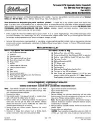
Firing Order: 1-8-4-3-6-5-7-2<br />
Figure 1 - 283-400 c.i.d Chevrolet V8<br />
Firing Order and Timing Marks<br />
Turn distributor counter clockwise to advance timing<br />
Part #<strong>2201</strong>, <strong>2204</strong>, <strong>2205</strong>, <strong>2207</strong>, <strong>2208</strong>, <strong>2209</strong> & <strong>2210</strong><br />
Rev. 9/26/12 - QT/mc<br />
Page 4 of 4<br />
advance port on your carburetor, we suggest the following procedure.<br />
Before removing the vacuum line from your carburetor, with the engine<br />
idling, pull the hose off the port that routes to the vacuum advance<br />
canister. After the hose has been removed from the carb, place your<br />
finger over the vacuum outlet. If (at idle), you feel your finger being<br />
sucked in toward the carburetor, you have full-time vacuum advance. If<br />
you do not feel any vacuum pulling at your finger with the engine at an<br />
idle, you have timed/ported vacuum advance.<br />
TUBULAR EXHAUST SYSTEM:<br />
For best performance, a tubular exhaust system is recommended with<br />
the Performer package to provide the most low-end torque. Please<br />
consult your <strong>Edelbrock</strong> dealer or the <strong>Edelbrock</strong> catalog for a listing of<br />
available <strong>Edelbrock</strong> Tubular Exhaust Systems.<br />
Timing<br />
Marks<br />
Figure 2 - Timing Chain Sprocket Alignment<br />
<strong>Edelbrock</strong> LLC • 2700 California St. • Torrance, CA 90503<br />
Tech-Line: 1-800-416-8628<br />
®<br />
©2012 <strong>Edelbrock</strong> LLC<br />
Brochure #63-0154