Installation Instruction - Edelbrock
Installation Instruction - Edelbrock
Installation Instruction - Edelbrock

Create successful ePaper yourself
Turn your PDF publications into a flip-book with our unique Google optimized e-Paper software.
®<br />
Part #1403, 1404, 1405, 1406, 1407, 1409, 1410, 1411, 1412 & 1413<br />
Rev. 5/29/13- QT/mc Page 1<br />
EDELBROCK PERFORMER SERIES CARBURETORS<br />
Part #1403, 1404, 1405, 1406, 1407, 1409, 1410, 1411, 1412 & 1413<br />
INSTALLATION INSTRUCTIONS<br />
PLEASE study these instructions carefully before beginning this installation. Most installations can be accomplished with common tools and<br />
procedures. However, you should be familiar with and comfortable working on your vehicle. If you do not feel comfortable performing this installation,<br />
it is recommended to have the installation completed by a qualified mechanic. If you have any questions, please call our Technical Hotline at:<br />
1-800-416-8628, 7:00 am - 5:00 pm, Pacific Standard Time, Monday through Friday.<br />
IMPORTANT NOTE: Proper installation is the responsibility of the installer. Improper installation<br />
will void your warranty and may result in poor performance and engine or vehicle damage.<br />
DESCRIPTION: <strong>Edelbrock</strong> Performer Series Carburetors have been calibrated, factory flow-tested, and preset. These instructions also apply to<br />
carburetors featuring our EnduraShine finish. Please read all instructions prior to installation. These are non-emissions carburetors, check your<br />
local emissions laws.<br />
ATTENTION: EDELBROCK CARBURETORS ARE NOT CALIBRATED FOR OR COMPATIBLE WITH ALCOHOL RACE FUEL OR E85 PUMP FUEL.<br />
USE OF ALCOHOL OR E85 IN YOUR EDELBROCK CARBURETOR WILL DAMAGE YOUR CARBURETOR AND VOID YOUR WARRANTY. THESE<br />
FUELS CAN ALSO DAMAGE OTHER FUEL SYSTEM COMPONENTS, UNLESS SPECIFICALLY DESIGNED FOR USE WITH ALCOHOL FUELS.<br />
NOTE: <strong>Edelbrock</strong> Performer Series carburetors are not for computer-controlled applications. That includes some 1981 & later GM<br />
vehicles with Q-Jet carburetor and some 1981 & later Ford vehicles with automatic overdrive (AOD) transmissions.<br />
KIT CONTENTS:<br />
q 1 <strong>Installation</strong> <strong>Instruction</strong> Sheet<br />
q 1 Warranty Card<br />
q 1 Square-Bore Base Gasket<br />
q 1 Air Horn Gasket<br />
q 1 Air Cleaner Stud<br />
q 1 Red Choke Positive Wire (Electric choke carburetors only)<br />
q 1 Black Choke Ground Wire (Electric choke carburetors only)<br />
q 2 5/32” Vacuum Caps (Except #1409 & 1410)<br />
q 1 5/32” Vacuum Tee (Except #1409 & 1410)<br />
q 1 1/4 NPT Pipe Plug (Except #1409 & 1410)<br />
q 1 Throttle Cable Ball-End Stud - 10-32 x .250”<br />
(Except #1409 & 1410)<br />
q 1 10-32 Hex Nut (Except #1409 & 1410)<br />
q 1 3/16” Internal Star Washer (Except #1409 & 1410)<br />
q 4 5/16” SAE Flat Washers (EnduraShine finish only)<br />
q 1 In-line Fuel Filter Kit (#1405 and #1406 Only)<br />
CHECK THE FOLLOWING BEFORE BEGINNING INSTALLATION<br />
WARNING: WHEN WORKING AROUND GASOLINE, ALWAYS WORK IN A WELL VENTILATED AREA AND KEEP ALL OPEN FLAMES, SPARKS, AND<br />
OTHER SOURCES OF IGNITION AWAY FROM THE WORK AREA. FAILURE TO DO SO CAN RESULT IN A FIRE OR EXPLOSION.<br />
q Replace or add an in-line fuel filter. Dirt (i.e. corrosion residue or<br />
other debris) found in carburetor will void your warranty.<br />
q Check and replace the air filter if necessary.<br />
q Check PCV valve and replace if clogged.<br />
q Check all hoses for leaks or cracks and replace if necessary.<br />
q New fuel filter (<strong>Edelbrock</strong> #8135 or equivalent)<br />
q Chrome Steel Fuel Line Kit #8134 includes fuel filter.<br />
q Banjo Fuel Fitting #8089 (if required for air cleaner clearance).<br />
q New air cleaner (<strong>Edelbrock</strong> #1221 or #4221 recommended). If<br />
stock or other air cleaner is to be used, check fit on carburetor<br />
before installation to determine if <strong>Edelbrock</strong> Air Cleaner Spacer<br />
#8092 is required.<br />
q Choke cable kit (manual choke only) or electrical connectors<br />
(electric choke only).<br />
q Throttle, transmission, and cruise control bracket #8031, 8036,<br />
or 8030 (chrome) for 1972-1978 small-block Chevrolet. Other<br />
applications may require modification to original bracket.<br />
q Divided Square-Bore Heat Insulator Gasket #9266 for dual-plane<br />
(stock or Performer series) manifolds. May be used in place of<br />
Square-Bore Adapter Plate #2732 on some <strong>Edelbrock</strong> manifolds.<br />
PARTS AND TOOLS RECOMMENDED FOR INSTALLATION<br />
q Check fuel pump for proper operation. Replace if necessary.<br />
q Check the intake manifold and cylinder head gaskets for leaks and<br />
replace if necessary.<br />
q Check the ignition system: clean and gap or replace spark plugs,<br />
plug wires, and adjust ignition timing to proper specifications.<br />
q Throttle Linkage Kits for Ford or Chrysler applications (See<br />
Carburetor PREPARATION, Step #1)<br />
q Carburetor adapter, if carburetor is to be installed on other then<br />
square-bore intake manifold. See steps #4 and #5 for specific part<br />
numbers. Do not use a 4-bbl to 2-bbl adapter (Use <strong>Edelbrock</strong> carbs<br />
on intake manifolds designed for 4-bbl carburetors only!)<br />
q Universal Throttle Return Spring Kit #8005 (if original return spring<br />
cannot be reused).<br />
q Sockets/wrenches/tubing wrenches<br />
q Pliers<br />
q Hacksaw and/or tubing cutter<br />
q Screwdrivers & Torx driver (for electric choke models)<br />
q Wire crimpers (for electric choke models)<br />
q Test Meter or Test Light (for electric choke models)<br />
©2013 <strong>Edelbrock</strong> LLC<br />
Brochure #63-0061
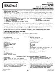
FUEL INLET for 3/8” hose (Except marine<br />
models #1409 & #1410 which use a 3/8”<br />
inverted flare fitting)<br />
MARINE FUEL PUMP VENT<br />
(Not shown. #1409 & #1410 ONLY)<br />
CANISTER VAPOR VENT<br />
(#1400 Only)<br />
PART NUMBER STAMPING<br />
(Except EnduraShine Models)<br />
3/16” TIMED VACUUM<br />
(Distributor vacuum advance port<br />
for emissions controlled engines)<br />
BEFORE REMOVING OLD CARBURETOR<br />
1. Determine if the distributor vacuum port is timed (no vacuum<br />
at idle) or full (vacuum present at idle). With the engine at<br />
operating temperature and idling, pull the vacuum advance hose<br />
off of the carburetor and “feel” for vacuum by putting your finger<br />
on the vacuum port (See Fig. 2). If<br />
Fig. 2<br />
your distributor has timed vacuum<br />
advance, you will hook the vacuum<br />
hose from the distributor to the<br />
passenger side vacuum port on<br />
the new carburetor. If it has full<br />
vacuum advance, it will be hooked<br />
up to the driver side port.<br />
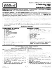
2. The stock steel fuel line must be modified to accommodate a<br />
rubber fuel hose as the stock steel line will not connect directly to<br />
the Performer Series Carburetor. The use of the <strong>Edelbrock</strong> Universal<br />
Fuel Line Kit #8135 is highly recommended. #8135 contains a fuel<br />
filter, rubber fuel hose, and fittings to adapt to 5/16” or 3/8” stock<br />
steel fuel lines (See Fig. 3). NOTE: #1405 and #1406 carburetors<br />
are supplied with a fuel filter. If using #8135 on these carburetors,<br />
the filter included in #8135 can be saved for later use.<br />
WARNING: DO NOT slide the rubber fuel hose directly onto the steel<br />
fuel line, proper fuel fittings must be used to avoid fuel leaks. Be<br />
sure to deburr and clean the stock steel fuel line after modification.<br />
Cut Stock Fuel Line and Install<br />
fittings from Kit #8135<br />
Hose To Carburetor<br />
Fuel Filter<br />
OEM Steel Fuel Line<br />
Fig. 3 - Fuel Line Kit #8135 Installed on Stock Steel Line<br />
Part #1403, 1404, 1405, 1406, 1407, 1409, 1410, 1411, 1412 & 1413<br />
Rev. 5/29/13- QT/mc Page 2<br />
IDLE MIXTURE SCREWS<br />
Left screw for left side of carb<br />
Right screw for right side of carb<br />
PCV PORT<br />
(For 3/8” Hose)<br />
NOT FOR FUEL!<br />
Figure 1 - Fittings and Vacuum Port Locations<br />
INSTALLATION PROCEDURE<br />
POWER BRAKE PORT<br />
(Except Marine Models)<br />
Rear Lower Side, 1/4 NPT<br />
IF NOT IN USE, MUST BE<br />
PLUGGED WITH 1/4 NPT<br />
PIPE PLUG (SUPPLIED)<br />
IDLE SPEED<br />
SCREW<br />
3/16” MANIFOLD VACUUM<br />
(Distributor vacuum advance port for<br />
non-emissions controlled engines)<br />
3. WARNING: The use of a new fuel filter (included with #1405 and<br />
#1406) between the fuel pump and carburetor is required. Failure<br />
to do so will void the manufacture’s warranty of the carburetor.<br />
4. You must use <strong>Edelbrock</strong> Adapter #2696 or Adapter & Fuel<br />
Line Kit #2697 when installing a Performer Series carburetor on a<br />
General Motors Quadrajet or Chrysler Thermoquad intake manifold.<br />
#2697 includes adapter #2696 and fuel line kit #8135. Do not use<br />
an open adapter (See Fig. 4).<br />
Fig. 4<br />
5. You must use <strong>Edelbrock</strong> Adapter #2732 when installing a<br />
Performer Series carburetor on certain <strong>Edelbrock</strong> intake manifolds.<br />
In those applications, install the adapter as shown (See Fig. 5).<br />
Square-Bore Adapter<br />
Plate #2732<br />
Gasket<br />
Manifold<br />
Fig. 5<br />
©2013 <strong>Edelbrock</strong> LLC<br />
Brochure #63-0061
6. Do not use more than 6.5 PSI fuel pressure. Excessive fuel<br />
pressure may cause flooding. If your fuel pressure is too high,<br />
install an adjustable pressure regulator, such as <strong>Edelbrock</strong> #8190.<br />
7. It may be necessary to re-route the fuel line to prevent interference<br />
with the air cleaner. Test fit your air cleaner on your new carburetor<br />
before you begin installation. Look for areas of interference such as<br />
the choke housing, fuel inlet fitting, and fuel line.<br />
PERFORMER SERIES CARBURETOR INSPECTION<br />
1. Check for possible damage to the carburetor.<br />
2. Make sure all throttle linkages operate freely.<br />
3. Ensure that all fuel inlet and vacuum ports are free from packing<br />
material.<br />
CARBURETOR REMOVAL<br />
1. Prior to removal, make sure that the engine is cool.<br />
2. Disconnect the negative battery cable from the battery.<br />
3. Remove air cleaner. Be sure to carefully disconnect any hoses from<br />
the air cleaner and note their location for reinstallation. You may<br />
want to mark them with masking tape for easy reference.<br />
4. Disconnect throttle linkage, kickdown linkage (certain automatic<br />
transmission applications only), cruise control (if equipped) and any<br />
return springs if present.<br />
NOTE: Check carefully for the precise location of all these linkages<br />
and return springs. You may want to mark them with masking tape<br />
for easy reference.<br />
5. Disconnect all wires, tubes, and hoses from carburetor and note<br />
their locations.<br />
NOTE: There should be a maximum of one wire to the electric<br />
choke and one to the idle compensator solenoid (if equipped<br />
with A/C). Any other electrical wiring attached to your carburetor<br />
indicates a computer controlled engine. <strong>Edelbrock</strong> carburetors will<br />
not function correctly on computer controlled applications.<br />
6. Disconnect the heater tube from the choke housing (if so equipped).<br />
<strong>Edelbrock</strong> carburetors do not use the hot-air-style choke, so this<br />
tube may be left disconnected with no problems. If you would like to<br />
cover this opening on a stock manifold, you may be able to use the<br />
appropriate <strong>Edelbrock</strong> Choke Adapter Plate: #8901 for small-block<br />
Chevrolets; #8961 for big-block Chevrolets; #8951 for Oldsmobile<br />
V8s; #8971 for 351-M/400 Fords; #8981 for 351-W Fords.<br />
7. Carefully remove the fuel line from the carburetor. TAKE EXTREME<br />
CARE NOT TO SPILL ANY EXCESS FUEL. Place a rag underneath<br />
the fuel line to absorb any spillage that may occur. Certain models<br />
require two wrenches to remove the fuel line; one to hold the fitting<br />
on the carburetor and the second to turn the fitting on the fuel line.<br />
Use a tubing wrench to avoid rounding the tube fitting nut.<br />
8. Remove mounting nuts or bolts and washers. Be sure to put them<br />
where they won’t fall into the intake manifold upon carburetor<br />
removal.<br />
Part #1403, 1404, 1405, 1406, 1407, 1409, 1410, 1411, 1412 & 1413<br />
Rev. 5/29/13- QT/mc Page 3<br />
9. Remove carburetor, being careful not to spill any dirt into the intake<br />
manifold. Immediately place a clean rag into the intake manifold to<br />
keep foreign objects out.<br />
10. Remove old mounting gasket and thoroughly clean mounting<br />
surface. Compare old carb gasket to the gasket included with your<br />
<strong>Edelbrock</strong> carburetor. If there is a difference in bolt pattern or bore<br />
spacing, an adapter will be required (see “Before Removing Old<br />
Carburetor”, steps #4 & #5).<br />
1. Compare the throttle arm<br />
of your new carburetor<br />
with the old one to be<br />
sure that all required<br />
linkages will hook up.<br />
Install the proper throttle<br />
and transmission linkage<br />
for your particular<br />
application. Throttle stud<br />
is removable and must<br />
be installed in the proper<br />
CARBURETOR PREPARATION<br />
location. Chrysler vehicles with automatic transmission will require<br />
Throttle Lever Kit #1481. Ford vehicles with automatic transmission<br />
and cable linkage will require Throttle Lever Kit #1483 (See Fig. 6)<br />
and Throttle Cable Plate Kit #1490 (for 289-302), #1491 (for 351-<br />
W), #1493 (for 351-C & 351-M/400), or #1495 (for 429/460).<br />
2. Check and prepare carburetor for proper vacuum fitting installation<br />
(EGR, power brakes, PCV, distributor, transmission, etc.), using the<br />
supplied vacuum caps, “T” and hose when applicable. If vacuum<br />
port at rear of carb is not used, plug with the 1/4 NPT pipe plug<br />
supplied (Except marine models, port is not drilled).<br />
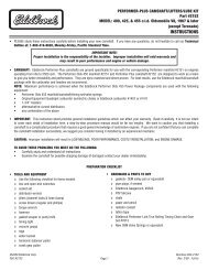
3. On electric choke models (See Fig. 7), remove one choke housing<br />
retaining screw and install eyelet end of choke ground wire (black)<br />
to the choke housing, and reinstall the screw. Connect clip end of<br />
choke ground wire to negative (–) spade terminal on choke housing.<br />
Black wire (–): To Ground<br />
(Carb Body)<br />
Red Wire (+): To Ignition Key Activated<br />
12V Source (NOT coil or alternator!)<br />
Ford Throttle Lever #1483<br />
bolts to carb throttle arm<br />
CARBURETOR INSTALLATION<br />
1. Remove rag from intake manifold and install new studs, mounting<br />
gasket and adapters (where applicable).<br />
NOTE: Do not use any cement, glue, or RTV sealant on gasket.<br />
2. Carefully place new carburetor on gasket.<br />
Fig. 6<br />
Retaining<br />
Screws (3)<br />
Fig. 7<br />
©2013 <strong>Edelbrock</strong> LLC<br />
Brochure #63-0061
3. Replace all mounting nuts and washers. EnduraShine finish<br />
carburetors should use the supplied 5/16” flat washers under any<br />
other washers used. Hand tighten with a short box-end wrench,<br />
alternating between diagonally opposed nuts.<br />
CAUTION: Overtightening may break carb base and void your<br />
warranty.<br />
4. Connect all throttle and<br />
transmission linkages and<br />
throttle return springs. You may<br />
have to cut, bend or modify your<br />
stock throttle cable brackets<br />
to fit the new carburetor, or<br />
use GM #352279 (See Fig. 8).<br />
1972-78 small-block Chevrolets<br />
may use <strong>Edelbrock</strong> Throttle, Transmission, and Cruise Control<br />
bracket #8031, #8036, or #8030 (chrome).<br />
IMPORTANT NOTE: With engine OFF, make sure that there is<br />
no interference when opening and closing the throttle. Be sure<br />
there is no binding or hanging up between idle and wide open<br />
throttle, as this could cause the throttle to stick open, resulting<br />
in loss of engine speed control.<br />
5. Manual choke:<br />
Connect manual<br />
choke cable to<br />
the choke lever<br />
cable mounting<br />
bracket (See Fig.<br />
9). Electric choke:<br />
Connect the red<br />
choke wire to a 12<br />
GM<br />
#352279<br />
Manual Choke Cable and<br />
Fuel Line Connection<br />
Fig. 8<br />
Fig. 9<br />
volt positive (+) source that is activated by the ignition switch (Not<br />
the coil or alternator; see Fig. 7).<br />
NOTE: If manual choke is not connected (secondary carb of dualquad<br />
setup, for example) then the choke blade must be fixed open.<br />
To lock open, use a stiff piece of wire between the choke lever and<br />
the mounting bracket. Fold the wire to double its thickness about<br />
one inch from one end. Insert the wire in the choke lever, hold<br />
choke blade in the wide-open position, and tighten the cable clamp<br />
on the folded end of the wire.<br />
6. Connect all vacuum hoses to their proper location on the carburetor<br />
(See Fig. 1). Replace hoses that appear brittle or cracked to prevent<br />
vacuum leaks.<br />
7. Connect fuel line to carburetor. Avoid contact with any sharp edges<br />
or areas of extreme heat.<br />
NOTE: Some late model Ford 460 engines are equipped with hot<br />
fuel bypass units. It is necessary to replace the stock unit with Ford<br />
#E3TZ9N176B (with blue dot) which has a .040” orifice.<br />
Part #1403, 1404, 1405, 1406, 1407, 1409, 1410, 1411, 1412 & 1413<br />
Rev. 5/29/13- QT/mc Page 4<br />
8. <strong>Edelbrock</strong> idle compensator #8059 may be installed to raise idle<br />
speed during air conditioning compressor operation.<br />
9. Install new air horn gasket and air cleaner stud (supplied). Install air<br />
cleaner, making sure it does not contact the carburetor linkage or<br />
fuel line, and has proper hood clearance. We recommend <strong>Edelbrock</strong><br />
Pro-Flo chrome air cleaner #1221, which is a 14” diameter, open<br />
element air cleaner that is designed to fit all <strong>Edelbrock</strong> Performer<br />
Series carburetors. Extremely<br />
low profile air cleaners will not<br />
fit electric choke carburetors<br />
without air cleaner spacer<br />
#8092 (due to choke and fuel<br />
line interference) but will fit<br />
manual choke carburetors when<br />
used with 90° banjo fuel inlet<br />
fitting #8089 (See Fig. 10).<br />
10. Mark air cleaner stud for<br />
proper length, remove from<br />
carburetor, and cut with a<br />
hacksaw. Deburr stud and<br />
reinstall it in the carburetor,<br />
along with the air cleaner<br />
(See Fig. 11).<br />
11. Recheck all linkage for<br />
smooth throttle operation.<br />
12. Reconnect the negative battery cable from the battery.<br />
13. Start engine and check for fuel or vacuum leaks. With engine at<br />
normal operating temperature and the choke fully open, set idle<br />
speed and mixture screws (See Carburetor Owner’s Manual).<br />
CAUTION: Be alert to carburetor flooding. Flooding can be caused<br />
by dirt, small particles of hose cuttings, floats and inlet needles<br />
which have settled during shipping, etc. When the fuel pump is<br />
turned on or when the engine is first started, watch closely for signs<br />
of flooding. If flooding occurs, turn engine off immediately and<br />
lightly tap on the side of the carburetor that is flooding, in the rear<br />
needle and seat area with a rawhide mallet, or wooden handle of a<br />
hammer. Start engine and see if flooding continues.<br />
WARNING: Never pour fuel directly down the carburetor when<br />
attempting to start the engine! This may cause a backfire and<br />
possible engine compartment fire, resulting in engine or vehicle<br />
damage, personal injury, and/or death.<br />
14. When restarting the vehicle, after it has been sitting for 10-30<br />
minutes, you may experience some difficulty starting. The result<br />
will be similar to a flooded carburetor. To help eliminate or<br />
minimize this issue, the use of an <strong>Edelbrock</strong> Heat Insulator Gasket<br />
Part Number 9266 (sold separately) is highly recommended. For<br />
additional heat insulator selections please visit www.edelbrock.<br />
com.<br />
<strong>Edelbrock</strong> LLC • 2700 California St. • Torrance, CA 90503<br />
Tech-Line: 1-800-416-8628 • Office Line: 310-781-2222<br />
Banjo Fitting<br />
#8089<br />
Fig. 10<br />
Fig. 11<br />
©2013 <strong>Edelbrock</strong> LLC<br />
Brochure #63-0061
®<br />
Partes #1403, 1404, 1405, 1406, 1407, 1409, 1410, 1411, 1412 & 1413<br />
Rev. 5/29/13- QT/mc Página 5<br />
CARBURADORES EDELBROCK SERIE PERFORMER<br />
Partes #1403, 1404, 1405, 1406, 1407,<br />
1409, 1410, 1411, 1412 y 1413<br />
INSTRUCCIONES DE INSTALACIÓN<br />
POR FAVOR lea estas instrucciones cuidadosamente antes de empezar la instalación. La mayoría de instalaciones se pueden lograr con herramientas<br />
comunes y procedimientos simples. Sin embargo, usted debe estar familiarizado y cómodo trabajando en su vehículo. Si usted no se siente cómodo<br />
de realizar esta instalación, se recomienda que la instalación sea hecha por un mecánico calificado. Si usted tiene alguna duda o problema, por favor<br />
llame a nuestra Línea de Asistencia Técnica: 1-800-416-8628 (Teléfono y servicio válidos sólo en E.U.A.), 7:00 am – 5:00 pm, Horario Estándar<br />
del Pacífico, Lunes a Viernes.<br />
NOTA IMPORTANTE: La instalación adecuada es responsabilidad del instalador. La instalación incorrecta anulará<br />
su garantía (No válida en México) y puede resultar en un rendimiento inferior y dañar el motor o el vehículo.<br />
DESCRIPCIÓN: Los Carburadores <strong>Edelbrock</strong> Serie Performer han sido calibrados, probados del flujo y preestablecido en la en fábrica. Estas<br />
instrucciones también le aplican a los carburadores que ofrecen nuestro acabado EnduraShine. Por favor lea todas las instrucciones antes de la<br />
instalación. Estos son carburadores sin emisiones, revise sus leyes de emisiones locales.<br />
ATENCIÓN: LOS CARbURADORES EDELbROCK NO ESTáN CALIbRADOS PARA, O SON COMPATIbLES CON EL COMbUSTIbLE DE CARRERAS A<br />
bASE DE ALCOhOL O COMbUSTIbLE E85. EL USO DE ALCOhOL O E85 EN SU CARbURADOR EDELbROCK DAñARá SU CARbURADOR. ESTOS<br />
COMbUSTIbLES TAMbIéN PUEDEN DAñAR A OTROS COMPONENTES DEL SISTEMA DE COMbUSTIbLE, SALVO qUE éSTE DISEñADO PARA USO<br />
EN COMbUSTIbLES DE ALCOhOL.<br />
NOTA: Los Carburadores <strong>Edelbrock</strong> Serie Performer no son para aplicaciones controladas por computadora. Eso incluye algunos 1981 y vehículos<br />
GM de años más tarde con del carburador Q-Jet y algunos 1981 y los vehículos de Ford posteriores con transmisiones de sobremarcha (AOD).<br />
q 1 Hoja de Instrucciones de Instalación<br />
q 1 Tarjeta de Garantía (E.U.A.) No Válida en México<br />
q 1 Junta Cuadrada para Base<br />
q 1 Junta para Claxon de Aire<br />
q 1 Poste para Filtro de Aire<br />
q 1 Cable Rojo Positivo del Estrangulador<br />
(Carburadores con estrangulador eléctrico solamente)<br />
q 1 Cable Negro a Tierra del Estrangulador<br />
(Carburadores con estrangulador eléctrico solamente)<br />
IMPORTADO POR:<br />
ZONE COMPRA, S. DE R.L. DE C.V.<br />
AV. GUERRERO No. 2911-B<br />
COL. GUERRERO<br />
NUEVO LAREDO, TAMAULIPAS. MÉXICO<br />
C.P. 88240 R.F.C. ZCO-980914-I98<br />
Tel: (867) 719-2683<br />
EL JUEGO INCLUYE:<br />
q 2 Tapas de Vacío de 4 mm (5/32”) (Excepto #1409 y #1410)<br />
q 1 Te de Vacío de 4 mm (5/32 ”) (Exc epto #1409 y #1410)<br />
q 1 Tapón de Tub o 6,35 mm (¼ ”) NPT (Excepto #1409 y #1410)<br />
q 1 Soporte de Cable de Regulador con Extremo de Bola de<br />
7,8 mm x 6,35 mm (10/32” x .250”) (Excepto #1409 y #1410)<br />
q 1 Tuerca de 7,8mm (10-32) (Ex cepto #1409 y #1410)<br />
q 1 Arandela de Estrella Interna de 4,8 mm (Excepto #1409 y #1410)<br />
q 4 Arandelas Planas SAE 7,9 mm (Solamente con acabado<br />
EnduraShine<br />
REVISE LO SIGUIENTE ANTES DE EMPEZAR LA INSTALACIÓN<br />
ADVERTENCIA: CUANDO TRAbAjE CERCA DE gASOLINA, SIEMPRE TRAbAjE EN UN áREA bIEN VENTILADA Y MANTENgA TODAS LAS LLAMAS AbIERTAS,<br />
ChISPAS Y OTRAS FUENTES DE IgNICIóN LEjOS DEL áREA DE TRAbAjO. NO hACERLO PUEDE RESULTAR EN UN INCENDIO O EXPLOSIóN.<br />
q Reemplace el filtro de combustible. La suciedad (es decir, residuos de<br />
corrosión u otros desechos) pueden causar daños.<br />
q Revise y reemplace el filtro de aire si es necesario<br />
q Compruebe la válvula de PCV y reemplace si está obstruida.<br />
q Revise todas las mangueras para detectar fugas o grietas y reemplazar<br />
si es necesario.<br />
q Nuevo filtro de combustible (<strong>Edelbrock</strong> # 8135 o equivalente) Juego<br />
de línea y filtro de combustible cromado # 8134 incluye el filtro de<br />
combustible.<br />
q Adaptador de montaje de combustible #8089 (si se necesita para el<br />
espacio del filtro de aire).<br />
q Filtro de aire nuevo (<strong>Edelbrock</strong> recomienda # 1221 o # 4221). Si usa<br />
el recomendado u otro filtro de aire, revise que quepa en el carburador<br />
antes de su instalación para determinar si el espaciador del filtro de<br />
aire <strong>Edelbrock</strong> # 8092 es necesario.<br />
q Juego del cable del estrangulador (solamente en estrangulador manual)<br />
o conectores eléctricos (estrangulador eléctrico solamente).<br />
q Soporte de acelerador, transmisión y soporte de control de crucero #<br />
8031, 8036, u 8030 cromado) para Chevrolet 1972-1978 de bloque<br />
pequeño. Otras aplicaciones pueden requerir una modificación en el<br />
soporte original.<br />
q Junta Aislante de Calor de Abertura Cuadrada Dividida # 9266 para<br />
colectores de doble plano (de Inventario o Serie Performer). Puede<br />
utilizarse en lugar de la Placa Adaptadora<br />
q Abertura Cuadrada Dividida # 2732 en algunos colectores de <strong>Edelbrock</strong>.<br />
PIEZAS Y HERRAMIENTAS RECOMENDADAS PARA LA INSTALACIÓN<br />
q Revise la bomba de combustible para un correcto funcionamiento.<br />
Reemplace si es necesario.<br />
q Revise el colector de admisión y las juntas de culata en busca de fugas<br />
y sustituya si es necesario.<br />
q Revise el sistema de encendido: limpie y vacíe o reemplace las<br />
bujías, cables de las bujías y ajuste el tiempo de encendido según las<br />
especifícaciones.<br />
q Juegos de vinculación del acelerador para aplicaciones de Ford o<br />
Chrysler (Ver Preparación del carburador, el paso # 1)<br />
q Adaptador de carburador, si el carburador es para ser instalado en otros<br />
colectores de admisión cuadrados. Consulte los pasos # 4 y # 5 del<br />
número de parte específica. No utilice un adaptador de 4-2-bbl (¡Utilice<br />
los carburadores <strong>Edelbrock</strong> en los colectores de admisión diseñados<br />
para carburadores de 4 barriles solamente!)<br />
q Juego de Resorte para Acelerador Universal # 8005 (si el resorte<br />
original no puede ser reutilizado).<br />
q Dados / llaves inglesas / llaves de tubo<br />
q Pinzas<br />
q Sierra y/o cortador de tubos<br />
q Destornilladores y Mandos Torx (para los modelos de estranguladores<br />
eléctricos)<br />
q Plegadores de cable (para los modelos de estranguladores eléctricos)<br />
q Prueba de medidor o luz de prueba (para los modelos de<br />
estranguladores eléctricos)<br />
©2013 <strong>Edelbrock</strong> LLC<br />
Brochure #63-0061
ENTRADA DE COMbUSTIbLE<br />
para manguera de 9,5 mm (excepto modelos<br />
marinos #1409 y #1410 el cual<br />
usa 9,5 de adaptador<br />
de abocinado invertido)<br />
VENTILACIóN DE VAPOR<br />
DEL ARMAZóN<br />
(#1400 Solamente)<br />
Antes de retirAr el cArburAdor viejo<br />
1. Determine si el puerto de vacío del distribuidor está programado<br />
(sin vacío en marcha lenta) o total (vacío presente en marcha<br />
lenta). Con el motor a la temperatura de funcionamiento e<br />
inactividad, tire de la manguera de avance de vacío del carburador<br />
y “sienta” el vacío poniendo sus<br />
dedos en el puerto de vacío (Ver fig.<br />
Fig. 2<br />
2). Si su distribuidor tiene vacio de<br />
programación avanzada, usted debe<br />
de enganchar la manguera de vacío del<br />
distribuidor al puerto de vacío del lado<br />
del pasajero en el carburador nuevo.<br />
Si tiene vacío avanzado completo, será<br />
conectado al puerto del distribuidor<br />
del lado del conductor.<br />
2. La línea de combustible original de acero debe ser modificado para<br />
acomodar una manguera de caucho resistente al combustible como<br />
la línea original no se conectará directamente a carburadores de la<br />
seria Performer. Es muy recomendable que utilice el kit de línea de<br />
combustible universal # 8135 de la marca <strong>Edelbrock</strong>. El kit #8135<br />
contiene un filtro, manguera de neopreno resistente al combustible y<br />
adaptadores para líneas originales de combustible de 7,9 mm (5/16”)<br />
o 9,5 mm (3/8”) (Ver Fig. 3). NOTA: carburadores # 1405 y # 1406<br />
se suministran con un filtro de combustible. Si se utiliza # 8135 en<br />
estos carburadores, el filtro incluido en el # 8135 se pueden guardar<br />
para su uso posterior<br />
Corte la línea de combustible<br />
y añada el adaptador #8135<br />
Manguera de neopreno<br />
al carburador<br />
VENTILACIóN DE LA bOMbA<br />
DE COMbUSTIbLE MARINA<br />
(No se muestra. #1409 y #1410 Solamente)<br />
SELLO DEL NÚMERO DE PARTE<br />
(Excepto en los modelos<br />
EnduraShine) VACÍO PROgRAMADO 4,8 mm<br />
(Puerto avanzado del vacío de distribuidor<br />
para las emisiones controladas del motor)<br />
Filtro de<br />
combustible<br />
Línea combustible<br />
de acero<br />
Fig. 3 – Juego de Línea Combustible #8135 Instalado en la Línea de Acero de Fábrica<br />
ADVERTENCIA: NO deslice la manguera de combustible de goma<br />
directamente sobre la línea de combustible de acero, uniones<br />
Partes #1403, 1404, 1405, 1406, 1407, 1409, 1410, 1411, 1412 & 1413<br />
Rev. 5/29/13- QT/mc Página 6<br />
TORNILLOS PARA LA MARChA LENTA<br />
Tornillo izquierdo para el izquierdo del<br />
carburador<br />
Tornillo derecho para el lado derecho del<br />
carburador<br />
PUERTO PCV<br />
(Para Manguera de 9,5 mm)<br />
¡NO PARA COMbUSTIbLE!<br />
Figura 1 – Ubicaciones de Adaptadores y Puerto de Vacío<br />
INSTRUCCIONES DE INSTALACIÓN<br />
PUERTO DEL FRENOS DE PODER<br />
(Excepto los modelos marinos)<br />
Parte trasera inferior, 6,4 mm NPT<br />
SI NO SE USA, DEbE DE SER<br />
ENChUFADO CON UN TAPóN DE<br />
TUbO DE 6,4 mm (PROPORCIONADO)<br />
TORNILLO PARA VELOCIDAD EN<br />
MARChA LENTA<br />
VACÍO DEL MÚLTIPLE DE 4,8 mm<br />
(Puerto avanzado del vacío del<br />
distribuidor para las emisiones no<br />
controladas de los motores)<br />
apropiados del combustible se debe utilizar para evitar fugas de<br />
combustible. Asegúrese de desbarbar y limpiar la línea de combustible<br />
de acero original después de la modificación.<br />
3. ADVERTENCIA: El uso de un filtro de combustible nuevo (incluido<br />
con carburadores # 1405 y # 1406) entre la bomba de combustible y<br />
el carburador se requiere. De lo contrario, se anulará la garantía del<br />
fabricante del carburador.<br />
4. Usted debe de usar el Adaptador <strong>Edelbrock</strong> #2696 o Adaptador<br />
y juego de línea Combustible #2697 cuando instale un carburador<br />
de Serie Performer en un múltiple General Motors Quadrajet o<br />
Chrysler Thermoquad. El #2697 incluye un adaptador #2696 y juego<br />
de línea de combustible #8135.<br />
¡No use un adaptador abierto! (Ver Fig 4)<br />
Juego de Adaptador Quadrajet #2697 (¡No use un adaptador abierto!)<br />
Fig. 4<br />
5. Usted debe de usar el adaptador #2732 cuando instale un<br />
carburador Serie Performer en ciertos múltiples en esas aplicaciones,<br />
instale el adaptador como se muestra (Ver Fig. 5).<br />
Placa Adaptadora con Abertura<br />
Cuadrada #2732<br />
Junta<br />
Múltiple<br />
Fig. 5<br />
©2013 <strong>Edelbrock</strong> LLC<br />
Brochure #63-0061
6. No use más de 44,82 kPa (6.5 psi) de presión de combustible. El<br />
exceso de presión de combustible puede causar inundaciones. Si su<br />
presión de combustible es demasiado alta, instale un regulador de<br />
presión ajustable, como el de <strong>Edelbrock</strong> # 8190.<br />
7. Tal vez sea necesario enrutar la línea de combustible para evitar la<br />
interferencia con el filtro de aire. Pruebe el ajuste de su filtro de aire<br />
en el carburador nuevo antes de comenzar la instalación. Busque<br />
las áreas de interferencia, tales como la cubierta del estrangulador,<br />
conector de entrada de combustible y la línea de combustible.<br />
INSPECCIóN DEL CARbURADOR SERIE PERFORMER<br />
1. Verifique posibles daños en el carburador.<br />
2. Asegúrese de que todas las conexiones del acelerador operen<br />
ibremente.<br />
3. Asegúrese de que todos los puertos de entrada de combustible y de<br />
vacío estén libres de materiales de empaque.<br />
PARA REMOVER EL CARbURADOR<br />
1. Antes de removerlo, asegúrese de que el motor esté frío.<br />
2. Desconecte el cable negativo de la batería.<br />
3. Quite el filtro de aire. Asegúrese de desconectar cuidadosamente las<br />
mangueras del filtro de aire y tenga en cuenta su ubicación para su<br />
reinstalación. Usted puede marcarlas con cinta adhesiva para facilitar<br />
su referencia<br />
4. Desconecte el cable del estrangulador, la conexión (ciertas<br />
aplicaciones de transmisión automática), control de crucero (si lo<br />
tiene) y todos los resortes de retorno, si los hay.<br />
NOTA: Revise cuidadosamente la ubicación exacta de todas<br />
estas conexiones y los resortes de retorno. Si lo desea, los<br />
puede marcar con cinta adhesiva para facilitar su referencia.<br />
5. Desconecte todos los cables, tubos y mangueras del carburador y<br />
note sus ubicaciones.<br />
NOTA: Debe haber un máximo de un cable al estrangulador<br />
eléctrico y otro para el solenoide compensador de vacío (si está<br />
equipado con C.A). Cualquier otro cableado eléctrico conectado<br />
a su carburador indica un motor controlado por computadora.<br />
Los carburadores <strong>Edelbrock</strong> no funcionarán correctamente en las<br />
aplicaciones controladas por computadora.<br />
6. Desconecte el tubo de la resistencia de la carcasa del estrangulador<br />
(si lo tiene). Los carburadores <strong>Edelbrock</strong> no usan estrangulador<br />
de aire caliente, por lo que este tubo se puede desconectar de la<br />
izquierda sin problemas. Si desea cubrir esta apertura en un colector<br />
de valores, es posible que pueda usar la placa adaptadora adecuada<br />
<strong>Edelbrock</strong> Choke: # 8901 de Chevrolet smallblock; # 8961 de bloque<br />
grande Chevrolet; # 8951 de V8 Oldsmobile; # 8971 para 351 -M/400<br />
Ford; # 8981 de 351-W Ford.<br />
7. Retire con cuidado la línea de combustible del carburador. TENgA<br />
MUChO CUIDADO DE NO DERRAMAR EL EXCESO DE COMbUSTIbLE.<br />
Coloque un trapo debajo de la línea de combustible para absorber<br />
cualquier derrame que pueda ocurrir. Algunos modelos requieren<br />
dos llaves para remover la línea de combustible, uno para sujetar el<br />
conector en el carburador y el segundo para girar el conector en la<br />
línea de combustible. Utilice una llave de tubo para evitar el redondeo<br />
de la tuerca conectora del tubo.<br />
8. Retire las tuercas o tornillos de montaje y las arandelas. Asegúrese<br />
de colocarlos donde no se caigan en el colector de admisión después<br />
de retirar el carburador.<br />
Partes #1403, 1404, 1405, 1406, 1407, 1409, 1410, 1411, 1412 & 1413<br />
Rev. 5/29/13- QT/mc Página 7<br />
9. Quite el carburador, teniendo cuidado de no derramar suciedad en el<br />
colector de admisión. Inmediatamente coloque un trapo limpio en el<br />
colector de admisión para que no le caigan objetos extraños.<br />
10. Retire la junta vieja de montaje y limpie bien la superficie de montaje.<br />
Compare la junta vieja del carburador con la junta que se incluye con<br />
el carburador <strong>Edelbrock</strong>. Si hay una diferencia en el patrón de perno<br />
o espacio de la abertura, un adaptador va ser necesario (ver “antes<br />
de quitar el carburador viejo”, pasos # 4 y # 5).<br />
1. Compare el brazo del<br />
acelerador de su nuevo<br />
carburador con el viejo para<br />
asegurarse de que todas<br />
las conexiones necesarias<br />
se conecten. Instale el<br />
regulador adecuado y la<br />
conexión de transmisión<br />
para su aplicación en<br />
particular. El poste del<br />
acelerador es removible y<br />
se debe instalar en el lugar<br />
PREPARACIóN DEL CARbURADOR<br />
adecuado. Los vehículos Chrysler con transmisión automática<br />
requieren un Juego de palanca de acelerador # 1481. Los vehículos<br />
de Ford con transmisión automática y los conectores de cable<br />
requerirán un juego de palanca de acelerador # 1483 (Véase la Fig.<br />
6.) y el juego de placa de cable acelerador # 1490 (de 289 a 302), #<br />
1491 (de 351-W), # 1493 (de 351 - C & 351-M/400), o # 1495 (de<br />
429/460).<br />
2. Revise y prepare el carburador para la instalación correcta del<br />
adaptador de vacío (recirculación de los gases de escape “EGR”, frenos<br />
de potencia, ventilación positiva del cárter “PCV”, distribuidores,<br />
transmisión, etc), con los tapones de vacío suministrados, “T” y la<br />
manguera en su caso. Si el puerto de vacío en la parte posterior<br />
del carburador no se usa, tape el tubo de 6,4 mm NPT con el<br />
tapón proporconado (excepto los modelos marinos, el puerto no<br />
está perforado).<br />
3. En los modelos de los estranguladores eléctricos (Ver Fig. 7),<br />
remueva un tornillo retensor del caparazón e instale el extremo del<br />
ojal del cable de tierra del estrangulador (negro) a la cubierta del<br />
estrangulador y vuelva a instalar el tornillo. Conecte el gancho final<br />
del cable de tierra a la terminal negativa (-) del cable en la caparazón<br />
del estrangulador.<br />
Cable negro (-) a tierra<br />
(a cuerpo de carburador)<br />
La palanca del acelerador Ford<br />
#1483 se atornilla al brazo del<br />
acelerador del carburador<br />
Cable Rojo (+): A la llave de ignición activada<br />
Fuente con Tensión 12 V cc<br />
(NO bobina o alternador)<br />
Tornillo de<br />
retención (3)<br />
Fig. 7<br />
Fig. 6<br />
INSTALACIóN DEL CARbURADOR<br />
1. Retire el trapo del colector de admisión e instale nuevos postes, junta<br />
de montaje y adaptadores (si es aplicable).<br />
NOTA: No utilice ningún tipo de cemento, pegamento o sellador RTV<br />
en la junta.<br />
©2013 <strong>Edelbrock</strong> LLC<br />
Brochure #63-0061
2. Coloque con cuidado el nuevo carburador sobre la junta.<br />
3. Vuelva a colocar todos los tornillos y arandelas de montaje. Los<br />
carburadores con acabado EnduraShine deben de utilizar las<br />
arandelas planas de 7,9 mm (5/16”) proporcionadas. Apriete a mano<br />
con una llave de estrías, alternando entre las tuercas diagonalmente<br />
opuestas.<br />
PRECAUCIóN: Si aprieta demasiado puede romper la base del<br />
carburador.<br />
4. Conecte todos los conectores del<br />
acelerador y la transmisión y los<br />
resortes de retorno del acelerador.<br />
Puede que tenga que cortar,<br />
doblar o modificar sus soportes<br />
de cable del acelerador de fábrica<br />
para ajustarse al nuevo carburador<br />
o use GM # 352279 (Ver Fig.<br />
8). Chevrolet 1972-78 de bloque<br />
GM<br />
#352279<br />
Fig. 8<br />
pequeño puede utilizar acelerador <strong>Edelbrock</strong>, transmisión y control<br />
de crucero de la placa # 8031, # 8036 o # 8030 (cromo).<br />
NOTA IMPORTANTE: Con el motor APAGADO, asegúrese de que<br />
no haya interferencia al abrir y cerrar el acelerador. Cerciórese de<br />
que no se doble o se cuelgue entre la marcha lenta y el acelerado<br />
abierto, ya que esto podría causar que el acelerador se pegue en<br />
abierto, resultando en la pérdida de control de velocidad del motor.<br />
5. Estrangulación manual:<br />
Conecte el cable del<br />
Cable de Estrangulador Manual y<br />
Conexión a la Línea de Combustible<br />
estrangulador manual al<br />
cable de la palanca del<br />
estrangulador del soporte<br />
de montaje (véase la<br />
Fig. 9.). Estrangulación<br />
eléctrica: Conecte el cable<br />
rojo del estrangulador a<br />
una fuente positiva de 12<br />
Fig. 9<br />
V (+) que sea activada por<br />
el interruptor de ignición (Véase la Fig. 7).<br />
NOTA: Si el estrangulador manual no está conectado (carburador<br />
secundario de configuración doble, por ejemplo), entonces la hoja<br />
del estrangulador debe ser fijada libre. Para fijarlo abierto, use<br />
un trozo de alambre rígido entre la palanca del estrangulador y<br />
el soporte de montaje. Doble el alambre al doble de su espesor<br />
de 2,54 cm de un extremo. Inserte el alambre en la palanca del<br />
estrangulador, sostenga la hoja del estrangulador en una posición<br />
totalmente abierta y apriete la abrazadera del cable en el extremo<br />
doblado del alambre.<br />
6. Conecte todas las mangueras de vacío a su lugar apropiado en<br />
el carburador (ver fig. 1). Reemplace las mangueras que parecen<br />
frágiles o agrietadas para evitar fugas de vacío.<br />
7. Conecte la línea de combustible al carburador. Evite el contacto<br />
con los bordes afilados o las áreas de calor extremo. NOTA:<br />
Algunos modelos recientes de Ford 460 motores están equipados<br />
con unidades de derivación de combustible caliente. Es necesario<br />
sustituir la unidad original con Ford # E3TZ9N176B (con el punto azul)<br />
que tiene un orificio de 10,16 mm (.040”).<br />
8. El compensador de marcha lenta <strong>Edelbrock</strong> # 8059 puede ser<br />
Partes #1403, 1404, 1405, 1406, 1407, 1409, 1410, 1411, 1412 & 1413<br />
Rev. 5/29/13- QT/mc Página 8<br />
instalado para aumentar la velocidad de marcha lenta durante el<br />
funcionamiento del compresor de aire acondicionado.<br />
9. Instale una nueva junta de claxon de aire y filtro de aire (proporcionado).<br />
Instale el filtro de aire, asegurándose de que no haga contacto con la<br />
conexión del carburador o con la línea de combustible y tiene espacio<br />
correcto en el cofre. Le recomendamos el filtro de aire <strong>Edelbrock</strong><br />
Pro-Flo cromado # 1221, el cual es un filtro de aire libre de 35,56<br />
cm (14 “) de diámetro que está diseñado para adaptarse a todos<br />
los carburadores <strong>Edelbrock</strong> Series Performer. Los filtros de aire de<br />
extremo perfil bajo no ajustarán en<br />
lo carburadores con estranguladores<br />
eléctricos sin espacio para filtro de<br />
aire #8092 (debido a la interferencia<br />
entre las lineas de estrangulador<br />
y combustible) pero se ajustarán<br />
a carburadores de estrangulador<br />
manual cuando se use con la entrada<br />
de combustible de 90° Banjo #8089<br />
(Vea la Fig. 10).<br />
Ajustador Banjo<br />
#8089<br />
Fig. 10<br />
10. Marque el poste del filtro<br />
de aire para la longitud<br />
adecuada, retire el carburador<br />
y corte con una sierra para<br />
metales. Lime las rebabas<br />
del poste y vuelva a instalar<br />
en el carburador, junto con el<br />
filtro de aire (ver fig. 11).<br />
11. Vuelva a revisar todos<br />
las conexiones para el<br />
Fig. 11<br />
funcionamiento suave del<br />
acelerador.<br />
12. Vuelva a conectar el cable negativo de la batería.<br />
13. Arranque el motor y compruebe si hay fugas de combustible o<br />
vacío. Con el motor a temperatura normal de funcionamiento y el<br />
estrangulador abierto por completo, ajuste la velocidad de la marcha<br />
lenta y la mezcla de tornillos (vea el manual del carburador).<br />
PRECAUCIóN: Esté alerta a los ahogos del carburador. Los ahogos<br />
pueden ser causadas por la suciedad, pequeñas partículas de<br />
los cortes de mangueras, flotadores y agujas de entrada, que se<br />
han asentado durante el transporte, etc. Cuando la bomba de<br />
combustible se encienda o cuando el motor se prende por primera<br />
vez, vigile cualquier señal de ahogo. Si ocurre una ahogo, apague<br />
el motor inmediatamente y golpee ligeramente en el lado del<br />
carburador que está ahogado, en la aguja y el área del asiento<br />
trasero con un mazo de cuero crudo o el mango de madera de un<br />
martillo. Arranque el motor para ver si los ahogos continúan.<br />
ADVERTENCIA: ¡NUNCA VIERTA COMBUSTIBLE DIRECTAMENTE<br />
AL CARBURADOR AL INTENTAR PRENDER EL MOTOR! ESTO<br />
PUEDE CAUSAR UN FOGONAZO Y UN POSIBLE INCENDIO EN EL<br />
COMPARTIMIENTO DEL MOTOR, RESULTANDO EN DAÑOS AL<br />
MOTOR, AL VEHÍCULO, LESIONES PERSONALES Y / O LA MUERTE.<br />
14. Cuando se arranca el motor, después de haber corrido por 15 a 30<br />
minutos, se puede ser difícil para empezar. Los síntomas serán<br />
similares a un carburador inundado. Para eliminar o minimizar este<br />
problema, se recomienda el uso del <strong>Edelbrock</strong> empaque aislante<br />
contra calor #9266 (se vende por separado). Para ver las versiones<br />
adicionales de los empaques aislantes contra calor disponibles, visite<br />
www.edelbrock.com.<br />
<strong>Edelbrock</strong> LLC • 2700 California St. • Torrance, CA 90503<br />
Línea de Asistencia Técnica: 1-800-416-8628 Teléfono y Servicio Válido Sólo en E.U.A.<br />
©2013 <strong>Edelbrock</strong> LLC<br />
Brochure #63-0061