3530, 3531 - Pro-Flo MPFI System for AMC.qxp - Edelbrock
3530, 3531 - Pro-Flo MPFI System for AMC.qxp - Edelbrock
3530, 3531 - Pro-Flo MPFI System for AMC.qxp - Edelbrock

Create successful ePaper yourself
Turn your PDF publications into a flip-book with our unique Google optimized e-Paper software.
©2005 <strong>Edelbrock</strong> Corporation<br />
Rev. 2/05<br />
®<br />
TABLE OF CONTENTS<br />
Part #<strong>3530</strong> and #<strong>3531</strong><br />
Introduction....................................................................................................................1<br />
Components...................................................................................................................2<br />
Preliminaries ..............................................................................................................3-5<br />
Fuel <strong>System</strong> ...............................................................................................................6-9<br />
Induction <strong>System</strong>....................................................................................................10-12<br />
Sensors ..................................................................................................................13-15<br />
O2 Sensor Installation...................................................................................................15<br />
Main <strong>System</strong> Harness.............................................................................................16-21<br />
Ignition <strong>System</strong>.......................................................................................................22-23<br />
Other Applications....................................................................................................... 24<br />
<strong>System</strong> Start-Up .................................................................................................... 24-27<br />
Electronic Engine Management ....................................................................................28<br />
<strong>Pro</strong>-<strong>Flo</strong> Quick Tuning Guide ..........................................................................................29<br />
Calibration Module <strong>Flo</strong>wchart.......................................................................................30<br />
Parts and Part Numbers..........................................................................................31-32<br />
Service & Warranty ..................................................................................................... 33<br />
INTRODUCTION<br />
Thank you <strong>for</strong> selecting the <strong>Edelbrock</strong> <strong>Pro</strong>-<strong>Flo</strong> Fuel Injection <strong>System</strong>. These Multi-Point Fuel Injection <strong>System</strong>s have been designed<br />
<strong>for</strong> 1967-1969 290-390 cid (#<strong>3530</strong>), and 1970-1991 304-401cid (#<strong>3531</strong>) <strong>AMC</strong> V8 engines, and are designed to provide excellent<br />
per<strong>for</strong>mance, fuel economy, and maintenance-free operation. Installation of the <strong>Edelbrock</strong>/ <strong>Pro</strong>-<strong>Flo</strong> Fuel Injection <strong>System</strong> involves<br />
modifications to the fuel system, ignition system, induction system, and possibly the valve train. Although there are steps that must<br />
take place be<strong>for</strong>e others, the modifications do not necessarily have to be per<strong>for</strong>med in a particular order. Each modification is<br />
described in a separate section in this manual. Please study these instructions carefully be<strong>for</strong>e beginning installation of any part of<br />
the <strong>Pro</strong>-<strong>Flo</strong> system.<br />
Calibration Chips:<br />
Important Notice: The <strong>Edelbrock</strong> <strong>Pro</strong>-<strong>Flo</strong> Fuel Injection <strong>System</strong> is shipped without the computer chip. The chip is<br />
necessary to operate the ECU. If the cam is any brand other than <strong>Edelbrock</strong>, check with manufacturer <strong>for</strong> compatibility with EFI.<br />
Complete the Chip In<strong>for</strong>mation Card and return to <strong>Edelbrock</strong>. We will send the computer chip within the continental U.S., free of<br />
charge via UPS second day air. Orders outside of the continental U.S. will be shipped via the best method at the same costs as<br />
continental UPS second day air. If requested, customers may pay <strong>for</strong> expedited shipping by providing a current Visa or Master Card.<br />
The chip installs into the <strong>System</strong> Computer in minutes. Additional chips are available <strong>for</strong> a nominal charge if you decide to change<br />
your cam. <strong>Edelbrock</strong> has chips <strong>for</strong> assorted cam profiles.<br />
If you have any questions, do not hesitate to call our<br />
EFI Technical Hotline at (800) 416-8628, 7am-5pm PST, Monday-Friday<br />
E-mail: EFItech@edelbrock.com<br />
1<br />
<strong>Pro</strong>-<strong>Flo</strong> EFI Installation Instructions<br />
Brochure #63-0273<br />
Catalog #<strong>3530</strong> & #<strong>3531</strong>
❑ Electronic Control Unit/<strong>System</strong> ECU<br />
❑ Calibration Module<br />
❑ Distributor<br />
❑ Ignition Amplifier<br />
❑ ECU Power Relay/Fuel Pump Relay<br />
❑ Manifold Absolute Pressure (MAP) Sensor<br />
❑ Manifold Air Temperature (MAT) Sensor<br />
❑ Coolant Temperature Sensor (CTS)<br />
❑ Throttle Position Sensor (TPS), integrated with air valve<br />
❑ Oxygen (O2) sensor<br />
©2005 <strong>Edelbrock</strong> Corporation<br />
Rev. 2/05<br />
COMPONENTS<br />
2<br />
<strong>Pro</strong>-<strong>Flo</strong> EFI Installation Instructions<br />
<strong>3531</strong> Shown<br />
❑ High Pressure Fuel Pump<br />
❑ Fuel Filter<br />
❑ Fuel Rail Assembly<br />
❑ Fuel Pressure Regulator<br />
❑ Fuel Injectors<br />
❑ Intake Manifold<br />
❑ Four-Barrel Air Valve<br />
❑ Idle Air Control (IAC) Solenoid, integrated with air valve<br />
❑ Main <strong>System</strong> Harness<br />
❑ Fuel Pump Harness<br />
❑ Installation Package<br />
Many <strong>Pro</strong>-<strong>Flo</strong> components, including the Manifold Absolute Pressure sensor, fuel pressure regulator, Coolant Temperature sensor,<br />
and the fuel filter are standard OEM pieces. In the event that one of these parts needs to be replaced, you are likely to find a<br />
replacement at your local parts supplier, in addition to your local <strong>Edelbrock</strong> dealer or directly from <strong>Edelbrock</strong>. For a list of part<br />
numbers, refer to the PART NUMBERS section at the back of this manual.<br />
Brochure #63-0273<br />
Catalog #<strong>3530</strong> & #<strong>3531</strong>
TOOLS AND EQUIPMENT<br />
Use the following checklist <strong>for</strong> items needed.<br />
❑ Box and open end wrenches<br />
❑ Socket set<br />
❑ Distributor wrench<br />
❑ Pliers (channel locks and hose clamp)<br />
❑ Screwdrivers (regular and Phillips)<br />
❑ Torque wrench<br />
❑ Hammer<br />
❑ Gasket scraper or putty knife<br />
❑ Timing light<br />
❑ Vacuum gauge<br />
❑ Rags<br />
❑ Water bucket<br />
❑ Harmonic balancer puller<br />
❑ Dial indicator<br />
❑ Drill and bits<br />
❑ Hole saw (1 1/4-inch or 1 3/4-inch)<br />
❑ Tubing wrenches<br />
❑ Tubing cutter<br />
©2005 <strong>Edelbrock</strong> Corporation<br />
Rev. 2/05<br />
PRELIMINARY CHECKLIST<br />
1. CAREFULLY STUDY AND UNDERSTAND ALL INSTRUCTIONS, BEFORE BEGINNING THIS INSTALLATION.<br />
NOTE: This installation can be accomplished using common tools and procedures. However, you should have a<br />
basic knowledge of automotive repair and modification and be familiar with and com<strong>for</strong>table working on your<br />
vehicle. If you do not feel com<strong>for</strong>table working on your vehicle, it is recommended to have the installation<br />
completed by a professional mechanic.<br />
2. Examine the <strong>Pro</strong>-<strong>Flo</strong> system <strong>for</strong> possible shipping damage. If damaged, contact your dealer immediately.<br />
3. The <strong>3530</strong> & <strong>3531</strong> kits are designed <strong>for</strong> use with a standard <strong>AMC</strong> V8 firing order.<br />
4. Check all threaded manifold holes.<br />
5. Check all internal manifold passages with a light and wire, making sure they are clean and unobstructed.<br />
6. Check automatic transmission shift points be<strong>for</strong>e removal of your stock manifold and adjust linkage after<br />
<strong>Edelbrock</strong> manifold installation <strong>for</strong> same shift points (if needed).<br />
NOTE: We recommend that you refer to this checklist again after installation to be sure that you have completed all<br />
steps.<br />
3<br />
<strong>Pro</strong>-<strong>Flo</strong> EFI Installation Instructions<br />
HARDWARE AND PARTS RECOMMENDED<br />
❑ Intake gasket - Fel-<strong>Pro</strong> #MS96011 or OEM steel gasket ONLY<br />
❑ Pipe plugs, if needed<br />
❑ 5/16-inch steel tubing (approximate equal length to fuel<br />
pickup line in tank)<br />
❑ Loctite 598 OEM High Temperature Silicone Gasket<br />
(O2 Sensor Compatible)<br />
❑ Radiator coolant<br />
❑ Teflon tape<br />
❑ Wiring diagram <strong>for</strong> your vehicle<br />
❑ Intake Manifold Bolt kit #8534<br />
❑ Spark plug wire set that will accept male towers on the<br />
distributor, unlike factory female plug wire towers.<br />
❑ 195° Thermostat<br />
❑ Resistor type spark plugs (Use the correct heat range <strong>for</strong><br />
your particular application)<br />
Brochure #63-0273<br />
Catalog #<strong>3530</strong> & #<strong>3531</strong>
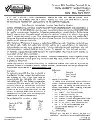
DETERMINING HOOD CLEARANCE<br />
NOTE: Check hood clearance be<strong>for</strong>e removing stock manifold.<br />
1. Use modeling clay or putty to make five small cones, two or three inches high.<br />
2. Position cones on air cleaner at front, rear, each side, and on center stud.<br />
3. Close hood to locked position and re-open.<br />
4. The height of the cones indicate the amount of clearance between the hood and the air cleaner. Record these<br />
measurements.<br />
AIR CLEANER<br />
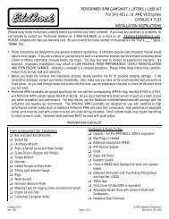
MANIFOLD & CARBURETOR HEIGHT VS. PRO-FLO HEIGHT<br />
1. Remove air cleaner.<br />
2. Lay a straightedge (such as a yardstick) across the top of the<br />
carburetor from front to back.<br />
3. Measure from block and manifold end seal surfaces to straightedge.<br />
4. Record these measurements (height A and height B).<br />
5. Add height A and height B and divide by two to get the average height.<br />
6. The <strong>Pro</strong>-<strong>Flo</strong> manifold (#<strong>3530</strong> & <strong>3531</strong>) measures: A = 5.40” by<br />
B = 6.65”. The air valve measures 2.25”.<br />
9. Compare the two measurements. If the <strong>Pro</strong>-<strong>Flo</strong> unit is taller, subtract<br />
this amount from the hood clearance figure to determine new hood<br />
clearance.<br />
CAUTION: You must maintain at least 1/2-inch clearance between the<br />
hood and air cleaner because of engine torque. If you have<br />
insufficient clearance, a low profile air cleaner may solve the problem.<br />
FUEL REQUIREMENTS<br />
Because the <strong>Pro</strong>-<strong>Flo</strong> system uses an Oxygen sensor, you must use unleaded fuel only. Leaded fuels will damage the O2 sensor. If<br />
you do use leaded fuel in your vehicle, do not install the O2 sensor and do not operate the vehicle in the closed loop fuel mode.<br />
EMISSION CONTROLS<br />
The <strong>Edelbrock</strong> <strong>Pro</strong>-<strong>Flo</strong> system will not accept stock emissions control systems. Check local laws <strong>for</strong> requirements be<strong>for</strong>e installing<br />
the <strong>Pro</strong>-<strong>Flo</strong> system. Not legal on pollution-controlled motor vehicles.<br />
©2005 <strong>Edelbrock</strong> Corporation<br />
Rev. 2/05<br />
CLAY CONE<br />
C<br />
B E<br />
A<br />
D<br />
2-3"<br />
FO RWARD<br />
4<br />
<strong>Pro</strong>-<strong>Flo</strong> EFI Installation Instructions<br />
B<br />
C<br />
E<br />
A<br />
D<br />
HEIGHT B<br />
HOOD CLEARANCE<br />
FORWARD<br />
FORWARD<br />
HEIGHT A<br />
Brochure #63-0273<br />
Catalog #<strong>3530</strong> & #<strong>3531</strong>
AUTOMATIC TRANSMISSION CHECK<br />
For best per<strong>for</strong>mance, economy, and emissions, the shift point must be checked be<strong>for</strong>e and after the manifold change.<br />
NOTE: This check should be per<strong>for</strong>med ONLY at a sanctioned drag strip or test track.<br />
With the shifter in Drive, accelerate to wide open throttle from a standing start. Hold in this position, noting speedometer MPH when<br />
the transmission makes the first 1-2 shift. After the <strong>Pro</strong>-<strong>Flo</strong> system has been installed, make the same test, again noting MPH of<br />
this first shift.<br />
The transmissions on certain vehicles require precise adjustments. We recommend that you consult a reputable transmission shop<br />
<strong>for</strong> final adjustments once the <strong>Pro</strong>-<strong>Flo</strong> system has been installed. Incorrect shift points can result in transmission damage.<br />
ENGINE CLEANING<br />
<strong>Edelbrock</strong> recommends that the <strong>Pro</strong>-<strong>Flo</strong> system be installed on a clean engine in order to prevent dirt from falling into the engine<br />
lifter valley or intake ports.<br />
1. Cover ignition. Use engine de-greaser and a brush to thoroughly clean the manifold and the area between the manifold and<br />
valve covers.<br />
2. Rinse with water and blow dry.<br />
EXHAUST MANIFOLD HEAT RISER VALVE & AIR INJECTION TUBES<br />
If your vehicle is equipped with an exhaust manifold heat riser valve (typically located on the passenger side of the vehicle below the<br />
exhaust manifold), remove the valve <strong>for</strong> proper operation. If applicable, any air injection tubes must be removed and holes in the<br />
exhaust manifold plugged <strong>for</strong> proper operation.<br />
HEADERS<br />
For best per<strong>for</strong>mance, headers are highly recommended. The remainder of the exhaust system should be free flowing, preferably a<br />
dual exhaust system using low back pressure mufflers.<br />
COOLING SYSTEM<br />
The minimum requirements <strong>for</strong> the thermostat are 180° but the ideal thermostat is 195°. When the vehicle is at 175 or below,<br />
system will stay in cold start mode and not per<strong>for</strong>m properly.<br />
©2005 <strong>Edelbrock</strong> Corporation<br />
Rev. 2/05<br />
5<br />
<strong>Pro</strong>-<strong>Flo</strong> EFI Installation Instructions<br />
Brochure #63-0273<br />
Catalog #<strong>3530</strong> & #<strong>3531</strong>
©2005 <strong>Edelbrock</strong> Corporation<br />
Rev. 2/05<br />
FUEL SYSTEM<br />
Because your <strong>Edelbrock</strong> <strong>Pro</strong>-<strong>Flo</strong> system controls fuel delivery very differently than a carburetor, some conversions to your fuel<br />
system are necessary. <strong>Pro</strong>-<strong>Flo</strong> electronic fuel injection requires high and constant fuel volume and fuel pressure. For this reason, a<br />
good primary fuel line is critical. The <strong>Pro</strong>-<strong>Flo</strong> system includes a 3/8-inch high pressure fuel line which must be used as the primary<br />
fuel line. The fuel that bypasses the injectors must be returned to the fuel tank via a return fuel line. If your vehicle is already<br />
equipped with a fuel pump bypass line, this line can be used as the return fuel line. If not, the original primary line may be used as<br />
the return line. If desired, an 8 foot length of 5/16 ID rubber hose is supplied <strong>for</strong> use as the return line.<br />
Many late-model cars are equipped with an additional fuel line which runs to a charcoal canister mounted on the driver side of the<br />
vehicle. This line MUST be re-installed after the fuel system conversion and MUST NOT be used as the return fuel line.<br />
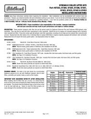
FUEL PUMP AND FILTER<br />
The <strong>Pro</strong>-<strong>Flo</strong> system uses a single <strong>Edelbrock</strong> high-pressure electric fuel pump which<br />
is capable of pumping 50 psi. The pump relay will shut down the pump if it does<br />
not receive an engine-run signal from the ECU, as in the case of a stall. This safety<br />
precaution is necessary when using a high-pressure fuel line. The provided fuel<br />
filter should be mounted between the engine compartment and the fuel pump to<br />
allow fuel to be pushed through the filter rather than drawn through. Electrical<br />
connectors should face the front of vehicle.<br />
FUEL PRESSURE REGULATOR<br />
Fuel pressure is as important as fuel volume, particularly in fuel injection. The <strong>Pro</strong>-<br />
<strong>Flo</strong> fuel pressure regulator maintains a constant pressure at the injectors with a<br />
spring loaded by-pass to the return fuel line. Manifold pressure references the<br />
regulator diaphragm to maintain constant pressure across all 8 injectors,<br />
regardless of fluctuating manifold pressure (vacuum) level. The fuel that is not<br />
injected is returned to the fuel tank via the return fuel line.<br />
RETURN FUEL LINE<br />
Due to the high fuel pressure used by the <strong>Pro</strong>-<strong>Flo</strong> system, the supplied 3/8-inch high pressure fuel line MUST be used as the<br />
primary fuel line, and a bypass fuel return line must be installed. There are three options <strong>for</strong> installing a bypass return line.<br />
1. Use the 5/16 rubber fuel line provided with the system as the fuel return line.<br />
6<br />
<strong>Pro</strong>-<strong>Flo</strong> EFI Installation Instructions<br />
Engine<br />
Side<br />
2. Use the vehicle’s existing primary line as the fuel return line with modification to the pick up as described below.<br />
3. Use the vehicle’s existing return line (if so equipped) as the fuel return line. This option applies only to vehicles previously<br />
equipped with fuel injection. If the vehicle is not already equipped with a return line, some fuel tank modifications are required<br />
<strong>for</strong> routing the return line through the sending unit plate back into the tank. The first two methods listed below require some<br />
welding and should be done by a professional radiator or fuel system repair shop.<br />
Tank<br />
Side<br />
Brochure #63-0273<br />
Catalog #<strong>3530</strong> & #<strong>3531</strong>
RUBBER RETURN LINE METHOD<br />
Drill a 5/16-inch hole in the sending unit plate adjacent to where the main line enters the tank. This will be the hole <strong>for</strong> your return<br />
line. Insert a short length of 5/16-inch hard line (available at most radiator shops) into the hole and weld it to the sending unit plate.<br />
The hard line should extend through the hole 1 to 2 inches on each side of the plate. Connect a length (at least 4 inches) of 5/16inch<br />
rubber return line hose to the hard line that will extend into the tank. Connect the rubber line to the fuel pickup line using tie<br />
wraps.<br />
©2005 <strong>Edelbrock</strong> Corporation<br />
Rev. 2/05<br />
RUBBER HOSE METHOD<br />
BULKHEAD FITTING METHOD<br />
Drill a 9/16-inch hole in the sending unit plate adjacent to where the main line enters the tank. This will be the hole <strong>for</strong> your return<br />
line. Insert a #6 AN bulkhead fitting (available at most speed shops) into the hole, the narrow end of the fitting on the inside of the<br />
plate. Apply a metal washer with inter O-ring <strong>for</strong> seal. Connect a length (at least 4 inches) of flexible return line (rubber or braided<br />
hose) to the fitting end. Connect the return line to the fuel pickup line using tie wraps.<br />
NOTE: THIS METHOD REQUIRES NO WELDING OF THE FUEL SYSTEM.<br />
NOTE: Whichever method you use to install the return fuel line,<br />
be careful to keep the end of the line away from the fuel pickup,<br />
as shown. Otherwise, aerated return fuel can be drawn into the<br />
pickup.<br />
7<br />
<strong>Pro</strong>-<strong>Flo</strong> EFI Installation Instructions<br />
Brochure #63-0273<br />
Catalog #<strong>3530</strong> & #<strong>3531</strong>
HARD RETURN LINE METHOD<br />
Drill a 5/16-inch hole in the sending unit plate adjacent to where the main line, enters the tank. This will be the hole <strong>for</strong> your return<br />
line. Insert a length of 5/16-inch hard line (available at most radiator shops) into the hole and weld it to the sending unit plate. The<br />
hard line should extend through the hole 1 to 2 inches on the outside of the plate. On the inside of the plate, the hard line should<br />
follow the contours of the fuel pickup line. Bend the end of the return line away from the sock on the end of the fuel pickup line.<br />
Solder or weld the return hard line to the fuel pickup line.<br />
©2005 <strong>Edelbrock</strong> Corporation<br />
Rev. 2/05<br />
HARDLINE METHOD<br />
8<br />
<strong>Pro</strong>-<strong>Flo</strong> EFI Installation Instructions<br />
BULKHEAD FITTING METHOD<br />
Brochure #63-0273<br />
Catalog #<strong>3530</strong> & #<strong>3531</strong>
NOTE: ALL WELDING AND SOLDERING OF THE FUEL SYSTEM MUST BE<br />
PERFORMED BY A PROFESSIONAL RADIATOR OR FUEL SYSTEM REPAIR SHOP.<br />
FUEL SYSTEM INSTALLATION<br />
1. Drain the fuel tank.<br />
2. Remove all fuel lines from the tank and from the carburetor.<br />
3. Remove the fuel tank.<br />
NOTE: While the fuel tank is removed from the car, it is recommended that it be<br />
professionally cleaned in order to remove any rust or dirt that may have accumulated<br />
inside and which could damage the injectors.<br />
4. Remove the sending unit from the fuel tank. Refer to the RETURN FUEL LINE methods<br />
above <strong>for</strong> installing the bypass fuel return line.<br />
5. Install the provided 3/8-inch primary fuel line directly above the original line, which may<br />
now serve as a return line. Use large radius bends. Avoid the exhaust pipe and any<br />
sharp edges.<br />
NOTE: The 3/8-inch high pressure fuel line supplied with the <strong>Pro</strong>-<strong>Flo</strong> system must be<br />
used as the primary fuel line.<br />
6. If you do not use the original fuel as the return line, route the return line directly<br />
alongside the provided 3/8-inch primary fuel line.<br />
NOTE: In the application shown to the right, we routed our fuel supply and return lines<br />
down the passenger side of the engine and along the passenger side frame rail.<br />
7. Mount the fuel pump between the tank and the fuel filter as low and as close to the fuel<br />
tank as possible. The pump is directional. Electrical connectors should face the front of<br />
vehicle. The fuel pump needs to be at or below the level of fuel in the tank.<br />
8. Mount the fuel filter between the fuel pump and the engine.<br />
9. Re-install the modified sending unit plate to the clean fuel tank.<br />
10. Re-install the fuel tank.<br />
11. Attach the primary line and return line to the sending unit plate on the tank.<br />
12. Re-attach all other fuel lines at the tank (vapor purge lines, etc., if so equipped).<br />
13. Secure the primary and return fuel lines with the provided tie-wraps, or with Adel clamps<br />
if available.<br />
14. Re-attach all fuel lines to the induction system once it has been installed.<br />
15. Use the 10-foot wiring harness to connect the fuel pump to the Main <strong>System</strong> Harness.<br />
Route the harness away from the exhaust pipe and any sharp edges. This harness may<br />
be cut to length. Replacement terminals are provided with the <strong>Pro</strong>-<strong>Flo</strong> system. Cover<br />
the connection to the positive terminal with the sleeve and tie wrap provided. Refer to<br />
the MAIN SYSTEM HARNESS section of this manual <strong>for</strong> details.<br />
16. Be<strong>for</strong>e starting the engine, turn the ignition key to the “ON” position 4 or 5 times to<br />
prime the electric fuel pump, fuel lines, and fuel rails. You should hear the pump run <strong>for</strong><br />
approximately 2 seconds each time. Check the entire fuel system <strong>for</strong> leaks. Refer to the<br />
SYSTEM START-UP section of this manual <strong>for</strong> details.<br />
©2005 <strong>Edelbrock</strong> Corporation<br />
Rev. 2/05<br />
9<br />
<strong>Pro</strong>-<strong>Flo</strong> EFI Installation Instructions<br />
Brochure #63-0273<br />
Catalog #<strong>3530</strong> & #<strong>3531</strong>
©2005 <strong>Edelbrock</strong> Corporation<br />
Rev. 2/05<br />
INDUCTION SYSTEM<br />
The <strong>Edelbrock</strong> <strong>Pro</strong>-<strong>Flo</strong> system delivers fuel and air to the engine via the induction system consisting primarily of a manifold, 4-barrel<br />
air valve, fuel rails, and fuel injectors. The induction system is fully assembled, tested, seal checked, and flowed at the factory and<br />
is as easy to install as a manifold. DO NOT DISASSEMBLE any of these components during installation, unless instructed.<br />
FUEL RAILS<br />
The extruded aluminum rail assembly routes the high pressure fuel to the injectors. Aluminum rails have an advantage over soft<br />
rails both in terms of style and safety.<br />
4-BARREL AIR VALVE<br />
The <strong>Pro</strong>-<strong>Flo</strong> system uses a progressive linkage valve body<br />
with four throttles arranged in a conventional 4-barrel<br />
pattern, with staged secondaries. The air valve can flow up<br />
to 1000 cfm at 1.5" of mercury when wide open.<br />
INTAKE MANIFOLD<br />
The new <strong>Edelbrock</strong> manifold used with the <strong>Pro</strong>-<strong>Flo</strong> system is<br />
very similar to the successful Victor Jr. style of highper<strong>for</strong>mance<br />
single-plane manifold, but has been designed<br />
specifically <strong>for</strong> electronic fuel injection applications.<br />
10<br />
<strong>Pro</strong>-<strong>Flo</strong> EFI Installation Instructions<br />
FUEL INJECTORS<br />
The <strong>Pro</strong>-<strong>Flo</strong> system uses high impedance Pico-type fuel<br />
injectors. These injectors are capable of flowing 29 lbs./hr.<br />
at 45 psi. The injectors mount directly onto the manifold, one<br />
at each port, <strong>for</strong> fuel delivery that is precisely controlled and<br />
instantaneously injected.<br />
Brochure #63-0273<br />
Catalog #<strong>3530</strong> & #<strong>3531</strong>
PRE-INSTALLATION<br />
Be<strong>for</strong>e installing the induction system, take the following steps to ensure successful installation and per<strong>for</strong>mance:<br />
1. Check all components thoroughly <strong>for</strong> damage.<br />
2. Make sure all throttle linkages open entirely and close freely.<br />
3. Make sure all fuel inlet and vacuum ports are free from packing material.<br />
4. Check the installation kit <strong>for</strong> proper parts.<br />
REMOVING THE STOCK CARBURETOR AND MANIFOLD<br />
1. Disconnect battery.<br />
2. For ease of installation, keep all parts in order.<br />
CAUTION: Do not remove manifold if engine is hot.<br />
3. Drain the radiator coolant.<br />
4. Remove gas cap to relieve pressure. Disconnect fuel line and plug. Replace gas cap.<br />
5. Disconnect all linkage from carburetor such as throttle, throttle springs, transmission, cruise control and automatic choke.<br />
6. Tag and remove coil wires and sensor wires.<br />
7. Remove previously marked vacuum lines.<br />
8. Remove radiator hose, thermostat housing and thermostat, if mounted on manifold.<br />
9. Remove all brackets from the manifold.<br />
10. Loosen or remove valve cover bolts <strong>for</strong> manifold removal and replacement. It may be necessary to replace valve cover<br />
gaskets, if broken, to prevent oil leakage.<br />
PORT SURFACE CLEANING<br />
When cleaning old gaskets from head surfaces, lay rags in the lifter valley and stuff<br />
paper into the ports, to prevent pieces of the old gasket from falling into ports and<br />
combustion chambers. When clean, remove paper, making sure that all particles fall<br />
on the rags in the lifter valley. Remove rags, and wipe surfaces clean with rags<br />
soaked in lacquer thinner in order to remove oil or grease.<br />
NOTE: This procedure is necessary to ensure proper sealing.<br />
INSTALLING FITTINGS, PIPE PLUGS, AND STUDS<br />
Do not over-tighten or cross-thread fittings, pipe plugs, studs, or bolts in your<br />
aluminum manifold. Damage to threads or a cracked mounting boss may result<br />
unless caution is used when installing accessories.<br />
Use high quality pipe thread sealant on all threads. Install fittings from your stock manifold.<br />
©2005 <strong>Edelbrock</strong> Corporation<br />
Rev. 2/05<br />
11<br />
<strong>Pro</strong>-<strong>Flo</strong> EFI Installation Instructions<br />
Brochure #63-0273<br />
Catalog #<strong>3530</strong> & #<strong>3531</strong>
GASKET SURFACE PREPARATION<br />
CAUTION: Replace all gaskets as recommended. We recommend using an OEM style metal pan intake gasket ONLY. Failure to use<br />
a valley pan will result in excessive oil consumption and improper manifold fit. DO NOT use competition type cork or rubber<br />
gaskets, or those that do not include a metal valley pan. Oil and/or coolant leaks may occur with the use of other style gaskets.<br />
1. Remove Fuel rails and Injectors: Fuel injectors and fuel rails are assembled on the manifold and pressure tested. Installing<br />
the intake requires the removal of both fuel rails. Remove the two 1/4" bolts per fuel rail and flat washers. Carefully remove<br />
one fuel rail at a time and any remaining injectors from intake manifold.<br />
2. Check gaskets on head surface and manifold to make sure they fit correctly.<br />
3. Install the supplied PCV baffle plate with the supplied #8 x 3/8”<br />
drive screws. Tap them in gently until flush with the baffle plate.<br />
4. Apply Loctite 598 OEM High Temperature Silicone Gasket around<br />
water passages on head surface.<br />
5. Carefully place the pan gasket on head surface, aligning ports and<br />
bolt holes.<br />
6. <strong>Edelbrock</strong> recommends the use of Loctite 598 OEM High<br />
Temperature Silicone Gasket instead of end seal gaskets. Apply a<br />
1/4-inch thick bead of sealant across each end seal surface,<br />
overlapping the intake gasket at the four corners.<br />
NOTE: Use the recommended silicon sealer. Others may damage<br />
the O2 sensor. This method eliminates end seal slippage and<br />
deterioration.<br />
7. Apply RTV gasket sealer around water passages on the manifold.<br />
8. Surfaces will become tacky to the touch within a few minutes.<br />
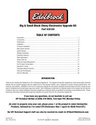
INDUCTION SYSTEM INSTALLATION<br />
1. Carefully position manifold and air valve on engine, centering bolt<br />
holes with the bolt holes in the head.<br />
2. Apply thread sealer or Teflon tape to bolt threads where exposed 10 9 3 2 7 8<br />
3.<br />
to water or oil.<br />
Hand tighten all bolts.<br />
Firing Order: 1-8-4-3-6-5-7-2<br />
4. Torque all manifold bolts to 25 ft/lbs. Torque in the sequence as shown.<br />
5. Install Fuel rails and Injectors: Lubricate injector O-rings (top and bottom) with Oring<br />
type lubricant be<strong>for</strong>e sliding them into fuel rails. Push injectors into rails, making<br />
sure that the electrical connectors on injector bodies face up. Place fuel rail with<br />
pressure regulator on passenger's side with regulator toward rear of engine. Push<br />
down with enough <strong>for</strong>ce to seat lubricated O-rings in manifold, making sure not to<br />
damage O-rings. Once installed, secure rails with 1/4" bolts and flat washers to 8 ftlbs(<br />
96 In-lbs). When properly installed, the injectors should rotate freely by hand.<br />
6. Re-connect throttle linkage and springs, transmission, cruise control, and fuel lines.<br />
Check all linkage <strong>for</strong> smooth throttle operation from idle to Wide Open Throttle.<br />
Note: Do not install with a throttle rod, use a cable actuated throttle. Throttle rods will cause<br />
engine surge as the engine moves in its mounts.<br />
7. Re-tighten the valve cover bolts.<br />
©2005 <strong>Edelbrock</strong> Corporation<br />
Rev. 2/05<br />
12<br />
12<br />
<strong>Pro</strong>-<strong>Flo</strong> EFI Installation Instructions<br />
PCV Baffle<br />
Plate<br />
11<br />
4<br />
1<br />
5<br />
6<br />
Brochure #63-0273<br />
Catalog #<strong>3530</strong> & #<strong>3531</strong>
©2005 <strong>Edelbrock</strong> Corporation<br />
Rev. 2/05<br />
SENSORS<br />
The <strong>Edelbrock</strong> <strong>Pro</strong>-<strong>Flo</strong> system interprets overall engine operating conditions and fuel/spark requirements based on readings from<br />
sensors that measure specific engine conditions.<br />
The <strong>Pro</strong>-<strong>Flo</strong> system includes five sensors:<br />
1) Manifold Absolute Pressure<br />
2) Manifold Air Temperature<br />
3) Coolant Temperature<br />
4) Throttle Position<br />
5) Exhaust Oxygen (O2)<br />
These sensors, with the exception of the O2 and MAT (Manifold Air Temperature) sensors are designed as an integral part of the<br />
induction system and require no installation. The O2 sensor must be installed on the exhaust pipe near the engine with a welded<br />
fitting, and the MAT sensor must be installed into the air cleaner base.<br />
MANIFOLD ABSOLUTE PRESSURE SENSOR<br />
The Manifold Absolute Pressure sensor, mounted on the air valve with a<br />
bracket, converts air pressure (load) in the manifold, to an analog signal sent<br />
to the ECU. For more in<strong>for</strong>mation on Manifold Absolute Pressure, refer to the<br />
section on Speed Density Electronic Engine Management. This sensor is<br />
connected to the Main <strong>System</strong> Harness.<br />
MANIFOLD AIR TEMPERATURE SENSOR<br />
The Manifold Air Temperature sensor, is a<br />
thermistor device which measures air<br />
temperature. This sensor must be installed<br />
into the air cleaner base. Punch a 3/4” hole<br />
in air cleaner base, debur any sharp edges,<br />
install MAT sensor grommet, then slide<br />
sensor into grommet. This sensor is<br />
connected to the Main <strong>System</strong> Harness.<br />
13<br />
<strong>Pro</strong>-<strong>Flo</strong> EFI Installation Instructions<br />
Brochure #63-0273<br />
Catalog #<strong>3530</strong> & #<strong>3531</strong>
COOLANT TEMPERATURE SENSOR<br />
The Coolant Temperature Sensor is a thermistor device like the<br />
Manifold Air Temperature sensor. Resistance varies as coolant<br />
temperature rises and lowers. The Coolant Temperature Sensor is<br />
located at the front of the manifold on the passenger side, and is<br />
connected to the Main <strong>System</strong> Harness..<br />
OXYGEN (O2) SENSOR<br />
An oxygen sensor, installed on the header collector pipe, measures<br />
exhaust gas oxygen content and is used by the ECU to manage fuel<br />
delivery under closed loop control. Installing the sensor requires<br />
drilling a 1/2-inch hole in the passenger-side header collector. The<br />
sensor threads into the provided fitting which must be professionally<br />
welded into place. The red-lean/green-rich light on the Calibration<br />
Module is also controlled by the O2 sensor. The O2 sensor is<br />
connected to the Main <strong>System</strong> Harness. For installation details, refer<br />
to the FUEL SYSTEM section of this manual.<br />
NOTE: Prior to installing your O2 sensor, check the wires leading into<br />
the weather pack plug and make sure the odd colored wire is<br />
in the middle.<br />
©2005 <strong>Edelbrock</strong> Corporation<br />
Rev. 2/05<br />
14<br />
<strong>Pro</strong>-<strong>Flo</strong> EFI Installation Instructions<br />
THROTTLE POSITION SENSOR<br />
The Throttle Position Sensor, an integral part of the <strong>Pro</strong>-<strong>Flo</strong><br />
throttle body, measures throttle angle. This sensor requires<br />
adjustment as described in the SYSTEM START-UP section of<br />
this manual. It is connected to the Main <strong>System</strong> Harness.<br />
Brochure #63-0273<br />
Catalog #<strong>3530</strong> & #<strong>3531</strong>
©2005 <strong>Edelbrock</strong> Corporation<br />
Rev. 2/05<br />
O2 SENSOR INSTALLATION<br />
The exhaust gas oxygen content is determined by the oxygen sensor. The sensor signals the ECU, which compensates when the<br />
air/fuel mixture is either rich or lean.<br />
NOTE: It is recommended that the O2 sensor installation be per<strong>for</strong>med by a professional muffler shop.<br />
1. Double check header gaskets, replacing if necessary.<br />
2. Drill a 1/2-inch to 9/16-inch hole in the passenger-side header collector reducer, as close to the header collector flange as<br />
possible (1" to 3" away).<br />
NOTE: Be<strong>for</strong>e drilling, make sure the O2 sensor will be mounted horizontally and within reach of the harness connector. Check<br />
to ensure adequate clearance <strong>for</strong> the sensor, taking into consideration engine movement.<br />
3. Fit the provided fitting into the hole in the exhaust pipe and weld into place.<br />
4. Once it has been welded into place, clean the threads in the center of the fitting. It is important that the threads are clean and<br />
free of paint or ceramic coating, in order to provide a good ground <strong>for</strong> the O2 sensor.<br />
5. Thread the O2 sensor into the fitting. Apply the supplied high-heat anti-seize compound to the sensor threads be<strong>for</strong>e installing<br />
the O2 sensor into the fitting.<br />
NOTE: The O2 sensor has 18mm x 1.25 spark plug threads.<br />
6. Attach the O2 sensor to the main system harness. Refer to the MAIN SYSTEM HARNESS section of this manual.<br />
NOTE: UNLEADED FUEL MUST BE USED ONCE THE O2 SENSOR HAS BEEN INSTALLED.<br />
COATED HEADERS: Use a digital OHM meter to measure the resistance between cylinder head bolt and the nut of the installed<br />
O2 sensor. The reading should be less than 2 OHMS. If it is more, you need to provide a ground to the O2 sensor mount.<br />
15<br />
<strong>Pro</strong>-<strong>Flo</strong> EFI Installation Instructions<br />
Brochure #63-0273<br />
Catalog #<strong>3530</strong> & #<strong>3531</strong>
©2005 <strong>Edelbrock</strong> Corporation<br />
Rev. 2/05<br />
MAIN SYSTEM HARNESS<br />
If the ECU is the brain of the <strong>Edelbrock</strong> <strong>Pro</strong>-<strong>Flo</strong> system, the Main <strong>System</strong> Harness is the central nervous system. The harness is<br />
constructed with SAE grade wires and the most up-to-date Weatherpak connectors.<br />
This diagram illustrates the entire <strong>Pro</strong>-<strong>Flo</strong> Main <strong>System</strong> Harness.<br />
Cal<br />
ECU<br />
<strong>3530</strong> & <strong>3531</strong> Ignition Coil<br />
<strong>3530</strong> & <strong>3531</strong><br />
Pink<br />
Brn<br />
16<br />
<strong>Pro</strong>-<strong>Flo</strong> EFI Installation Instructions<br />
Fuel Pump<br />
Brochure #63-0273<br />
Catalog #<strong>3530</strong> & #<strong>3531</strong>
To Calibration<br />
Module<br />
©2005 <strong>Edelbrock</strong> Corporation<br />
Rev. 2/05<br />
To ECM<br />
(Computer)<br />
Driver Side<br />
Injectors<br />
1,3,5,7<br />
To Coil<br />
Fuel Pump<br />
MAT Sensor<br />
O2 Sensor<br />
Engine Coolant<br />
12-volt<br />
Battery Power<br />
IAC (Idle Air<br />
Control)<br />
17<br />
<strong>Pro</strong>-<strong>Flo</strong> EFI Installation Instructions<br />
Passenger Side<br />
Injectors<br />
2,4,6,8<br />
Fuses - Fuel<br />
Pump Relay<br />
TPS (Throttle<br />
Position Sensor)<br />
Tach Leed<br />
MAP Sensor<br />
(Manifold Air<br />
Pressure)<br />
Ground<br />
Distributor<br />
Ignition Amplifier<br />
Switched 12-volt<br />
Power<br />
MOPAR AND <strong>AMC</strong> WIRING HARNESS<br />
Brochure #63-0273<br />
Catalog #<strong>3530</strong> & #<strong>3531</strong>
INSTALLATION<br />
1. Inspect the Main <strong>System</strong> Harness, making sure that all connectors and grounds are properly in place.<br />
2. Because the harness extends from the engine compartment into the passenger compartment, a hole must be drilled in the<br />
firewall on the passenger side. Cut two overlapping 1 1/4-inch holes on a 1-inch center in the firewall. Saw the pointed edges<br />
to create an oval-shaped hole.<br />
NOTE: An alternative to this method is to cut a single 1 3/4 inch hole.<br />
3. Extend the fuel pump relay, ECU connector, and Calibration Module relay through the firewall hole into the passenger<br />
compartment.<br />
NOTE: The T-connectors at the joints of the Main <strong>System</strong> Harness are closed by snap fasteners which can be opened by hand<br />
or with a flathead screwdriver. Once open, the T-connectors can be rotated <strong>for</strong> ease of installation, if necessary.<br />
4. The 3 1/2 x 2 1/4-inch aluminum plate included on the harness mounts over the firewall hole using four hex head sheet metal<br />
screws.<br />
NOTE: Start the screw holes with a pointed punch or small drill.<br />
5. The wire harness is assembled with the aluminum plate flush against a T-connector. The black plastic casing on the wire<br />
harness can be cut to allow the plate to slide up the harness to the correct location. Once the harness is in place, the casing<br />
should be reattached on both sides of the firewall.<br />
CAUTION: When feeding the wire harness through the firewall, be careful to not damage the wires against the cut sheet metal.<br />
6. A rubber grommet is provided to protect the wires in the aluminum plate. Use RTV to seal the plate to the firewall.<br />
7. Install all connectors according to the list and diagrams. The harness has been designed so that each connector is unique and<br />
will fit only to its correct match. There is only one possible installation combination; it cannot be installed incorrectly.<br />
©2005 <strong>Edelbrock</strong> Corporation<br />
Rev. 2/05<br />
18<br />
<strong>Pro</strong>-<strong>Flo</strong> EFI Installation Instructions<br />
The Throttle Position sensor attaches to the main harness .<br />
Brochure #63-0273<br />
Catalog #<strong>3530</strong> & #<strong>3531</strong>
The Manifold Absolute Pressure sensor<br />
attaches to the main harness.<br />
The Manifold Air Temperature sensor attaches to the<br />
main harness.<br />
©2005 <strong>Edelbrock</strong> Corporation<br />
Rev. 2/05<br />
19<br />
<strong>Pro</strong>-<strong>Flo</strong> EFI Installation Instructions<br />
The Coolant Temperature sensor attaches to the<br />
main harness.<br />
Only the fuel injector connectors are identical, but<br />
they are placed in logical sequence. Refer to the<br />
diagram when installing the harness connectors to<br />
the fuel injectors.<br />
Brochure #63-0273<br />
Catalog #<strong>3530</strong> & #<strong>3531</strong>
©2005 <strong>Edelbrock</strong> Corporation<br />
Rev. 2/05<br />
The IAC is attached to the main wiring harness.<br />
The ignition amplifier is attached to the main harness with the connector at left side of lower diagram. The ignition amplifier should<br />
be mounted on the firewall, or on the passenger fender well. The KEY ON (Start/Run power) wire (pink) should be connected to the<br />
factory positive (+) coil wire. If you have a ballast resistor in your factory coil wiring, you should remove the ballast resistor and<br />
connect the KEY ON wire to the wire coming into the positive (+) side of the ballast resistor. REFER TO VEHICLE REPAIR MANUAL<br />
FOR WIRING DIAGRAM, IF NECESSARY.<br />
TO IGN AMP<br />
TACHOMETER LEAD<br />
The coil is attached to the main harness. We strongly recommend using an E-Core type (non-ballast resistor) coil as shown below.<br />
These are available through most per<strong>for</strong>mance ignition parts suppliers. The coil attaches via the connector shown below. If using a<br />
standard style coil, cut the connector off and use ring type connectors.<br />
TO COIL<br />
TO COIL<br />
20<br />
<strong>Pro</strong>-<strong>Flo</strong> EFI Installation Instructions<br />
TO MAIN<br />
HARNESS<br />
ATTACHES TO OEM<br />
START/RUN POWER<br />
(OEM POSITIVE “+” COIL WIRE)<br />
TO MAIN HARNESS<br />
TO MAIN HARNESS<br />
Brochure #63-0273<br />
Catalog #<strong>3530</strong> & #<strong>3531</strong>
ELECTRONIC CONTROL UNIT /SYSTEM ECU<br />
©2005 <strong>Edelbrock</strong> Corporation<br />
Rev. 2/05<br />
Attach the distributor to the main harness as shown above.<br />
The Electronic Control Unit (ECU) must be mounted away from moisture, excessive heat,<br />
or vibration. Underneath the dashboard on the passenger side, or behind the glove box are<br />
recommended locations.<br />
The connector on left end (as drawn) of this 10-foot fuel pump wiring harness attaches to connector on the Main <strong>System</strong> Harness.<br />
The two connectors on the right connect to the positive (+) and negative (-) terminals on the fuel pump. A sleeve and tie-wrap are<br />
provided to fit over the positive terminal once the connector is installed. This sleeve prevents the clamp from shorting the fuel pump<br />
terminals.<br />
21<br />
<strong>Pro</strong>-<strong>Flo</strong> EFI Installation Instructions<br />
Brochure #63-0273<br />
Catalog #<strong>3530</strong> & #<strong>3531</strong>
.<br />
IGNITION AMPLIFIER<br />
©2005 <strong>Edelbrock</strong> Corporation<br />
Rev. 2/05<br />
IGNITION SYSTEM<br />
The <strong>Pro</strong>-<strong>Flo</strong> system uses the <strong>Edelbrock</strong> #3518 Ignition Amplifier, which must be<br />
mounted on a flat surface in the engine compartment away from exhaust<br />
headers or other areas that generate heat. The wheel well panel and firewall are<br />
ideal locations. The Ignition Amplifier is to be connected to the Main <strong>System</strong><br />
Harness.<br />
DISTRIBUTOR TESTING<br />
1. Install the ECU and wiring harness and make all connections except the distributor.<br />
2. Disconnect electrical connections at the fuel pump. Unplug the 10-foot fuel pump harness from the Main <strong>System</strong> Harness.<br />
Refer to the MAIN SYSTEM HARNESS section of this manual <strong>for</strong> details.<br />
3. Turn the key to the ON position without starting the engine. Check the Idle Air Control (IAC) solenoid clicks on and off <strong>for</strong><br />
approximately 2 seconds.<br />
4. The <strong>Pro</strong>-<strong>Flo</strong> Calibration Module will receive power and display an RPM: 0 reading, among other parameters.<br />
5. Connect the distributor to the wiring harness and spin the<br />
distributor gear by hand. If the distributor sensor is operating<br />
properly, the Calibration Module will display an RPM reading<br />
greater than 0. When the distributor stops spinning, the<br />
Calibration Module may display NO COMMUNICATION <strong>for</strong><br />
approximately 2 seconds. This is normal and indicates that the<br />
ECU is waiting <strong>for</strong> the next distributor signal be<strong>for</strong>e the allowed<br />
time expires.<br />
6. If an RPM greater than zero is indicated in step 5, install the<br />
distributor.<br />
INSTALLING THE DISTRIBUTOR<br />
1. Note: The distributor drive gear is not included and the OEM gear, or a new replacement must be installed onto the base of the<br />
supplied Mallory distributor be<strong>for</strong>e installing the distributor (Use a new gear only if installing a new camshaft at this time. Use<br />
of a new gear on a used camshaft may result in drive gear or camshaft failure). Begin by removing the OEM gear from the<br />
stock distributor by pressing or punching out the roll pin. Remove the distributor cap and rotor on the Mallory distributor be<strong>for</strong>e<br />
beginning the gear installation.<br />
2. Grasp the Mallory distributor base at the housing and push on the shaft from above to remove all the slack.<br />
22<br />
<strong>Pro</strong>-<strong>Flo</strong> EFI Installation Instructions<br />
Brochure #63-0273<br />
Catalog #<strong>3530</strong> & #<strong>3531</strong>
3. Install the supplied .030” thrust washer and the OEM gear onto the<br />
new distributor by sliding them onto the shaft. Push on the shaft from<br />
above while holding the thrust washer and gear against the housing to<br />
remove any slack.<br />
4. Pull the gear away from the housing enough to insert a .020” feeler<br />
gauge between the thrust washer and the gear. After inserting the<br />
gauge, press on the shaft from above while holding the gear against<br />
the gauge to remove any slack.<br />
5. Using the hole in the OEM gear as a guide, drill a hole through the<br />
Mallory shaft using a drill bit the exact size as the hole in the OEM<br />
distributor shaft. (Note: Ensure that all slack is removed, and the<br />
feeler gauge remains in place while drilling. We strongly recommend<br />
using a drill press <strong>for</strong> this procedure.)<br />
6. Press a new roll pin into the gear/shaft. Remove the feeler gauge. The gear should be pinned to the shaft, and the gear should<br />
move .010” to .030” relative to the housing.<br />
7. Rotate the crankshaft until the #1 cylinder is coming up on the compression stroke. Stop turning when the crank is at 10<br />
degrees be<strong>for</strong>e TDC.<br />
8. Apply assembly lubricant to the drive gear and thrust washer and insert the distributor into the engine. Install the distributor so<br />
that #1 on the cap is positioned where cylinder #1 was on your previous distributor, or to the position you will be using <strong>for</strong> the<br />
#1 cylinder spark plug wire. Regardless of the position used, remember to install your spark plug wires according to the factory<br />
firing order listed in the “INDUCTION SYSTEM INSTALLATION” section of this manual.<br />
9. Make sure that the distributor seats down completely and has fully engaged the oil pump drive.<br />
NOTE: You may need to repeat step 8 to make sure the oil pump drive is engaged.<br />
10. Lift the rotor by hand to make sure that there is adequate endplay. Lack of endplay indicates that the rotor shaft is bottomed<br />
out on the oil pump shaft.<br />
10. Lightly tighten the hold down clamp so that the distributor can still be turned to determine final setting when checking the<br />
timing.<br />
11. Re-attach the distributor cap, with the rotor pointing to #1, and connect start-run power to the ignition coil.<br />
12. The distributor is connected to the MAIN SYSTEM HARNESS.<br />
Insert .020” feeler gauge<br />
to provide clearance.<br />
©2005 <strong>Edelbrock</strong> Corporation<br />
Rev. 2/05<br />
Use hole in drive gear as a drill guide.<br />
Pin gear to shaft with roll pin.<br />
23<br />
<strong>Pro</strong>-<strong>Flo</strong> EFI Installation Instructions<br />
Push here to<br />
remove slack<br />
OEM Drive<br />
Gear<br />
Push<br />
When installing distributor, align rotor<br />
with the position on the distributor cap<br />
being used <strong>for</strong> cylinder #1<br />
Grasp<br />
Housing<br />
Brochure #63-0273<br />
Catalog #<strong>3530</strong> & #<strong>3531</strong>
©2005 <strong>Edelbrock</strong> Corporation<br />
Rev. 2/05<br />
OTHER APPLICATIONS<br />
The <strong>Pro</strong>-<strong>Flo</strong> system has been designed and calibrated using a 304 <strong>AMC</strong> V8 engine with an <strong>Edelbrock</strong> Per<strong>for</strong>mer-Plus camshaft and<br />
tubular headers as a baseline. A calibration is also available <strong>for</strong> the 401 <strong>AMC</strong> V8 using <strong>Edelbrock</strong> <strong>AMC</strong> cylinder heads and a<br />
Per<strong>for</strong>mer RPM camshaft.<br />
It is unlikely that every engine on which the <strong>Pro</strong>-<strong>Flo</strong> system is installed will match these particular combinations. The system can<br />
be used with similar applications, as long as the correct chip matching your cam profile is installed in the computer and necessary<br />
fuel calibration adjustments are made. If your <strong>AMC</strong> engine does not match the above specifications, it may require more tuning<br />
adjustments. For further in<strong>for</strong>mation refer to the SYSTEM SET-UP SECTION of the Owner’s Manual.<br />
If you are running a stock camshaft and/or you are not using tubular headers, it may be necessary to reduce fuel at WOT from 4000<br />
rpm and up. Refer also to the SYSTEM SET-UP section in the Owner’s Manual. Use the FUEL @ WOT screens (located under FUEL<br />
MODIFIERS) to adjust the fuel at each available RPM.<br />
WARNING: Watch the Rich/Lean light on the Calibration Module. If the light indicates a lean condition (red) <strong>for</strong> more than a<br />
fraction of a second at 0-6” vacuum or at WOT you are too lean <strong>for</strong> safe engine operation at full load.<br />
SYSTEM START-UP<br />
Once the <strong>Edelbrock</strong> <strong>Pro</strong>-<strong>Flo</strong> system has been installed, there are a few procedures you must follow to break-in the system.<br />
Carefully per<strong>for</strong>ming these break-in procedures will ensure best results and optimal per<strong>for</strong>mance.<br />
Use this checklist to double-check the following areas BEFORE starting the car:<br />
❑ Has the battery been reconnected?<br />
❑ Has the radiator been refilled with coolant?<br />
❑ Has the gas tank been refilled?<br />
❑ Has the oil been replaced?<br />
❑ Have all linkages been reconnected?<br />
❑ Have all wiring harness connectors been connected?<br />
❑ Have all fuel lines been reconnected?<br />
❑ Has the exhaust system been completely re-installed?<br />
❑ Has the O2 sensor been installed and connected?<br />
❑ Have resistor type spark plugs been installed?<br />
Distributor Test<br />
Refer to the “IGNITION SYSTEM” section of this manual, under “DISTRIBUTOR TESTING” <strong>for</strong> the proper procedure.<br />
24<br />
<strong>Pro</strong>-<strong>Flo</strong> EFI Installation Instructions<br />
Brochure #63-0273<br />
Catalog #<strong>3530</strong> & #<strong>3531</strong>
Priming The Fuel Pump<br />
Be<strong>for</strong>e the engine is started, the fuel pump must be primed to pressurize the system and purge the fuel line of all air.<br />
1. Turn ignition key to the “ON” position. You should hear the fuel pump go on. It will pump <strong>for</strong> 2 or 3 seconds and<br />
disengage.<br />
2. Turn the key to the “OFF” position <strong>for</strong> 1 second.<br />
3. Turn the key to the “ON” position again. The pump will go on <strong>for</strong> another 2 or 3 seconds.<br />
4. Repeat this procedure until the pump has been cycled three or four times, and is primed. The tone of the fuel pump will<br />
change when all air is out of the fuel system.<br />
5. If there is no tone, or no change in tone, the system is not priming. Check the entire fuel system <strong>for</strong> leaks, from<br />
the fuel tank to the injectors.<br />
Testing The Sensors<br />
Be<strong>for</strong>e starting the engine, test all sensors.<br />
1. Turn the key to the ON position with the Calibration Module connected. The display will read:<br />
NOTE: A vacuum reading of other than 0.0” Hg may be displayed depending upon barometric pressure and air<br />
temperature. At extreme altitude, the vacuum reading may be as high as 5.0” Hg.<br />
2. Push the UP ARROW key once to display:<br />
NOTE: The water and air temperatures displayed will vary depending on ambient conditions. The system voltage will vary<br />
depending on the condition of the battery.<br />
3. Move the throttle to test the Throttle Position Sensor (TPS). The TPS reading should vary depending on throttle angle.<br />
4. If the Calibration Module displays any error messages, refer to the TROUBLESHOOTING section of this manual and the<br />
User’s Manual.<br />
NOTE : If the calibration module goes blank while cranking, the system is losing power. Check the Pink/Black wire<br />
attached to the 3 Amp fuse <strong>for</strong> +12V power with the ignition in the crank position and the run position <strong>for</strong> proper operation.<br />
Timing Adjustment<br />
Use a timing light to re-time your engine. The following steps must be per<strong>for</strong>med after the<br />
induction system has been installed and the distributor has been re-installed. Refer to the<br />
INDUCTION SYSTEM and IGNITION SYSTEM sections of this manual.<br />
1. Remove spark plug from Number One cylinder.<br />
2. Remove coil wire from distributor and ground it.<br />
©2005 <strong>Edelbrock</strong> Corporation<br />
Rev. 2/05<br />
RPM: 0 FUEL: 0.0 mS<br />
VAC: 0.0” Hg SPK: 10°<br />
TH2O: 76°F TPS: 13°<br />
TAIR: 77°F Volt: 12.0<br />
25<br />
<strong>Pro</strong>-<strong>Flo</strong> EFI Installation Instructions<br />
Brochure #63-0273<br />
Catalog #<strong>3530</strong> & #<strong>3531</strong>
3. THIS STEP REQUIRES TWO PEOPLE OR USE OF A REMOTE STARTER SWITCH. While one person rotates the engine by slowly<br />
bumping the starter, the other holds his finger over the Number One plug hole until compression is felt.<br />
4. Continue to bump starter until timing mark on the crankshaft pulley shows approximately 10 degrees Be<strong>for</strong>e Top Dead Center.<br />
5. Position rotor to approximately align with the Number One cylinder plug wire terminal in distributor cap. Check that the leading<br />
edge of the narrow tooth on the shutter wheel (as the shutter wheel rotates clockwise) is centered in the sensor. Refer to the<br />
IGNITION SYSTEM section in this manual <strong>for</strong> details.<br />
Setting Base Spark Advance<br />
After start up, the base timing of the engine should be re-set. Use a timing light and the <strong>Pro</strong>-<strong>Flo</strong> Calibration Module to accurately<br />
set timing.<br />
1. Start the engine.<br />
2. The Calibration Module screen will display this screen:<br />
3. Press the DOWN ARROW key once to reach this screen:<br />
4. Press the ENTER key to display this screen:<br />
5. Press the UP ARROW key six (6) times until the module displays this screen:<br />
6. Press the ENTER key. Press either ARROW key and the screen will display Base Tim’g set: ON.<br />
7. Set the base timing using a timing light and engine running at 1500rpm. Turn the distributor until 10° advance is set.<br />
8. Press the UP ARROW or DOWN ARROW key to turn Base Tim’g set to OFF.<br />
WARNING: DO NOT DRIVE THE VEHICLE WITH THE BASE TIM’G SET ON. SERIOUS ENGINE DAMAGE<br />
MAY RESULT.<br />
NOTE: If you use an advance-type timing light, the degrees advance shown on the Calibration Module (SPRK:) should<br />
always agree with the actual reading at the crank with the timing light.<br />
9. Press the EXIT key. You can now leave this screen using the UP ARROW or DOWN ARROW keys.<br />
IDLE ADJUSTMENT<br />
This procedure is a general recommendation, intended to help you tune up your <strong>Pro</strong>-<strong>Flo</strong> ® system.<br />
NOTE: In manual transmission cars, this procedure must be followed with the car in Neutral and with the clutch pedal pressed. In<br />
automatic transmission cars, this procedure must be followed with the car in Drive and with the brake pedal pressed.<br />
©2005 <strong>Edelbrock</strong> Corporation<br />
Rev. 2/05<br />
26<br />
<strong>Pro</strong>-<strong>Flo</strong> EFI Installation Instructions<br />
RPM: ø FUEL: 0.0 ms<br />
VAC: 0.0"Hg SPK: 10°<br />
<br />
ENTER to select<br />
Target Idle RPM:xxxx<br />
EXIT = SCROLL ENTER<br />
Base Tim'g set: OFF<br />
EXIT = SCROLL ENTER<br />
Brochure #63-0273<br />
Catalog #<strong>3530</strong> & #<strong>3531</strong>
Idle Calibration <strong>Pro</strong>cedure<br />
Prior to idle calibration, you need to have completed the "<strong>System</strong> Start-Up" procedure<br />
Warm up engine to at least 175°F.<br />
Idle Control<br />
Using the calibration module, Select MISC. MODIFIERS and, Set Idle Control OFF.<br />
Set Idle Mechanical Stop<br />
Set the mechanical stop screw so that idle speed in park/neutral is 50-100 RPM higher than you want the engine to actually<br />
idle in gear with the idle control turned on. Typically 600 - 1000 RPM depending on the installed cam shaft.<br />
We find 650 RPM a good idle <strong>for</strong> our #<strong>3531</strong> (with Per<strong>for</strong>mer-Plus camshaft) calibration.<br />
Set Throttle Position Sensor<br />
Loosen the two Throttle Position Sensor (TPS), mounting screws, and rotate the TPS sensor to a setting of 13 degrees as<br />
observed on the Calibration Module. This setting must be at 13 degrees after the idle adjustment is completed.<br />
Set Idle Fuel Modifier and Idle Spark Modifier<br />
Using the calibration module, Select MISC. MODIFIERS and adjust Idle Spark and fuel Modifiers to obtain best idle quality.<br />
Idle quality will vary with engine design. Fuel and Spark setting will interact, particularly when you approach best settings.<br />
You must establish a smooth idle prior to using Idle Control. Otherwise, the RPM will surge when Idle Control is turned on.<br />
Save Calibration<br />
Re-check that the TPS setting is 13 Degrees.<br />
Using the calibration module, Select MISC. MODIFIERS<br />
Set IDLE CONTROL ON. Set TARGET IDLE to the same RPM established by the idle stop screw.<br />
Save calibration settings to “A”<br />
Idle Speed Activity<br />
Displayed on the calibration module, (Second Data Screen). The displayed value represents the amount of air that is<br />
bypassing the throttle blades of the air valve, Normal values range from 5% to 75%. This ensures that the computer can<br />
increase or decrease the idle air flow to control idle speed.<br />
If your have established a "good" idle set up, the RPM will remain nearly constant between in-gear and out-of-gear. The Idle<br />
Speed Activity will change 10- 30% as it adjusts the idle speed.<br />
The value of Idle Activity is 20% when Idle Speed Control is off.<br />
Idle Speed Activity Modifier<br />
This function is locked out when Idle Control is off as indicated by "XXXX" in the Target idle display on the Calibration Module<br />
Display.<br />
The Idle Speed Activity Modifier biases the Idle Activity duty cycle, +/50%, this has the effect of changing RPM control loop<br />
response time.<br />
We recommend that this value be set to zero modification except in extreme cases.<br />
©2005 <strong>Edelbrock</strong> Corporation<br />
Rev. 2/05<br />
27<br />
<strong>Pro</strong>-<strong>Flo</strong> EFI Installation Instructions<br />
Brochure #63-0273<br />
Catalog #<strong>3530</strong> & #<strong>3531</strong>
©2005 <strong>Edelbrock</strong> Corporation<br />
Rev. 2/05<br />
ELECTRONIC ENGINE MANAGEMENT<br />
The <strong>Edelbrock</strong> <strong>Pro</strong>-<strong>Flo</strong> system uses the Speed-Density method of electronic engine management, in which fuel and spark<br />
requirements are based on engine speed (RPM) and engine load (manifold pressure and temperature).<br />
The Electronic Control Unit (ECU) receives signals regarding engine speed (from the distributor), and the three load factors consisting<br />
of coolant temperature (ECT), Manifold Absolute Pressure (MAP) and air temperature (MAT). Once the ECU has determined the<br />
engine operating point (RPM and Load factor), it uses tables programmed into it to instantly calculate correct spark advance and<br />
injector pulse width.<br />
A more detailed description of electronic engine management can be found in the Owner’s Manual <strong>for</strong> your <strong>Pro</strong>-<strong>Flo</strong> system. One<br />
possible point of confusion does need to be clarified. The <strong>Pro</strong>-<strong>Flo</strong> system displays vacuum rather than the less-familiar manifold<br />
pressure. This vacuum reading is based on the following SAE standard atmosphere:<br />
Barometer - 29.5 in Hg<br />
Temperature - 77°F<br />
Because of this, the vacuum figures displayed on the Calibration Module may differ from the vacuum indicated by a true vacuum<br />
gauge, particularly at extreme high or low altitudes.<br />
LOAD<br />
LOAD<br />
WOT<br />
6"<br />
12"<br />
18"<br />
WOT<br />
9"<br />
18"<br />
FUEL MODIFIER TABLE<br />
RPM<br />
1000 2000 3000 4000 5000 7000<br />
SPARK MODIFIER TABLE<br />
RPM<br />
1000 1750 2500 3500 4500 6000<br />
28<br />
<strong>Pro</strong>-<strong>Flo</strong> EFI Installation Instructions<br />
The <strong>Pro</strong>-<strong>Flo</strong> tables come pre-set from factory <strong>for</strong> the engine<br />
combination that you specified when you ordered your<br />
computer chip. This factory calibration must be altered with<br />
the Calibration Module to optimize per<strong>for</strong>mance. The<br />
Calibration Module allows you to modify the fuel and spark<br />
tables at various engine speeds and levels of vacuum. These<br />
tables may be used <strong>for</strong> recording your modifications to the<br />
base table with your own fuel pulse width and spark advance<br />
figures. For in<strong>for</strong>mation on using the Calibration Module to<br />
enter your figures into the <strong>Pro</strong>-<strong>Flo</strong> ECU, refer to the<br />
CALIBRATION MODULE section in the Owner’s Manual.<br />
Brochure #63-0273<br />
Catalog #<strong>3530</strong> & #<strong>3531</strong>
©2005 <strong>Edelbrock</strong> Corporation<br />
Rev. 2/05<br />
PRO-FLO QUICK TUNING GUIDE<br />
These are basic instructions to help in understanding the tuning of your <strong>Pro</strong>-<strong>Flo</strong> fuel injection system. For detailed technical<br />
in<strong>for</strong>mation on tuning your <strong>Pro</strong>-<strong>Flo</strong>, see the <strong>Pro</strong>-<strong>Flo</strong> Owner’s Manual. This guide has been developed after talking with end users<br />
that are not familiar with the technical in<strong>for</strong>mation provided in the Owner’s Manual.<br />
This guide is based on our simple graph that shows the 24 fuel cells that you can tune in to result in a clean and powerful<br />
engine. We recommend when you have your <strong>Pro</strong>-<strong>Flo</strong> installed, you have the idle tune up completed and then drive the vehicle to<br />
determine what amount of tuning is needed <strong>for</strong> general driving. If the unit is drivable, this is the method to use <strong>for</strong> ease of tuning.<br />
On page 6 of this installation manual, there is a fuel grid that can be used as the map on which to locate and then tune any<br />
drivability problems. Simply drive the vehicle and note any areas that have problems. Circle those areas as a baseline.<br />
When circling the area where a problem exists, you are circling the RPM and Vacuum reading that is present when the problem<br />
occurs. Note whether it is running rich (green light) or lean (red light) at each problem area. Once any problem areas have been<br />
located and noted rich or lean, go into the Miscellaneous Modifiers menu and turn off the Closed Loop Fuel, exit, go to Fuel<br />
Modifiers, and then into Global Fuel. Now drive the vehicle and drive back to each problem area. When driving in a problem area,<br />
add or subtract fuel to obtain the smoothest operation at that driving point. Write down the quantity (plus or minus) of fuel required<br />
to achieve a smooth operation. When all the problem areas have been noted, and the amount of fuel required to achieve smooth<br />
operation has been noted at each problem area, you may now do each adjustment one at a time to achieve a complete tune up.<br />
To input this in<strong>for</strong>mation, you will need to make sure the Closed Loop Fuel is in the OFF position. Go to each area and enter the<br />
in<strong>for</strong>mation. If you have found a problem that is not exactly in the center of one of the fuel cells, you will still be able to tune the<br />
area by using the Surround and Conquer method <strong>for</strong> properly managing the fuel curve. Listed below is an example of this method:<br />
Assume that you have found a problem area at 2500 RPM and 15 inches of Vacuum. This is not an area where you can<br />
address the problem directly. In this scenario, we will say the unit is showing a lean condition (red light). In which case,<br />
fuel will need to be added. We will also say that when driving and using the Global Modifier to find the exact amount of fuel<br />
required, it was determined that the amount needed was plus ten percent (+10%). In the Surround and Conquer method,<br />
you will add fuel at the four locations surrounding the problem area. This is shown in the figure below:<br />
VACUUM<br />
(WOT) 0<br />
6<br />
12<br />
18<br />
1000 2000 3000 4000 5000 7000<br />
X<br />
X<br />
LEAN<br />
ENGINE RPM<br />
<strong>Pro</strong>blem Area<br />
X<br />
X<br />
29<br />
<strong>Pro</strong>-<strong>Flo</strong> EFI Installation Instructions<br />
In this example, tune<br />
by adding 10% fuel at<br />
each area marked by<br />
an “X”, surrounding<br />
the problem area.<br />
When the required amount of fuel has been added at each surrounding fuel cell, complete the operation by returning to the<br />
Miscellaneous Modifiers menus, and turning the Closed Loop Fuel ON. Press the SAVE key, then the ENTER key. The hand-held unit<br />
will show SAVING IN PROGRESS. Repeat this procedure at each problem area to complete the tune up.<br />
Brochure #63-0273<br />
Catalog #<strong>3530</strong> & #<strong>3531</strong>
©2005 <strong>Edelbrock</strong> Corporation<br />
Rev. 2/05<br />
POWER ON<br />
WEBER/ EDELBROCK<br />
<strong>Pro</strong>-<strong>Flo</strong> EFI <strong>System</strong><br />
RPM: 3000 FUEL: 4.0 ms<br />
VAC: 12.0Hg SPK: 36˚<br />
ENTER/EXIT<br />
< FUEL MODIFIERS ><br />
ENTER to select<br />
ENTER/EXIT<br />
FUEL @ WOT 1000: ±0%<br />
EXIT = scroll ENTER<br />
FUEL @ 06" 1000: ± 0%<br />
EXIT = scroll ENTER<br />
FUEL @ 12" 1000: ± 0%<br />
EXIT = scroll ENTER<br />
UP DOWN<br />
FUEL @ 18" 1000: ± 0%<br />
EXIT = scroll ENTER<br />
Transient Fuel: ± 0%<br />
EXIT = scroll ENTER<br />
Cold Start Fuel: ± 0%<br />
EXIT = scroll ENTER<br />
Global Fuel Mod: ± 0%<br />
EXIT = scroll ENTER<br />
UP / DOWN<br />
(1-2 second commercial )<br />
UP<br />
DOWN<br />
ENTER<br />
EXIT<br />
TH20: 180˚ F TPS: 28˚<br />
TAIR: 98˚ F Volt: 14.5<br />
ECU: Q1.3 (c) WEBER ’93f<br />
CAL: EDEL xxxx CM: 1.6<br />
UP / DOWN<br />
FUEL @ ____ 1000: ±0%<br />
EXIT = scroll ENTER<br />
FUEL @ ____ 2000: ±0%<br />
EXIT = scroll ENTER<br />
FUEL @ ____ 3000: ± 0%<br />
EXIT = scroll ENTER<br />
UP DOWN<br />
FUEL @ ____ 4000: ± 0%<br />
EXIT = scroll ENTER<br />
FUEL @ ____ 5000: ± 0%<br />
EXIT = scroll ENTER<br />
FUEL @ ____ 7000: ± 0%<br />
EXIT = scroll ENTER<br />
< MISC. MODIFIERS><br />
ENTER to select<br />
ENTER/EXIT<br />
Target Idle RPM: 950<br />
EXIT = scroll ENTER<br />
Idle Fuel Mod: ± 0%<br />
EXIT = (+) = ( - )<br />
UP DOWN<br />
Idle Spark Mod: ± 0˚<br />
EXIT = scroll ENTER<br />
Idle Spd Actvty: ± 0%<br />
EXIT = (+) = ( - )<br />
Idle Control: OFF<br />
EXIT = scroll ENTER<br />
Closed loop fuel: OFF<br />
EXIT = scroll ENTER<br />
Base Tim’g set: OFF<br />
EXIT = scroll ENTER<br />
Rev limiter RPM: 6750<br />
EXIT = scroll ENTER<br />
CALIBRATION<br />
MODULE DIAGRAM<br />
UP<br />
DOWN<br />
Idle: 25% RPM: 3000<br />
TPS: 28˚ Target: 950<br />
(software identification)<br />
< SPARK MODIFIERS ><br />
ENTER to select<br />
ENTER/EXIT<br />
SPRK @ WOT 1000: ±0˚<br />
EXIT = (+) = ( -)<br />
SPRK @ 9" 1000: ± 0˚<br />
EXIT = (+) = ( -)<br />
SPRK @ 18" 1000: ± 0˚<br />
EXIT = (+) =( -)<br />
Global SPRK Mod: ± 0˚<br />
EXIT = scroll ENTER<br />
30<br />
<strong>Pro</strong>-<strong>Flo</strong> EFI Installation Instructions<br />
UP<br />
DOWN<br />
UP / DOWN<br />
ENTER<br />
EXIT<br />
SAVE RESTORE<br />
EXIT EXIT<br />
RPM: 3000 –><br />
VAC: 12.0 –><br />
UP / DOWN<br />
SPRK @ ____ 1000: ±0˚<br />
EXIT = scroll ENTER<br />
SPRK @ ____ 1750: ±0˚<br />
EXIT = scroll ENTER<br />
SPRK @ ____ 2500: ±0˚<br />
EXIT = scroll ENTER<br />
UP DOWN UP DOWN<br />
SAVE data set: A/B/C<br />
EXIT = scroll ENTER<br />
Saving In progress…<br />
Saved to data set #A<br />
Press EXIT<br />
(FROM ANYWHERE IN MENU)<br />
(Return to main menu)<br />
SPRK @ ____ 3500: ± 0˚<br />
EXIT = scroll ENTER<br />
SPRK @ ____ 4500: ± 0˚<br />
EXIT = scroll ENTER<br />
SPRK @ ____ 6000: ± 0˚<br />
EXIT = scroll ENTER<br />
RESTORE: baseA/B/C<br />
EXIT = scroll ENTER<br />
Restore In progress…<br />
EXIT EXIT<br />
Data set #A RESTORED<br />
Press EXIT<br />
(NOTICE: Some values shown represent arbitrary examples)<br />
(DIAGNOSTIC error messages will flash on any screen)<br />
Brochure #63-0273<br />
Catalog #<strong>3530</strong> & #<strong>3531</strong>
©2005 <strong>Edelbrock</strong> Corporation<br />
Rev. 2/05<br />
<strong>Edelbrock</strong> <strong>Pro</strong>-<strong>Flo</strong> Fuel Injection <strong>System</strong><br />
#<strong>3530</strong>/<strong>3531</strong><br />
PART NUMBERS<br />
Many of the components of the <strong>Pro</strong>-<strong>Flo</strong> system are available separately. Many are standard OEM parts. In the event that one of<br />
these parts need to be replaced, you are likely to find a replacement at your local parts supplier, in addition to your local<br />
<strong>Edelbrock</strong> dealer or directly from <strong>Edelbrock</strong>.<br />
Ignition Amplifier . . . . . . . . . . . . . . . . . . . . . . . . . . . . . . . . . . . . . . . . . . . . . . . .<strong>Edelbrock</strong> #3518<br />
ECU Power Relay/Fuel Pump Relay . . . . . . . . . . . . . . .GM 14089736 . . . . . . . . . .<strong>Edelbrock</strong> #3586<br />
Manifold Absolute Pressure Sensor . . . . . . . . . . . . . . .GM 16006835 . . . . . . . . . .<strong>Edelbrock</strong> #3587<br />
Manifold Air Temperature Sensor (Screw-in) . . . . . . . .GM 25036751 . . . . . . . . . .<strong>Edelbrock</strong> #3588<br />
Manifold Air Temperature Sensor (Push-in) . . . . . . . . .A/C 12160244 . . . . . . . . . .<strong>Edelbrock</strong> #3579<br />
Coolant Temperature Sensor . . . . . . . . . . . . . . . . . . .GM 25036979 . . . . . . . . . .<strong>Edelbrock</strong> #3589<br />
Throttle Position Sensor . . . . . . . . . . . . . . . . . . . . . . . . . . . . . . . . . . . . . . . . . . .<strong>Edelbrock</strong> #3590<br />
Oxygen (O2) Sensor . . . . . . . . . . . . . . . . . . . . . . . . . . . . . . . . . . . . . . . . . . . . . .<strong>Edelbrock</strong> #3591<br />
High Pressure Fuel Pump . . . . . . . . . . . . . . . . . . . . . . . . . . . . . . . . . . . . . . . . . .<strong>Edelbrock</strong> #3594<br />
Fuel Filter . . . . . . . . . . . . . . . . . . . . . . . . . . . . .A/C DELCO GF-482 . . . . . . . . . .<strong>Edelbrock</strong> #3596<br />
Fuel Pressure Regulator . . . . . . . . . . . . . . . . . . . . . .GM 17107010 . . . . . . . . . .<strong>Edelbrock</strong> #3584<br />
Fuel Injectors (one) . . . . . . . . . . . . . . . . . . . . . . . . . . . . . . . . . . . . . . . . . . . . . .<strong>Edelbrock</strong> #3583<br />
Calibration Module . . . . . . . . . . . . . . . . . . . . . . . . . . . . . . . . . . . . . . . . . . . . . . .<strong>Edelbrock</strong> #3519<br />
Calibration Module Cord/Plug . . . . . . . . . . . . . . . . . . . . . . . . . . . . . . . . . . . . . . .<strong>Edelbrock</strong> #3571<br />
Idle Air Control Solenoid . . . . . . . . . . . . . . . .Ford FOAE-9F715 B1A . . . . . . . . . .<strong>Edelbrock</strong> #3599<br />
31<br />
<strong>Pro</strong>-<strong>Flo</strong> EFI Installation Instructions<br />
Brochure #63-0273<br />
Catalog #<strong>3530</strong> & #<strong>3531</strong>
Check Qty. Description<br />
1 Manifold Assembly ( as seen below)<br />
1 Installation Instructions<br />
1 EFI Owner’s Manual<br />
1 Basic ECU<br />
1 Fuel Filter<br />
1 Manifold Air Temperature Sensor<br />
and Grommet<br />
1 Fuel Pump<br />
1 Cal. Module<br />
1 Cal. Module Cord<br />
1 Cord Adapter<br />
1 Distributor<br />
1 Ignition Amplifier<br />
1 Main Wire Harness<br />
1 Fuel Pump Harness<br />
1 Fuel Pump Relay<br />
1 20 Amp Fuse (installed in Harness)<br />
Check Qty. Description<br />
1 Intake Manifold<br />
1 7/32” Vacuum Hose<br />
1 Coolant Temp. Sensor (3526 only)<br />
1 MAP Sensor Assembly<br />
8 Electronic Fuel Injectors – Pico<br />
1 5/32” Vacuum Hose 6”<br />
1 7/32” Vacuum Hose 8”<br />
1 Passenger Side Fuel Rail<br />
1 Driver Side Fuel Rail<br />
1 Fuel Pressure Regulator<br />
1 Assembled 4 Barrel Throttle Body<br />
4 1/4” Star Washer<br />
4 5/16” Internal Start Washer<br />
1 Viton O-Ring<br />
1 3/8” Pipe Plug<br />
©2005 <strong>Edelbrock</strong> Corporation<br />
Rev. 2/05<br />
PRO-FLO MULTI-POINT EFI<br />
#<strong>3530</strong> & #<strong>3531</strong><br />
KIT CONTENTS<br />
MANIFOLD ASSEMBLY CONTENTS<br />
(SHIPPED ASSEMBLED)<br />
32<br />
<strong>Pro</strong>-<strong>Flo</strong> EFI Installation Instructions<br />
Check Qty. Description<br />
2 5/16” Fuel Line Hose Clamps HP<br />
5 3/8” Fuel Line Hose Clamps<br />
1 AN #6 45 Deg. Elbow Push Lock<br />
1 1/4” In X1/4” Out X 5/32” Vacuum Tee<br />
15’ 3/8” Push Lock Fuel Line<br />
15” 11/32” PCV Hose<br />
15’ 5/16” Rubber Return line Hose<br />
(fuel Safe)<br />
1 Fuel Filter Adel Mounting Clamp<br />
12 Tek screws 10-16 x 3/4”<br />
3 Tek screws 1/4-14 x 3/4”<br />
1 PCV Valve<br />
14 11” Tie Wraps<br />
1 O/2 Sensor<br />
1 O/2 Sensor Weld In Bung<br />
1 Coolant Temp. Sensor (3509 only)<br />
1 Fuel Pump Block Off Plate<br />
1 3 Amp Fuse (installed in Harness)<br />
Check Qty. Description<br />
1 Fuel Inlet Fitting<br />
(3/8” NPT Male To #6 AN Male)<br />
1 1/4” In To 1/4” Out X 5/32”<br />
Bottom Out Vacuum “T” Fitting<br />
1 1/4” NPT To 1/4” Hose Barb, Brass<br />
1 Throttle Body Gasket<br />
1 Fuel Crossover line With 45-Deg. End<br />
(Includes Schrader Valve & Cap)<br />
1 1/4”-20 X 1/2” Hex Head Cap Screw<br />
4 1/4” -20 X 1.25” Long Hex Head<br />
Cap Screw”<br />
1 Fuel Regulator Nut<br />
4 1/4” ID. SAE Flat Washer<br />
1 1/4” ID. Split Lock Washer<br />
4 5/16” Hex Nut<br />
4 5/16 X 1-3/8” Carb Studs<br />
Brochure #63-0273<br />
Catalog #<strong>3530</strong> & #<strong>3531</strong>
©2005 <strong>Edelbrock</strong> Corporation<br />
Rev. 2/05<br />
SERVICE<br />
In the event that your <strong>Edelbrock</strong> <strong>Pro</strong>-<strong>Flo</strong> <strong>System</strong> should need servicing, return the unit (freight prepaid)<br />
to the <strong>Edelbrock</strong> Service and Repair facility at 2700 Cali<strong>for</strong>nia Street, Torrance, CA 90503. Do<br />
not attempt to disassemble or service the components of the <strong>Pro</strong>-<strong>Flo</strong> system yourself. Doing so may<br />
void the warranty.<br />
WARRANTY<br />
It is the constant endeavor of the <strong>Edelbrock</strong> Corp. to provide our customers with the highest quality<br />
per<strong>for</strong>mance products. <strong>Edelbrock</strong> warrants the <strong>Edelbrock</strong> <strong>Pro</strong>-<strong>Flo</strong> <strong>System</strong> to be free from defects in<br />
both workmanship and materials <strong>for</strong> a period of one year from date of purchase, provided that the<br />
product is properly installed and subjected to normal use and service, is not used <strong>for</strong> racing or<br />
competition purposes and that the product is not modified or altered in any way unless specified by<br />
our instructions. Our warranty service and repair facility is located at 2700 Cali<strong>for</strong>nia Street,<br />
Torrance, CA 90503. Customers requiring warranty assistance should contact the dealer from whom<br />
they purchased the product. In turn, the dealer will contact <strong>Edelbrock</strong>, and we will determine the<br />
method of satisfying the warranty. Should <strong>Edelbrock</strong> determine that the product be returned to the<br />
factory, it should be accompanied by proof of purchase and a clear description of the exact problem.<br />
The product must be returned freight pre-paid. If a thorough inspection of the product by the factory<br />
indicates defects in workmanship or material, our sole obligation shall be to repair or replace the<br />
product. This warranty covers only the product itself and not the cost of installation or removal.<br />
EDELBROCK CORPORATION SHALL NOT BE LIABLE FOR ANY AND ALL CONSEQUENTIAL<br />
DAMAGES OCCASIONED BY THE BREACH OF ANY WRITTEN OR IMPLIED WARRANTY<br />
PERTAINING TO THIS SALE, IN EXCESS OF THE PURCHASE PRICE OF THE PRODUCT SOLD.<br />
If you have any questions regarding this product or installation, please contact our Technical<br />
Department from 8:00am-12:30; 1:30-5:00pm, Pacific Standard Time, Monday through Friday at:<br />
<strong>Edelbrock</strong> Corporation 2700 Cali<strong>for</strong>nia Street Torrance, CA 90503<br />
Tech Line: (800) 416-8628 EFI Tech Fax: (310) 320-3964<br />
E-Mail: edelbrock@edelbrock.com<br />
33<br />
<strong>Pro</strong>-<strong>Flo</strong> EFI Installation Instructions<br />
®<br />
Brochure #63-0273<br />
Catalog #<strong>3530</strong> & #<strong>3531</strong>