SCR and SNCR optimization.pdf - Siemens
SCR and SNCR optimization.pdf - Siemens
SCR and SNCR optimization.pdf - Siemens

You also want an ePaper? Increase the reach of your titles
YUMPU automatically turns print PDFs into web optimized ePapers that Google loves.
Optimizing<br />
<strong>SCR</strong>/<strong>SNCR</strong> PROCESSES<br />
Ammonia Slip – Power Plants
The Challange – Optimizing the <strong>SCR</strong> <strong>and</strong> <strong>SNCR</strong> DeNOx Processes<br />
The <strong>SCR</strong> process<br />
The nitrogen oxides (NO x ) formed<br />
in combustion processes is effi -<br />
ciently reduced to water (H 2 O) <strong>and</strong><br />
nitrogen (N 2 ) in the <strong>SCR</strong> process<br />
(Selective Catalytic Reduction). Ammonia<br />
(NH 3 ) or urea (CO(NH 2 ) 2 ) is<br />
introduced to, <strong>and</strong> mixed with, the<br />
fl ue gases upstream of a heterogeneous<br />
catalyst over which the reduction<br />
takes place. Depending on the<br />
amount of dust, type <strong>and</strong> concentration<br />
of acidic gas components in the<br />
fl ue gas, the <strong>SCR</strong> process is normally<br />
operated in the temperature range of<br />
250 °C – 400 °C.<br />
Ammonia<br />
tank<br />
Do you use <strong>SCR</strong> – or <strong>SNCR</strong> – or both?<br />
Combustion air<br />
The <strong>SNCR</strong> process<br />
In the <strong>SNCR</strong> process (Selective Non<br />
Catalytic Reduction), usually ammonia<br />
(NH 3 ) or urea (CO(NH 2 ) 2 ) is<br />
introduced to, <strong>and</strong> mixed with, the<br />
fl ue gases in the hot combustion<br />
zone where the reduction of NO x<br />
takes place. Depending on type of<br />
the used reducing agent, different<br />
additives etc., the <strong>SNCR</strong> process is<br />
usually operated somewhere in the<br />
temperature range of 800 °C – 950<br />
°C. At this temperature range many<br />
competing reactions, consuming<br />
ammonia, takes place e.g. oxidation<br />
to nitrogen (N 2 ) <strong>and</strong> oxidation to<br />
nitrogen oxides (NO x ). At temperatures<br />
below the temperature window<br />
the reaction rate is too slow resulting<br />
in too high ammonia slip, <strong>and</strong> above<br />
the temperature window the oxidation<br />
of ammonia to NOx is too high<br />
thus the process tends to produce<br />
NOx instead of decreasing it.<br />
There are several reasons, not only<br />
to measure, but also for control<br />
of the ammonia slip after a DeNOx<br />
process.<br />
As the ammonia slip contributes to<br />
the total nitrogen emission from the<br />
plant, the emission of NH 3 is usually<br />
regulated to a maximum value<br />
by legislation. And a too high NH 3<br />
emission is of course negative also<br />
from an NH 3 consumption cost point<br />
Air preheater<br />
of view. But in order to optimize<br />
the NOx reduction reaction in the<br />
DeNOx process, the effectiveness is<br />
increased by an increased NH3 supply<br />
to the process which gives an<br />
increased NH3 slip. Optimizing the<br />
NOx reduction is of high importance<br />
in cases where there is a NOx fee or<br />
tax on NOx emission by legislation.<br />
Outside this discussion of legislation<br />
<strong>and</strong> direct costs for NOx /NH 3<br />
emissions <strong>and</strong> the NH3 consumption,<br />
there are also some process specifi c<br />
items that have to be taken into account.<br />
Ammonium BiSulphate (ABS)<br />
The NH 3 injected to the fl ue gas, or<br />
being thermally produced from<br />
Ammonia slip <strong>and</strong> water<br />
vapour measurements for<br />
catalyst <strong>optimization</strong> <strong>and</strong><br />
boiler tube surveillance<br />
Temperature catalyst: 250 – 400°C<br />
Temperature stack: 110 – 140°C<br />
Ammonia level: 0 – 10 ppm<br />
Water vapour level: 5 – 15 %<br />
n Resolution NH3 : ±0,3 ppm<br />
n Resolution H2O: ±0,1 %<br />
Dust load catalyst: ~20 g/Nm 3<br />
Dust load stack: ~5 mg/Nm 3<br />
n Response time: 1 – 30 sec.<br />
(depending on dust load)<br />
ESP FGD BH<br />
an injected ammonia derivate, can<br />
give ammonium salt formation from<br />
acidic gas components in the fl ue<br />
gas at lower temperatures. Theoretically<br />
several salts can be formed,<br />
e.g. NH 4 Cl, NH 4 NO 3 , but the main<br />
problems related to ammonium salt<br />
formation is caused by ammonium<br />
bisulphate (ABS), NH 4 HSO 4 in the<br />
power producing industry from NH 3 ,<br />
H 2 O <strong>and</strong> SO 3 in the fl ue gas. Some<br />
formation of ammonium sulphate,<br />
(NH 4 ) 2 SO 4 will also occur, especially<br />
when the ammonia is in excess of<br />
the SO 3 concentration. Ammonium<br />
bisulphate has a melting point of 147<br />
C, <strong>and</strong> will consequently be present<br />
as a liquid accumulated on surfaces<br />
or as a liquid aerosol in the fl ue gas<br />
at normal operating temperatures.<br />
Such an aerosol will contribute to<br />
the visibility of the fl ue gas plume –<br />
referred to as a “blue haze” phenomena<br />
– if the particles are able to emit<br />
through the stack. Further more, the<br />
ABS is hygroscopic at lower temperatures<br />
<strong>and</strong> will cause a corrosive solution<br />
when absorbing moisture from<br />
the gas.<br />
If the ABS is formed in the <strong>SCR</strong> catalyst<br />
in low temperature catalyst, it<br />
might plug parts of the catalyst, increasing<br />
the pressure drop over the<br />
catalyst <strong>and</strong> cause catalyst deactivation.
ABS on Air Preheater surface<br />
When the fl ue gas passes the air<br />
preheater, AP, the temperature is<br />
decreased <strong>and</strong> the ABS condensation<br />
temperature is reached somewhere<br />
inside the AP. Most of the<br />
ABS is formed <strong>and</strong> accumulated on,<br />
relative the fl ue gas, the cold heat exchange<br />
surfaces, but a part of it will<br />
be formed in the fl ue gas thus forming<br />
a liquid aerosol.<br />
The amount of the NH 3 slip will give<br />
the total amount of ABS as the SO 3<br />
usually is in excess in combustion<br />
processes. As the accumulation will<br />
partially plug the AP the pressure<br />
drop will increase <strong>and</strong> the effi ciency<br />
decrease.<br />
The AP has to be designed by using<br />
material (e.g. enamel-plates)<br />
which can withst<strong>and</strong> the corrosive<br />
ABS. Knowing the NH 3 slip <strong>and</strong> SO 3<br />
content in fl ue gas the condensation<br />
Ammonia slip control is important<br />
The process has to be controlled in<br />
order to keep the ammonia slip low<br />
<strong>and</strong> keep the total nitrogen emission<br />
low from the plant. This will avoid<br />
ammonium salt formation with potential<br />
dust plugging, corrosion <strong>and</strong><br />
catalytic deactivation. A slip control<br />
will also minimise the ammonia consumption.<br />
In order to control the <strong>SCR</strong><br />
process <strong>and</strong> the ammonia slip, a fast<br />
<strong>and</strong> accurate in-situ measurement of<br />
NH 3 has to be applied. LDS 3000 supplied<br />
by <strong>Siemens</strong> Laser Analytics will<br />
meet these requirements.<br />
temperature, <strong>and</strong> hence the height<br />
in the AP, can be predicted so that<br />
the condensation occurs in the part<br />
covered with enamel. This part will<br />
be equipped with (high pressure)<br />
water washing lances in order to<br />
wash away the ABS salt at outages.<br />
The washing will create an effl uent<br />
water which may require neutralization<br />
<strong>and</strong> possible other waste water<br />
treatment.<br />
An accurate measurement of the<br />
ammonia slip gives the possibility<br />
to predict or plan outage <strong>and</strong><br />
AP design – corrosive protection <strong>and</strong><br />
washing equipment operation.<br />
ABS on the fl y ash<br />
ABS formed on the fl y ash particles<br />
collected in an electrostatic<br />
precipitator, ESP, may cause two<br />
different problems. Ammonia accumulated<br />
to the fl y ash may be a<br />
problem if placed on a refuse tip. If<br />
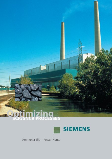
LDS 3000<br />
<strong>Siemens</strong> Laser Analytics provides<br />
gas analyzers – LDS 3000 – for<br />
process control applications based<br />
on tunable diode laser. Due to the<br />
early Swedish deNOx legislation we<br />
focused on ammonia analyzers in<br />
the late eighties <strong>and</strong> grew later into<br />
combustion control applications. Filter<br />
<strong>optimization</strong> <strong>and</strong> emission monitoring<br />
are also substantial parts of<br />
our core applications.<br />
Our fi rst commercial order came<br />
1992 <strong>and</strong> today we have more<br />
than 60 installations in Europe, USA<br />
<strong>and</strong> Japan.<br />
accumulated on fl y ash, collected in<br />
an ESP which operates at a temperature<br />
above the ABS melting point, or<br />
if the heaters in the bottom hoppers<br />
locally create a temperature above<br />
this melting point the ABS can give<br />
a sticky ash from the ESP hoppers<br />
which can be problematic to h<strong>and</strong>le.<br />
If the ash collector is of a fabric fi lter<br />
type the salt can cause other operational<br />
problems, e.g. increased pressure<br />
drop.<br />
Flue Gas Desulphurization<br />
plant, (FGD)<br />
If the plant is equipped with a fl ue<br />
gas desulphurization plant, FGD,<br />
parts of the ammonia slip will also<br />
be absorbed on dust <strong>and</strong> particles<br />
<strong>and</strong> powder products from that process<br />
<strong>and</strong> parts of it will be solved into<br />
the process water in wet scrubber<br />
processes for removal of SO 2 , HCl<br />
etc. is used.<br />
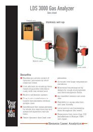
The Solution – Ammonia Slip Measurement using LDS 3000 from<br />
<strong>Siemens</strong> Laser Analytics AB – Laser Based Gas Analysis.<br />
Central unit – CU 3000<br />
LDS 3000<br />
Sensor pair<br />
CD 3002<br />
The central unit CU 3000<br />
All critical components are housed<br />
in the central unit <strong>and</strong> it can be<br />
placed several hundred meters away<br />
from the measurement point. The<br />
communication with the sensor is<br />
through optical fi bers.<br />
Sensor CD 3002<br />
The sensor consists of a pair mounted<br />
opposite of each other. An optical<br />
component (lens or window) is facing<br />
the process <strong>and</strong> protected with<br />
purging air or other gas. The sensor<br />
pair contains a minimum of electrical<br />
or optical components to improve<br />
reliability <strong>and</strong> availability.<br />
Related documents<br />
Additional documents can be downloaded<br />
from our web site at:<br />
http://www.siemens.se/sla<br />
Navigate to Service & Support <strong>and</strong><br />
Documentation<br />
1 Product Information<br />
2 LDS 3000 Overview<br />
3 LDS 3000 Basic Operation<br />
4 LDS 3000 Data Sheet<br />
5 Measurement Principle<br />
6 Dust Compensation<br />
Contact<br />
<strong>Siemens</strong> Laser Analytics (headquarters<br />
in Göteborg, Sweden)<br />
Marketing Director<br />
Jan Grimbr<strong>and</strong>t<br />
jan.grimbr<strong>and</strong>t@siemens.com<br />
Marketing Assistant<br />
Michaela Hermansson<br />
michaela.hermansson@siemens.com<br />
Phone: +46 (0)31 50 68 50<br />
web: http://www.siemens.se/sla
Your local representative<br />
Better control of your process<br />
<strong>Siemens</strong> is a network encom- encom-<br />
passing more than 450,000<br />
people in 190 countries. We<br />
take pride in possessing in-<br />
depth knowledge of customers’<br />
requirements <strong>and</strong> the expertise<br />
to create innovative solutions<br />
in electrical engineering <strong>and</strong><br />
electronics.<br />
<strong>Siemens</strong> Laser Analytics AB<br />
Box 8910<br />
402 73 Göteborg<br />
Phone: +46 31 50 68 50<br />
fax: +46 31 22 21 19<br />
mail: info@lds3000.com<br />
web: http://www.siemens.se/sla