Monorail Guidance Systems
Monorail Guidance Systems
Monorail Guidance Systems

Create successful ePaper yourself
Turn your PDF publications into a flip-book with our unique Google optimized e-Paper software.
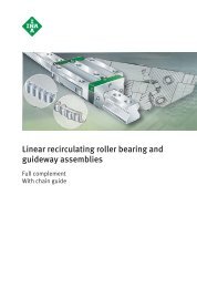
<strong>Monorail</strong> <strong>Guidance</strong> <strong>Systems</strong><br />
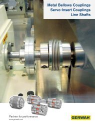
Linear recirculating roller bearing<br />
and guideway assemblies<br />
Linear recirculating ball bearing<br />
and guideway assemblies<br />
Linear guidance systems<br />
with linear recirculating ball bearing units<br />
Accessories
All data have been prepared with a great deal<br />
of care and checked for their accuracy.<br />
However, no liability can be assumed for any<br />
incorrect or incomplete data. We reserve the<br />
right to make technical modifications.<br />
© Schaeffler KG · 2008, March<br />
Reproduction in whole or in part without our<br />
authorisation is prohibited.
High load capacity, rigid,<br />
flexible, cost-effective<br />
Accessories<br />
for any application<br />
Foreword<br />
The performance capacity and economic success of a design<br />
incorporating monorail guidance systems is essentially dependent<br />
on the components used. It is at this stage that the competitive<br />
technical superiority and subsequent acceptance in the market of<br />
the machine or installation is often decided. However, the bearing<br />
arrangement must be precisely matched to the application and<br />
achievable by the use of standard components.<br />
INA monorail guidance systems are compact linear guidance<br />
systems that are supplied complete as standard and have high<br />
rigidity and load carrying capacity. They can support forces from all<br />
directions – apart from the direction of motion – as well as moments<br />
about all axes and can be supplied in various accuracies and<br />
preload classes. As a result, they are also suitable for applications<br />
with high guidance and positioning requirements.<br />
In most series, the carriages and guideways can be used in any<br />
combination within the same accuracy class. This gives a<br />
high degree of design flexibility with simplified fitting and reduced<br />
stockholding costs for guidance systems.<br />
In order to reduce maintenance costs, the monorail guidance<br />
systems have a lubricant reservoir. As a result, they are<br />
maintenance-free for many applications.<br />
Range Catalogue PF 1 gives information on:<br />
■ linear recirculating roller bearing and guideway assemblies RUE<br />
■ six-row linear recirculating ball bearing<br />
and guideway assemblies KUSE<br />
■ four-row linear recirculating ball bearing<br />
and guideway assemblies KUVE<br />
■ two-row linear recirculating ball bearing<br />
and guideway assemblies KUE<br />
■ linear guidance systems with linear recirculating<br />
ball bearing units KUVS.<br />
It also describes the relevant principles of rolling bearing technology<br />
for the design and lubrication of bearing arrangements based on<br />
these guidance systems.<br />
The comprehensive standard range can be further optimised by<br />
means of a range of accessories precisely matched to various<br />
application requirements.<br />
Replacement for ... The new catalogue replaces Schaeffler Group Catalogue 605.<br />
The data in the catalogue represent the current level of technology<br />
and manufacture as of March 2007. They reflect not only progress<br />
in rolling bearing technology but also the experience gathered in<br />
practical use.<br />
Data in earlier catalogues as well as in Product and<br />
Market Information publications that do not correspond to the data<br />
in this catalogue are therefore invalid.
Safety guidelines and symbols<br />
High product safety Our products correspond to the current level of research and<br />
technology. If the bearing arrangement is designed correctly,<br />
the products are handled and fitted correctly and as agreed and<br />
if they are maintained as instructed, they do not give rise to any<br />
direct hazards.<br />
Follow instructions This publication describes standard products. Since these are used<br />
in numerous applications, we cannot make a judgement as to<br />
whether any malfunctions will cause harm to persons or property.<br />
It is always and fundamentally the responsibility of the designer and<br />
user to ensure that all specifications are observed and that all<br />
necessary safety information is communicated to the end user.<br />
This applies in particular to applications in which product failure<br />
and malfunction may constitute a hazard to human beings.<br />
Definition of<br />
guidelines and symbols<br />
Caution<br />
The warning and hazard symbols are defined along the lines of<br />
ANSI Z535.6–2006.<br />
The meaning of the guidelines and symbols is as follows.<br />
If they are not observed, minor or slight injury will occur.<br />
Attention! If they are not observed, damage or malfunctions in the product or<br />
the adjacent construction will occur.<br />
Note! There follows additional or more detailed information that must be<br />
observed.<br />
Numbers within a circle are item numbers.<br />
This symbol indicates the locating side.<br />
This symbol indicates the marked side.<br />
4 PF 1 Schaeffler Group Industrial
Contents<br />
Page<br />
Safety guidelines and symbols ................................................ 4<br />
Product index .......................................................................... 6<br />
Technical principles ................................................................ 16<br />
Product range<br />
Linear recirculating roller bearing<br />
and guideway assemblies................................................... 89<br />
Six-row linear recirculating ball bearing<br />
and guideway assemblies................................................... 173<br />
Four-row linear recirculating ball bearing<br />
and guideway assemblies................................................... 225<br />
Two-row linear recirculating ball bearing<br />
and guideway assemblies................................................... 405<br />
Linear guidance systems with linear recirculating<br />
ball bearing units................................................................ 444<br />
Addresses ............................................................................... 464<br />
Schaeffler Group Industrial PF 1 5
Product index<br />
Page<br />
ABE End wiper unit for six-row linear recirculating ball bearing<br />
and guideway assembly ....................................................... 207<br />
ABE End wiper unit for two-row linear ball bearing<br />
and guideway assembly ....................................................... 434<br />
ADB Covering strip for guideways, adhesive bonded,<br />
for linear recirculating roller bearing<br />
and guideway assembly ....................................................... 131<br />
ADB Covering strip for guideways, adhesive bonded,<br />
for six-row linear recirculating ball bearing<br />
and guideway assembly ....................................................... 206<br />
ADB Covering strip for guideways, adhesive bonded,<br />
for four-row linear recirculating ball bearing<br />
and guideway assembly ....................................................... 340<br />
ADB..-K Covering strip for guideways, adhesive bonded,<br />
for linear recirculating roller bearing<br />
and guideway assembly ....................................................... 131<br />
ADB..-K Covering strip for guideways, adhesive bonded,<br />
for six-row linear recirculating ball bearing<br />
and guideway assembly ....................................................... 206<br />
ADB..-K Covering strip for guideways, adhesive bonded,<br />
for four-row linear recirculating ball bearing<br />
and guideway assembly ....................................................... 340<br />
APLE Sheet steel wiper for two-row linear recirculating ball bearing<br />
and guideway assembly ....................................................... 434<br />
APLSE Sheet steel wiper for six-row linear recirculating ball bearing<br />
and guideway assembly ....................................................... 207<br />
BKE.TKSD Braking and clamping element for six-row linear recirculating<br />
ball bearing and guideway assembly .................................... 206<br />
BKE.TKVD Braking and clamping element for four-row linear recirculating<br />
ball bearing and guideway assembly .................................... 341<br />
BKE.TSX Braking and clamping element for linear recirculating<br />
roller bearing and guideway assembly .................................. 132<br />
BPLE Lubrication adapter plate for two-row linear recirculating<br />
ball bearing and guideway assembly .................................... 434<br />
BPLSE Lubrication adapter plate for six-row linear recirculating<br />
ball bearing and guideway assembly .................................... 207<br />
ERVS Mounting device for covering strip, clip fit,<br />
for six-row linear recirculating ball bearing<br />
and guideway assembly ....................................................... 206<br />
ERVU Mounting device for covering strip, clip fit,<br />
for linear recirculating roller bearing<br />
and guideway assembly ....................................................... 131<br />
ERVV Mounting device for covering strip, clip fit,<br />
for four-row linear recirculating ball bearing<br />
and guideway assembly ....................................................... 340<br />
6 PF 1 Schaeffler Group Industrial
Page<br />
KA..-M Brass closing plug for linear recirculating roller bearing<br />
and guideway assembly ....................................................... 131<br />
KA..-M Brass closing plug for six-row linear recirculating ball bearing<br />
and guideway assembly ....................................................... 206<br />
KA..-M Brass closing plug for four-row linear recirculating ball bearing<br />
and guideway assembly ....................................................... 340<br />
KA..-M Brass closing plug for two-row linear recirculating ball bearing<br />
and guideway assembly ....................................................... 434<br />
KA..-MSA Brass closing plug,<br />
with plastic clinch ring for linear recirculating roller bearing<br />
and guideway assembly ....................................................... 131<br />
KA..-MSA Brass closing plug,<br />
with plastic clinch ring for four-row linear recirculating<br />
ball bearing and guideway assembly .................................... 340<br />
KA..-TN Plastic closing plug for linear guidance systems with linear<br />
recirculating ball bearing units ............................................. 446<br />
KA..-TN Plastic closing plug for six-row linear recirculating ball bearing<br />
and guideway assembly ....................................................... 179<br />
KA..-TN Plastic closing plug for linear recirculating roller bearing<br />
and guideway assembly ....................................................... 96<br />
KA..-TN Plastic closing plug for two-row linear recirculating ball bearing<br />
and guideway assembly ....................................................... 410<br />
KA..-TN/A Plastic closing plug, with clinch ring ........................................ 234<br />
KIT KIT system, for sealing elements,<br />
for linear recirculating roller bearing<br />
and guideway assembly ....................................................... 132<br />
KIT KIT system, for lubrication elements,<br />
for linear recirculating roller bearing<br />
and guideway assembly ....................................................... 132<br />
KIT KIT system, for sealing elements,<br />
for four-row linear recirculating ball bearing<br />
and guideway assembly ....................................................... 341<br />
KIT KIT system, for lubrication elements,<br />
for four-row linear recirculating ball bearing<br />
and guideway assembly ....................................................... 341<br />
Schaeffler Group Industrial PF 1 7
Product index<br />
Page<br />
KUE Two-row ball linear recirculating bearing<br />
and guideway assembly....................................................... 410<br />
KUE..-H Two-row ball linear recirculating bearing<br />
and guideway assembly, high design.................................... 410<br />
KUSE Six-row linear recirculating ball bearing<br />
and guideway assembly ....................................................... 178<br />
KUSE..-H Six-row linear recirculating ball bearing<br />
and guideway assembly, high design.................................... 178<br />
KUSE..-HL Six-row linear recirculating ball bearing<br />
and guideway assembly, high and long design ..................... 178<br />
KUSE..-L Six-row linear recirculating ball bearing<br />
and guideway assembly, long design.................................... 178<br />
KUVE..-B Four-row linear recirculating ball bearing<br />
and guideway assembly ....................................................... 231<br />
KUVE..-B-EC Four-row linear recirculating ball bearing<br />
and guideway assembly, short design .................................. 231<br />
KUVE..-B-ESC Four-row linear recirculating ball bearing<br />
and guideway assembly, narrow and short design ................ 231<br />
KUVE..-B-H Four-row linear recirculating ball bearing<br />
and guideway assembly, high design.................................... 231<br />
KUVE..-B-HL Four-row linear recirculating ball bearing<br />
and guideway assembly, high and long design ..................... 231<br />
KUVE..-B-L Four-row linear recirculating ball bearing<br />
and guideway assembly, long design.................................... 231<br />
KUVE..-B-N Four-row linear recirculating ball bearing<br />
and guideway assembly, low design ..................................... 231<br />
KUVE..-B-NL Four-row linear recirculating ball bearing<br />
and guideway assembly, low and long design....................... 231<br />
KUVE..-B-S Four-row linear recirculating ball bearing<br />
and guideway assembly, narrow and short design ................ 231<br />
KUVE..-B-SL Four-row linear recirculating ball bearing<br />
and guideway assembly, narrow and long design ................. 231<br />
KUVE..-B-SN Four-row linear recirculating ball bearing<br />
and guideway assembly, narrow and low design................... 231<br />
KUVE..-B-SNL Four-row linear recirculating ball bearing<br />
and guideway assembly, narrow, low and long design .......... 231<br />
8 PF 1 Schaeffler Group Industrial
Page<br />
KUVE..-B-KT Four-row linear recirculating ball bearing<br />
and guideway assembly, with Quad-Spacers, low noise ....... 232<br />
KUVE..-B-KT-H Four-row linear recirculating ball bearing<br />
and guideway assembly, with Quad-Spacers,<br />
low noise, high design.......................................................... 232<br />
KUVE..-B-KT-HL Four-row linear recirculating ball bearing<br />
and guideway assembly, with Quad-Spacers,<br />
low noise, high and long design ........................................... 232<br />
KUVE..-B-KT-L Four-row linear recirculating ball bearing<br />
and guideway assembly, with Quad-Spacers,<br />
low noise, long design.......................................................... 232<br />
KUVE..-B-KT-S Four-row linear recirculating ball bearing<br />
and guideway assembly, with Quad-Spacers,<br />
low noise, narrow design...................................................... 232<br />
KUVE..-B-KT-SL Four-row linear recirculating ball bearing<br />
and guideway assembly, with Quad-Spacers,<br />
low noise, narrow and long design ....................................... 232<br />
KUVE..-W Four-row linear recirculating ball bearing<br />
and guideway assembly, wide design................................... 231<br />
KUVE..-WL Four-row linear recirculating ball bearing<br />
and guideway assembly, wide and long design .................... 231<br />
KUVS Linear recirculating ball bearing unit........................................ 446<br />
KWE Carriage for two-row linear recirculating ball bearing<br />
and guideway assembly ....................................................... 410<br />
KWE..-H Carriage for two-row linear recirculating ball bearing<br />
and guideway assembly,high design .................................... 410<br />
KWSE Carriage for six-row linear recirculating ball bearing<br />
and guideway assembly ....................................................... 178<br />
KWSE..-H Carriage for six-row linear recirculating ball bearing<br />
and guideway assembly, high design ................................... 178<br />
KWSE..-HL Carriage for six-row linear recirculating ball bearing<br />
and guideway assembly, high and long design..................... 178<br />
KWSE..-L Carriage for six-row linear recirculating ball bearing<br />
and guideway assembly, long design ................................... 178<br />
KWVE..-B Carriage for four-row linear recirculating ball bearing<br />
and guideway assembly ....................................................... 231<br />
KWVE..-B-EC Carriage for four-row linear recirculating ball bearing<br />
and guideway assembly, short design .................................. 231<br />
KWVE..-B-ESC Carriage for four-row linear recirculating ball bearing<br />
and guideway assembly, narrow and short design................ 231<br />
KWVE..-B-H Carriage for four-row linear recirculating ball bearing<br />
and guideway assembly, high design ................................... 231<br />
KWVE..-B-HL Carriage for four-row linear recirculating ball bearing<br />
and guideway assembly, high and long design..................... 231<br />
KWVE..-B-L Carriage for four-row linear recirculating ball bearing<br />
and guideway assembly, long design ................................... 231<br />
Schaeffler Group Industrial PF 1 9
Product index<br />
Page<br />
KWVE..-B-N Carriage for four-row linear recirculating ball bearing<br />
and guideway assembly, low design ..................................... 231<br />
KWVE..-B-NL Carriage for four-row linear recirculating ball bearing<br />
and guideway assembly, low and long design....................... 231<br />
KWVE..-B-S Carriage for four-row linear recirculating ball bearing<br />
and guideway assembly, narrow design................................ 231<br />
KWVE..-B-SN Carriage for four-row linear recirculating ball bearing<br />
and guideway assembly, narrow and low design................... 231<br />
KWVE..-B-SL Carriage for four-row linear recirculating ball bearing<br />
and guideway assembly, narrow and long design ................. 231<br />
KWVE..-B-SNL Carriage for four-row linear recirculating ball bearing<br />
and guideway assembly, narrow, low and long design .......... 231<br />
KWVE..-W Carriage for four-row linear recirculating ball bearing<br />
and guideway assembly, wide design ................................... 231<br />
KWVE..-WL Carriage for four-row linear recirculating ball bearing<br />
and guideway assembly, wide and long design..................... 231<br />
KWVE..-B-KT Carriage for four-row linear recirculating ball bearing<br />
and guideway assembly, with Quad-Spacers, low noise........ 232<br />
KWVE..-B-KT-H Carriage for four-row linear recirculating ball bearing<br />
and guideway assembly, with Quad-Spacers, low noise,<br />
high design .......................................................................... 232<br />
KWVE..-B-KT-HL Carriage for four-row linear recirculating ball bearing<br />
and guideway assembly, with Quad-Spacers, low noise,<br />
high and long design ............................................................ 232<br />
KWVE..-B-KT-L Carriage for four-row linear recirculating ball bearing<br />
and guideway assembly, with Quad-Spacers, low noise,<br />
long design........................................................................... 232<br />
KWVE..-B-KT-S Carriage for four-row linear recirculating ball bearing<br />
and guideway assembly, with Quad-Spacers, low noise,<br />
narrow design....................................................................... 232<br />
KWVE..-B-KT-SL Carriage for four-row linear recirculating ball bearing<br />
and guideway assembly, with Quad-Spacers, low noise,<br />
narrow and long design ........................................................ 232<br />
KWVK..-AL Carriage with linear recirculating ball bearing units.................. 446<br />
10 PF 1 Schaeffler Group Industrial
Page<br />
LMSD Integrated absolute digital measuring system<br />
for four-row linear recirculating ball bearing<br />
and guideway assembly ....................................................... 324<br />
LMST Integrated incremental measuring system<br />
for four-row linear recirculating ball bearing<br />
and guideway assembly ....................................................... 324<br />
M-Satz Mounting set for linear recirculating roller bearing<br />
and guideway assembly RUE..-E ........................................... 96<br />
MA10/4 Positional display for measuring system.................................. 324<br />
MKD Dummy guideway for two-row ball linear recirculating<br />
bearing and guideway assembly........................................... 410<br />
MKSD Dummy guideway for six-row linear recirculating<br />
ball bearing and guideway assembly .................................... 179<br />
MKVD Dummy guideway for four-row linear recirculating<br />
ball bearing and guideway assembly .................................... 234<br />
MSX..-E Dummy guideway for linear recirculating roller bearing<br />
and guideway assembly ....................................................... 96<br />
MVH.TSX..-D-A Hydraulic fitting device for closing plugs ................................. 131<br />
RUDS..-D Damping carriage for linear recirculating roller bearing<br />
and guideway assembly ....................................................... 132<br />
RUE25-D Linear recirculating roller bearing and guideway assembly,<br />
full complement ................................................................... 94<br />
RUE..-E Linear recirculating roller bearing and guideway assembly,<br />
full complement ................................................................... 94<br />
RUE..-E-L Linear recirculating roller bearing and guideway assembly,<br />
full complement, long design ............................................... 94<br />
RUE..-E-H Linear recirculating roller bearing and guideway assembly,<br />
full complement, high design ............................................... 94<br />
RUE..-E-HL Linear recirculating roller bearing and guideway assembly,<br />
full complement, high and long design................................. 94<br />
RUE..-E-KT-L Linear recirculating roller bearing and guideway assembly,<br />
with chain guidance system, long design.............................. 95<br />
RUE..-E-KT-HL Linear recirculating roller bearing and guideway assembly,<br />
with chain guidance system, high and long design ............... 95<br />
Schaeffler Group Industrial PF 1 11
Product index<br />
Page<br />
RWU25-D Carriage for linear recirculating roller bearing<br />
and guideway assembly, full complement ............................ 94<br />
RWU..-E Carriage for linear recirculating roller bearing<br />
and guideway assembly, full complement ............................ 94<br />
RWU..-E-L Carriage for linear recirculating roller bearing<br />
and guideway assembly, full complement, long design......... 94<br />
RWU..-E-H Carriage for linear recirculating roller bearing<br />
and guideway assembly, full complement, high design......... 94<br />
RWU..-E-HL Carriage for linear recirculating roller bearing<br />
and guideway assembly, full complement,<br />
high and long design ............................................................ 94<br />
RWU..-E-KT-L Carriage for linear recirculating roller bearing<br />
and guideway assembly, with chain guidance system,<br />
long design........................................................................... 95<br />
RWU..-E-KT-HL Carriage for linear recirculating roller bearing<br />
and guideway assembly, with chain guidance system,<br />
high and long design ............................................................ 95<br />
RUKS..-D-A Clamping element for linear recirculating roller bearing<br />
and guideway assembly ....................................................... 132<br />
SMAD.KFE Lubrication adapter for grease for six-row linear recirculating<br />
ball bearing and guideway assembly .................................... 207<br />
SMAD.KOE Lubrication adapter for oil for six-row linear recirculating<br />
ball bearing and guideway assembly .................................... 207<br />
SMAD.KFE Lubrication adapter for grease for two-row linear recirculating<br />
ball bearing and guideway assembly .................................... 434<br />
SMAD.KOE Lubrication adapter for oil for two-row linear recirculating<br />
ball bearing and guideway assembly .................................... 434<br />
SPPL Clamping strip ......................................................................... 340<br />
SPPR Clamping lug ........................................................................... 340<br />
12 PF 1 Schaeffler Group Industrial
Page<br />
TKD Guideway for two-row linear recirculating ball bearing<br />
and guideway assembly ....................................................... 410<br />
TKSD Guideway for six-row linear recirculating ball bearing<br />
and guideway assembly ....................................................... 179<br />
TKSD..-ADB Guideway for six-row linear recirculating ball bearing<br />
and guideway assembly with covering strip,<br />
adhesive bonded ................................................................. 179<br />
TKSD..-ADB+K Guideway for six-row linear recirculating ball bearing<br />
and guideway assembly with covering strip, clip fit............... 179<br />
TKSD..-U Guideway for six-row linear recirculating ball bearing<br />
and guideway assembly, for mounting from below ............... 179<br />
TKVD Guideway for linear guidance systems with linear recirculating<br />
ball bearing units ................................................................. 446<br />
TKVD Guideway for four-row linear recirculating ball bearing<br />
and guideway assembly ....................................................... 233<br />
TKVD..-ADB Guideway for four-row linear recirculating ball bearing<br />
and guideway assembly, with covering strip,<br />
adhesive bonded ................................................................. 233<br />
TKVD..-ADB+K Guideway for four-row linear recirculating ball bearing<br />
and guideway assembly, with covering strip, clip fit.............. 233<br />
TKVD..-K Guideway for four-row linear recirculating ball bearing<br />
and guideway assembly, for clamping .................................. 233<br />
TKVD..-U Guideway for six-row linear recirculating ball bearing<br />
and guideway assembly, for mounting from below ............... 233<br />
TKVD..-W Wide guideway for four-row linear recirculating ball bearing<br />
and guideway assembly ....................................................... 233<br />
TKVD..-ZHP Guideway with tooth set on underside<br />
for four-row linear recirculating ball bearing<br />
and guideway assembly ....................................................... 233<br />
TKVD..-ZHST+SVS Guideway with lateral tooth set for four-row linear<br />
recirculating ball bearing and guideway assembly ................ 233<br />
TSX..-D Guideway for linear recirculating roller bearing<br />
and guideway assembly RUE25-D......................................... 94<br />
TSX..-D-U Guideway for linear recirculating roller bearing<br />
and guideway assembly RUE25-D,<br />
for mounting from below ...................................................... 94<br />
TSX..-E Guideway for linear recirculating roller bearing<br />
and guideway assembly RUE..-E ........................................... 96<br />
TSX..-E-ADB Guideway for linear recirculating roller bearing<br />
and guideway assembly RUE..-E,<br />
with covering strip, adhesive bonded ................................... 96<br />
TSX..-E-ADB+K Guideway for linear recirculating roller bearing<br />
and guideway assembly RUE..-E,<br />
with covering strip, clip fit .................................................... 96<br />
TSX..-E-U Guideway for linear recirculating roller bearing<br />
and guideway assembly RUE..-E,<br />
for mounting from below ...................................................... 96<br />
Schaeffler Group Industrial PF 1 13
207 102<br />
206 051<br />
205 267<br />
204 048<br />
205 269
207 101<br />
206 050<br />
205 266<br />
204 047<br />
205 268<br />
Technical principles<br />
Linear recirculating roller bearing<br />
and guideway assemblies<br />
Six-row linear recirculating ball bearing<br />
and guideway assemblies<br />
Four-row linear recirculating<br />
ball bearing<br />
and guideway assemblies<br />
Two-row linear recirculating ball bearing<br />
and guideway assemblies<br />
Linear guidance systems with linear<br />
recirculating ball bearing units<br />
Appendix
x<br />
z<br />
y<br />
x y<br />
M 0x<br />
z<br />
C, C0<br />
x<br />
(C, C0)<br />
y<br />
M0z<br />
M 0y<br />
Technical principles<br />
Load carrying capacity and life<br />
INA calculation program<br />
Preload<br />
Friction<br />
Lubrication<br />
Special coatings<br />
Special materials<br />
Fitting variants<br />
Fitting<br />
z<br />
0<br />
0<br />
10<br />
20<br />
30<br />
40<br />
50<br />
5<br />
65<br />
60 RUE..-D-H, D-HL<br />
m F<br />
10<br />
15<br />
F<br />
F<br />
RUE..-D, D-L<br />
20<br />
25<br />
30<br />
kN<br />
25-D<br />
35<br />
25-D-H<br />
25-D-H-L<br />
25-D-L
Load carrying capacity<br />
and life<br />
Technical principles<br />
Schaeffler Group Industrial PF 1 17<br />
Page<br />
Load carrying capacity............................................................... 20<br />
Calculation of basic load ratings according to DIN................. 20<br />
Dynamic load carrying capacity and life..................................... 20<br />
Basic rating life ......................................................................... 21<br />
Equivalent load and speed ................................................... 21<br />
Operating life ............................................................................ 23<br />
Static load carrying capacity...................................................... 23<br />
Basic static load ratings and static moment ratings .............. 23<br />
Static load safety factor ........................................................ 24<br />
Strength of guidance systems............................................... 25<br />
INA calculation program BEARINX ® for precise design ....................................................... 26<br />
BEARINX ® linear module......................................................... 26<br />
Calculation program –<br />
example of input date for a design brief................................ 28<br />
example of the travel of a linear table ................................... 33<br />
Preload Influence of preload .................................................................. 36<br />
Preload and damping ........................................................... 36<br />
Friction Influencing factors..................................................................... 37<br />
Influence of grease on friction............................................... 37<br />
Influence of seals on friction................................................. 37
Technical principles<br />
18 PF 1 Schaeffler Group Industrial<br />
Page<br />
Lubrication Oil or grease lubrication ............................................................ 38<br />
Delivered condition, suitable lubricants ................................ 38<br />
Oil lubrication............................................................................ 39<br />
Compatibility ........................................................................ 39<br />
Miscibility ............................................................................. 39<br />
Lubricant quantities.............................................................. 40<br />
Grease lubrication ..................................................................... 44<br />
Flowable grease lubrication .................................................. 44<br />
Grease lubrication................................................................. 45<br />
Miscibility ............................................................................. 45<br />
Storage life ........................................................................... 46<br />
Initial grease quantity ........................................................... 46<br />
Calculation of lubrication interval.......................................... 48<br />
Relubrication interval............................................................ 51<br />
Relubrication of the guidance system.................................... 51<br />
Special coatings Types of coatings....................................................................... 52<br />
Advantages of thin film chromium plating ............................. 52<br />
Corrotect ® special coating .................................................... 53<br />
Protect A ............................................................................... 55<br />
Protect B ............................................................................... 57<br />
Special materials Materials for KUVE ..................................................................... 59<br />
Corrosion-resistant steel ....................................................... 59<br />
Amagnetic steel .................................................................... 60<br />
Metal end piece .................................................................... 61<br />
Ceramic rolling elements....................................................... 62<br />
Fitting variants Fitting work – influencing factors and assessment..................... 63<br />
Fitting work ........................................................................... 64<br />
Alignment elements .............................................................. 65<br />
Suspended arrangement of guidance system........................ 67
Schaeffler Group Industrial PF 1 19<br />
Page<br />
Fitting Fixing screws for carriages and guideways................................. 68<br />
Fitting of monorail guidance systems ........................................ 69<br />
Guidelines ............................................................................ 69<br />
Delivered condition .............................................................. 70<br />
Dismantling and fitting of carriages ...................................... 71<br />
Location of carriages............................................................. 71<br />
Location of guideways .......................................................... 72<br />
Fitting of closing plugs.......................................................... 73<br />
Fitting of brass closing plugs using fitting device .................. 74<br />
Fitting of two-piece plastic closing plugs............................... 76<br />
Fitting of adhesive bonded covering strip.............................. 77<br />
Fitting of clip fit covering strip............................................... 78<br />
Fitting of clamping element................................................... 80<br />
Fitting of damping carriage ................................................... 82<br />
Fitting example for a linear guidance system......................... 84<br />
Putting the guidance system into operation .......................... 87
Load carrying capacity and life<br />
The size of a monorail guidance system is determined by the<br />
demands made on its load carrying capacity, rating life and<br />
operational security.<br />
Load carrying capacity The load carrying capacity is described in terms of the<br />
basic dynamic load rating C, the basic static load rating C 0<br />
and the static moment ratings M 0x, M 0y and M 0z, Figure 1.<br />
Figure 1<br />
Load carrying capacity<br />
and load directions<br />
Calculation of<br />
basic load ratings<br />
according to DIN<br />
Differences between DIN<br />
and suppliers from the Far East<br />
Conversion of basic load ratings<br />
Linear recirculating ball bearing<br />
and guideway assemblies<br />
Linear recirculating roller bearing<br />
and guideway assemblies<br />
Dynamic load<br />
carrying capacity and life<br />
C, C 0<br />
M 0x<br />
x<br />
y<br />
The calculation of the basic dynamic and static load ratings given in<br />
the dimension tables is based on DIN 636-1 and 2.<br />
Suppliers from the Far East frequently calculate basic load ratings<br />
using a basic rating life based on a distance of only 50 km compared<br />
with 100 km to DIN.<br />
C50 = 1,26⋅C100<br />
C100 = 0,79⋅C50<br />
C50 = 1,23⋅C100<br />
C100 = 0,81⋅C50<br />
C100 N<br />
Basic dynamic load rating C for distance of 100 km –<br />
definition according to DIN 636<br />
C50 N<br />
Basic dynamic load rating C for distance of 50 km.<br />
The dynamic load carrying capacity is described in terms of the basic<br />
dynamic load rating and the basic rating life.<br />
The basic dynamic load rating is the load in N at which the guidance<br />
system achieves a distance of 100 km at a survival probability of<br />
90% (C 100).<br />
20 PF 1 Schaeffler Group Industrial<br />
z<br />
C, C 0<br />
x<br />
M 0z<br />
z<br />
y<br />
x y<br />
z<br />
M 0y<br />
207 096
Basic rating life The basic rating life L and L h is achieved by 90% of a sufficiently<br />
large group of apparently identical bearings before the first evidence<br />
of material fatigue occurs.<br />
p<br />
C<br />
L =<br />
P<br />
⎛ ⎞<br />
⎝<br />
⎜<br />
⎠<br />
⎟<br />
p<br />
C<br />
Lh<br />
= ⋅<br />
Hn ⋅ osc P<br />
⎛ 833 ⎞<br />
⎝<br />
⎜<br />
⎠<br />
⎟<br />
p<br />
C<br />
Lh<br />
= ⋅<br />
v P<br />
⎛ 1666 ⎞<br />
⎝<br />
⎜<br />
⎠<br />
⎟<br />
Attention! According to DIN 636-1, the equivalent dynamic load P should not<br />
exceed the value 0,5 · C.<br />
Equivalent load and speed The formulae for calculating the basic rating life assume that the<br />
load P and speed v are constant. Non-constant operating conditions<br />
can be taken into consideration by means of equivalent operating<br />
values. These have the same effect on the life as the loads occurring<br />
in practice.<br />
Equivalent dynamic load Where the load varies in steps, the equivalent dynamic load is<br />
calculated as follows:<br />
p p<br />
q v F q v F q v F<br />
P<br />
z z z<br />
q v q v q v<br />
p<br />
= p 1⋅ 1⋅ 1 + 2⋅ 2⋅ 2 + ... + ⋅ ⋅<br />
1⋅ 1+ 2⋅ 2+<br />
... + z⋅ z<br />
Equivalent dynamic speed Where the speed varies in steps, the equivalent dynamic speed is<br />
calculated as follows:<br />
q v q v q v<br />
v = 1⋅ 1+ 2⋅ 2+<br />
... + z⋅ z<br />
100<br />
Combined load If the direction of the load acting on an element does not coincide<br />
with one of the main load directions, an approximate value for the<br />
equivalent load is calculated as follows:<br />
P= Fy + Fz<br />
If an element is simultaneously subjected to a force F and a<br />
moment M, an approximate value for the equivalent dynamic load is<br />
calculated as follows:<br />
P F M C<br />
= + ⋅<br />
M<br />
0<br />
0<br />
Schaeffler Group Industrial PF 1 21
Load carrying capacity and life<br />
Symbols, units and definitions C N<br />
Basic dynamic load rating<br />
C0 N<br />
Basic static load rating in the direction of the force acting on the element<br />
F N<br />
Force acting on the element<br />
Fy Vertical component<br />
N<br />
Fz Horizontal component<br />
N<br />
H m<br />
Single stroke length for reciprocating motion<br />
L, Lh m, h<br />
Basic rating life in 100 km or in operating hours<br />
M Nm<br />
Moment acting on the element<br />
M0 Static moment rating<br />
Nm<br />
nosc min –1<br />
Number of return strokes per minute<br />
P N<br />
Equivalent dynamic load<br />
p<br />
Life exponent:<br />
–<br />
monorail guidance systems based on balls: p = 3<br />
monorail guidance systems based on rollers: p = 10 / 3<br />
qz %<br />
Duration as a proportion of the total operating time<br />
vz Variable speed<br />
m/min<br />
v m/min<br />
Equivalent dynamic speed.<br />
22 PF 1 Schaeffler Group Industrial
Operating life The operating life is defined as the life actually achieved by monorail<br />
guidance systems. It may differ significantly from the calculated life.<br />
The following influences can lead to premature failure through wear<br />
or fatigue:<br />
■ excess load due to misalignment as a result of temperature<br />
differences and manufacturing tolerances<br />
(elasticity of the adjacent construction)<br />
■ contamination of the guidance systems<br />
■ inadequate lubrication<br />
■ reciprocating motion with very small stroke lengths<br />
(false brinelling)<br />
■ vibration while stationary (false brinelling)<br />
■ overloading of the guidance system (even for short periods)<br />
■ plastic deformation.<br />
Static load carrying capacity The static load carrying capacity of the monorail guidance system is<br />
limited by:<br />
■ the permissible load on the monorail guidance system<br />
■ the load carrying capacity of the raceway<br />
■ the permissible load on the screw connections<br />
■ the permissible load on the adjacent construction.<br />
Attention! For design purposes, the static load safety factor S 0 required for the<br />
application must be observed, see tables starting page 24.<br />
Basic static load ratings<br />
and moment ratings<br />
The basic static load ratings and static moment ratings are those<br />
loads under which the raceways and rolling elements undergo a<br />
permanent overall deformation corresponding to 1 / 10 000 of the<br />
rolling element diameter.<br />
Schaeffler Group Industrial PF 1 23
Load carrying capacity and life<br />
Static load safety factor The static load safety factor S 0 is the security against permanent<br />
deformation at the rolling contact:<br />
Application-oriented static load<br />
safety factor<br />
Application in machine tools<br />
C<br />
S0<br />
= 0<br />
P0<br />
S<br />
M<br />
0 = 0<br />
M<br />
S0 –<br />
Static load safety factor<br />
C0 N<br />
Basic static load rating in the load direction (for KUSE: C0I, C0II, C0III) according to dimension tables<br />
P0 N<br />
Equivalent static bearing load in load direction<br />
M0 Nm<br />
Basic static moment rating in load direction (M0x, M0y, M0z) according to dimension tables<br />
M Nm<br />
Equivalent static moment in load direction<br />
P N<br />
Equivalent dynamic load.<br />
The equivalent static bearing load is determined in approximate<br />
terms from the maximum loads:<br />
P F<br />
0 = max<br />
M M<br />
0 = max<br />
Attention! Static load safety factor S 0 for design of linear guidance systems,<br />
see tables starting page 24.<br />
For the design of linear guidance systems, the static load safety<br />
factor S 0 according to the following tables must be taken into<br />
consideration.<br />
Precondition S0 Critical case<br />
8 to 12<br />
■ High dynamic loading with one axis stationary<br />
■ Severe contamination<br />
■ Actual load parameters are not defined<br />
■ Catalogue specifications for accuracy of adjacent<br />
construction are not observed<br />
Normal case<br />
■ Not all load parameters are completely known<br />
or:<br />
■ Cutting forces are estimated from the performance data<br />
of the machine<br />
24 PF 1 Schaeffler Group Industrial<br />
5 to 8<br />
■ All load parameters are known 4 to 5<br />
■ All load parameters are known<br />
(and definitely correspond to reality)<br />
3 to 4
Application<br />
in general usage with<br />
overhead arrangement 1)<br />
Application in general usage<br />
Precondition S0 ■ Not all load parameters are known<br />
and fewer than 4 carriages support a coherent weight<br />
20<br />
■ Not all load parameters are known<br />
and at least 4 carriages support a coherent weight<br />
or:<br />
■ All load parameters are known and fewer than 4 carriages<br />
support a coherent weight<br />
■ All load parameters are known<br />
and at least 4 carriages support a coherent weight<br />
8 to 12<br />
1) If the guidance system is in a suspended arrangement, a drop guard<br />
is recommended, see page 67.<br />
Precondition S0 ■ Predominantly oscillating load with stationary<br />
guidance system<br />
20<br />
■ All load parameters are completely known<br />
and catalogue specifications for accuracy of the adjacent<br />
construction accuracy are observed, with smooth<br />
and vibration-free running<br />
Strength If the fixing screw threads are of a sufficient size, monorail<br />
of guidance systems guidance systems can be subjected to loads up to the static load<br />
carrying capacity C0 and M0 according to the dimension tables.<br />
Attention! The load must be transmitted via locating surfaces.<br />
Schaeffler Group Industrial PF 1 25<br />
5 to 8<br />
3 to 4
BEARINX ®<br />
for precise design<br />
INA calculation program<br />
The calculation on pages 20 to 23 is used for the preliminary<br />
selection of monorail guidance systems. They allow an approximate<br />
calculation of the equivalent static and dynamic bearing loads.<br />
In order to achieve precise design of linear guidance elements in<br />
relation to basic rating life and static load safety factor, it is<br />
necessary to calculate the bearing load in a statically indeterminate<br />
system and the internal load distribution of the linear guidance<br />
elements (Loading of individual rolling elements, Figure 1).<br />
This requires a complex calculation process.<br />
For this reason, INA developed the rolling bearing analysis program<br />
BEARINX ® which can be used to calculate linear and rotary bearings<br />
as a part of the complete system (e.g. machine tool, automotive<br />
gearbox, etc.) and thereby ensure reliable designs.<br />
Figure 1<br />
Internal load distribution under<br />
combined load 126 745a<br />
BEARINX ® linear module The linear module of BEARINX ® can be used to calculate linear<br />
guidance elements in multi-axis systems (e.g. machine tools) under<br />
any load combination down to the level of the rolling element<br />
contact. The integral analysis method can be used to investigate the<br />
influence of nearly all parameters of the complete system on<br />
relevant results.<br />
26 PF 1 Schaeffler Group Industrial
Taking account of<br />
elasticities in the system<br />
This sophisticated calculation model takes account of all the<br />
elasticities in the system, ranging from the rigidity of the<br />
saddle plate and guideways through to the non-linear deflection<br />
behaviour of the rolling elements.<br />
In order to determine even more precisely the pressure between the<br />
rolling elements and raceway in linear recirculating roller bearing<br />
and guideway assemblies, the end profiling of the rolling elements<br />
is also taken into consideration. The adjacent construction is<br />
assumed to be rigid in the first instance but can, if necessary,<br />
be modelled on an elastic basis by means of reduced rigidity<br />
matrices (e.g. from FE calculation).<br />
Very precise results This model gives significantly more precise results than calculation<br />
programs that only take account of elasticity in rolling contact.<br />
This means an increased level of security in the design.<br />
BEARINX ® allows the calculation of systems with any number of:<br />
travel axes, linear guidance elements and linear drives,<br />
load situations, loads and masses.<br />
The results provided by BEARINX ® include the static load safety<br />
factor, the basic rating life and the displacements that arise from the<br />
elasticity of the bearing arrangement.<br />
Calculation using BEARINX ® is available as a service.<br />
Linear BEARINX ® online The linear calculation program BEARINX ® online assists in the<br />
calculation and design of the linear guidance system, Figure 2;<br />
for information and registration, please visit: www.schaeffler.com.<br />
A fee will be charged for usage.<br />
Figure 2<br />
Example page<br />
from the online program 150 231<br />
Schaeffler Group Industrial PF 1 27
Calculation program –<br />
example of input data for<br />
a design brief<br />
Step 1<br />
Define the components<br />
Motor<br />
Headstock<br />
Base plate<br />
Linear guidance elements<br />
Drive<br />
Figure 3<br />
Defining the components<br />
INA calculation program<br />
The input data for the calculation program should be compiled from<br />
the design brief (with clearly dimensioned drawings or diagrams in<br />
at least two views). Here is a step-by-step guide based on a simple<br />
example to show the dimensioning process.<br />
The relevant factors for calculation, apart from the linear guidance<br />
elements and the drive system for the table, are those components<br />
that induce loads on the linear guidance elements (the inherent<br />
mass of the components or their inertia forces), Figure 3.<br />
1<br />
2 1<br />
2<br />
4 5 4<br />
5<br />
3 4<br />
28 PF 1 Schaeffler Group Industrial<br />
4<br />
173 406a
Step 2<br />
Define the table co-ordinate system<br />
Figure 4<br />
Defining the<br />
table co-ordinate system<br />
The table co-ordinate system is a Cartesian, right hand co-ordinate<br />
system.<br />
The directions in the table co-ordinate system are defined as<br />
follows, Figure 4:<br />
■ X axis: travel direction of the table<br />
■ Y axis: main load direction on the system (direction of weight)<br />
■ Z axis: derived from the right hand rule (lateral direction).<br />
The (translational) position of the table co-ordinate system is freely<br />
selectable. It is recommended that this should be located centrally<br />
between the carriages for directions X and Y.<br />
z x x<br />
z<br />
= =<br />
y y<br />
= =<br />
Schaeffler Group Industrial PF 1 29<br />
173 407a
Step 3<br />
Define the linear guidance<br />
elements<br />
Figure 5<br />
Defining the position of the linear<br />
guidance elements<br />
Step 4<br />
Define the position of the drives<br />
Figure 6<br />
Defining the position of the drives<br />
INA calculation program<br />
The translational position of the linear guidance elements is stated<br />
in relation to the table co-ordinate system. In order to determine the<br />
torsion angle of the linear guidance elements, their co-ordinate<br />
system is rotated about the X axis into the table co-ordinate system,<br />
Figure 5.<br />
z x x<br />
z<br />
L z = 250 L z = –250<br />
L x= 300 L x=<br />
–300<br />
The translational position of the drives (support function in the<br />
traverse direction) is stated in relation to the table co-ordinate<br />
system as Y and Z co-ordinates, Figure 6.<br />
LA z = –50<br />
y y<br />
30 PF 1 Schaeffler Group Industrial<br />
y<br />
L = 200<br />
y<br />
z<br />
–90°<br />
x z<br />
LA = 130<br />
y<br />
z x x<br />
z<br />
y y<br />
y<br />
x<br />
173 408a<br />
173 409a
Step 5<br />
Define the centres of gravity<br />
of the components<br />
Mass of motor<br />
Mass of headstock<br />
Mass of base plate<br />
Figure 7<br />
Defining the centres of gravity<br />
of the components<br />
Step 6<br />
Define the external loads<br />
Figure 8<br />
Defining the external loads<br />
The mass of the components is concentrated at a mass point at its<br />
centre.<br />
The translational position of the centres is again stated in relation to<br />
the table co-ordinate system, Figure 7.<br />
L yg = 60<br />
L ym = –320<br />
m = 60 kg<br />
m = 200 kg<br />
1 L zs = –260<br />
2<br />
L zm=<br />
80<br />
L zg = –100<br />
m = 170 kg<br />
3<br />
External loads such as machining forces on the linear table,<br />
are stated in relation to the table co-ordinate system.<br />
The following must be stated, Figure 8:<br />
■ in which of the defined load cases the load acts on the table<br />
co-ordinate system<br />
■ the position of its loading point<br />
■ the force and moment components.<br />
Schaeffler Group Industrial PF 1 31<br />
L ys = –300<br />
z x<br />
L xm = 170<br />
x<br />
z<br />
L zF<br />
= –260<br />
y y<br />
M x = 720 Nm<br />
L xg = 0<br />
z x x<br />
z<br />
y y<br />
x<br />
F x = 24 kN<br />
L xs = 80<br />
L F = –520<br />
x<br />
F y = 24 kN<br />
173 410a<br />
F z = 20 kN<br />
L yF<br />
= –270<br />
173 411a
Step 7<br />
Define the duty cycle<br />
to = load cases<br />
Figure 9<br />
Defining the duty cycle<br />
Travel<br />
Velocity<br />
Acceleration<br />
INA calculation program<br />
In order to depict the working cycle of the machine, a duty cycle must<br />
be described. This is composed of the motion parameters of the<br />
machine and their loading due to external loads (e.g. machining<br />
forces).<br />
On the basis of a speed/time diagram, the working cycle should be<br />
subdivided logically into individual load cases, Figure 9, to .<br />
With the aid of the basic motion formulae for uniform motion<br />
(v = const.) or uniform acceleration (a = const.) as appropriate,<br />
the missing values (travel, acceleration) can then be determined.<br />
v (m/s)<br />
0 0<br />
t (s)<br />
1 2 3<br />
⎛ v+ v<br />
st ()= s + 0 ⎞<br />
0 ⋅t<br />
⎝<br />
⎜<br />
2 ⎠<br />
⎟<br />
vt ()= v0+ at ⋅<br />
at<br />
v<br />
t<br />
()= <br />
32 PF 1 Schaeffler Group Industrial<br />
4<br />
5 6 7 8<br />
173 412a
Example of the travel<br />
of a linear table<br />
The following simplified example describes the travel of a linear<br />
table.<br />
The circled numbers to describe the load cases in Figure 9,<br />
page 32.<br />
Complex travel cases can in certain circumstances be usefully<br />
reduced by combination. Please consult the Schaeffler Group<br />
engineering service on this matter.<br />
Rapid traverse to<br />
machining position<br />
Acceleration In t 1 (0,05 s) to v 1 (0,5 m/s), Figure 9, page 32, .<br />
at<br />
v<br />
t<br />
()= <br />
05<br />
2<br />
a1m s<br />
005 10<br />
,<br />
= = /<br />
,<br />
v t<br />
s 1⋅1 1 =<br />
2<br />
05 , ⋅005<br />
,<br />
s1= = 0, 0125m= 12, 5mm<br />
2<br />
Deceleration In t 2 (0,045 s) to v 2 (0,05 m/s), Figure 9, page 32, .<br />
v v<br />
a 2−1 2 =<br />
t2<br />
005 , − 05 ,<br />
2<br />
a2= =−10<br />
m/ s<br />
0, 045<br />
v v<br />
s s 2+ 2 = 1<br />
1+<br />
⋅t<br />
2<br />
2<br />
005 , + 05 ,<br />
s2= 0, 0125+ ⋅ 0, 045 = 0, 0249m= 24, 9mm<br />
2<br />
ti s<br />
Duration of time interval i<br />
si mm<br />
Travel position at end of interval i<br />
vi m/s<br />
Velocity at end of interval i<br />
ai m/s<br />
Acceleration during interval i<br />
Schaeffler Group Industrial PF 1 33
INA calculation program<br />
Machining<br />
Constant velocity v 3 (0,05 m/s) for t 3 (1,105 s);<br />
additional effect of machining force, Figure 9, page 32, .<br />
2<br />
a3= 0 m/ s<br />
v3+ v2<br />
s3 = s2+<br />
⋅t<br />
3<br />
2<br />
Machining force Position:<br />
■ x = –520 mm<br />
■ y=–270mm<br />
■ z = –260 mm.<br />
Value:<br />
■ M x = 720 Nm<br />
■ F x =24Nm<br />
■ M y =24Nm<br />
■ F z =20Nm.<br />
005 , + 005 ,<br />
s3= 0, 0249 +<br />
⋅ 1, 105 = 0, 0801m= 80, 1mm<br />
2<br />
Deceleration In t 4 (0,0025 s) to v 4 (0 m/s), Figure 9, page 32, .<br />
v4−v3 a4<br />
=<br />
t 4<br />
00 , − 005 ,<br />
2<br />
a4= =−20<br />
m/ s<br />
0, 0025<br />
v4+ v3<br />
s4 = s3+<br />
⋅t<br />
4<br />
2<br />
00 , + 005 ,<br />
s4= 0, 0801+ ⋅ 0, 0025 = 0, 0802m= 80, 2mm<br />
2<br />
34 PF 1 Schaeffler Group Industrial
Rapid traverse back to<br />
original position<br />
Acceleration In t 5 (0,025) to v 5 (–0,5 m/s);<br />
opposing direction, Figure 9, page 32, .<br />
v5−v4 a5<br />
=<br />
t5<br />
05 00<br />
2<br />
a5= 20 m s<br />
0 025<br />
− − , ,<br />
=− /<br />
,<br />
v5+ v4<br />
s5= s4+<br />
⋅t<br />
5<br />
2<br />
− 05 , + 00 ,<br />
s5= 0, 0802+<br />
⋅ 0, 025 = 0, 0739m= 73, 9mm<br />
2<br />
Constant velocity v 6 (–0,5 m/s) for t 6 (0,135 s);<br />
opposing direction, Figure 9, page 32, .<br />
2<br />
a6= 0 m/ s<br />
v6+ v5<br />
s6 = s5+<br />
⋅t<br />
6<br />
2<br />
( ) ⋅ = =<br />
− 05 , + −05<br />
,<br />
s6= 0, 0739 + 0, 135 0, 0064m 6, 4mm<br />
2<br />
Deceleration In t 7 (0,0257 s) to v 7 (0 m/s), Figure 9, page 32, .<br />
v7−v6 a7<br />
=<br />
t7<br />
( ) =<br />
0 0 5<br />
2<br />
a7= 19 46 m s<br />
0 0257<br />
− − ,<br />
, /<br />
,<br />
v7+ v6<br />
s7 = s6+<br />
⋅t<br />
7<br />
2<br />
( ) ⋅<br />
00 , + −05<br />
,<br />
s7= 0, 064 +<br />
0, 0257 0 m<br />
2<br />
Standstill in original position<br />
Duration t 8 (1,5 s), v 8 (0 m/s), Figure 9, page 32, .<br />
2<br />
a8= 0 m/ s<br />
s8mm 0 =<br />
Schaeffler Group Industrial PF 1 35
Preload<br />
Influence of preload Preload increases the rigidity of the bearing arrangement<br />
(reduced deflection), the equivalent bearing load and the<br />
guidance accuracy.<br />
Preload and damping The damping of linear guidance systems based on rolling elements<br />
is not influenced by preload. A significant level of damping is<br />
only achieved by means of additional design measures, such as the<br />
damping carriage RUDS..-D for RUE.<br />
Attention! The approximate calculation of the equivalent static and dynamic<br />
load, see page 21, does not take bearing preload into consideration.<br />
Under low load and high preload, the values for rating life and static<br />
load safety factor may be lower than those calculated using the<br />
approximation formulae for equivalent static and dynamic load.<br />
The correct preload is only achieved once the guidance system is<br />
completely assembled (due to deflection of the back of the<br />
carriage).<br />
Preload class<br />
and suitable applications<br />
Preload class Preload setting Suitable applications<br />
Linear recirculating roller bearing and guideway<br />
assemblies RUE..-D, RUE..-E (-L-KT) 2)<br />
V3 0,1 · C ■ High alternating load<br />
■ Particularly high rigidity<br />
■ Moment load<br />
Linear recirculating ball bearing and guideway assemblies KUSE<br />
V1<br />
1)<br />
0,04 · CII ■ High rigidity<br />
■ Moment load<br />
V2 0,13 · C II 1) ■ Alternating load<br />
■ Particularly high rigidity<br />
■ Moment load<br />
Linear recirculating ball bearing and guideway assemblies KUVE..-B (-KT) 2)<br />
V1 0,04 · C ■ High rigidity<br />
■ Moment load<br />
V2 0,1 · C ■ Alternating load<br />
■ Particularly high rigidity<br />
■ Moment load<br />
Linear recirculating ball bearing and guideway assemblies KUE<br />
V0 Very small clearance<br />
to clearance-free<br />
1) Basic dynamic load rating CII in tensile direction.<br />
2) Other preload classes available by agreement.<br />
■ Smooth-running<br />
■ Moment load<br />
V1 Clearance-free ■ High rigidity<br />
■ Moment load<br />
36 PF 1 Schaeffler Group Industrial
Friction<br />
Influencing factors Linear guidance systems have a low, uniform resistance to<br />
displacement.<br />
The factors influencing friction are:<br />
■ the load<br />
■ the preload<br />
■ the traverse velocity<br />
■ the lubricant (viscosity and quantity)<br />
■ the temperature<br />
■ any misalignment<br />
■ the degree of sliding behaviour in the seals.<br />
Influence of grease on friction At initial operation and relubrication, the coefficient of friction<br />
increases temporarily due to the fresh grease. After a short<br />
running-in period, however, the coefficient of friction returns to its<br />
original lower value.<br />
The friction behaviour is determined significantly by the<br />
characteristics of the grease used. The consistency and base oil<br />
viscosity serve as approximate guide values.<br />
Attention! <strong>Systems</strong> have an increased resistance to displacement after initial<br />
greasing.<br />
Influence of seals on friction Contact seals increase the total friction of the linear guidance<br />
system.<br />
The seal friction is at its highest in new guidance systems.<br />
It decreases after the running-in period.<br />
Attention! Additional wiper variants (accessories) increase the friction to<br />
differing extents depending on the seal design.<br />
Friction values are available by agreement.<br />
Schaeffler Group Industrial PF 1 37
Lubrication<br />
Oil or grease lubrication <strong>Monorail</strong> guidance systems must be lubricated. Technical, economic<br />
and ecological factors will determine whether oil or grease should<br />
be used and which lubrication method should be applied.<br />
A significant factor in selecting the type of lubrication is the<br />
environmental conditions (contamination, etc.) acting on the<br />
guidance system. If extreme conditions are anticipated, it is<br />
recommended that Schaeffler Group External Sales is consulted in<br />
the design phase.<br />
Delivered condition,<br />
suitable lubricants<br />
Overview of lubricating oils<br />
Overview of lubricating greases<br />
RUE..-E (-L-KT), KUSE, KUVS, KUE are supplied with a preservative.<br />
The preservative is compatible with oils and greases having a<br />
mineral oil base.<br />
Series KUVE..-B (-KT) is supplied with initial grease lubrication.<br />
<strong>Monorail</strong> guidance systems run exclusively under mixed friction<br />
conditions. Doped lubricants should therefore be used in preference<br />
(type P to DIN 51502).<br />
Linear guidance system Oil to ISO-VG<br />
68 100 150 220<br />
Linear recirculating roller bearing and guideway assemblies<br />
RUE..-E (-L-KT) ● ● ● ●<br />
Minimal lubricant quantity metering unit<br />
KIT.RWU..-510 (-H-510)<br />
KIT.RWU..-511 (-H-511)<br />
● ● ● ●<br />
Linear recirculating ball bearing and guideway assemblies<br />
KUSE ● ● ● ●<br />
KUVE..-B (-KT) ● ● ● ●<br />
KUE ● ● ● ●<br />
● Suitable.<br />
Linear guidance system Grease and flowable grease<br />
NLGI grade (consistency) Base oil ISO-VG<br />
000 00 0 1 2 3 68 100 150 220<br />
Linear recirculating roller bearing and guideway assemblies<br />
RUE..-E (-L-KT) ● ● ● ● ● ● – – ● ●<br />
Minimal lubricant quantity metering unit<br />
KIT.RWU..-510 (-H-510)<br />
KIT.RWU..-511 (-H-511)<br />
● ● – – – – – – ● ●<br />
Linear recirculating ball bearing and guideway assemblies<br />
KUSE ● ● ● ● ● ● ● ● ● –<br />
KUVE..-B (-KT) ● ● ● ● ● ● ● ● ● –<br />
KUE ● ● ● ● ● ● ● ● ● –<br />
● Suitable.<br />
38 PF 1 Schaeffler Group Industrial
Used lubricants<br />
Attention! Used lubricants should be disposed of by environmentally-friendly<br />
methods. The use of lubricants is governed by national regulations<br />
for environmental protection and occupational safety as well as<br />
guidance from the lubricant manufacturers.<br />
These specifications must be observed.<br />
Oil lubrication The advantage of oil lubrication is the flushing effect.<br />
Preference should be given to the use of oils CLP or CGLP to<br />
DIN 51517 and HLP to DIN 51524.<br />
At operating temperatures between +10 °C and +70 °C, the viscosity<br />
should lie between ISO-VG 68 and ISO-VG 220, see table, page 38.<br />
For low temperatures, oils with lower viscosity must be used.<br />
For highly dynamic applications, oils to ISO-VG 100 are<br />
recommended.<br />
Compatibility If it is possible to draw upon practical experience or guidelines from<br />
the oil manufacturer, oils must not be used until their behaviour in<br />
relation to plastics, elastomers and non-ferrous metals has been<br />
tested.<br />
Attention! The compatibility of oils must always be checked.<br />
This must always be checked under dynamic conditions and at<br />
operating temperature.<br />
In case of doubt, the lubricant manufacturer must be consulted.<br />
Miscibility Lubricant oils with a mineral oil base of the same classification are<br />
miscible with each other. However, the viscosities should be within<br />
one ISO-VG class of each other.<br />
Attention! The miscibility of synthetic oils must always be checked.<br />
In case of doubt, the lubricant manufacturer must be consulted.<br />
Compatibility with process materials (e.g. cooling lubricants) must<br />
be checked.<br />
Schaeffler Group Industrial PF 1 39
Lubrication<br />
Lubricant quantities The values in the tables, page 41 to page 44, are guide values.<br />
They are valid for the following conditions:<br />
■ operating duration 100%<br />
■ C 0/P = 8<br />
■ v =0,8 m/s<br />
■ stroke 500 mm to 1000 mm<br />
■ independent of mounting positions, 0° to 90°.<br />
Precise values can only be determined in practice. Adequate<br />
provision of lubricant is indicated by a visible, unbroken oil film at<br />
the profile of the wipers.<br />
Figure 1<br />
Mounting position<br />
Minimum oil quantity Q min<br />
The minimum oil quantity Q min is valid for initial operation or for<br />
resumed operation after machine standstill of more than 8 hours;<br />
for values see tables, page 41 to page 44.<br />
For initial operation, it is measured such that the oil ducts, rolling<br />
elements and raceways will be adequately provided with lubricant.<br />
40 PF 1 Schaeffler Group Industrial<br />
0°<br />
90°<br />
207 097
Oil impulse quantity Qimp The oil impulse quantity Qimp is valid if the linear guidance system<br />
is connected to a central lubrication system and the stroke ratio is<br />
less than 200; for stroke ratio see page 50, for oil impulse quantity<br />
values see tables, page 41 to page 44.<br />
Attention! Carriages with a minimal lubricant quantity metering unit<br />
(KIT.RWU..-510, KIT.RWU..-511, KIT.RWU..-H-510 and<br />
KIT.RWU..-H-511) have integrated piston distributors.<br />
These supply a metered quantity of 0,12 cm3 per lubrication<br />
impulse to the carriages RWU. A separate piston distributor<br />
cannot be used with these guidance systems.<br />
The lubricant quantities are valid for all mounting positions.<br />
If heavy contamination is present, it may be necessary to increase<br />
the oil relubrication quantity.<br />
The oil quantity for the damping carriage RUDS is dependent on the<br />
size of the recirculating roller guidance system RUE..-E (-L-KT).<br />
Oil quantities<br />
for RUE and RUDS<br />
Designation1) Quantity for<br />
in-itial operation<br />
Relubrication quantities<br />
Minimum oil<br />
quantity<br />
Number<br />
of impulses<br />
Oil impulsequantity<br />
Relubrication<br />
interval<br />
Consumption<br />
Qmin Qimp cm3 cm3 in h cm3 /h<br />
RUE25-D-OE (-H, -L, -HL) 0,8 1 0,2 3 0,06<br />
RUE35-E (-H, -L, -HL) 1,3 2 0,6 12 0,1<br />
RUE35-E-L-KT (-HL) 1,3 2 0,6 12 0,1<br />
RUE45-E (-H) 1,6 3 0,6 7 0,25<br />
RUE45-E-L (-HL) 2,1 3 0,6 7 0,25<br />
RUE45-E-L-KT (-HL) 2,1 3 0,6 7 0,25<br />
RUE55-E (-H) 2,8 3 0,6 9 0,2<br />
RUE55-E-L (-HL) 3,2 3 0,6 9 0,2<br />
RUE55-E-L-KT (-HL) 3,2 3 0,6 9 0,2<br />
RUE65-E (-H) 5,2 4 0,6 2 1,2<br />
RUE65-E-L (-HL) 5,8 4 0,6 2 1,2<br />
RUE65-E-L-KT (-HL) 5,8 4 0,6 2 1,2<br />
RUE100-E-L 17,6 4 0,6 1 2,4<br />
1) The oil quantity for the damping carriage RUDS is dependent on the size of the<br />
recirculating roller guidance system RUE.<br />
Schaeffler Group Industrial PF 1 41
Oil quantities for RUE..-E<br />
with minimal lubricant quantity<br />
metering unit<br />
Oil quantities for KUSE<br />
Lubrication<br />
Designation Number<br />
of impulses<br />
Relubrication<br />
interval<br />
Consumption<br />
in h cm 3 /h<br />
RUE35-E (-E-H, -E-L, -E-HL, -E-L-KT, -E-HL-KT) 1 2,4 0,05<br />
RUE45-E (-E-H) 1 1,5 0,08<br />
RUE45-E-L (-E-HL, -E-L-KT, -E-HL-KT) 1 1,2 0,1<br />
RUE55-E (-E-H) 1 0,9 0,13<br />
RUE55-E-L (-E-HL, -E-L-KT, -E-HL-KT) 1 0,8 0,15<br />
RUE65-E (-E-H) 1 0,5 0,25<br />
RUE65-E-L (-E-HL, -E-L-KT, -E-HL-KT) 1 0,4 0,28<br />
Attention! RUE..-E (-L-KT) with a minimal lubricant quantity metering unit has<br />
integral piston distributors. A separate piston distributor cannot be<br />
used with this combination.<br />
Designation Minimum oil quantity<br />
for initial operation<br />
Oil impulse quantity<br />
42 PF 1 Schaeffler Group Industrial<br />
Qmin cm 3<br />
Qimp cm 3 /h<br />
KUSE20 (-H) 1,2 0,03<br />
KUSE20-L (-HL) 1,6 0,04<br />
KUSE25 (-H) 1,2 0,03<br />
KUSE25-L (-HL) 2 0,05<br />
KUSE30 (-H) 1,6 0,04<br />
KUSE30-L (-HL) 2,8 0,07<br />
KUSE35 (-H) 2,2 0,04<br />
KUSE35-L (-HL) 3,2 0,08<br />
KUSE45 (-H) 2,8 0,07<br />
KUSE45-L (-HL) 5,2 0,12<br />
KUSE55 (-H) 3,8 0,09<br />
KUSE55-L (-HL) 6,8 0,14
Oil quantities for KUVE Designation Minimum oil<br />
quantity for initial<br />
operation<br />
Oil impulse<br />
quantity<br />
Qmin Qimp cm3 cm3 /h<br />
KUVE15-B (-S, -H) 0,6 0,02<br />
KUVE15-B-EC (-ESC) 0,6 0,02<br />
KUVE15-B-KT (-S, -H) 0,6 0,02<br />
KUVE15-B-KT-L (-H, -HL, -SL) 0,6 0,02<br />
KUVE20-B (-S, -H, -SN, -N) 0,9 0,03<br />
KUVE20-B-L (-SL, -SNL, -NL) 0,9 0,03<br />
KUVE20-B-EC (-ESC) 0,6 0,02<br />
KUVE20-B-KT (-S) 0,9 0,03<br />
KUVE20-B-KT-L (-SL) 0,9 0,03<br />
KUVE25-B (-S, -H, -SN, -N) 0,9 0,03<br />
KUVE25-B-L (-SL, -HL, -SNL, -NL) 1,2 0,04<br />
KUVE25-B-EC (-ESC) 0,9 0,02<br />
KUVE25-B-KT (-S, -H, -W) 0,9 0,03<br />
KUVE25-B-KT-L (-SL, -HL, -WL) 1,2 0,04<br />
KUVE30-B (-S, -H, -SN, -N) 0,9 0,03<br />
KUVE30-B-L (-SL, -HL, -SNL, -NL) 1,5 0,05<br />
KUVE30-B-EC (-ESC) 0,9 0,02<br />
KUVE30-B-KT (-S, -H) 0,9 0,03<br />
KUVE30-B-KT-L (-SL, -HL) 1,5 0,05<br />
KUVE35-B (-S, -H, -SN, -N) 1,4 0,04<br />
KUVE35-B-L (-SL, -HL, -SNL, -NL) 1,8 0,06<br />
KUVE35-B-EC (-ESC) 0,9 0,02<br />
KUVE35-B-KT (-S, -H) 1,4 0,04<br />
KUVE35-B-KT-L (-SL, -HL) 1,8 0,06<br />
KUVE45-B (-S, -H, -SN, -N) 2,2 0,05<br />
KUVE45-B-L (-SL, -HL, -SNL, -NL) 3 0,09<br />
KUVE45-B-EC (-ESC) 1,4 0,03<br />
KUVE45-B-KT (-S, -H) 2,2 0,05<br />
KUVE45-B-KT-L (-SL, -HL) 3 0,09<br />
KUVE55-B (-S) 3 0,09<br />
KUVE55-B-L (-SL) 4,2 0,12<br />
KUVE55-B-KT (-S) 3 0,09<br />
KUVE55-B-KT-L (-SL) 4,2 0,12<br />
Schaeffler Group Industrial PF 1 43
Oil quantities for KUE<br />
Oil quantities for KUVS<br />
Lubrication<br />
Designation Minimum oil quantity<br />
for initial operation<br />
Oil impulse quantity<br />
Grease lubrication The advantages of grease lubrication are as follows:<br />
■ little requirement for design work; it may be possible to dispense<br />
with a central lubrication system<br />
■ the possibility of long term lubrication<br />
■ the use of reservoir lubrication.<br />
Flowable grease lubrication For flowable greases of classes NLGI 00 and NLGI 000, the guide<br />
values for oil lubrication according to tables, page 41 to page 44,<br />
are valid.<br />
For flowable greases of class NLGI 0, the data for the lubricant<br />
quantity and relubrication interval in the section apply.<br />
In clean environmental conditions, the impulse quantity can in<br />
certain circumstances be reduced to approximately 20% of the oil<br />
impulse quantity given in the tables. If lubrication is carried out<br />
using flowable grease for linear recirculating roller bearing and<br />
guideway assembly RUE25-D, the design RUE25-D-FE must be<br />
selected.<br />
44 PF 1 Schaeffler Group Industrial<br />
Qmin cm 3<br />
Qimp cm 3 /h<br />
KUE15 (-H) 0,6 0,3<br />
KUE20 (-H) 0,6 0,3<br />
KUE25 (-H) 0,6 0,3<br />
KUE30 (-H) 0,9 0,5<br />
KUE35 (-H) 1,2 0,6<br />
Designation Minimum oil quantity<br />
for initial operation<br />
Qmin cm 3<br />
Oil impulse quantity<br />
Qimp cm 3 /h<br />
KUVS32 0,5 to 0,6 0,3<br />
KUVS42 0,5 to 0,6 0,3<br />
KUVS69 0,8 to 0,9 0,5
Minimal lubricant quantity<br />
metering unit<br />
Base oil viscosity<br />
For the minimal lubricant quantity metering unit, only flowable<br />
greases of classes NLGI 00 and NLGI 000 are permissible.<br />
It is recommended that lithium soap or lithium complex soap<br />
greases with a mineral oil base and EP additives are used.<br />
The base oil viscosity is shown in the table.<br />
1) For initial greasing with grease KP2P–30 to DIN 51825.<br />
2) For initial greasing with grease KP2P–20 to DIN 51825.<br />
Grease lubrication It is recommended that lithium soap or lithium complex soap<br />
greases with a mineral oil base are used.<br />
The base oil viscosity is shown in the table.<br />
Base oil viscosity<br />
<strong>Guidance</strong> system Base oil viscosity<br />
KUSE1) KUVE..-B (-KT) 1)<br />
KUE1) ISO-VG 68 to ISO-VG 100<br />
RUE..-D, RUE..-E (-L-KT) 2) ISO-VG 150 to ISO-VG 220<br />
<strong>Guidance</strong> system Base oil viscosity<br />
KUSE<br />
KUVE..-B (-KT)<br />
KUE<br />
ISO-VG 68 to ISO-VG 100<br />
RUE..-D, RUE..-E (-L-KT) ISO-VG 150 to ISO-VG 220<br />
Attention! For high loads, greases doped with EP additives are absolutely<br />
necessary.<br />
Miscibility Greases may be mixed if:<br />
■ they have the same base oil type<br />
■ they have matching thickener types<br />
■ they have similar base oil viscosities:<br />
the difference must be no more than one ISO-VG class<br />
■ they have the same consistency (NLGI class).<br />
In case of doubt, please contact us.<br />
Schaeffler Group Industrial PF 1 45
Lubrication<br />
Storage life Experience shows that INA linear guidance systems lubricated with<br />
greases having a mineral oil base can be stored for up to 3 years.<br />
The following preconditions apply:<br />
■ closed storage room<br />
■ storage temperature between 0 °C and +40 °C<br />
■ relative humidity 65%<br />
■ protection against chemical agents (vapours, gases, fluids).<br />
It is the user's responsibility to follow the advice given by the<br />
lubricant manufacturer.<br />
Initial grease quantity<br />
Attention! If the linear guidance system is not lubricated by means of a central<br />
lubrication system, the carriage (KUVE-B (-KT) with initial greasing as<br />
standard) must be greased with the initial grease quantity before<br />
fitting – for guide values see tables, page 46 and page 47.<br />
Initial grease quantities<br />
for RUE<br />
Initial grease quantities<br />
for KUSE<br />
Designation Initial grease quantity<br />
46 PF 1 Schaeffler Group Industrial<br />
g<br />
RUE25-D-FE (-H) 2<br />
RUE25-D-L-FE (-HL) 3<br />
RUE35-E (-H) 6<br />
RUE35-E-L (-KT, -HL, -HL-KT) 7<br />
RUE45-E (-H) 10<br />
RUE45-E-L (-KT, -HL, -HL-KT) 14<br />
RUE55-E (-H) 18<br />
RUE55-E-L (-KT, -HL, -HL-KT) 22<br />
RUE65-E (-H) 20<br />
RUE65-E-L (-KT, -HL, -HL-KT) 25<br />
RUE100-E-L 80<br />
Designation Initial grease quantity<br />
g<br />
KUSE20-H 3<br />
KUSE20-L (-HL) 3,8<br />
KUSE25-H 4<br />
KUSE25-L (-HL) 5,5<br />
KUSE30-H 7<br />
KUSE30-L (-HL) 9<br />
KUSE35-H 11<br />
KUSE35-L (-HL) 15<br />
KUSE45-H 18<br />
KUSE45-L (-HL) 23<br />
KUSE55-H 26<br />
KUSE55-L (-HL) 33
Initial grease quantities<br />
for KUVE<br />
Initial grease quantities<br />
for KUE<br />
Initial grease quantities<br />
for KUVS<br />
Designation Initial grease quantity<br />
Schaeffler Group Industrial PF 1 47<br />
g<br />
KUVE15-B (-S, -H) 0,6<br />
KUVE15-B-EC (-ESC) 0,4<br />
KUVE15-B-KT (-S, -H) 0,6<br />
KUVE15-B-KT-L (-H, -HL, -SL) 0,8<br />
KUVE20-B (-S, -H, -SN, -N) 1,1<br />
KUVE20-B-L (-SL, -SNL, -NL) 1,4<br />
KUVE20-B-EC (-ESC) 0,8<br />
KUVE20-B-KT (-S) 1,1<br />
KUVE20-B-KT-L (-SL) 1,4<br />
KUVE25-B (-S, -H, -SN, -N) 1,5<br />
KUVE25-B-L (-SL, -HL, -SNL, -NL) 2,3<br />
KUVE25-B-EC (-ESC) 1,1<br />
KUVE25-B-KT (-S, -H, -W) 1,5<br />
KUVE25-B-KT-L (-SL, -HL, -WL) 2,3<br />
KUVE30-B (-S, -H, -SN, -N) 3<br />
KUVE30-B-L (-SL, -HL, -SNL, -NL) 3,8<br />
KUVE30-B-EC (-ESC) 1,9<br />
KUVE30-B-KT (-S, -H) 3<br />
KUVE30-B-KT-L (-SL, -HL) 3,8<br />
KUVE35-B (-S, -H, -SN, -N) 4,5<br />
KUVE35-B-L (-SL, -HL, -SNL, -NL) 6<br />
KUVE35-B-EC (-ESC) 3<br />
KUVE35-B-KT (-S, -H) 4,5<br />
KUVE35-B-KT-L (-SL, -HL) 6<br />
KUVE45-B (-S, -H, -SN, -N) 9<br />
KUVE45-B-L (-SL, -HL, -SNL, -NL) 10,5<br />
KUVE45-B-EC (-ESC) 6<br />
KUVE45-B-KT (-S, -H) 9<br />
KUVE45-B-KT-L (-SL, -HL) 10,5<br />
KUVE55-B (-S) 10,9<br />
KUVE55-B-L (-SL) 14,3<br />
KUVE55-B-KT (-S) 10,9<br />
KUVE55-B-KT-L (-SL) 14,3<br />
Designation Initial grease quantity<br />
KUE15-H 1<br />
g<br />
KUE20-H 1,4<br />
KUE25-H 2<br />
KUE30-H 4<br />
KUE35-H 5<br />
Designation Initial grease quantity<br />
g<br />
KUVS32 0,2 to 0,3<br />
KUVS42 0,8 to 1<br />
KUVS69 2 to 2,5
Lubrication<br />
Calculation of lubrication<br />
interval<br />
Grease operating life Since it is not possible to calculate all the influencing factors, the<br />
precise grease operating life can only be determined under actual<br />
operating conditions. The approximation formula below, however,<br />
can be used to determine a guide value for many applications:<br />
tfG = tf⋅KP⋅KW⋅KU tfG h<br />
Guide value for grease operating life in operating hours<br />
tf h<br />
Factor for basic lubrication interval in operating hours, Figure 2<br />
KP, KW, KU –<br />
Correction factors for load, stroke and environment, page 49 and page 50.<br />
Attention! The grease operating life is restricted to a maximum of three years<br />
due to the ageing resistance of the grease.<br />
Basic lubrication interval The basic lubrication interval t f is valid under the following<br />
conditions, Figure 2:<br />
■ a bearing temperature of +70 °C<br />
■ a load ratio C 0/P = 20<br />
■ no disruptive environmental influences<br />
■ a stroke ratio between 10 and 50, page 50.<br />
Speed parameter The speed parameter is defined as follows:<br />
t f = basic lubrication interval<br />
GKW = speed parameter<br />
Relubrication possible<br />
Regreasing required<br />
Figure 2<br />
Determination<br />
of the basic lubrication interval<br />
60<br />
GKW = ⋅KLF<br />
v<br />
GKW –<br />
Speed parameter, Figure 2<br />
v m/min<br />
Mean travel velocity<br />
KLF –<br />
Bearing factor, see table, page 49.<br />
t f<br />
80 000<br />
h<br />
40 000<br />
20 000<br />
10 000<br />
8 000<br />
6 000<br />
4 000<br />
2 000<br />
1 000<br />
800<br />
600<br />
400<br />
200 0,5 1 2 3 4 5 6 7 8 910 20<br />
48 PF 1 Schaeffler Group Industrial<br />
2<br />
GKW<br />
1<br />
155 237a
Bearing factor K LF<br />
for delivered condition<br />
Correction factor for<br />
load K P<br />
K P = load correction factor<br />
C 0/P = load ratio<br />
Linear guidance<br />
system<br />
RUE25-D<br />
RUE..-E (-L-KT)<br />
Bearing factor K LF<br />
Carriage<br />
preserved<br />
Carriage<br />
pregreased<br />
0,8 1,2 2,5<br />
KUSE 2,5 4,5 –<br />
KUVE..-B (-KT) 2,5 4,5 5,5<br />
KUE 1,5 4,5 –<br />
Long term lubrication<br />
unit KIT 1)<br />
1) Valid only with long term lubrication unit KIT fitted on both sides of carriage.<br />
The correction factor K P takes account of the strain on the grease at<br />
a load ratio of C 0/P 20, Figure 3.<br />
Attention! The factors are only valid for high quality lithium soap greases.<br />
Figure 3<br />
Correction factor<br />
for load<br />
K P<br />
1<br />
0,9<br />
0,8<br />
0,7<br />
0,6<br />
0,5<br />
0,4<br />
0,3<br />
0,2<br />
0,1<br />
2 4 6 8 10 12 14 16 18 20<br />
C 0/P<br />
Schaeffler Group Industrial PF 1 49<br />
155 167a
Correction factor<br />
for stroke K W<br />
KW = stroke correction factor<br />
H⋅10<br />
=stroke ratio<br />
L1<br />
Figure 4<br />
Correction factor<br />
for stroke<br />
Lubrication<br />
The correction factor K W takes account of the displacement distance<br />
to be lubricated, Figure 4. It is dependent on the stroke ratio.<br />
Stroke ratio If the stroke ratio is 10 or 50, the grease operating life is<br />
reduced due to the risk of fretting corrosion or the loss of grease.<br />
The stroke ratio is calculated as follows:<br />
L1 mm<br />
Effective saddle plate length according to dimension tables<br />
H mm<br />
Stroke length.<br />
If the stroke is very short, the grease operating life may be<br />
shorter than the calculated value. In this case, special greases are<br />
recommended – please contact us.<br />
Correction factor for The correction factor KU takes account of shaking forces, vibrations<br />
environment KU (a cause of fretting corrosion) and shocks, see table.<br />
Attention! These influences place an additional strain on the grease.<br />
If cooling lubricant or moisture come into contact with the rolling<br />
element system, calculation is not possible.<br />
Environmental influence<br />
and correction factor<br />
K W<br />
1,1<br />
1<br />
0,9<br />
0,8<br />
0,7<br />
0,6<br />
0,5<br />
0,4<br />
0,3<br />
0,2<br />
0,1<br />
0,1<br />
Stro ratio H<br />
ke =<br />
L<br />
⋅10<br />
1<br />
0,2 0,5 1 2<br />
H . 10<br />
L1<br />
5 10 20 50 100 200<br />
Environmental influence Correction factor<br />
K U<br />
Slight 1<br />
Moderate 0,8<br />
Heavy 0,5<br />
50 PF 1 Schaeffler Group Industrial<br />
155 238a
Relubrication interval If the guide value for the grease operating life t fG is less than the<br />
required operating duration of the linear unit, relubrication must be<br />
carried out.<br />
Relubrication must be carried out at a time when the old grease can<br />
still be forced out of the carriage by the new grease.<br />
A guide value for the relubrication interval for most applications is:<br />
tfR h<br />
Guide value for relubrication interval in operating hours<br />
tfG h<br />
Guide value for grease operating life in operating hours<br />
tfE h<br />
Required operating duration in hours.<br />
Relubrication of the<br />
guidance system<br />
Grease The grease used for relubrication should be the same as that used<br />
for initial greasing; if different greases are to be used, the miscibility<br />
and compatibility of the greases must first be checked,<br />
see Miscibility, page 45.<br />
Relubrication quantity The relubrication quantity is approximately 50% of the initial grease<br />
quantity. Relubrication should preferably be carried out with several<br />
partial quantities instead of the complete quantity at a single point<br />
in time.<br />
Relubrication procedure Relubrication should be carried out with the carriage still warm from<br />
operation and the carriage should be moved during relubrication.<br />
The minimum stroke is four times the saddle plate length<br />
for saddle plate length, see dimension tables (L 1).<br />
Attention! If lubrication is carried out by hand, the grease gun, lubrication<br />
nipple and the environment of the lubrication nipple must first be<br />
cleaned thoroughly.<br />
If long term lubrication units KIT.RWU..-E-410, KIT.RWU..-E-430,<br />
KIT.KWVE..-B-400 and KIT.KWVE..-B-430 are to be used,<br />
please contact us.<br />
Influence of grease<br />
on friction behaviour<br />
tfR = 05 , ⋅tfG;<br />
tfG <br />
tfE<br />
At initial operation and relubrication, the coefficient of friction<br />
increases temporarily due to the fresh grease. After a short<br />
running-in period, however, the coefficient of friction returns to its<br />
original lower value.<br />
The friction behaviour is determined significantly by the<br />
characteristics of the grease used. The consistency and base oil<br />
viscosity serve as approximate guide values.<br />
Schaeffler Group Industrial PF 1 51
Special coatings<br />
In order that standard components can function for long periods,<br />
without maintenance and reliably even under extreme operating<br />
conditions, the Schaeffler Group has developed several coatings for<br />
such requirements.<br />
These coatings increase the corrosion resistance and/or wear<br />
resistance of the surface.<br />
The selection of the coating is always dependent on the area of<br />
operation and the application.<br />
Types of coatings Components at risk of corrosion are protected by:<br />
■ Corrotect ® special coating, page 53<br />
■ Protect A thin film chomium plating, page 55<br />
■ Protect B thin film chomium plating, page 57.<br />
Advantages of thin film The high hardness of the thin film chromium plating and the special<br />
chromium plating surface structure give an anti-wear effect. The columnar structure<br />
has a certain capacity for storage of lubricant. This ensures<br />
adequate lubricant in the rolling element contact zone even under<br />
extreme environmental and operating conditions.<br />
A particularly high level of wear resistance together with a very high<br />
anti-corrosion effect is achieved by the coating Protect B, which has<br />
an additional layer of chromium mixed oxide. Due to its surface<br />
quality, this ensures separation of the contact between the rolling<br />
element and hard chromium layer and thus gives emergency<br />
running characteristics and reduction of wear under extreme<br />
operating conditions. Even under highly unfavourable<br />
environmental conditions, this coating still acts in a supportive<br />
capacity to the lubricant. Since the coating increases the wear<br />
resistance of the base material, the preload is maintained over an<br />
extended period.<br />
Attention! For use in the food industry, compliance with exacting<br />
environmental and health conditions must be achieved. The coating<br />
Protect A is free from Cr(VI) and can therefore be used in this sector.<br />
52 PF 1 Schaeffler Group Industrial
Corrotect ® special coating<br />
Anti-corrosion protection Corrotect ® is a surface coating applied by electroplating, Figure 1.<br />
It is an extremely thin anti-corrosion coating with cathodic<br />
protection and black chromate passivation. Under load,<br />
it is compacted into the surface roughness profile and partially<br />
worn away.<br />
In parts coated with Corrotect ® , running-in occurs in the area of the<br />
seal and an optically bright area develops as a result. Due to the<br />
remote cathodic protection mechanism, formation of rust in this<br />
area can also be prevented.<br />
KUVE..-B-RRF<br />
Figure 1<br />
Special coating Corrotect ® 205 111b<br />
Advantages The special coating Corrotect ® :<br />
■ is resistant to moisture, salt spray mist, contaminated water and<br />
weak alkaline or weak acidic cleaning agents<br />
■ does not impair the load carrying capacity, in contrast to the use<br />
of corrosion-resistant steels<br />
■ is extremely resistant to corrosion<br />
■ offers protection against rust on all surfaces<br />
■ ensures rust protection of smaller bright spots due to its cathodic<br />
protection effect<br />
■ gives protection against EP additives<br />
■ has good thermal conductivity<br />
■ is available as Corrotect ® free from Cr(VI) by agreement.<br />
Schaeffler Group Industrial PF 1 53
Special coatings<br />
Applications Components coated with Corrotect ® are particularly suitable where<br />
corrosion resistance is the most important factor.<br />
The coating is also used very successfully to prevent adhesion of<br />
weld spray.<br />
Available products The following products in the field of linear motion are available with<br />
the Corrotect ® coating:<br />
■ linear recirculating roller bearing<br />
and guideway assemblies RUE..-E (-L-KT)<br />
■ linear recirculating ball bearing<br />
and guideway assemblies KUVE..-B (-KT)<br />
■ shafts W<br />
■ hollow shafts WH<br />
■ guideways LFSR<br />
■ profiled track rollers LFR<br />
■ linear ball bearings KB, KS, KH.<br />
Suffix Components coated with Corrotect ® have the suffix RRF;<br />
see Ordering designation.<br />
Ordering designation The ordering designation for a Corrotect ® -coated recirculating ball<br />
guidance system KUVE25-B with two carriages, accuracy G3 and<br />
preload class V1 is:<br />
■ KUVE25-B-W2-G3-V1-RRF/<br />
Technical/physical data<br />
for Corrotect ®<br />
Corrotect ® data<br />
The table shows technical/physical data for the special coating<br />
Corrotect ® .<br />
1) Thickness in functional area.<br />
2)<br />
Salt spray test to DIN 50 021.<br />
3) Parts containing Cr(VI) are not suitable for the food industry.<br />
54 PF 1 Schaeffler Group Industrial<br />
Data<br />
Suffix RRF<br />
Colour Black<br />
Thickness 1) 0,5 m – 3 m<br />
Number of layers 1<br />
Composition Zinc alloyed with iron and cobalt<br />
Hardness 300 HV<br />
Anti-corrosion protection 2) 96 h<br />
Anti-wear protection –<br />
Maximum single-piece length 3 500 mm<br />
Free from Cr(VI) 3)<br />
No<br />
Yes, by agreement only
Protect A<br />
Anti-wear<br />
and anti-corrosion protection<br />
Protect A is a pure chromium layer with a columnar surface structure,<br />
Figure 2.<br />
The coating is applied by electroplating. The parts to be coated are<br />
heated to approx. +50 °C. Since no structural changes occur,<br />
the parts retain full dimensional stability.<br />
The matt grey chromium layer retains a certain amount of lubricant<br />
between the pearls. As a result, effective anti-wear protection is<br />
achieved even under mixed friction or slippage conditions.<br />
Operating temperature The temperature range of the guidance system is between –10 °C<br />
and +100 °C.<br />
KUVE..-B-KD<br />
Figure 2<br />
Thin film chromium plating<br />
Protect A 205 112b<br />
Advantages The coating:<br />
■ is resistant to various chlorides, various oils, sulphur<br />
compounds, chlorine compounds and weak acidic media<br />
■ does not influence the load carrying capacity and operating life<br />
of the coated products<br />
■ has higher wear resistance due to its high hardness<br />
■ ensures effective anti-wear protection even under mixed friction<br />
conditions<br />
■ offers good protection against EP additives<br />
■ has good thermal conductivity<br />
■ is moderately resistant to corrosion<br />
■ prevents false brinelling under vibration while stationary<br />
■ is free from Cr(VI).<br />
Schaeffler Group Industrial PF 1 55
Special coatings<br />
Applications Protect A does not contain Cr(VI). Components with this coating<br />
are therefore particularly suitable for use in the food industry,<br />
medical equipment and similar areas.<br />
The coating is recommended for use under particularly small stroke<br />
lengths and vibration while stationary.<br />
Available products The following products in the field of linear motion are available<br />
coated with Protect A:<br />
■ linear recirculating roller bearing<br />
and guideway assemblies RUE..-E (-L-KT)<br />
■ linear recirculating ball bearing<br />
and guideway assemblies KUVE..-B (-KT).<br />
Other products in the shaft and track roller range are available by<br />
agreement with the Protect A coating.<br />
Suffix Components coated with Protect A have the suffix KD;<br />
see Ordering designation.<br />
Ordering designation The ordering designation for a Protect A-coated recirculating ball<br />
guidance system KUVE25-B with two carriages, accuracy G3 and<br />
preload class V1 is:<br />
■ KUVE25-B-W2-G3-V1-KD/<br />
Technical/physical data<br />
for Protect A<br />
Protect A data<br />
The table shows technical/physical data for the special coating<br />
Protect A.<br />
1)<br />
Thickness in functional area.<br />
2) Salt spray test to DIN 50 021.<br />
3) Parts free from Cr(VI) are suitable for the food industry.<br />
Attention! When using Protect A, coated carriages and coated guideways must<br />
always be combined. If coated carriages are used with uncoated<br />
guideways, for example, this will lead to a reduction in preload.<br />
56 PF 1 Schaeffler Group Industrial<br />
Data<br />
Suffix KD<br />
Colour Matt grey<br />
Thickness 1)<br />
0,5 m – 4 m<br />
Number of layers 1<br />
Composition Pure chromium layer with<br />
pearly surface<br />
Hardness 900 HV – 1 300 HV<br />
Anti-corrosion protection 2) 8h<br />
Anti-wear protection Under mixed friction<br />
Maximum single-piece length 4 000 mm<br />
Free from Cr(VI) 3) Yes
Protect B<br />
High anti-corrosion<br />
and anti-wear protection<br />
KUVE..-B-KDC<br />
Protect B comprises two layers:<br />
a thin film chromium plating (Protect A) is covered by<br />
chromium mixed oxide, Figure 3.<br />
The corrosion resistance is provided by the chromium mixed oxide<br />
layer. This layer acts in a supportive capacity to the lubricant when<br />
used in aggressive atmospheres and at high temperatures.<br />
The temperature range of the guidance system is between –10 °C<br />
and +100 °C.<br />
Figure 3<br />
Thin film chromium plating<br />
Protect B 205 113b<br />
Advantages The coating:<br />
■ is resistant to various chlorides, various oils,<br />
sulphur compounds, chlorine compounds<br />
and weak acidic media<br />
■ does not influence the load carrying capacity and operating life<br />
of the coated products<br />
■ improves the running-in behaviour<br />
■ offers effective anti-wear protection under inadequate<br />
lubrication<br />
■ offers good protection against EP additives<br />
■ acts in a supportive capacity to the lubricant by mean of the<br />
second layer in aggressive atmospheres and at high<br />
temperatures<br />
■ has good thermal conductivity<br />
■ offers high anti-wear protection together with high anti-corrosion<br />
protection<br />
■ prevents false brinelling under vibration while stationary.<br />
Schaeffler Group Industrial PF 1 57
Special coatings<br />
Applications Where high requirements for anti-corrosion protection are present<br />
and continuous lubrication cannot be ensured, Protect B is the<br />
suitable coating.<br />
Available products The following products in the field of linear motion are available<br />
coated with Protect B:<br />
■ linear recirculating roller bearing<br />
and guideway assemblies RUE..-E (-L-KT)<br />
■ linear recirculating ball bearing<br />
and guideway assemblies KUVE..-B (-KT).<br />
Other products in the shaft and track roller range are available by<br />
agreement.<br />
Suffix Components coated with Protect B have the suffix KDC;<br />
see Ordering designation.<br />
Ordering designation The ordering designation for a Protect B-coated recirculating ball<br />
guidance system KUVE25-B with two carriages, accuracy G3 and<br />
preload class V1 is:<br />
■ KUVE25-B-W2-G3-V1-KDC/<br />
Technical/physical data<br />
for Protect B<br />
Protect B data<br />
The table shows technical/physical data for the special coating<br />
Protect B.<br />
1)<br />
Thickness in functional area.<br />
2) Salt spray test to DIN 50 021.<br />
3)<br />
Parts containing Cr(VI) are not suitable for the food industry.<br />
Attention! When using Protect B, coated carriages and coated guideways must<br />
always be combined. If coated carriages are used with uncoated<br />
guideways, for example, this will lead to a reduction in preload.<br />
58 PF 1 Schaeffler Group Industrial<br />
Data<br />
Suffix KDC<br />
Colour Black<br />
Thickness 1) 0,5 m – 5 m<br />
Number of layers 2<br />
Composition Thin film chromium plating (Protect A)<br />
with coating of chromium mixed oxide<br />
Hardness 950 HV<br />
Anti-corrosion protection 2) 96 h<br />
Anti-wear protection Under inadequate lubrication<br />
Maximum single-piece length 4 000 mm<br />
Free from Cr(VI) 3) No
Special materials<br />
Materials for KUVE For four-row linear recirculating ball bearing and guideway<br />
assemblies KUVE, there are not only special coatings but also<br />
special materials:<br />
■ corrosion-resistant steel<br />
■ amagnetic steel<br />
■ end pieces made from metal<br />
■ ceramic rolling elements.<br />
Corrosion-resistant steel All metal parts in KUVE..-B-RB are made from corrosion-resistant<br />
martensitic steel, Figure 1. Due to the special quench and tempering<br />
process as well as surface treatment, this material has high<br />
corrosion resistance. It is therefore also suitable for use in aqueous<br />
media, heavily diluted acids, alkalines or salt solutions.<br />
KUVE..-B-RB<br />
Figure 1<br />
Corrosion-resistant steel 205 148a<br />
Advantages These guidance systems have the following advantages:<br />
■ they achieve basic load ratings equivalent to 70% of the<br />
standard values<br />
■ they are available in all accuracy and preload classes<br />
■ corrosion-resistant carriages can be used in any combination<br />
with the standard guideways, allowing replacement without any<br />
restrictions<br />
■ the existing range of accessories can be used to its full extent<br />
■ the complete sealing arrangement is already integrated.<br />
Applications The guidance systems are suitable for clean rooms and applications<br />
in electronic component manufacture as well as in the<br />
pharmaceutical and food industries.<br />
Suffix The suffix is RB; see Ordering designation.<br />
Ordering designation The ordering designation for the guidance system KUVE25-B<br />
with two carriages, accuracy G3,<br />
preload class V1 and guideway length 1300 mm is:<br />
■ KUVE25-B-W2-G3-V1-RB/1300<br />
Available sizes KUVE15-B and KUVE25-B; other sizes available by agreement.<br />
Schaeffler Group Industrial PF 1 59
Special materials<br />
Amagnetic steel KUVE..-B-AM is made from corrosion-resistant amagnetic steel,<br />
Figure 2. Due to the special hardening process, the material<br />
achieves a hardness suitable for use in rolling bearings without<br />
developing a material structure that creates magnetic properties.<br />
KUVE..-B-AM<br />
Figure 2<br />
Amagnetic steel<br />
Advantages Amagnetic guidance systems have the following advantages:<br />
■ all metal parts are made from corrosion-resistant steel<br />
■ they achieve basic load ratings equivalent to 60% of the values<br />
for the standard guidance system<br />
■ the magnetic permeability is very low ( r 1,02)<br />
■ they are available in all accuracy and preload classes<br />
■ they can be used in any combination with the standard<br />
guideways, allowing replacement without any restrictions<br />
(standard guideway, corrosion-resistant or amagnetic guideway)<br />
■ the existing range of accessories can be used to its full extent<br />
■ the complete sealing arrangement is already integrated.<br />
Applications Since no additional anti-corrosion coating is necessary,<br />
the guidance systems are highly suitable for use in clean rooms<br />
and the manufacture of electronic components, medical equipment<br />
and the food industry.<br />
Suffix The suffix is AM; see Ordering designation.<br />
Ordering designation The ordering designation for the amagnetic guidance<br />
system KUVE25-B with two carriages, accuracy G3,<br />
preload class V1 and guideway length 500 mm is:<br />
■ KUVE25-B-W2-G3-V1-AM/500<br />
The maximum single-piece length of the guideways is 750 mm.<br />
Amagnetic guidance systems are available by agreement.<br />
60 PF 1 Schaeffler Group Industrial<br />
N<br />
S<br />
205 147a
Metal end piece KUVE..-B-MKS has an end piece made from corrosion-resistant<br />
steel, Figure 3.<br />
KUVE..-B-MKS<br />
Figure 3<br />
End pieces made from metal 205 144b<br />
Advantages The metal end pieces:<br />
■ can be combined with amagnetic guidance systems<br />
■ can be used, due to their high strength compared to plastic<br />
designs, in applications where a particularly robust construction<br />
is required<br />
■ are resistant to gamma radiation<br />
■ are resistant to temperatures up to +150 °C<br />
■ are suitable for use in vacuum and clean rooms<br />
■ are available for all accuracy and preload classes<br />
■ are unsealed in the standard design<br />
■ are supplied as part of a guidance system with preservative only.<br />
Special lubricants can be used by agreement<br />
■ can be used with an integrated complete sealing arrangement<br />
and the range of accessories depending on the operating<br />
conditions (for example, temperature).<br />
Applications Due to the increased strength of the end piece, the guidance system<br />
is particularly suitable for extreme applications, for example at high<br />
temperatures or under radiation.<br />
Suffix The suffix is MKS; see Ordering designation.<br />
Ordering designation The ordering designation for the guidance system KUVE25-B<br />
with metal end piece, one carriage, accuracy G2,<br />
preload class V1 and guideway length 1500 mm is:<br />
■ KUVE25-B-W1-G2-V1-MKS/1500<br />
Available sizes KUVE15-B and KUVE25-B; other sizes available by agreement.<br />
Schaeffler Group Industrial PF 1 61
Special materials<br />
Ceramic rolling elements In combination with coatings or special materials, ceramic rolling<br />
elements can be used in hybrid bearings.<br />
Ceramic is light, has a long operating life and offers significant<br />
advantages in many applications. Ceramic balls are characterised by<br />
their high hardness, rust resistance and electrical insulation.<br />
KUVE..-B-HCB has ceramic rolling elements, Figure 4.<br />
KUVE..-B-HCB<br />
Figure 4<br />
Ceramic rolling elements 205 143b<br />
Advantages The guidance systems with ceramic rolling elements:<br />
■ have a longer rating life, depending on the application<br />
■ achieve basic load ratings equivalent to 70% of the standard<br />
values<br />
■ have lower bearing temperatures<br />
■ require less lubricant<br />
■ can be used to achieve corrosion-resistant guidance systems in<br />
combination with corrosion-resistant or coated saddle plates<br />
and guideways<br />
■ do not induce any magnetism between the rolling elements<br />
■ do not conduct electrical current<br />
■ allow higher speeds when used in combination with appropriate<br />
guidance system components<br />
■ can be fitted with the existing accessories and are<br />
interchangeable with the standard range.<br />
Applications Due to their amagnetic characteristics, linear recirculating ball<br />
bearing and guideway assemblies with ceramic rolling elements are<br />
used in many applications in medical equipment, laboratories and<br />
clean rooms as well as in the manufacture of electronic components.<br />
Suffix The suffix is HCB; see Ordering designation.<br />
Ordering designation The ordering designation for the guidance system KUVE25-B<br />
with two carriages, accuracy G3, preload class V1<br />
and guideway length 250 mm is:<br />
■ KUVE25-B-W2-G3-V1-HCB/250<br />
62 PF 1 Schaeffler Group Industrial
Fitting work –<br />
influencing factors<br />
and assessment<br />
Fitting work<br />
Fitting variant<br />
Simple fitting without aids<br />
Simple fitting with aids<br />
Demanding, time-consuming<br />
fitting with aids<br />
Figure 1<br />
Relationship between<br />
fitting work<br />
and fitting variant<br />
Fitting variants<br />
The fitting work is essentially determined by:<br />
■ the arrangement of the screw mounting and locating surfaces for<br />
the guideways and carriages<br />
■ the accessibility of the fixing screws.<br />
The fitting work can be evaluated according to the scheme, Figure 1.<br />
The structure is ascending and describes the work according to the<br />
following criteria:<br />
■ simple fitting without fitting aids <br />
■ simple fitting with fitting aids <br />
■ demanding, time-consuming fitting with fitting aids .<br />
For reasons of time and cost (reduced fitting work) only variants<br />
corresponding to and should be selected.<br />
For assessment of fitting work see table, page 64.<br />
1<br />
2<br />
3 4 5<br />
Schaeffler Group Industrial PF 1 63<br />
173 291b
Ratio of<br />
table length<br />
to guideway<br />
length<br />
L 2X<br />
or<br />
L X<br />
2X<br />
X<br />
2X<br />
X<br />
Design of adjacent<br />
construction 1)<br />
Fitting variants<br />
Fitting work The following table shows the fitting work as a function of the<br />
adjacent construction.<br />
Datum side Adjustment<br />
side<br />
1) For other designs of adjacent construction, please contact us.<br />
2) In series KUE, the carriage do not have central fixing holes.<br />
3) The intermediate plate can be used for any fitting variant.<br />
Location of guideway and carriage 2)<br />
3) 3)<br />
64 PF 1 Schaeffler Group Industrial
Alignment elements The tables show different alignment methods for guideways.<br />
Alignment method Element<br />
Vee ledge,<br />
integrated in a slot<br />
in the machine bed<br />
Double vee ledge,<br />
in a slot<br />
in the machine bed<br />
Double vee ledge<br />
screw mounted<br />
to the machine bed<br />
Vee ledge<br />
with integral shaft,<br />
screw mounted<br />
to the machine bed<br />
Shaft,<br />
screw mounted<br />
to the machine bed<br />
Square section rail,<br />
adjusted using eccentric<br />
screw<br />
Schaeffler Group Industrial PF 1 65<br />
173 279a<br />
173 280a<br />
173 281a<br />
173 282a<br />
173 283a<br />
173 284a
Alignment methods<br />
continued<br />
Fitting variants<br />
Element<br />
Clamping strip<br />
Adjusting screws<br />
Locking screws<br />
Fixing bracket<br />
with adjusting screws<br />
Fixing bracket<br />
with threaded rod<br />
Eccentric hand lever<br />
66 PF 1 Schaeffler Group Industrial<br />
173 285a<br />
173 286a<br />
173 287a<br />
173 288a<br />
173 289a<br />
173 290a
Suspended arrangement<br />
of guidance system<br />
Attention! If the guidance system is in a suspended arrangement,<br />
a drop guard is recommended, Figure 2.<br />
Mounting position of the<br />
guidance system 180°<br />
Drop guard<br />
Figure 2<br />
Suspended monorail guidance<br />
system with drop guard<br />
Schaeffler Group Industrial PF 1 67<br />
1<br />
126 918a
Fitting<br />
Fixing screws for <strong>Monorail</strong> guidance systems must only be located using the specified<br />
carriages and guideways screws.<br />
It is vital to follow the information:<br />
■ in this catalogue<br />
■ in the technical proposal letter<br />
■ in the assembly drawing – if contained therein.<br />
Attention! The screw specifications and tightening torques must be observed.<br />
Any deviations will influence the performance of the screw<br />
connections as well as the function and operating life of the<br />
guidance systems.<br />
Only screws of the specified grades must be used.<br />
If there is a possibility of settling, the fixing screws should be<br />
secured against rotation.<br />
It must be ensured that the adjacent construction has adequate<br />
strength.<br />
The technical performance capability can only be achieved if:<br />
■ all the threaded fixing holes are used<br />
■ the specified screw grades are used<br />
■ the specified screw tightening torques are observed.<br />
68 PF 1 Schaeffler Group Industrial
Fitting of monorail<br />
guidance systems<br />
They can only achieve their optimum function and maximum<br />
operating life if they are correctly fitted and maintained.<br />
Examples of fitting methods are shown on page 84 to page 87.<br />
Guidelines<br />
Attention! The specifications and regulations in the table must be observed.<br />
Guidelines Guideline<br />
172 173a<br />
172 175a<br />
172 179a<br />
General<br />
Use only the appropriate tools and fitting aids.<br />
Always carry out the operations in the specified<br />
sequence.<br />
Do not carry out “prestrung mounting” –<br />
do not slide carriages already fitted to the machine<br />
table onto guideways that are also already fitted.<br />
Hands should be kept clean and dry,<br />
wear cotton gloves if necessary.<br />
Perspiration can lead to corrosion of monorail<br />
guidance systems with a dry preservative.<br />
Transport, storage and fitting area<br />
<strong>Monorail</strong> guidance systems should only b<br />
transported and stored in their original packaging.<br />
Guideways longer than 1,5 m must be supported at<br />
a minimum of 3 points during storage.<br />
<strong>Monorail</strong> guidance systems should only be removed<br />
from their original packaging once they are at the<br />
assembly area and immediately before fitting is<br />
carried out.<br />
<strong>Monorail</strong> guidance systems should not be fitted in<br />
the vicinity of machines or equipment that generate<br />
swarf or dust.<br />
Do not transmit electrical currents, for example<br />
during welding, through the monorail guidance<br />
systems.<br />
Schaeffler Group Industrial PF 1 69<br />
172 176a<br />
172 177a<br />
172 178b<br />
172 180a
Fitting<br />
Delivered condition <strong>Monorail</strong> guidance systems are supplied with a preservative or<br />
initial greasing, see table.<br />
The preservative is compatible with oils and greases having a<br />
mineral oil base.<br />
Delivered condition<br />
Protection of wipers The sharp-edged counterbores of the holes in the guideways are<br />
covered by an adhesive strip, Figure 1.<br />
Avoid damage to the seal lips on the wipers of the carriages.<br />
Attention! The adhesive strip protects the seal lips on the wipers of the<br />
carriages. The adhesive strip should not be removed until<br />
immediately before the guidance system is fitted.<br />
The counterbores may cause injury.<br />
RUE..-E<br />
Adhesive strip<br />
Figure 1<br />
Holes covered by adhesive strip<br />
Linear recirculating<br />
roller bearing and<br />
guideway assembly<br />
Linear recirculating ball bearing<br />
and guideway assemblies<br />
RUE..-D, RUE..-E (-L-KT) KUE, KUSE KUVE..-B (-KT)<br />
■ Coated with<br />
preservative<br />
■ Preassembled<br />
Carriage mounted on<br />
guideway<br />
■ Coated with<br />
preservative<br />
■ Preassembled<br />
Carriage mounted on<br />
guideway if ordered<br />
as a unit<br />
■ Carriage and<br />
guideway packed<br />
separately if carriage<br />
and guideway ordered<br />
individually<br />
■ With initial greasing<br />
■ Preassembled<br />
Carriage mounted on<br />
guideway if ordered<br />
as a unit<br />
■ Carriage and<br />
guideway packed<br />
separately if carriage<br />
and guideway ordered<br />
individually<br />
70 PF 1 Schaeffler Group Industrial<br />
1<br />
173 292a
Dismantling and fitting Note the mounting position of the carriages – unmarked locating<br />
of carriages face.<br />
Attention! Carriages should only be removed from the guideway or slid onto the<br />
guideways if necessary.<br />
Removing the carriage Locate the dummy guideway on one end face of the guideway <br />
and slide the carriage carefully onto the dummy guideway ,<br />
Figure 2.<br />
Attention! Do not remove the dummy guideway from the carriage.<br />
Protect the rolling element set against contamination and damage.<br />
Fitting the carriage Locate the dummy guideway with the carriage on one end face<br />
of the guideway , Figure 2.<br />
Slide the carriage carefully onto the guideway, taking care not to<br />
damage the seal lips.<br />
Dummy guideway<br />
End face of guideway<br />
Carriage<br />
Figure 2<br />
Dismantling and fitting of carriages 172 096a<br />
Location of carriages<br />
Attention! The tightening torques M A in the dimension tables are valid for<br />
screws coated with preservative. If there is a possibility of settling,<br />
the fixing screws should be secured against rotation.<br />
Observe the tightening torques M A for the fixing screws.<br />
If the carriages are not connected to a central lubrication system,<br />
grease the carriages using the initial grease quantity –<br />
for grease quantities see tables, page 46 and page 47.<br />
The guideways and carriages must be protected before and during<br />
fitting against solid and fluid contaminants.<br />
Series RUE and KUSE<br />
Attention! Before the carriages are screw mounted to the adjacent<br />
construction, remove the adhesive strip covering the O rings.<br />
Check the seating of the O rings.<br />
Schaeffler Group Industrial PF 1 71
Fitting<br />
Location of guideways<br />
Attention! The sharp-edged counterbores for the fixing screws may cause<br />
injury.<br />
The tightening torques M A in the dimension tables are valid for<br />
screws coated with preservative. For high accuracy requirements,<br />
the screws can be lubricated with grease containing MoS 2 .<br />
Since the coefficient of friction may be up to 50% lower in this case,<br />
the tightening torques should be reduced accordingly.<br />
Tightening scheme ■ Tighten the screws consecutively; in the first step to 0,5M A,<br />
in the second step to 1M A, Figure 3.<br />
Figure 3<br />
Tightening scheme<br />
for guideways<br />
Multi-piece guideways The end faces of the guideways are abutted against each other<br />
and the carriages are moved over the joint –<br />
this has the effect of aligning the guideways.<br />
Screw mount the guideways according to the tightening scheme,<br />
Figure 3. Leave the carriages located at the joint.<br />
Attention! The individual guideway sections are marked with numbers and<br />
letters, Figure 4.<br />
During fitting, the numbers and letters of the ends at each joint must<br />
match.<br />
Joints:<br />
1A – 1A<br />
1B – 1B<br />
2A – 2A<br />
Figure 4<br />
Joints on multi-piece guideways<br />
1A<br />
1A 1A 1A<br />
1<br />
72 PF 1 Schaeffler Group Industrial<br />
2A<br />
2A 2A 2A<br />
1.<br />
2.<br />
3<br />
1B<br />
1B 1B 1B<br />
2<br />
0,5MA<br />
1MA<br />
172 098a<br />
156 709a
Fitting of closing plugs<br />
Attention! Before fitting, guideways must be located using the tightening<br />
torque M A according to the dimension tables.<br />
Do not move carriages over counterbores of the fixing holes that<br />
have not been closed off. Ensure that the seal lips of the wipers are<br />
protected if carriages are moved.<br />
Depending on the environment and operating conditions, the<br />
counterbores are closed off using plastic or brass closing plugs.<br />
For fitting using a fitting device, see page 74.<br />
Knocking in of closing plugs, Figure 5:<br />
■ Insert the closing plugs in the correct position in the<br />
counterbore.<br />
■ Place the press-in block vertically on the closing plugs.<br />
■ Knock in the closing plugs by means of concentric impacts.<br />
■ Remove the ring-shaped burr from the closing plugs .<br />
Closing plug<br />
Press-in block<br />
Ring-shaped burr<br />
Figure 5<br />
Knocking in of closing plugs 173 298a<br />
Press-in block<br />
Oil stone<br />
Final fitting of closing plugs, Figure 6:<br />
■ Knock the closing plugs in flush with the surface of the<br />
guideway by means of a second impact.<br />
■ Smooth off the top surface of brass closing plugs flat using an<br />
oilstone .<br />
■ Clean the guideway using a lint-free clean cloth and check that<br />
the closing plugs are fitted flush by means of a “finger tip test”.<br />
Figure 6<br />
Final fitting of closing plugs 173 358a<br />
Schaeffler Group Industrial PF 1 73
Fitting of brass closing plugs<br />
using fitting device<br />
Closing plug<br />
Figure 7<br />
Inserting the closing plugs 914a<br />
in the counterbore 156<br />
Fitting device MVH<br />
Hydraulic connector<br />
Bleed<br />
Figure 8 912c<br />
Fitting the fitting device 156<br />
Fitting<br />
Insert the closing plugs in the counterbore, Figure 7:<br />
■ Insert the closing plug in the correct position in the<br />
counterbore.<br />
Fit the fitting device, Figure 8:<br />
■ Locate the fitting device MVH on the guideway.<br />
■ Connect the fitting device to the hydraulic source and ensure<br />
that the bleed is activated.<br />
74 PF 1 Schaeffler Group Industrial
Fitting device MVH<br />
Closing plug<br />
Pawl<br />
Visual check<br />
Figure 9<br />
Pressing in the closing plugs<br />
Oil stone<br />
Figure 10 916a<br />
Smoothing off the closing plugs flat 156<br />
Press in the closing plugs, Figure 9:<br />
■ Position the fitting device oer the closing plug until the<br />
pawl contacts the next closing plug that has not yet been<br />
pressed in; for the last closing plug, carry out this alignment<br />
visually .<br />
■ Press in the closing plug using a maximum of 300 bar.<br />
156 913a<br />
4<br />
Smooth off the closing plugs flat, Figure 10:<br />
■ Smooth off the top surface of brass closing plugs flat using<br />
an oilstone .<br />
■ Then clean the guideway using a lint-free clean cloth.<br />
Schaeffler Group Industrial PF 1 75<br />
1<br />
2<br />
3
Fitting of two-piece plastic<br />
closing plugs<br />
Plastic clinch ring<br />
Closing plug<br />
Press-in block<br />
Figure 11 760b<br />
Pressing in the closing plugs 156<br />
Fitting<br />
Press in the closing plugs, Figure 11:<br />
■ Insert the plastic clinch rings in the holes.<br />
■ Press the closing plugs in flush using a press-in block .<br />
Attention! Do not work the plastic closing plugs using an oil stone or similar,<br />
Figure 12.<br />
Oil stone<br />
Figure 12 915a<br />
Do not work using an oil stone 156<br />
76 PF 1 Schaeffler Group Industrial
Fitting of adhesive bonded<br />
covering strip<br />
Attention! Do not use the covering strip ADB with RUDS.<br />
Only fit the covering strip to guideways that have been fitted in<br />
place.<br />
The surface for adhesive fitting – the slot in the guideway –<br />
must be clean, free of grease and dry.<br />
Avoid damaging the seal lip on the carriage.<br />
Place the covering strip in the slot, Figure 13:<br />
■ Unroll a portion of the covering strip and place with the<br />
adhesive film side face down in the slot – the covering strip<br />
should finish approx. 2 mm from the end of the guideway.<br />
Covering strip<br />
Slot<br />
Figure 13<br />
Placing the covering strip in the slot 126 792a<br />
Protective film<br />
Pressure roller<br />
Stick down the covering strip, Figure 14:<br />
■ Peel off the protective film approx. 30 mm and fold it out at an<br />
angle to one side.<br />
■ Align the covering strip in the slot and stick it down by applying<br />
pressure – for example by means of a pressure roller .<br />
The strength of the bond will depend on the pressure used.<br />
■ Remove the protective film and finish fitting the covering strip.<br />
The final adhesive force is achieved at room temperature after<br />
approx. 72 hours.<br />
Figure 14<br />
Sticking down the covering strip 126 793a<br />
Schaeffler Group Industrial PF 1 77
Fitting<br />
Fitting of clip fit covering strip<br />
Attention! The covering strip ADB-K is a precision product and must be handled<br />
with great care.<br />
Before fitting the covering strip, check that the clamping lugs are<br />
undamaged and that there are no creases.<br />
Place the covering strip in the slot, Figure 15:<br />
■ Clean the covering strip ADB-K and the slot in the guideway<br />
surface using a cleaning cloth.<br />
■ Place the side of the strip with the larger radius in the slot;<br />
note the direction of curvature in the figure – sabre shape<br />
and the direction of the arrow; the other side of the strip<br />
must remain on the guideway surface.<br />
Covering strip<br />
Figure 15 005a<br />
Pressing direction 206<br />
Covering strip<br />
Rubber hammer<br />
Figure 16 006a<br />
Locating the covering strip 206<br />
Locate the covering strip, Figure 16:<br />
■ The covering strip protrudes 10 mm to 20 mm above the<br />
guideway.<br />
■ Locate the covering strip over 2 mm to 5 mm in the slot using a<br />
rubber hammer .<br />
78 PF 1 Schaeffler Group Industrial
Attention! Locate the fitting device so that the pressure roller faces<br />
outwards, Figure 17 . At the overhang of the covering strip,<br />
bend it slightly downwards as shown by the arrow.<br />
Press the covering strip obliquely into the slot in front of the fitting<br />
device. Ensure that pressing is carried out in the correct direction.<br />
Fit the covering strip using the fitting device, Figure 17:<br />
■ Press the covering strip on the locating side obliquely into the<br />
slot with the fingers and slide on the fitting device .<br />
Ensure that pressing is carried out in the correct direction.<br />
■ Slide the fitting device 300 mm onto the guideway.<br />
Covering strip<br />
Fitting device<br />
Pressure roller<br />
Figure 17 007a<br />
Sliding on the fitting device 206<br />
Attention! Press the covering strip obliquely into the slot in front of the fitting<br />
device. Ensure that pressing is carried out in the correct direction.<br />
We recommend that the covering strip should not be fitted more<br />
than once.<br />
Fit the covering strip using the fitting device, Figure 18:<br />
■ Remove the fitting device from the guideway, turn it through<br />
180° and slide it back onto the guideway.<br />
The pressure roller should now face towards the guideway.<br />
■ Cut the protruding end to length using snips.<br />
■ Fit the retainer.<br />
■ Check that the covering strip is correctly seated.<br />
The guideway must have a smooth surface;<br />
if necessary, smooth off using an oilstone.<br />
Fitting device<br />
Pressure roller<br />
Figure 18 011a<br />
Sliding on the fitting device 206<br />
Schaeffler Group Industrial PF 1 79
Fitting<br />
Fitting of clamping element<br />
Attention! The clamping element RUKS should only be located once the<br />
guideways and carriages have been fitted.<br />
The counterbores of the fixing holes must be closed off first.<br />
Align the clamping element, Figure 19:<br />
■ Tighten the fixing screws in the clamping element finger tight.<br />
Use all the threaded holes.<br />
■ Place one dial gauge at each corner of one longitudinal side <br />
of the clamping element.<br />
■ Press one longitudinal side of the clamping element against the<br />
guideway (in the direction of the arrows) and set the dial gauges<br />
to “0” .<br />
Fixing screws<br />
Longitudinal side of the<br />
clamping element<br />
Dial gauges<br />
Figure 19<br />
Aligning the clamping element 173 413a<br />
Attention! Do not exceed the maximum oil pressure of 350 bar.<br />
Pay attention to pressure spikes.<br />
80 PF 1 Schaeffler Group Industrial
Measured values<br />
Measured value 1<br />
Mean value of measured values<br />
Measured value 2<br />
Fixing screws<br />
Hydraulic connector<br />
Tightening torques<br />
for fixing screws<br />
Finish fitting the clamping element, Figure 20:<br />
■ Press the opposing longitudinal side of the clamping element<br />
against the guideway (in the direction of the arrow).<br />
■ Read off and record the measured values on both dial gauges .<br />
■ Calculate the mean value of the measured values .<br />
■ Set the RUKS to half the mean value.<br />
■ Tighten the fixing screws in accordance with the table.<br />
■ Fit the hydraulic connector to the clamping element.<br />
■ Apply oil pressure and increase slowly to the maximum operating<br />
pressure.<br />
■ Check the clamping element for seal integrity, reduce the oil<br />
pressure.<br />
Figure 20<br />
Final fitting of the clamping element 173 414a<br />
Fixing screws<br />
Size DIN ISO 4 762 DIN 6 912<br />
DIN 7 984<br />
Grade 12.9 Grade 12.9<br />
Tightening torque M A<br />
Blind hole Through hole<br />
Schaeffler Group Industrial PF 1 81<br />
Nm<br />
M8 41 – 41<br />
M10 41 41 83<br />
M12 83 83 140<br />
M14 140 140 –
Fitting<br />
Fitting of damping carriage<br />
Attention! The damping carriage RUDS should only be located once the<br />
guideways and carriages have been fitted.<br />
Before fitting, the counterbores of the fixing holes in the guideways<br />
must be closed off.<br />
Keep the guideways free from oil.<br />
Align the damping carriage, Figure 21:<br />
■ Insert the fixing screws in the damping carriage and tighten<br />
finger tight.<br />
■ Place one dial gauge at each corner of one longitudinal side of<br />
the damping carriage.<br />
■ Press one longitudinal side of the damping carriage against the<br />
guideway (in the direction of the arrow) and set the dial<br />
gauges to “0” .<br />
Damping carriage<br />
Fixing screws<br />
Longitudinal side of the guideway<br />
Dial gauges<br />
Figure 21<br />
Aligning the damping carriage 172 163a<br />
82 PF 1 Schaeffler Group Industrial
Damping carriage<br />
Dial gauges<br />
Measured value 1<br />
Mean value of measured values<br />
Measured value 2<br />
Fixing screws<br />
Finish fitting the damping carriage, Figure 22:<br />
■ Press the opposing longitudinal side of the damping carriage <br />
against the guideway (in the direction of the arrow).<br />
■ Read off and record the measured values on both dial gauges .<br />
■ Calculate the mean value of the measured values.<br />
■ Set the damping carriage to half the value.<br />
■ Tighten the fixing screws .<br />
■ Fit the lubricant connector and charge the system with oil.<br />
Figure 22<br />
Final fitting of the damping carriage 172 164a<br />
Schaeffler Group Industrial PF 1 83
Fitting example for a<br />
linear guidance system<br />
Datum side<br />
Spring steel strip<br />
Fitting<br />
As an example, a fitting variant from Figure 1, page 63 ,<br />
has been selected.<br />
Screw mount the datum side, Figure 23:<br />
■ Press the guideway on the datum side against the locating<br />
face (in the direction of the arrows) and screw mount;<br />
observe the tightening torque M A in the dimension tables.<br />
Figure 23<br />
Screw mounting of the datum side 172 107a<br />
Adjustment side<br />
Screw mount the adjustment side, Figure 24:<br />
■ Screw mount the guideway on the adjustment side <br />
finger tight.<br />
Figure 24<br />
Screw mounting of the<br />
adjustment side 172 128a<br />
84 PF 1 Schaeffler Group Industrial
Table<br />
Screw mount the table, Figure 25:<br />
■ Locate the table gently on the carriages.<br />
■ Screw mount the carriages on the datum and adjustment sides to<br />
the table; observe the tightening torque M A in the dimension<br />
tables.<br />
Figure 25<br />
Screw mounting of the table<br />
to the carriages 172 181a<br />
Adjustment side<br />
Table<br />
Screw mount the adjustment side, Figure 26:<br />
■ Align the guideway on the adjustment side with the carriage<br />
and screw mount; observe the tightening torque M A in the<br />
dimension tables.<br />
Figure 26<br />
Screw mounting of the<br />
adjustment side 172 105a<br />
Schaeffler Group Industrial PF 1 85
Closing plugs<br />
Rubber hammer<br />
Oil stone<br />
Fitting<br />
Fit the closing plugs, Figure 27:<br />
■ Fit the closing plugs flush with the guideway surface , ;<br />
see also page 73 to page 76.<br />
■ Clean the surface .<br />
Figure 27<br />
Fitting of the closing plugs 172 104a<br />
Position secured<br />
Secure the position, Figure 28:<br />
■ If necessary, secure the position of the guideways and<br />
carriages on the datum and adjustment sides.<br />
Figure 28<br />
Securing the position 172 106b<br />
86 PF 1 Schaeffler Group Industrial
Putting the guidance system<br />
into operation<br />
Oil lubrication<br />
Attention! Ensure that the guideways show a visible oil film.<br />
Supply the guidance system with oil:<br />
■ In order to ensure cleanliness and prevent corrosion, flush and<br />
fill all lubrication point supply pipes and lubrication holes<br />
immediately after connection.<br />
■ When putting monorail guidance systems into operation,<br />
supply the minimum oil quantity Q min , while moving the<br />
carriage four times its length;<br />
for oil quantities, see tables page 41 to page 44.<br />
Damping carriage The damping carriage RUDS should be connected to the lubricant<br />
supply system of the linear recirculating roller bearing and guideway<br />
assembly RUE..-E (-L-KT) or RUE25-D.<br />
Grease lubrication<br />
Attention! Ensure that the guideways show a visible grease film.<br />
KUVE..-B and KUVE..-B-KT have an initial grease quantity.<br />
Supply the guidance system with grease:<br />
■ Fill a clean grease gun or other lubrication device with fresh<br />
grease.<br />
■ Clean the lubrication nipple and its immediate environment.<br />
■ Lightly grease the cleaned guideways.<br />
■ While the carriage is being filled by hand with the initial grease<br />
quantity, move the carriage four times its length;<br />
for grease quantities, see tables page 46 and page 47.<br />
■ If connected lubrication devices are being used, relubrication<br />
should be carried out until fresh grease emerges from the<br />
carriage – move the carriage over the guideway length several<br />
times without load.<br />
Influence of grease At initial operation and relubrication, the coefficient of friction<br />
increases temporarily due to the fresh grease. After a short<br />
running-in period, however, the coefficient of friction returns to its<br />
original lower value.<br />
The friction behaviour is determined significantly by the<br />
characteristics of the grease used. The consistency and base oil<br />
viscosity serve as approximate guide values.<br />
Schaeffler Group Industrial PF 1 87
88 PF 1 Schaeffler Group Industrial
Linear recirculating roller bearing and<br />
guideway assemblies<br />
Full complement<br />
With chain guide<br />
Accessories
Full complement<br />
With chain guide<br />
Linear recirculating roller bearing and<br />
guideway assemblies<br />
.................................................................................................................. 92<br />
The full complement linear recirculating roller bearing<br />
and guideway assemblies are the heavy duty designs in the range<br />
of INA monorail guidance systems.<br />
They are used wherever linear guidance systems must support<br />
extremely heavy loads, where particularly high rigidity is required<br />
and where very precise travel is also necessary.<br />
.................................................................................................................. 92<br />
This series corresponds to the full complement design except<br />
that the rolling elements are guided by a rolling element chain.<br />
Solutions with a rolling element chain run with less noise<br />
than full complement guidance systems. Due to the chain,<br />
there are fewer load-bearing rolling elements in the load zone.<br />
Since a long saddle plate is used, however, the basic load ratings<br />
and rigidity values are similar to those of the full complement<br />
standard version.<br />
Accessories .................................................................................................................. 128<br />
There is a comprehensive range of accessories for the linear<br />
recirculating roller bearing and guideway assemblies. This includes<br />
closing plugs and covering strips for the guideways as well as<br />
suitable fitting tools (hydraulic fitting device and rolling-in device).<br />
For lubrication and sealing, there is a comprehensive lubrication<br />
and sealing KIT.<br />
Clamping elements can be used to increase the rigidity of adjacent<br />
constructions and prevent micromovements under oscillating load.<br />
The braking and clamping element is a mechanical retaining system,<br />
for example where additional braking and clamping functions<br />
are required.<br />
Where vibrations are to be damped, damping carriages placed<br />
between the carriages provide an effective solution.<br />
90 PF 1 Schaeffler Group Industrial
Schaeffler Group Industrial PF 1 91<br />
207 076<br />
207 077<br />
207 100
Linear recirculating roller bearing and<br />
guideway assemblies<br />
Full complement<br />
With chain guide
Linear recirculating roller bearing and<br />
guideway assemblies<br />
Schaeffler Group Industrial PF 1 93<br />
Page<br />
Product overview Linear recirculating roller bearing and guideway assemblies ... 94<br />
Design and<br />
safety guidelines<br />
Ordering example,<br />
ordering designation<br />
Features ................................................................................ 97<br />
Full complement...................................................................... 97<br />
With chain guide ..................................................................... 97<br />
Load carrying capacity............................................................. 97<br />
Acceleration and speed........................................................... 98<br />
Carriages................................................................................. 98<br />
Guideways .............................................................................. 98<br />
Sealing.................................................................................... 99<br />
Lubrication.............................................................................. 99<br />
Operating temperature ............................................................ 99<br />
Standard accessories .............................................................. 99<br />
Corrosion-resistant designs..................................................... 100<br />
Suffixes................................................................................... 100<br />
Preload ................................................................................... 101<br />
Friction.................................................................................... 101<br />
Rigidity.................................................................................... 101<br />
Guideway hole patterns........................................................... 105<br />
Demands on the adjacent construction ................................... 106<br />
Accuracy Accuracy classes ..................................................................... 109<br />
Height sorting 2S..................................................................... 111<br />
Positional and length tolerances of guideways ........................ 112<br />
Unit, guideway with asymmetrical hole pattern........................ 113<br />
Unit, guideway with symmetrical hole pattern ......................... 114<br />
Dimension tables Linear recirculating roller bearing and guideway assemblies,<br />
full complement, standard and L carriages .............................. 116<br />
Linear recirculating roller bearing and guideway assemblies,<br />
full complement, H and HL carriages ....................................... 120<br />
Linear recirculating roller bearing and guideway assemblies<br />
with chain guide, L and HL carriages........................................ 124
Product overview Linear recirculating roller bearing<br />
and guideway assemblies<br />
Full complement<br />
For oil and grease lubrication<br />
RUE..-E, RUE..-E-L<br />
RUE..-E-H, RUE..-E-HL<br />
For oil or grease lubrication RUE25-D-FE (-L, -H, -HL), RUE25-D-OE (-L, -H, -HL)<br />
94 PF 1 Schaeffler Group Industrial<br />
Fet t<br />
Fet t<br />
207 043<br />
207 050<br />
207 042
With chain guide<br />
For oil and grease lubrication<br />
RUE..-E-KT-L<br />
RUE..-E-KT-HL<br />
Schaeffler Group Industrial PF 1 95<br />
207 044<br />
207 051
Product overview<br />
Guideways<br />
Standard<br />
or<br />
with slot for covering strip<br />
For screw mounting from below TSX..-E-U<br />
Standard accessories<br />
Plastic closing plugs<br />
Dummy guideway<br />
Fitting set<br />
Fitting manual<br />
Linear recirculating roller bearing<br />
and guideway assemblies<br />
TSX..-E TSX..-E-ADB, TSX..-E-ADB+K<br />
KA..-TN MSX..-E<br />
M-Satz MON 30<br />
96 PF 1 Schaeffler Group Industrial<br />
207 049<br />
207 063<br />
173 212a<br />
210 031<br />
207 048<br />
207 052b<br />
156 702b
Linear recirculating roller bearing<br />
and guideway assemblies<br />
Features Linear recirculating roller bearing and guideway assemblies are<br />
used wherever linear guidance systems must support extremely<br />
heavy loads, where particularly high rigidity is required and where<br />
very precise travel is also necessary.<br />
These preloaded units for long, unlimited stroke lengths are<br />
particularly suitable for use in machine tools.<br />
Linear recirculating roller bearing and guideway assemblies are<br />
available in full complement design and with a chain guide.<br />
A guidance system comprises at least one carriage with rollers,<br />
a guideway and plastic closing plugs.<br />
Linear recirculating roller bearing and guideway assemblies are<br />
linear guidance systems of X-life quality. They are characterised by<br />
improved technological characteristics, increased robustness<br />
and a longer operating life.<br />
Full complement Series RUE..-E has a full complement of rollers as rolling elements.<br />
Since they have the maximum possible number of rollers,<br />
full complement guidance systems have extremely high load<br />
carrying capacity and particularly high rigidity.<br />
With chain guide Series RUE..-E-KT corresponds to the full complement design except<br />
that the rollers are guided by a rolling element chain.<br />
Solutions with a rolling element chain run with less noise than full<br />
complement guidance systems.<br />
Due to the rolling element chain, there are fewer load-bearing rolling<br />
elements in the load zone. Since the longer saddle plate variant is<br />
used in the chain version, however, the basic load ratings and<br />
rigidity values are similar to those of the full complement standard<br />
version.<br />
Load carrying capacity The cylindrical rollers are in an X arrangement on the raceways.<br />
The units can support forces from all directions – except in the<br />
direction of motion – and moments about all axes, Figure 1.<br />
Figure 1<br />
Load carrying capacity and<br />
contact angle<br />
C, C 0<br />
M 0x<br />
x<br />
y<br />
Schaeffler Group Industrial PF 1 97<br />
z<br />
C, C 0<br />
x<br />
M 0z<br />
z<br />
y<br />
x y<br />
z<br />
M 0y<br />
207 074
Acceleration and speed<br />
Operating limits<br />
Linear recirculating roller bearing<br />
and guideway assemblies<br />
The dynamic values are shown in the table.<br />
Designation Acceleration<br />
up to<br />
Speed<br />
up to<br />
m/s 2 m/s<br />
RUE35-E (-KT) 100 4<br />
RUE45-E (-KT) 100 3,5<br />
RUE55-E (-KT) 100 3<br />
RUE65-E (-KT) 50 2,5<br />
RUE100-E-L 5 1,5<br />
Carriages The carriages have saddle plates made from hardened steel and the<br />
rolling element raceways are precision ground.<br />
The cylindrical rollers are recirculated in enclosed channels<br />
with plastic return elements.<br />
Roller guidance Due to the patented injection moulding technology used, linear<br />
recirculating roller bearing and guideway assemblies have fewer<br />
joints and transitions, while the precise rib guidance of the rolling<br />
elements ensures very high running quality and a roller retention<br />
system allows easy fitting of the carriages.<br />
Guideways The guideways are made from hardened steel and are ground on all<br />
faces, the rolling element raceways are precision ground.<br />
Located from above or below Guideways TSX..-E (-ADB, -ADB+K) are located from above,<br />
guideway TSX..-E-U is located from below. All through holes have<br />
counterbores for the fixing screws or threaded blind holes.<br />
Slot for covering strip On guideways TSX..-E-ADB there is a slot for an adhesive bonded<br />
steel covering strip (ADB) and on guideways TSX..-ADB+K there is a<br />
slot with an undercut for a clip fit steel covering strip (ADB+K).<br />
Multi-piece guideways If the required guideway length l max is greater than the value in the<br />
dimension tables, the guideways are supplied in several pieces;<br />
seepage106.<br />
98 PF 1 Schaeffler Group Industrial
Standard sealing strips<br />
Figure 2<br />
Upper and lower sealing strips<br />
Sealing The carriage is sealed on all sides by means of wipers, gap seals and<br />
upper and twin lower sealing strips, Figure 2. These sealing<br />
elements protect the rolling element system from contamination<br />
even under demanding environmental conditions.<br />
The double lip end wipers on both sides retain the lubricant in the<br />
system.<br />
Attention! If the contamination conditions are exceptionally severe, please<br />
contact us.<br />
Lubrication Linear recirculating roller bearing and guideway assemblies<br />
RUE..-E (-KT) are suitable for oil and grease lubrication.<br />
A lubrication nipple and oil connector are supplied,<br />
see Standard accessories page 96 and page 99.<br />
The lubrication nipple can be screwed into the right face, left face or<br />
end face of the end piece; before it is screwed in, the grub screw<br />
must be removed.<br />
RUE25-D Linear recirculating roller bearing and guideway<br />
assemblies RUE25-D are available for oil lubrication or grease<br />
lubrication; suffix OE or FE.<br />
Attention! If lubrication nipples and oil connectors are fitted in the end face,<br />
the maximum permissible screw depth of 6 mm must be observed,<br />
see dimension tables.<br />
Operating temperature Linear recirculating roller bearing and guideway assemblies can be<br />
used at operating temperatures from –10 °C to +100 °C.<br />
Standard accessories<br />
Plastic dummy guideway The dummy guideway prevents damage to the rolling element set if<br />
the carriage is removed from the guideway.<br />
Carriages are always pushed directly from the guideway onto the<br />
dummy guideway and must remain there until they are<br />
reassembled.<br />
Plastic closing plugs The plugs close off the counterbores of the guideway holes flush<br />
with the surface of the guideway.<br />
Optionally, two-piece closing plugs or brass closing plugs are also<br />
available; see Accessories, page 133.<br />
Schaeffler Group Industrial PF 1 99<br />
1<br />
1<br />
173 745a
Linear recirculating roller bearing<br />
and guideway assemblies<br />
Lubrication connectors and O rings The delivery of RUE..-E (-KT) includes:<br />
■ a connector with a union nut for oil impulse or flowable grease<br />
lubrication (for pipe diameter 4 mm)<br />
■ a lubrication nipple for grease lubrication<br />
■ O rings for sealing purposes if relubrication is carried out from<br />
above via the adjacent construction<br />
■ grub screws for closing off the relubrication hole from above.<br />
In RUE25-D-FE (-OE) the lubrication connectors are already fitted.<br />
O rings for sealing purposes if relubrication is carried out from<br />
above are included.<br />
Corrosion-resistant designs Linear recirculating roller bearing and guideway assemblies RUE are<br />
also available in corrosion-resistant designs with the special<br />
coatings Corrotect ® , Protect A and Protect B;<br />
for a description of the coatings, see page 52 to page 58.<br />
Suffixes<br />
for Corrotect ® -coated parts<br />
For applications with Corrotect ® , please contact us.<br />
Attention! Guideways coated with Corrotect ® must not be used together with<br />
clamping elements RUKS..-D.<br />
If such use is planned, please contact us.<br />
Suffixes Suffixes for available designs: see table.<br />
Available designs<br />
With Corrotect ®<br />
coating<br />
Preassembled<br />
unit,<br />
guideway<br />
only coated<br />
Carriage and<br />
guideway<br />
separate<br />
Carriage or<br />
guideway coated<br />
Suffix RRFT RRF RRF<br />
Suffix Description<br />
– Standard carriage<br />
L Long carriage<br />
H High carriage<br />
HL High, long carriage<br />
FE Grease lubrication for RUE25-D<br />
OE Oil lubrication for RUE25-D<br />
Preassembled<br />
unit,<br />
carriage and<br />
guideway coated<br />
207 081 207 080 207 081<br />
100 PF 1 Schaeffler Group Industrial
Design and<br />
safety guidelines<br />
Preload Linear recirculating roller bearing and guideway assemblies are<br />
available in preload class V3, see table.<br />
Optimum rigidity of the elements is achieved with the smallest<br />
possible deviation in the preload force. Linear recirculating roller<br />
bearing and guideway assemblies are therefore supplied as<br />
preassembled units; this means that the elements are sorted and<br />
matched to each other.<br />
It may be possible, after consultation, to use carriages and<br />
guideways in different combinations.<br />
Preload class<br />
Influence of preload<br />
on the linear guidance system<br />
Coefficient of friction<br />
Preload class 1)<br />
Preload setting Suitable for<br />
V3 0,1 C ■ High alternating load<br />
■ Particularly high rigidity requirements<br />
■ Moment load<br />
1) Other preload classes available by agreement.<br />
Increasing the preload increases the rigidity.<br />
However, preload also influences the displacement resistance and<br />
operating life of the linear guidance system.<br />
Friction The coefficient of friction is dependent on the ratio C/P, see table.<br />
Load<br />
C/P<br />
Coefficient of friction<br />
RUE<br />
4 to 20 0,002 to 0,004<br />
Rigidity The spring curves show the deformation of linear recirculating roller<br />
bearing and guideway assemblies including the deformation of the<br />
screw connections to the adjacent construction, Figure 3, page 102<br />
to Figure 7, page 104.<br />
Attention! The rigidity curves are valid only for mounting using six screws and<br />
the standard preload 0,1 C.<br />
Schaeffler Group Industrial PF 1 101
RUE25-D<br />
RUE25-D-L<br />
RUE25-D-H<br />
RUE25-D-HL<br />
=deflection<br />
F=load<br />
Figure 3<br />
Spring curves for compressive,<br />
tensile and lateral load<br />
RUE35-E<br />
RUE35-E-L<br />
RUE35-E-KT-L<br />
RUE45-E<br />
RUE45-E-L<br />
RUE45-E-KT-L<br />
=deflection<br />
F=load<br />
Figure 4<br />
Spring curves for compressive,<br />
tensile and lateral load<br />
Linear recirculating roller bearing<br />
and guideway assemblies<br />
126 851a<br />
151 622<br />
<br />
<br />
<br />
<br />
m<br />
30<br />
20<br />
10<br />
0<br />
m<br />
–60<br />
–50<br />
–40<br />
–30<br />
–20<br />
–10<br />
0<br />
m<br />
60<br />
50<br />
40<br />
30<br />
20<br />
10<br />
–20<br />
<br />
F<br />
F<br />
F<br />
25-D-H<br />
25-D-H<br />
25-D-H<br />
102 PF 1 Schaeffler Group Industrial<br />
F<br />
F<br />
F<br />
25-D<br />
25-D<br />
25-D-HL<br />
25-D-HL<br />
25-D-L<br />
25-D<br />
25-D-L<br />
25-D-HL<br />
25-D-L<br />
0<br />
0 5 10 15 20 25 30 kN 35<br />
F<br />
m<br />
40<br />
30<br />
20<br />
10<br />
0<br />
m<br />
–40<br />
–30<br />
–10<br />
0<br />
m<br />
40<br />
30<br />
20<br />
10<br />
0 0<br />
F<br />
F<br />
F<br />
35-E<br />
45-E<br />
35-E-KT-L<br />
35-E<br />
35-E-L<br />
35-E-L<br />
45-E-L<br />
45-E-KT-L<br />
35-E-KT-L<br />
45-E<br />
35-E-KT-L 45-E 45-E-KT-L<br />
35-E<br />
45-E-L<br />
45-E-KT-L<br />
35-E-L<br />
45-E-L<br />
15 30 45 60 75 kN<br />
F<br />
90
RUE35-E-H<br />
RUE35-E-HL<br />
RUE35-E-KT-HL<br />
RUE45-E-H<br />
RUE45-E-HL<br />
RUE45-E-KT-HL<br />
=deflection<br />
F = load<br />
Figure 5<br />
Spring curves for compressive,<br />
tensile and lateral load<br />
RUE55-E<br />
RUE55-E-L<br />
RUE55-E-KT-L<br />
=deflection<br />
F = load<br />
Figure 6<br />
Spring curves for compressive,<br />
tensile and lateral load<br />
151 623<br />
151 624<br />
<br />
0<br />
m<br />
–40<br />
–30<br />
–20<br />
<br />
<br />
m<br />
40<br />
30<br />
20<br />
10<br />
–10<br />
0<br />
m<br />
40<br />
30<br />
20<br />
10<br />
0 0<br />
–20<br />
<br />
m<br />
40<br />
30<br />
20<br />
10<br />
0<br />
–60<br />
m<br />
–50<br />
–40<br />
–30<br />
–10<br />
0<br />
m<br />
40<br />
30<br />
20<br />
10<br />
0 0<br />
F<br />
F<br />
35-E-H<br />
35-E-KT-HL<br />
35-E-H<br />
35-E-HL<br />
35-E-H<br />
35-E-HL<br />
45-E-HL<br />
45-E-KT-HL<br />
45-E-H<br />
35-E-KT-HL<br />
45-E-KT-HL<br />
45-E-HL<br />
35-E-HL<br />
35-E-KT-HL<br />
45-E-H<br />
45-E-KT-HL<br />
45-E-H<br />
45-E-HL<br />
15 30 45 60 75 kN<br />
F<br />
Schaeffler Group Industrial PF 1 103<br />
F<br />
F<br />
F<br />
F<br />
55-E<br />
55-E-KT-L<br />
55-E<br />
55-E-L<br />
55-E-L<br />
55-E<br />
55-E-L<br />
55-E-KT-L<br />
55-E-KT-L<br />
15 30 45 60 75 kN<br />
F<br />
90<br />
90
RUE55-E-H<br />
RUE55-E-HL<br />
RUE55-E-KT-HL<br />
=deflection<br />
F=load<br />
Figure 7<br />
Spring curves for compressive,<br />
tensile and lateral load<br />
RUE65-E<br />
RUE65-E-L<br />
RUE65-E-H<br />
RUE65-E-HL<br />
RUE100-E-L<br />
=deflection<br />
F=load<br />
Figure 8<br />
Spring curves for compressive,<br />
tensile and lateral load<br />
Linear recirculating roller bearing<br />
and guideway assemblies<br />
151 625<br />
151 626<br />
<br />
m<br />
40<br />
30<br />
20<br />
10<br />
0<br />
m<br />
–60<br />
–40<br />
–30<br />
<br />
<br />
–50<br />
–20<br />
–10<br />
0<br />
m<br />
40<br />
30<br />
20<br />
10<br />
0 0<br />
–20<br />
<br />
m<br />
40<br />
30<br />
20<br />
10<br />
0<br />
m<br />
–40<br />
–30<br />
–10<br />
0<br />
m<br />
40<br />
30<br />
20<br />
10<br />
0 0<br />
F<br />
F<br />
F<br />
65-E-H<br />
55-E-H<br />
55-E-H<br />
55-E-KT-HL<br />
55-E-HL<br />
55-E-H<br />
55-E-KT-HL<br />
55-E-HL<br />
55-E-HL<br />
55-E-KT-HL<br />
15 30 45 60 75 kN<br />
F<br />
65-E-H<br />
65-E-H<br />
100-E-L<br />
104 PF 1 Schaeffler Group Industrial<br />
F<br />
F<br />
65-E<br />
65-E<br />
65-E-L<br />
65-E-HL<br />
65-E-HL<br />
65-E-L<br />
65-E-L<br />
65-E-HL<br />
65-E<br />
100-E-L<br />
100-E-L<br />
30 60 90 120 150 kN 180<br />
F<br />
F<br />
F<br />
F<br />
F<br />
90
Guideway hole patterns Unless specified otherwise, the guideways have a symmetrical hole<br />
pattern, Figure 9.<br />
An asymmetrical hole pattern may be available at customer request.<br />
In this case, a L a L min and a R a R min, Figure 9.<br />
Locating face<br />
Symmetrical hole pattern<br />
Asymmetrical hole pattern<br />
Figure 9<br />
Hole patterns of guideways<br />
with one row of holes<br />
Maximum number of pitches<br />
between holes<br />
aL jL aR<br />
= aL<br />
2 <br />
a L<br />
The number of pitches between holes is the rounded whole number<br />
equivalent to:<br />
l aL<br />
n =<br />
jL<br />
− ⋅ 2 min<br />
The distances a L and a R are generally determined by:<br />
For guideways with a symmetrical hole pattern:<br />
Number of holes:<br />
aL , aR mm<br />
Distance between start or end of guideway and nearest hole<br />
aLmin, aRmin mm<br />
Minimum values for aL, aR according to dimension tables<br />
l mm<br />
Guideway length<br />
n –<br />
Maximum possible number of hole pitches<br />
jL mm<br />
Distance between holes<br />
x –<br />
Number of holes.<br />
Attention! If the minimum values for a L und a R are not observed,<br />
the counterbores of the holes may be intersected.<br />
Schaeffler Group Industrial PF 1 105<br />
j L<br />
aL + aR = l−n⋅jL 1<br />
aL = aR = ⋅ l−n⋅jL 2<br />
x= n+1<br />
( )<br />
3<br />
<br />
aR aL<br />
173 220a
Linear recirculating roller bearing<br />
and guideway assemblies<br />
Multi-piece guideways If the guideway length required is greater than l max according to the<br />
dimension tables, these guideways are made up from individual<br />
pieces that together comprise the total required length.<br />
The individual pieces are matched to each other and marked,<br />
Figure 10.<br />
Marking<br />
Guideway pieces:<br />
1A, 1A<br />
1B, 1B<br />
1C, 1C<br />
2A, 2A<br />
2B, 2B<br />
2C, 2C<br />
Figure 10<br />
Marking of multi-piece guideways<br />
Demands on the<br />
adjacent construction<br />
1A 1A 1B 1B 1C 1C<br />
2A 2A 2B 2B 2C 2C<br />
The running accuracy is essentially dependent on the straightness,<br />
accuracy and rigidity of the fit and mounting surfaces.<br />
The straightness of the system is only achieved when the guideway<br />
is pressed against the datum surface.<br />
If high demands are to be made on the running accuracy and/or if<br />
soft substructures and/or movable guideways are used,<br />
please contact us.<br />
Geometrical The higher the requirements for accuracy and smooth running of the<br />
and positional accuracy guidance system, the more attention must be paid to the<br />
of the mounting surfaces geometrical and positional accuracy of the mounting surfaces.<br />
Attention! The tolerances according to Figure 11, page 107 and table Values<br />
for parallelism tolerances t, page 108 must be observed.<br />
Surfaces should be ground or precision milled – with the aim of<br />
achieving a mean roughness value Ra1,6. Any deviations from the stated tolerances will impair the overall<br />
accuracy, alter the preload and reduce the operating life of the<br />
guidance system.<br />
Height difference H For H, permissible values are in accordance with the following<br />
formula. If larger deviations are present, please contact us.<br />
H= a⋅b <br />
<br />
H m<br />
Maximum permissible deviation from the theoretically precise position,<br />
Figure 11, page 107<br />
a –<br />
Factor dependent on preload class, in this case: 0,075<br />
b mm<br />
Centre distance between guidance elements.<br />
106 PF 1 Schaeffler Group Industrial<br />
156 211a
Not convex<br />
(for all machined surfaces)<br />
Figure 11<br />
Tolerances of mounting surfaces<br />
and parallelism<br />
of mounted guideways<br />
t<br />
A<br />
x z<br />
t<br />
A<br />
z x<br />
y<br />
y<br />
Schaeffler Group Industrial PF 1 107<br />
t<br />
A<br />
B t B<br />
C<br />
H<br />
b<br />
b<br />
t<br />
H<br />
b<br />
H<br />
t<br />
t<br />
1<br />
1<br />
t<br />
A<br />
t C<br />
A<br />
A<br />
173 749a
Parallelism<br />
of mounted guideways<br />
Values for parallelism tolerances t<br />
Linear recirculating roller bearing<br />
and guideway assemblies<br />
For guideways arranged in parallel, the parallelism t should be in<br />
accordance with Figure 11, page 107 and table. If the maximum<br />
values are used, the displacement resistance may increase.<br />
If larger tolerances are present, please contact us.<br />
Locating heights and corner radii The locating heights and corner radii should be designed in<br />
accordance with table and Figure 12.<br />
Locating heights and corner radii<br />
Figure 12<br />
Locating heights and corner radii<br />
Guideway<br />
Designation<br />
Preload class<br />
V3<br />
Parallelism tolerance<br />
t<br />
108 PF 1 Schaeffler Group Industrial<br />
m<br />
TSX25-D (-U) 7<br />
TSX35-E (-U) 10<br />
TSX45-E (-U) 10<br />
TSX55-E (-U) 10<br />
TSX65-E (-U) 10<br />
TSX100-E 10<br />
Linear recirculating<br />
roller bearing<br />
and guideway assembly<br />
Designation<br />
Locating heights Corner radii<br />
h 1<br />
mm<br />
h 2<br />
mm<br />
r 1<br />
mm<br />
r 2<br />
mm<br />
max. max. max.<br />
RUE25-D (-L, -H, -HL) 7,5 4,5 0,8 0,3<br />
RUE35-E (-L, -H, -HL) 8 6 1 0,8<br />
RUE35-E-KT-L (-HL) 8 6 1 0,8<br />
RUE45-E (-L, -H, -HL) 10 8 1 0,8<br />
RUE45-E-KT-L (-HL) 10 8 1 0,8<br />
RUE55-E (-L, -H, -HL) 12 9,5 1 0,8<br />
RUE55-E-KT-L (-HL) 12 9,5 1 0,8<br />
RUE65-E (-L, -H, -HL) 15 10,5 1 0,8<br />
RUE65-E-KT-L (-HL) 15 10,5 1 0,8<br />
RUE100-E-L 25 13 1 0,8<br />
h 2<br />
r 2<br />
r1<br />
h1<br />
173 748a
Accuracy<br />
Accuracy classes Linear recirculating roller bearing and guideway assemblies are<br />
available in accuracy classes G0 to G3, Figure 13.<br />
The standard is class G2.<br />
t = parallelism tolerance<br />
with differential measurement<br />
l = total guideway length<br />
Locating face<br />
Figure 13<br />
Accuracy classes<br />
and parallelism tolerances<br />
of guideways<br />
Parallelism of raceways<br />
to locating surfaces<br />
The parallelism tolerances of guideways are shown in Figure 13.<br />
In systems with Corrotect ® coating, there may be deviations in<br />
tolerances compared with uncoated units.<br />
Tolerances Tolerances: see table Tolerances of accuracy classes and Figure 14,<br />
page 110.<br />
The tolerances are arithmetic mean values. They relate to the centre<br />
point of the screw mounting or locating surfaces of the carriage.<br />
The dimensions H and A 1 (table Tolerances of accuracy classes)<br />
should always remain within the tolerance irrespective of the<br />
position of the carriage on the guideway.<br />
Tolerances<br />
of accuracy classes<br />
t<br />
40<br />
m<br />
30<br />
20<br />
10<br />
0<br />
0 1000 2000 3000 4000 5000 mm 6000<br />
l<br />
1) Standard accuracy class.<br />
2) Difference between several carriages on one guideway, measured at the same<br />
point on the guideway.<br />
Schaeffler Group Industrial PF 1 109<br />
t<br />
TSX..-E<br />
Tolerance Accuracy<br />
<br />
t<br />
G3<br />
G2<br />
G1<br />
G0<br />
G0 G1 G2 1) G3<br />
m m m m<br />
Tolerance for height H 5 10 20 25<br />
Height difference 2) H 3 5 10 15<br />
Tolerance for spacing A 1 5 10 15 20<br />
Spacing difference 2) A 1 3 7 15 22<br />
173 746a
Linear recirculating roller bearing<br />
and guideway assemblies<br />
Units with Corrotect ® coating For these units, the values for the appropriate accuracy class must<br />
be increased by the values for RRF or RRFT; for values, see table.<br />
Tolerances<br />
for coated parts<br />
Figure 14<br />
Datum dimensions for accuracy<br />
Tolerance With<br />
Corrotect ®<br />
coating<br />
With<br />
Protect A<br />
coating<br />
RRF 1) RRFT 2) KD KDC<br />
m m m m<br />
Tolerance for height H +6 +3 +6 +6<br />
Height difference 3)<br />
H +3 0 +3 +3<br />
Tolerance for spacing A 1 +3 +3 +3 +3<br />
Spacing difference 3) A 1 +3 0 +3 +3<br />
1) Displacement in tolerance zone (guideway and carriage coated).<br />
2) Displacement in tolerance zone (guideway only coated).<br />
With<br />
Protect B<br />
coating<br />
3) Difference between several carriages on one guideway, measured at the same<br />
point on the guideway.<br />
110 PF 1 Schaeffler Group Industrial<br />
A 1<br />
H<br />
173 747a
Height sorting 2S Where guidance systems are subject to particularly high accuracy<br />
requirements, it is possible to restrict the height tolerance by<br />
specific sorting.<br />
Figure 15<br />
Height sorting 2S<br />
Height difference in 2S<br />
H2S<br />
1) Measured at the centre of the guideway.<br />
The height tolerance of the carriages in sorting by sets comprises the<br />
height difference H or H2S and the parallelism deviation of the<br />
raceways as a function of length.<br />
Schaeffler Group Industrial PF 1 111<br />
H1<br />
H3<br />
500<br />
500<br />
Roller system 2S-G0 2S-G1 2S-G2 2S-G3<br />
Height difference H2S 1)<br />
H2<br />
H4<br />
m m m m<br />
6 8 15 20<br />
207 075
Positional<br />
and length tolerances<br />
of guideways<br />
Figure 16<br />
Positional and length tolerances<br />
of guideways<br />
Length tolerances<br />
of guideways<br />
Pieces of<br />
joined guideways<br />
Linear recirculating roller bearing<br />
and guideway assemblies<br />
The positional and length tolerances are shown in Figure 16 and<br />
table Length tolerances of guideways.<br />
The hole pattern corresponds to DIN ISO 1101.<br />
b /2<br />
Tolerances<br />
of guideways,<br />
as a function of length l max 1)<br />
1) Length lmax: see dimension tables.<br />
1) Minimum length of one piece = 600 mm.<br />
0,4 n jL 112 PF 1 Schaeffler Group Industrial<br />
lmax<br />
Guideway length<br />
mm mm<br />
1000 1000<br />
3000<br />
3000<br />
–1 –1,5 0,1%<br />
of guideway length<br />
j L<br />
173 214a<br />
on multi-piece guideways<br />
3<br />
over total length<br />
Guideway length 1) Maximum permissible number of<br />
pieces<br />
mm<br />
3 000 2<br />
3 000 – 4 000 3<br />
4 000 – 6 000 4<br />
6 000 4 + 1 piece per 1 500 mm
Ordering example,<br />
ordering designation<br />
Unit, guideway with Linear roller bearing<br />
asymmetrical hole pattern and guideway assembly<br />
Size<br />
RUE-E<br />
45<br />
Carriage type L<br />
Number of carriages per unit W2<br />
Accuracy class G2<br />
Preload V3<br />
Guideway length 1540 mm<br />
aL aR 20 mm<br />
50 mm<br />
Ordering designation 1RUE45-E-L-W2-G2-V3/1540-20/50, Figure 17<br />
Locating face<br />
Figure 17<br />
Ordering example,<br />
ordering designation<br />
1 RUE45-E-L-W2-G2-V3/1540-20/50<br />
50<br />
Schaeffler Group Industrial PF 1 113<br />
1540<br />
20<br />
<br />
<br />
173 756a
Linear recirculating roller bearing<br />
and guideway assemblies<br />
Unit, guideway with Linear roller bearing<br />
symmetrical hole pattern and guideway assembly<br />
Size<br />
RUE-E<br />
45<br />
Carriage type HL<br />
Number of carriages per unit W2<br />
Accuracy class G2<br />
Preload V3<br />
Guideway length 1510 mm<br />
aL aR 20 mm<br />
20 mm<br />
Ordering designation 1RUE45-E-HL-W2-G2-V3/1510-20/20, Figure 18<br />
Locating face<br />
Figure 18<br />
Ordering example,<br />
ordering designation<br />
1 RUE45-E-HL-W2-G2-V3/1510-20/20<br />
20<br />
114 PF 1 Schaeffler Group Industrial<br />
1510<br />
20<br />
<br />
<br />
207 047
Schaeffler Group Industrial PF 1 115
Linear recirculating<br />
roller bearing<br />
and guideway assemblies<br />
Full complement<br />
Standard and L carriages<br />
Dimension table · Dimensions in mm<br />
For further table values, see page 118 and page 119.<br />
TSX..-E<br />
, 6)<br />
116 PF 1 Schaeffler Group Industrial<br />
h<br />
t7<br />
Designation Dimensions Mounting dimensions<br />
RUE25-D-FE 4)<br />
RUE25-D-OE 5)<br />
RUE25-D-L-FE 4)<br />
RUE25-D-L-OE 5)<br />
<br />
b<br />
G1 aL jL aR<br />
lmax<br />
1) Maximum length of single-piece guideways. For permissible number of guideway pieces, see page 112.<br />
Maximum single-piece guideway length of 6 m available by agreement.<br />
2) Minimum covered length for sealing the lubrication connectors.<br />
3) aL and a R are dependent on the guideway length.<br />
4) Grease lubrication.<br />
5) Oil lubrication.<br />
6)<br />
l max 1) H B L 2) A 1 J B b L 1 J L J LZ j L a L, a R 3)<br />
1 980 36 70<br />
91<br />
23,5 57 23<br />
<br />
–0,005<br />
–0,035 min. max.<br />
65,6<br />
107 82,2<br />
RUE35-E<br />
122,9<br />
85,2<br />
2 960 48 100<br />
33 82 34<br />
RUE35-E-L 148,7 111<br />
RUE45-E<br />
145,9<br />
104,2<br />
2 940 60 120<br />
37,5 100 45<br />
RUE45-E-L 178,3 136,6<br />
RUE55-E<br />
172,7<br />
127<br />
2 520 70 140<br />
43,5 116 53<br />
RUE55-E-L 210,7 165<br />
RUE65-E<br />
195,5<br />
141,2<br />
2 520 90 170<br />
53,5 142 63<br />
RUE65-E-L 261,9 207,6<br />
45 40 30 20 23<br />
62 52 40 20 31<br />
80 60 52,5 20 41<br />
95 70 60 20 47<br />
110 82 75 20 61<br />
RUE100-E-L 2 730 120 250 372,2 75 200 100 306,5 230 – 105 20 83<br />
Locating face<br />
Marking<br />
Screw plug, M A = 2,5 Nm<br />
Fixing screw, M A = 2,5 Nm<br />
Fixing screw<br />
J B<br />
<br />
3,15<br />
RUE100-E-L<br />
, , 6)<br />
L 1<br />
JL<br />
L<br />
<br />
5<br />
<br />
172 394a<br />
207 014a
H<br />
T6<br />
h<br />
<br />
h1<br />
<br />
RUE..-E (-L)<br />
, 6)<br />
B<br />
G2 K6 G2 b A1<br />
K3<br />
<br />
H 5 T5 H4<br />
H1<br />
<br />
173 732a<br />
Fixing screws<br />
RUE..-E (-L) · View rotated 90°<br />
, , 6)<br />
Schaeffler Group Industrial PF 1 117<br />
J B<br />
2,2<br />
5<br />
a L<br />
<br />
L1<br />
JL<br />
JLZ<br />
JL5<br />
L<br />
lmax<br />
H 1 H 5 H 4 T 5 T 6 t 7 h h 1 G 1 G 2 K 1 K 3 K 6<br />
DIN ISO 4 762-12.9 DIN 7 984-8.8<br />
0,5<br />
6,5 7,5 17,5 10 8,65 12,5 22,3 14,3 M6 17 M8 24 M6 17 M6 17 M6 10<br />
6,5 8 20,5 12 10,9 15 30 17,5 M8 41 M10 41 M8 41 M8 41 M8 24<br />
8,5 8 26 15 13,2 20 38 19,5 M12 140 M12 83 M12 140 M10 83 M10 48<br />
11 12 32 18 14,8 22 45 22,5 M14 220 M14 140 M14 220 M12 140 M12 83<br />
11,5 15 39,2 23,3 23,3 25 53,8 28,8 M16 340 M16 220 M16 340 M14 220 M14 130<br />
15 25 51,3 29 26,6 – 80 48 – – M20 470 M24 1100 M16 340 M16 220<br />
H<br />
T6<br />
<br />
RUE25-D (-L)<br />
, 6)<br />
<br />
B<br />
G2 K6<br />
G2<br />
A1<br />
K3<br />
<br />
H5<br />
T5 H4<br />
H1<br />
126 602a<br />
M A<br />
Nm<br />
JB<br />
<br />
3<br />
4<br />
M A<br />
Nm<br />
M A<br />
Nm<br />
L1<br />
JL JLZ<br />
<br />
RUE25-D (-L) · View rotated 90°<br />
, , , 6)<br />
L<br />
<br />
19<br />
M A<br />
Nm<br />
4<br />
K1<br />
j L<br />
<br />
<br />
aR<br />
M A<br />
Nm<br />
126 603a<br />
173 734a
Linear recirculating<br />
roller bearing<br />
and guideway assemblies<br />
Full complement<br />
Standard and L carriages<br />
Dimension table (continued) · Dimensions in mm<br />
1) Maximum diameter of lubrication hole in adjacent construction.<br />
2) Position of lubrication hole in adjacent construction.<br />
3) Maximum screw depth 6 mm.<br />
Lubrication connector on lateral face<br />
Designation Carriage Guideway Dimensioning<br />
of lubrication connectors<br />
RUE25-D-FE RWU25-D-FE<br />
RUE25-D-OE RWU25-D-OE<br />
RUE25-D-L-FE RWU25-D-L-FE<br />
RUE25-D-L-OE RWU25-D-L-OE<br />
118 PF 1 Schaeffler Group Industrial<br />
N4<br />
Designation Mass<br />
m<br />
Designation Mass<br />
m<br />
Closing<br />
plug<br />
Covering strip<br />
Adhesive Clip fit<br />
bonded<br />
A3 3)<br />
N3 kg kg/m<br />
0,7<br />
0,9<br />
RUE35-E RWU35-E 1,75<br />
RUE35-E-L RWU35-E-L 2,29<br />
RUE45-E RWU45-E 3,07<br />
RUE45-E-L RWU45-E-L 4,05<br />
RUE55-E RWU55-E 5,24<br />
RUE55-E-L RWU55-E-L 6,83<br />
RUE65-E RWU65-E 9,32<br />
RUE65-E-L RWU65-E-L 13,8<br />
A 4<br />
J L6<br />
TSX25-D(-U) 3,3 KA11-TN ADB13 ADB13-K 7,5 M6 –<br />
TSX35-E(-U) 5,9 KA15-TN ADB18 ADB18-K 6,6 M6 5,6<br />
TSX45-E(-U) 9,4 KA20-TN ADB23 ADB23-K 6,6 M6 6,6<br />
TSX55-E(-U) 13,1 KA24-TN ADB27 ADB27-K 8,1 M6 8,1<br />
TSX65-E(-U) 21,5 KA26-TN ADB29 ADB29-K 19,6 M6 19,6<br />
RUE100-E-L RWU100-E-L 36,4 TSX100-E 45,3 KA40-M – – 10,6 M6 10,6<br />
16<br />
5,5<br />
00,5<br />
1<br />
0,7<br />
Lubrication nipple according to DIN 71412-A-M6,<br />
Width across flats W = 6 mm<br />
7<br />
M61<br />
W6<br />
207 070<br />
(25,7)<br />
19<br />
4<br />
4,95<br />
5,5<br />
4<br />
M61<br />
W8<br />
W10<br />
Connector with union nut,<br />
width across flats W1 = 8 mm, W2 = 10 mm<br />
A 4<br />
3,95<br />
207 012a<br />
207 011a
J L5<br />
N 2<br />
Lubrication connector in top face<br />
N 4 J L6 N 2 1)<br />
– – 3<br />
M6<br />
M6<br />
M6<br />
M6<br />
J L5 2)<br />
14,5<br />
O<br />
G S<br />
207 053<br />
Dimensioning of lubrication connector in end face<br />
Schaeffler Group Industrial PF 1 119<br />
A 3<br />
Load carrying capacity<br />
N3<br />
G S O Basic load ratings Moment ratings<br />
DIN EN<br />
ISO 4 026<br />
DIN EN<br />
ISO 4 027<br />
DIN 3 771<br />
– – 10X1,5<br />
C C 0 M 0x M 0y M 0z<br />
N N Nm Nm Nm<br />
28 000 65 000 350 760 680<br />
23 33 500 82 000 440 1 200 1 080<br />
24,4<br />
14,3 59 000 140 000 1 200 2 150 1 950<br />
6<br />
M2,5X3 – 10X1,5<br />
37,4 27,2 70 000 175 000 1 500 3 350 3 000<br />
27<br />
15,7 92 000 215 000 1 899 4 255 3 821<br />
6<br />
M2,5X3 – 10X1,5<br />
43,2 31,9 114 000 285 000 2 503 7 263 6 536<br />
32,9<br />
21,6<br />
136 000 320 000 3 287 7 404 6 667<br />
6<br />
– M4X4 10X1,5<br />
51,9 40,6 167 000 415 000 4 226 12 214 11 010<br />
34,8<br />
15,6<br />
200 000 435 000 5 450 12 100 10 900<br />
6<br />
– M4X4 18X1,5<br />
68,1 48,8 270 000 640 000 7 600 24 000 21 500<br />
5,6 65,1 6 47,15 – M4X4 10X1,5 630 000 1 490 000 33 780 80 250 72 280<br />
C, C 0<br />
x<br />
y<br />
M 0x<br />
Load directions<br />
z<br />
C, C 0<br />
M 0z<br />
M 0y<br />
126 621a<br />
207 067
Linear recirculating<br />
roller bearing<br />
and guideway assemblies<br />
Full complement<br />
H and HL carriages<br />
Dimension table · Dimensions in mm<br />
For further table values, see page 122 and page 123.<br />
TSX..-E-U<br />
, 6)<br />
120 PF 1 Schaeffler Group Industrial<br />
h<br />
t7<br />
Designation Dimensions Mounting dimensions<br />
RUE25-D-H-FE 4)<br />
RUE25-D-H-OE 5)<br />
RUE25-D-HL-FE 4)<br />
RUE25-D-HL-OE 5)<br />
<br />
b<br />
G1 aL jL aR<br />
lmax<br />
1) Maximum length of single-piece guideways. For permissible number of guideway pieces, see page 112.<br />
Maximum single-piece guideway length of 6 mm available by agreement.<br />
2) Minimum covered length for sealing the lubrication connectors.<br />
3) aL and a R are dependent on the guideway length.<br />
4) Grease lubrication.<br />
5) Oil lubrication.<br />
6)<br />
l max 1) H B L 2) A 1 J B b L 1 J L j L a L, a R 3)<br />
1 980 40 48<br />
90,6<br />
12,5 35 23<br />
<br />
–0,005<br />
–0,035 min. max.<br />
65,6 35<br />
107 82,2 50<br />
RUE35-E-H<br />
122,9<br />
85,2 50<br />
2 960 55 70<br />
18 50 34<br />
RUE35-E-HL 148,7 111 72<br />
RUE45-E-H<br />
145,9<br />
104,2 60<br />
2 940 70 86<br />
20,5 60 45<br />
RUE45-E-HL 178,3 136,6 80<br />
RUE55-E-H<br />
172,7<br />
127 75<br />
2 520 80 100<br />
23,5 75 53<br />
RUE55-E-HL 210,7 165 95<br />
RUE65-E-H<br />
195,5<br />
141,2 70<br />
2 520 100 126<br />
31,5 76 63<br />
RUE65-E-HL 261,9 207,6 120<br />
Locating face<br />
Marking<br />
Screw plug, M A = 2,5 Nm<br />
Fixing screw, M A = 2,5 Nm<br />
Fixing screw<br />
30 20 23<br />
40 20 31<br />
52,5 20 41<br />
60 20 47<br />
75 20 61<br />
172 394a
H<br />
<br />
h h1<br />
<br />
RUE..-E-H (-HL)<br />
, 6)<br />
B<br />
G2 b<br />
A1<br />
T H<br />
5 5<br />
H 1<br />
H4<br />
<br />
<br />
173 736a<br />
RUE..-E-H (-HL) · View rotated 90°<br />
, , 6)<br />
Schaeffler Group Industrial PF 1 121<br />
J B<br />
<br />
2,2<br />
5<br />
a L<br />
Fixing screws<br />
H 1 H 5 H 4 T 5 t 7 h h 1 G 1 G 2 K 1<br />
DIN ISO 4 762-12.9<br />
0,5<br />
L 1<br />
J L<br />
L<br />
l max<br />
<br />
K 1<br />
j L<br />
<br />
M ANm M ANm M ANm<br />
6,5 7,5 32,5 7,5 12,5 22,3 11,8 M6 17 M6 17 M6 17<br />
6,5 10,8 41,9 10 15 30 17,5 M8 41 M8 41 M8 41<br />
8,5 13,7 52,4 12,5 20 38 19,5 M12 140 M10 83 M12 140<br />
11 16 61,4 15 22 45 22,5 M14 220 M12 140 M14 220<br />
11,5 15 71,2 20 25 53,8 28,8 M16 340 M14 220 M16 340<br />
H<br />
<br />
<br />
RUE25-D-H (-HL)<br />
, 6)<br />
B<br />
G2<br />
A1<br />
<br />
T5 H5<br />
H1<br />
<br />
H4<br />
126 604a<br />
JB<br />
<br />
L1<br />
4<br />
JL<br />
<br />
3 4<br />
<br />
L<br />
RUE25-D-H (-HL) · View rotated 90°<br />
, , , 6)<br />
19<br />
a R<br />
126 605a<br />
173 737a
Linear recirculating<br />
roller bearing<br />
and guideway assemblies<br />
Full complement<br />
H and HL carriages<br />
Dimension table (continued) · Dimensions in mm<br />
1) Maximum diameter of lubrication hole in adjacent construction.<br />
2) Position of lubrication hole in adjacent construction.<br />
3) Maximum screw depth 6 mm.<br />
Lubrication connector on lateral face<br />
Designation Carriage Guideway Dimensioning<br />
of lubrication connectors<br />
RUE25-D-H-FE<br />
RUE25-D-H-OE<br />
RUE25-D-HL-FE<br />
RUE25-D-HL-OE<br />
122 PF 1 Schaeffler Group Industrial<br />
N4<br />
Designation Mass<br />
m<br />
Designation Mass<br />
m<br />
Closing<br />
plug<br />
Covering strip<br />
Adhesive Clip fit<br />
bonded<br />
A3 3)<br />
N3 RWU25-D-H 0,6<br />
RWU25-D-HL 0,8<br />
kg kg/m<br />
A 4<br />
J L6<br />
TSX25-D(-U) 3,3 KA11-TN ADB13 ADB13-K 11,5 M6 –<br />
RUE35-E-H RWU35-E-H 1,67 TSX35-E(-U) 5,9 KA15-TN ADB18 ADB18-K 13,6 M6 12,6<br />
RUE35-E-HL RWU35-E-HL 2,14<br />
RUE45-E-H RWU45-E-H 3,05 TSX45-E(-U) 9,4 KA20-TN ADB23 ADB23-K 16,6 M6 16,6<br />
RUE45-E-HL RWU45-E-HL 3,95<br />
RUE55-E-H RWU55-E-H 4,94 TSX55-E(-U) 13,1 KA24-TN ADB27 ADB27-K 18,1 M6 18,1<br />
RUE55-E-HL RWU55-E-HL 6,34<br />
RUE65-E-H RWU65-E-H 8,9<br />
RUE65-E-HL RWU65-E-HL 12,89<br />
16<br />
5,5<br />
00,5<br />
1<br />
0,7<br />
Lubrication nipple according to DIN 71412-A-M6,<br />
Width across flats W = 6 mm<br />
7<br />
M61<br />
TSX65-E(-U) 21,5 KA26-TN ADB29 ADB29-K 29,6 M6 29,6<br />
W6<br />
207 070<br />
(25,7)<br />
19<br />
4<br />
4,95<br />
5,5<br />
4<br />
M61<br />
W8<br />
W10<br />
Connector with union nut,<br />
width across flats W1 = 8 mm, W2 = 10 mm<br />
A 4<br />
3,95<br />
207 012a<br />
207 011a
J L5<br />
N 2<br />
Lubrication connector in top face<br />
N 4 J L6 N 2 1)<br />
– – 3<br />
M6<br />
M6<br />
M6<br />
M6<br />
J L5 2)<br />
19,5<br />
O<br />
G S<br />
207 054<br />
Dimensioning of lubrication connector in end face<br />
Schaeffler Group Industrial PF 1 123<br />
A 3<br />
Load carrying capacity<br />
N3<br />
G S O Basic load ratings Moment ratings<br />
DIN EN<br />
ISO 4 026<br />
DIN EN<br />
ISO 4 027<br />
DIN 3 771<br />
– – 10X1,5<br />
C C 0 M 0x M 0y M 0z<br />
N N Nm Nm Nm<br />
28 000 65 000 350 760 680<br />
20,3 3 500 82 000 440 1200 1 080<br />
30,4<br />
20,3<br />
59 000 140 000 1200 2150 1 950<br />
6<br />
M2,5X3 – 10X1,5<br />
32,4 22,2 70 000 175 000 1500 3350 3 000<br />
37<br />
25,7<br />
92 000 215 000 1899 4255 3 821<br />
6<br />
M2,5X3 – 10X1,5<br />
43,2 31,9 114 000 285 000 2503 7263 6 536<br />
42,9<br />
31,6<br />
136 000 320 000 3 287 7404 6 667<br />
6<br />
– M4X4 10X1,5<br />
51,9 40,6 167 000 415 000 4 226 12 214 11 010<br />
54,8<br />
35,6<br />
200 000 435 000 5 450 12 100 10 900<br />
6<br />
– M4X4 18X1,5<br />
63,1 43,8 270 000 640 000 7 600 24 000 21 500<br />
C, C 0<br />
x<br />
M 0x<br />
y<br />
Load directions<br />
z<br />
C, C0<br />
M0y<br />
M 0z<br />
126 738a<br />
207 071
Linear recirculating<br />
roller bearing<br />
and guideway assemblies<br />
With chain guide<br />
L and HL carriages<br />
Dimension table · Dimensions in mm<br />
For further table values, see page 126 and page 127.<br />
TSX..-E-U<br />
, 4)<br />
124 PF 1 Schaeffler Group Industrial<br />
h<br />
t7<br />
Designation Dimensions Mounting dimensions<br />
<br />
b<br />
G1 aL jL aR<br />
lmax<br />
1) Maximum length of single-piece guideways. For permissible number of guideway pieces, see page 112.<br />
Maximum single-piece guideway length of 6 m available by agreement.<br />
2) Minimum covered length for sealing the lubrication connectors.<br />
3) aL and a R are dependent on the guideway length.<br />
4)<br />
l max 1) H B L 2) A 1 J B b L 1 J L J LZ j L a L, a R 3)<br />
<br />
–0,005<br />
–0,035 min. max.<br />
RUE35-E-KT-L<br />
48 100<br />
33 82<br />
62 52<br />
2 960<br />
148,7<br />
34 111<br />
RUE35-E-KT-HL 55 70 18 50 72 –<br />
RUE45-E-KT-L<br />
60 120<br />
37,5 100<br />
60<br />
2 940<br />
178,3<br />
45 136,6 80<br />
RUE45-E-KT-HL 70 86 20,5 60 –<br />
RUE55-E-KT-L<br />
70 140<br />
43,5 116<br />
70<br />
2 520<br />
210,7<br />
53 165 95<br />
RUE55-E-KT-HL 80 100 23,5 75 –<br />
Locating face<br />
Marking<br />
Fixing screw<br />
40 20 31<br />
52,5 20 41<br />
60 20 47<br />
172 394a
H<br />
T6<br />
h<br />
<br />
h1<br />
<br />
RUE..-E-KT-L<br />
, 4)<br />
B<br />
G2 K6 G2 b A1<br />
K3<br />
<br />
H 5 T5 H4<br />
H1<br />
<br />
173 732a<br />
Fixing screws<br />
RUE..-E-KT-L · View rotated 90°<br />
, , 4)<br />
Schaeffler Group Industrial PF 1 125<br />
J B<br />
2,2<br />
3<br />
a L<br />
<br />
L1<br />
JL<br />
JLZ<br />
JL5<br />
L<br />
lmax<br />
H 1 H 5 H 4 T 5 T 6 t 7 h h 1 G1 G2 K1 K3 K6<br />
6,5<br />
8,5<br />
11<br />
<br />
H<br />
0,5<br />
DIN ISO 4 762-12.9 DIN 7 984-8.8<br />
M A<br />
Nm<br />
8 20,5 12 10,9 M10<br />
M8 41 M8 24<br />
15 30 17,5 M8 41 41 M8 41<br />
10,8 41,9 10 – M8 – – – –<br />
8 26 15 13,2 M12<br />
M10 83 M10 48<br />
20 38 19,5 M12 140 83 M12 140<br />
13,7 52,4 12,5 – M10 – – – –<br />
RUE..-E-KT-HL<br />
, 4)<br />
12 32 18 14,8 22 45 22,5 M14 220 M14 140 M14 220 M12 140 M12 83<br />
16 61,4 15 – M12 – – – –<br />
B<br />
G2 A1<br />
T H<br />
5 5<br />
H 1<br />
<br />
H 4<br />
<br />
173 753a<br />
J B<br />
<br />
3<br />
M A<br />
Nm<br />
2,2<br />
M A<br />
Nm<br />
L1 JL <br />
RUE..-E-KT-HL · View rotated 90°<br />
, , 4)<br />
L<br />
M A<br />
Nm<br />
<br />
K1<br />
j L<br />
<br />
<br />
aR<br />
M A<br />
Nm<br />
173 754b<br />
173 734b
Linear recirculating<br />
roller bearing<br />
and guideway assemblies<br />
With chain guide<br />
L and HL carriages<br />
Dimension table (continued) · Dimensions in mm<br />
1) Maximum diameter of lubrication hole in adjacent construction.<br />
2) Position of lubrication hole in adjacent construction.<br />
3) Maximum screw depth 6 mm.<br />
Lubrication connector on lateral face<br />
Designation Carriage Guideway Dimensioning<br />
of lubrication connectors<br />
126 PF 1 Schaeffler Group Industrial<br />
N4<br />
Designation Mass<br />
m<br />
Designation Mass<br />
m<br />
Closing<br />
plug<br />
Covering strip<br />
Adhesive Clip fit<br />
bonded<br />
A3 3)<br />
N3 kg kg/m<br />
RUE35-E-KT-L RWU35-E-KT-L 2,28<br />
6,6<br />
5,6<br />
TSX35-E(-U) 5,9 KA15-TN ADB18 ADB18-K M6<br />
RUE35-E-KT-HL RWU35-E-KT-HL 2,14 13,6 12,6<br />
RUE45-E-KT-L RWU45-E-KT-L 3,97<br />
6,6<br />
6,6<br />
TSX45-E(-U) 9,4 KA20-TN ADB23 ADB23-K M6<br />
RUE45-E-KT-HL RWU45-E-KT-HL 3,99 16,6 16,6<br />
RUE55-E-KT-L RWU55-E-KT-L 6,72<br />
8,1<br />
8,1<br />
TSX55-E(-U) 13,1 KA24-TN ADB27 ADB27-K M6<br />
RUE55-E-KT-HL RWU55-E-KT-HL 6,23 18,1 18,1<br />
16<br />
5,5<br />
00,5<br />
1<br />
0,7<br />
Lubrication nipple according to DIN 71412-A-M6,<br />
Width across flats W = 6 mm<br />
7<br />
M61<br />
W6<br />
207 070<br />
A 4<br />
(25,7)<br />
19<br />
J L6<br />
4<br />
4,95<br />
5,5<br />
4<br />
M61<br />
W8<br />
W10<br />
Connector with union nut,<br />
width across flats W1 = 8 mm, W2 = 10 mm<br />
A 4<br />
3,95<br />
207 012a<br />
207 011a
J L5<br />
N 2<br />
Lubrication connector in top face<br />
N 4 J L6 N 2 1)<br />
M6<br />
M6<br />
M6<br />
J L5 2)<br />
O<br />
G S<br />
207 053<br />
Dimensioning of lubrication connector in end face<br />
Schaeffler Group Industrial PF 1 127<br />
A 3<br />
Load carrying capacity<br />
N3<br />
G S O Basic load ratings Moment ratings<br />
DIN EN<br />
ISO 4 026<br />
DIN EN<br />
ISO 4 027<br />
DIN 3 771<br />
C C 0 M 0x M 0y M 0z<br />
N N Nm Nm Nm<br />
37,4<br />
27,2<br />
6<br />
M2,5X3 – 10X1,5 54 000 126 000 1 100 2 500 2 250<br />
32,4 22,2<br />
43,2<br />
43,2<br />
51,9<br />
51,9<br />
C, C 0<br />
x<br />
y<br />
M 0x<br />
Load directions<br />
6 31,9 M2,5X3 – 10X1,5 92 000 214 000 1 833 4 528 4 077<br />
6 40,6 – M4X4 10X1,5 138 000 325 000 3 279 9 447 8 497<br />
z<br />
C, C 0<br />
M 0z<br />
M 0y<br />
126 621a<br />
207 067
Accessories<br />
Closing plugs<br />
Hydraulic fitting device for closing plugs<br />
Guideway covering strips<br />
Rolling-in device for covering strip<br />
Clamping element<br />
Braking and clamping element<br />
Damping carriage<br />
Sealing and lubrication elements – system KIT
Accessories<br />
Schaeffler Group Industrial PF 1 129<br />
Page<br />
Product overview Accessories............................................................................. 131<br />
Closing plugs Brass closing plugs ................................................................. 133<br />
Hydraulic fitting device ............................................................................................... 134<br />
Ordering example, ordering designation.................................. 134<br />
Guideway covering strips Adhesive bonded or clip fit...................................................... 135<br />
Retaining plate........................................................................ 135<br />
Rolling-in device...................................................................... 136<br />
Ordering example, ordering designation.................................. 136<br />
Clamping element ............................................................................................... 137<br />
Breakaway force...................................................................... 138<br />
Fitting...................................................................................... 138<br />
Ordering example, ordering designation.................................. 138<br />
Braking and clamping element Mechanical braking and clamping forces................................. 139<br />
Short reaction time.................................................................. 140<br />
Function .................................................................................. 140<br />
Automatic clearance compensation......................................... 141<br />
Easy to fit ................................................................................ 141<br />
Suitable for... .......................................................................... 142<br />
Delivered condition ................................................................. 142<br />
Ordering example, ordering designation.................................. 142<br />
Damping carriage ............................................................................................... 143<br />
Damping by oil film ................................................................. 144<br />
Ordering example, ordering designation.................................. 144<br />
Dimension tables Clamping element ................................................................... 146<br />
Braking and clamping element ................................................ 148<br />
Damping carriage .................................................................... 149
Sealing<br />
and lubrication elements –<br />
system KIT<br />
Accessories<br />
130 PF 1 Schaeffler Group Industrial<br />
Page<br />
Application-oriented complete package................................... 150<br />
Degree of contamination ......................................................... 150<br />
Sealing elements End plates ............................................................................... 151<br />
End wipers............................................................................... 151<br />
End wipers with carrier plate.................................................... 152<br />
Lubrication adapters ............................................................... 152<br />
Additional wipers .................................................................... 153<br />
Sealing strips .......................................................................... 154<br />
Lubrication elements End piece without upper relubrication hole.............................. 155<br />
Combinations –<br />
system KIT<br />
Long term lubrication unit........................................................ 156<br />
Minimal lubricant quantity metering unit ................................. 158<br />
Sealing elements – system KIT................................................. 160<br />
Lubrication elements – system KIT........................................... 162<br />
Recommended and possible combinations ............................. 164<br />
Configuration of KIT.RWU Definition of locating faces ...................................................... 166<br />
Definition of KIT position on the carriage.................................. 166<br />
Ordering example, ordering designation .................................. 167<br />
Dimension tables Minimal lubricant quantity metering unit ................................. 170
Product overview Accessories<br />
Closing plugs<br />
Brass closing plug<br />
Brass closing plug with clinch ring<br />
Hydraulic fitting device<br />
For brass closing plugs<br />
Guideway covering strips<br />
Adhesive bonded<br />
Clip fit<br />
Rolling-in device<br />
and retaining plate<br />
For covering strips<br />
KA..-M KA..-MSA<br />
MVH.TSX..-D-A<br />
ADB ADB..-K<br />
ERVU HPL.ADB<br />
Schaeffler Group Industrial PF 1 131<br />
210 023<br />
156 912b<br />
210 040<br />
210 056<br />
210 039<br />
210 041<br />
210 042
Product overview<br />
Clamping element<br />
Braking and clamping element<br />
Accessories<br />
Damping carriage RUDS..-D<br />
Sealing elements –<br />
system KIT<br />
End plate with end wiper –<br />
example KIT<br />
Lubrication elements –<br />
system KIT<br />
Long term lubrication unit –<br />
example KIT<br />
RUKS..-D-A BKE.TSX<br />
KIT<br />
KIT<br />
132 PF 1 Schaeffler Group Industrial<br />
172 172d<br />
126 722c<br />
156 882b<br />
217 091a<br />
173 257e
Accessories<br />
Closing plugs Closing plugs are used to close off the counterbores for the fixing<br />
screws in the guideways. As a result, the surface of the guideway is<br />
completely flush.<br />
In addition to the standard plastic closing plugs, brass closing plugs<br />
and closing plugs with clinch ring are also available.<br />
Brass closing plugs Closing plugs KA..-M are particularly suitable for conditions<br />
involving hot swarf, aggressive media, vibrations and in machine<br />
tools, Figure 1.<br />
Closing plugs can be fitted using the hydraulic fitting<br />
device MVH..-D-A; for a description see page 134.<br />
KA..-M<br />
Figure 1<br />
Brass closing plug 210 023a<br />
With clinch ring Brass closing plugs of type KA..-MSA comprise a brass plug with a<br />
plastic clinch ring, Figure 2.<br />
The clinch ring ensures secure seating of the closing plug in the<br />
counterbore.<br />
KA..-MSA<br />
Brass plug<br />
Plastic clinch ring<br />
Figure 2<br />
Closing plug with clinch ring<br />
Steel closing plugs Closing plugs made from steel are available by agreement to close<br />
off the guideway surface.<br />
Schaeffler Group Industrial PF 1 133<br />
1<br />
2<br />
210 039
Accessories<br />
Hydraulic fitting device The hydraulic fitting device MVH..-D-A is used to press in the closing<br />
plugs KA..-M made from brass flush with the surface of the<br />
guideway.<br />
The device is available for all RUE series.<br />
Fitting of closing plugs using the fitting device is described<br />
on pages 73 to 76.<br />
MVH.TSX..-D-A<br />
Figure 3<br />
Hydraulic fitting device 156 912d<br />
Ordering example, A hydraulic fitting device for fitting the closing plug KA..-M for the<br />
ordering designation linear recirculating roller bearing and guideway assembly RUE35-E<br />
is to be ordered.<br />
Ordering designation 1MVH.TSX35-D-A<br />
134 PF 1 Schaeffler Group Industrial
Guideway covering strips Covering strips are an alternative to closing plugs. They completely<br />
cover the counterbores for the fixing holes in the guideways and<br />
close these off flush with the guideway surface.<br />
Adhesive bonded or clip fit Covering strips are available in two designs. The covering<br />
strip ADB is adhesive bonded in the slot in the guideway,<br />
the covering strip ADB-K is clipped into the slot, Figure 4.<br />
Attention! The clip fit covering strip must be fitted using the rolling-in<br />
device ERVU, see page 136.<br />
For fitting of covering strips see pages 77 to 79.<br />
Where applications using the covering strip are planned,<br />
please contact us.<br />
ADB-K<br />
ADB<br />
Clip fit<br />
Adhesive bonded<br />
Figure 4<br />
Guideway covering strip<br />
Retaining plate The retaining plate HPL.ADB fixes the covering strip ADB-K to the<br />
end of the guideway, Figure 5. It is included in the delivery.<br />
HPL.ADB<br />
1<br />
Figure 5<br />
Retaining plate for covering strip 210 032a<br />
Schaeffler Group Industrial PF 1 135<br />
2<br />
210 033
Accessories<br />
Rolling-in device The clip fit covering strip ADB..-K is fitted using the fitting<br />
device ERVU so that it is securely fixed in the guideway, Figure 6.<br />
The rolling-in device must be ordered separately. When ordering,<br />
the size of the linear recirculating roller bearing and guideway<br />
assembly must be stated; see Ordering example.<br />
ERVU<br />
Figure 6<br />
Rolling-in device for covering strip 210 056a<br />
Ordering example,<br />
ordering designation<br />
Rolling-in device for covering strip ADB18-K for RUE35-E.<br />
Ordering designation 1ERVU35<br />
136 PF 1 Schaeffler Group Industrial
Clamping element The clamping element RUKS..-D-A operates by hydraulic means and<br />
prevents micromovements under oscillating load, Figure 7.<br />
It is screw mounted to the adjacent construction and increases the<br />
rigidity, particularly in the direction of travel. This gives a significant<br />
improvement in the machining result – for example in machine<br />
tools.<br />
Wipers and sealing strips protect the contact surfaces between the<br />
guideway and clamping element against contamination.<br />
Elements are available for the series RUE..-E(-KT). The dimension<br />
table for the clamping element is on pages 146 and 147.<br />
Attention! If clamping elements are to be used for braking or damping in the<br />
direction of travel, please contact us.<br />
RUKS..-D-A-SR<br />
Figure 7<br />
Clamping element 172 172c<br />
Schaeffler Group Industrial PF 1 137
Accessories<br />
Breakaway force The breakaway forces are dependent on the size, Figure 8.<br />
Attention! Clamping forces may vary depending on the condition of the<br />
guideway (quantity of lubricant).<br />
F L = breakaway force<br />
p max = pressure<br />
Figure 8<br />
Breakaway forces<br />
FL<br />
25 000<br />
N<br />
20 000<br />
15 000<br />
10 000<br />
5 000<br />
RUKS55-D-A<br />
RUKS45-D-A<br />
RUKS35-D-A<br />
0 0 50 100 150 200 250 300 bar 350<br />
p max 173 303b<br />
Fitting The clamping element must be aligned to the guideway.<br />
For guidelines on fitting, see page 80 and page 81.<br />
Attention! Clamping elements do not have locating surfaces.<br />
The elements should never be laterally abutted.<br />
The maximum pressure is 350 bar. Pay attention to pressure spikes.<br />
Where pressure is applied with high frequency, please contact us.<br />
Hydraulic oil feed from the side In clamping elements RUKS..-D-A-SR and RUKS..-D-A-H-SR the<br />
hydraulic oil is fed from the side. Diminishing pipes with a thread<br />
M121,5 for Ermeto connectors are included in the delivery.<br />
Hydraulic oil feed from above In clamping elements RUKS..-D-A-SO and RUKS..-D-A-H-SO the<br />
hydraulic oil is fed from above via the adjacent construction.<br />
Ordering example, A clamping element for RUE35-E is to be ordered.<br />
ordering designation Hydraulic oil is to be fed from above via the adjacent construction.<br />
Ordering designation 1RUKS35-D-A-SO<br />
138 PF 1 Schaeffler Group Industrial
Braking and clamping element The braking and clamping element BKE.TSX is used, for example,<br />
as a positionally independent safety system for linear drives where<br />
the drive cannot fully provide the braking and clamping function,<br />
Figure 9.<br />
The compact construction and the arrangement of the elements<br />
saves space and no special devices are required.<br />
If particularly high braking forces are required, several braking and<br />
clamping elements can be fitted.<br />
The system automatically compensates any clearance occurring up<br />
to the wear limit of the brake shoes, see Automatic clearance<br />
compensation, page 141. The elements are thus maintenance-free.<br />
BKE.TSX<br />
Figure 9<br />
Braking and clamping element 173 257d<br />
Mechanical braking<br />
and clamping forces<br />
The elements operate by purely mechanical means, they therefore<br />
function even if a power failure occurs and are reliable in any<br />
mounting position; for a description of their function, see page 140.<br />
This eliminates safety problems resulting from power failure –<br />
a possibility with electronically braked systems.<br />
The system carries out braking only when no pressure is present.<br />
This allows safety-focussed control even in emergencies.<br />
The hydraulic brake opens under a pressure of approx. 55 bar.<br />
If appropriate control is provided, even vertical axes can be rapidly<br />
braked to a stationary position. In a suspended arrangement,<br />
however, the entire guidance unit should be secured by a drop<br />
guard, for an example see page 67.<br />
When the brake is locked, an axial clearance of up to 0,25 mm can<br />
occur. This must be noted if the elements are used for locating.<br />
Schaeffler Group Industrial PF 1 139
Accessories<br />
Short reaction time The clearance-free adjustment of the brake shoes ensures a short,<br />
consistent reaction time (in size 35 for example 30 m/s).<br />
In order to ensure the shortest reaction times, the Schaeffler Group<br />
has worked with a manufacturer of fluid power devices to develop a<br />
hydraulic unit with a special valve.<br />
The unit can be purchased directly from the manufacturer.<br />
Attention! Braking and clamping elements are one part of the emergency<br />
braking system. Their reliable operation also depends on the<br />
hydraulic components and the control system.<br />
If the system is activated frequently, contact us.<br />
Disc spring columns<br />
Wedge-shaped slider<br />
H-shaped saddle plate<br />
Brake shoes<br />
Guideway<br />
Figure 10<br />
Functional components<br />
Function Three disc spring columns generate the braking and clamping force,<br />
Figure 10. Thanks to this mechanical spring energy store, the system<br />
operates extremely reliably without external energy.<br />
The force is transmitted to the brake shoes by mechanical means.<br />
If the braking or clamping function is activated, the spring columns<br />
push a wedge-shaped slider between the upper legs of the<br />
H-shaped saddle plate. This presses the upper legs outwards and<br />
the lower ones inwards. The brake shoes clamp against the<br />
guideway, but not on the raceways.<br />
1<br />
140 PF 1 Schaeffler Group Industrial<br />
2<br />
3 3<br />
4<br />
5<br />
4<br />
2<br />
173 030
Automatic clearance<br />
compensation<br />
Wear of brake shoes As the system clamps not only stationary guidance systems,<br />
but also moving ones, the brake shoes are subject to wear<br />
resulting from abrasion. However, clearance between the brake<br />
shoes and brake contact surfaces increases the system reaction<br />
time.<br />
Wear compensation In order to ensure consistent clearance-free contact of the brake<br />
shoes against the contact surfaces, wear of the linings is<br />
automatically compensated by mechanical means up to the wear<br />
limit. Compression springs slide a wedge between the brake shoes<br />
and the saddle plate, Figure 11. This ensures that the element<br />
always operates without clearance. The wear compensation<br />
mechanism is designed such that, in the opened condition, the<br />
brake shoes are adjacent to but not in contact with the guideway<br />
surface. This ensures that there is no wear or displacement<br />
resistance during movement of the guidance system.<br />
Adapter plate For the H variant of the carriages, an adapter plate is necessary,<br />
Figure 11. The adapter plate is included in the delivery.<br />
Compression springs<br />
Wedge<br />
Saddle plate<br />
Brake shoes<br />
Adapter plate for H variant<br />
Figure 11<br />
Wear compensation<br />
and adapter plate<br />
1<br />
Easy to fit Braking and clamping elements are particularly easy to fit.<br />
They are simply slid onto the guideway and screw mounted to the<br />
adjacent construction.<br />
Attention! Due to the automatic wear compensation system, braking and<br />
clamping elements must be slid directly from the dummy guideway<br />
onto the guideway.<br />
The element must never be separated from the guideway without<br />
using a dummy guideway and the dummy guideway must never be<br />
removed from the element.<br />
Schaeffler Group Industrial PF 1 141<br />
2<br />
3<br />
4<br />
5<br />
173 031
Accessories<br />
Suitable for ... The elements give high braking and clamping forces within a very<br />
small design envelope. Their dimensions are matched to the INA<br />
standard and H carriages, can be used for the RUE guideways and<br />
can be easily integrated in existing applications based on INA linear<br />
guidance systems.The dimension table for the braking and clamping<br />
element is on page 148.<br />
The compact construction and the arrangement of the elements<br />
directly on the guideway saves space and thus allows complete<br />
constructions with a reduced number of components.<br />
They can also be used in applications without recirculating roller<br />
systems. In this case, the guideway is used only as a braking or<br />
clamping rail.<br />
A typical arrangement as an emergency brake in an application with<br />
a linear motor is shown in Figure 12.<br />
, Guideways<br />
, , , Carriages<br />
, Emergency brakes<br />
Table<br />
Motor primary part<br />
Motor secondary part<br />
Figure 12<br />
Typical application<br />
9 4 7 11 3<br />
6 8 5<br />
Delivered condition The elements are premounted on a separate rail and clamped in<br />
place by means of a fitting screw. The screw is used to loosen and<br />
then move the fixed element. The fitting screw is later replaced by<br />
the hydraulic connector.<br />
Ordering example, A braking and clamping element for RUE35-E with a hydraulic<br />
ordering designation connector on the end face is to be ordered.<br />
Ordering designation 1BKE.TSX35-D<br />
142 PF 1 Schaeffler Group Industrial<br />
10<br />
1<br />
2 173 033
Damping carriage Damping carriages RUDS..-D reduce vibrations acting on the<br />
guidance system. They improve operating results, extend the service<br />
life of the tools under vibration and increase the crash safety of the<br />
guidance system.<br />
The damping carriage is arranged on the guideway in addition to the<br />
carriages and is screw mounted to the adjacent construction,<br />
Figure 13 and Figure 14.<br />
The additional damping element does not influence the special<br />
characteristics of the rolling element guidance system, such as low<br />
displacement resistance and high running accuracy.<br />
The damping carriage is available for RUE..-D and RUE..-E. It must<br />
always be ordered together with a monorail guidance system,<br />
see also Ordering example page 144. The dimension table for the<br />
damping carriage is on page 149.<br />
RUDS..-D<br />
Figure 13<br />
Damping carriage 126 722b<br />
Guideway TSX..-E<br />
Carriage RWU..-E<br />
Damping carriage RUDS..-D<br />
Hole for oil feed<br />
Figure 14<br />
Linear recirculating roller bearing<br />
and guideway assembly with<br />
damping carriage<br />
Schaeffler Group Industrial PF 1 143<br />
1<br />
4<br />
2<br />
3<br />
2<br />
4<br />
173 260a
Accessories<br />
Damping by oil film The carriage damps vibrations acting on the guidance system by<br />
means of an oil film (squeeze film effect) between the damping<br />
carriage and the guideway, Figure 15. The damping effect increases<br />
with the size of the damping surface and the width of the gap.<br />
During operation, the guideway and damping carriage are not in<br />
contact with each other. The oil reaches the damping surface via<br />
lubrication holes in the back of the element.<br />
Frequency in Hz<br />
6ball guidance system<br />
6roller guidance system<br />
4roller guidance system with RUDS<br />
Figure 15<br />
Frequency –<br />
with and without damping carriage<br />
100<br />
m/kN<br />
10<br />
1<br />
0,1<br />
0,01<br />
50<br />
Attention! Damping carriages do not have locating surfaces.<br />
The elements should never be laterally abutted.<br />
Counterbores in the guideways should only be closed off using brass<br />
closing plugs KA..-M.<br />
Covering strips ADB and ADB-K must not be used.<br />
Ordering example, A damping carriage for a RUE35-E is required.<br />
ordering designation The length of the carriage is 150 mm.<br />
Ordering designation 1RUDS35-D-150<br />
Option for damping carriage If the option of fitting a damping carriage is to be maintained,<br />
a damping carriage with a length of 0 mm should be ordered,<br />
see Ordering example. The guideway is then supplied with a<br />
closer height tolerance.<br />
Ordering designation 1RUDS35-D-0<br />
(option for use of damping carriage)<br />
144 PF 1 Schaeffler Group Industrial<br />
100<br />
2 3<br />
4<br />
126 865<br />
150 200 Hz 250<br />
1
Schaeffler Group Industrial PF 1 145
Clamping element<br />
Dimension table · Dimensions in mm<br />
RUKS65-D-A available by agreement.<br />
1) Oil connector on side: suffix SR.<br />
2) Oil feed from above: suffix SO.<br />
3)<br />
H<br />
H 9<br />
3<br />
RUKS..-D-A<br />
Designation Mass Dimensions Mounting dimensions<br />
m B H L J B A 3 L 1 J L1 J L2 J L5<br />
kg<br />
RUKS35-D-A-SR1) RUKS35-D-A-SO<br />
2,8<br />
98 48<br />
133,7<br />
82<br />
24,5<br />
2) RUKS35-D-A-H-SR<br />
–<br />
1)<br />
RUKS35-D-A-H-SO<br />
68 55 50<br />
39,5<br />
2) –<br />
RUKS45-D-A-SR1) RUKS45-D-A-SO<br />
4,5<br />
118 60<br />
156<br />
100<br />
22<br />
2) RUKS45-D-A-H-SR<br />
–<br />
1)<br />
RUKS45-D-A-H-SO<br />
84 70 60<br />
39<br />
2) –<br />
RUKS55-D-A-SR1) RUKS55-D-A-SO<br />
7,6<br />
138 70<br />
186<br />
116<br />
18,5<br />
2) RUKS55-D-A-H-SR<br />
–<br />
1)<br />
RUKS55-D-A-H-SO<br />
98 80 75<br />
38,5<br />
2) –<br />
Oil connector on side<br />
Oil feed from above<br />
RUKS..-D-A-SR<br />
3)<br />
1<br />
172 171c<br />
146 PF 1 Schaeffler Group Industrial<br />
A 3<br />
RUKS..-D-A-SO<br />
3)<br />
113<br />
134<br />
163<br />
B<br />
G 2<br />
K 3<br />
62 52 32<br />
50 – 38<br />
T 7<br />
H 1<br />
80 60 33,5<br />
60 – 43,5<br />
95 70 40,5<br />
75 – 50,5<br />
J L5<br />
N2<br />
2<br />
H<br />
172 170a<br />
172 171b
JB<br />
L<br />
L1<br />
JL1<br />
J L2<br />
RUKS..-D-A · View rotated 90°<br />
J L5<br />
4<br />
172 171d<br />
Suitable<br />
for guideway<br />
Fixing screws<br />
G2 K3<br />
N 2 H 1 H 3 T 7 H 9 DIN ISO 4 762-12.9<br />
MA MA max. Nm Nm<br />
6 6,8<br />
6 8,7<br />
6 11<br />
21 12<br />
42 10<br />
27 15<br />
58,3 12,5<br />
32 18<br />
62 15<br />
13,2<br />
–<br />
20,2<br />
–<br />
15,6<br />
–<br />
25,6<br />
–<br />
18,8<br />
–<br />
28,8<br />
Position of pressure oil connector,<br />
possible combinations<br />
–<br />
TSX35-E<br />
TSX45-E<br />
TSX55-E<br />
172 323a<br />
Schaeffler Group Industrial PF 1 147<br />
M10<br />
41<br />
M8 41<br />
M8 – –<br />
M12<br />
83<br />
M10 83<br />
M10 – –<br />
M14<br />
140<br />
M12 140<br />
M12 – –<br />
Position of pressure oil connector,<br />
impossible combinations<br />
172 324
Braking and clamping element<br />
Dimension table · Dimensions in mm<br />
Designation Clamping<br />
force<br />
N<br />
Dimensions<br />
1) The maximum diameter of the oil feed hole is:<br />
for sizes 25 to 55 = 6 mm<br />
for size 65 = 15 mm.<br />
2) With adapter plate<br />
Without adapter plate<br />
Hydraulic connector<br />
Hydraulic connector in top face (suffix SO) 1)<br />
BKE.TSX..-D<br />
, , 2)<br />
148 PF 1 Schaeffler Group Industrial<br />
1<br />
H<br />
H1<br />
B<br />
d1<br />
2 3<br />
H B L J B J C A 1 J L C 7 H 1 H 3 A L2 d 1 G 2<br />
Without<br />
adapter<br />
plate<br />
With<br />
adapter<br />
plate<br />
BKE.TSX25-D<br />
–<br />
36 –<br />
BKE.TSX25-D-SO 0<br />
1 000<br />
47 91 38 34 10 75<br />
BKE.TSX25-D-H<br />
–<br />
– 40<br />
BKE.TSX25-D H-SO 0<br />
BKE.TSX35-D<br />
–<br />
48 –<br />
BKE.TSX35-D-SO 0<br />
2 800<br />
69 120 58 48 13,5 100<br />
BKE.TSX35-D-H<br />
–<br />
– 55<br />
BKE.TSX35-D-H-SO 0<br />
BKE.TSX45-D<br />
–<br />
60 –<br />
BKE.TSX45-D-SO 5<br />
4 300<br />
85 141 70 60 15 113<br />
BKE.TSX45-D-H<br />
–<br />
– 70<br />
BKE.TSX45-D-H-SO 5<br />
BKE.TSX55-D<br />
–<br />
70 –<br />
BKE.TSX55-D-SO 6<br />
5 100<br />
99 170 80 72 18 138<br />
BKE.TSX55-D-H<br />
–<br />
– 80<br />
BKE.TSX55-D-H-SO 6<br />
BKE.TSX65-D<br />
–<br />
90 –<br />
BKE.TSX65-D-SO 0<br />
11 000<br />
125 186 96 96 22 150<br />
BKE.TSX65-D-H<br />
–<br />
– 100<br />
BKE.TSX65-D-H-SO 0<br />
AL2<br />
Top view 1)<br />
2)<br />
H3<br />
6,5 6 5 M6X1 M6<br />
7,9 8,1 5 M8X1 M8<br />
H<br />
173 089a<br />
13 10 5 M8X1 M10<br />
17,3 11,75 6 M10X1 M12<br />
20 17,5 7,5 M16X1,5 M14<br />
C7<br />
L<br />
J L<br />
A1<br />
G2<br />
JB<br />
J<br />
4 173 090
Damping carriage<br />
Dimension table · Dimensions in mm<br />
RUDS..-D<br />
Schaeffler Group Industrial PF 1 149<br />
H 3<br />
1,245°<br />
Designation Mass Dimensions 1) Mounting dimensions Suitable for linear<br />
m B H H 1 T 5 H 3 J B A 1 A 2, J L G 2 2) K 3 3)<br />
kg/<br />
100 mm<br />
1) Standard lengths:<br />
L 1 = 150 mm, not for RUDS65-D<br />
L 2 = 225 mm, not for RUDS65-D<br />
L 3 = 300 mm, not for RUDS25-D.<br />
2) For screws DIN ISO 4 762-12.9. Thread length for RUDS..D-H at least 1,25 · G2<br />
3) G2 as through hole for screws DIN ISO 4 762-12.9.<br />
B<br />
4<br />
G2<br />
K 3<br />
T 5<br />
H1<br />
recirculating roller bearing<br />
and guideway assembly<br />
RUDS25-D 1,1 68 36<br />
7,2 10 18 57 M8 M6 RUE25-D RUE25-D-L<br />
37,5 75<br />
RUDS25-D-H 1 47 40 9 29,5 35 M6 – RUE25-D-H RUE25-D-LH<br />
RUDS35-D 2,1 98 48<br />
6,8 12 20 82 M10 M8 RUE35-E RUE35-E-L (-KT)<br />
37,5 75<br />
RUDS35-D-H 1,8 68 55 41 50 M8 – RUE35-E-H RUE35-E-HL (-KT)<br />
RUDS45-D 3,6 118 60<br />
8,7 15 26 100 M12 M10 RUE45-E RUE45-E-L (-KT)<br />
37,5 75<br />
RUDS45-D-H 3 84 70 12 53 60 M10 – RUE45-E-H RUE45-E-HL (-KT)<br />
RUDS55-D 4,4 138 70<br />
11 18 31 116 M14 M12 RUE55-E RUE55-E-L (-KT)<br />
37,5 75<br />
RUDS55-D-H 3,7 98 80 61 75 M12 – RUE55-E-H RUE55-E-HL (-KT)<br />
RUDS65-D 5 168 90<br />
11,5 23 39 142 M16 M14 RUE65-E RUE65-E-L<br />
37,5 75<br />
RUDS65-D-H 4,6 124 100 71 76 M14 – RUE65-E-H RUE65-E-HL (-KT)<br />
JB<br />
A1 JL<br />
A2<br />
1)<br />
L 1 , L 2 , L3<br />
A2<br />
RUDS..-D · View rotated 90°<br />
JL<br />
126 343<br />
H<br />
126 610a
Sealing<br />
and lubrication elements –<br />
system KIT<br />
Application-oriented<br />
complete package<br />
Accessories<br />
With their comprehensive range of standard accessories,<br />
linear guidance systems can be easily used in numerous areas.<br />
Since the guidance systems are used in an extremely wide variety<br />
of applications, however, additional requirements are<br />
often placed on the lubrication and sealing components.<br />
If the standard components are not adequate for reliable operation<br />
and a long operating life, it is possible to draw on a finely graduated<br />
system of lubrication and sealing elements. These special<br />
accessories protect the rolling element system of the guidance<br />
systems against contamination and ensure lubrication appropriate<br />
to requirements with long relubrication intervals even under the<br />
most demanding operating conditions.<br />
Structured as a KIT The elements are configured as the system KIT and are designed for<br />
various application conditions.<br />
Starting from the degree of contamination, the best combination in<br />
each case can be quickly and easily compiled, see Degree of<br />
contamination. Which combinations are possible and advisable is<br />
shown in the table on page 164.<br />
The sealing elements are described on pages 151 to 154,<br />
for table see page 160.<br />
The description of the lubrication elements is on pages 155 to 158,<br />
for table see page 162.<br />
Attention! Only a proportion of the KITs can retrofitted. Parts that cannot be<br />
retrofitted must be ordered together with the linear recirculating<br />
roller bearing and guideway assembly and are supplied already<br />
fitted.<br />
Degree of contamination<br />
Attention! The degree of contamination will vary depending on the market<br />
sector, the application and the environmental conditions.<br />
The definitions according to the table are therefore only an<br />
initial aid in the selection of KITs.<br />
By agreement, we will be pleased to assemble complete packages<br />
for specific applications.<br />
Definition of the degree of<br />
contamination<br />
Degree of contamination<br />
Very slight Slight Moderate Heavy<br />
■ Clean environment<br />
■ Coarse (large)<br />
metal swarf<br />
■ Clean<br />
environment<br />
■ No cooling<br />
lubricants<br />
■ Coarse (large)<br />
metal swarf<br />
■ Slight exposure<br />
to, for example,<br />
cooling<br />
lubricants<br />
■ Hot swarf<br />
(metal, aluminium)<br />
of widely varying<br />
size and shape,<br />
including very<br />
small swarf from<br />
HSC machining<br />
■ Aggressive media<br />
and dust as well as<br />
cooling lubricants<br />
150 PF 1 Schaeffler Group Industrial
Sealing elements The following additional sealing components are available:<br />
■ end plates, page 151<br />
■ end wipers, page 151<br />
■ end wipers with carrier plate, page 152<br />
■ additional wipers, page 153<br />
■ sealing strips, page 154.<br />
End plates End plates are corrosion-resistant, non-contact components,<br />
Figure 1. They protect the end wipers located behind them against,<br />
for example, coarse contaminants and hot swarf.<br />
There is a narrow gap between the guideway and the wiper.<br />
A KIT.RWU..-E always contains an end plate.<br />
End plates,<br />
non-contact<br />
Figure 1<br />
End plate<br />
End wipers End wipers are contact seals that are fixed to the end faces of the<br />
carriage.<br />
They are available in single lip (standard) and double lip designs<br />
and are made from special high performance material, Figure 2.<br />
End wiper,<br />
single lip, green<br />
End wiper,<br />
double lip, black<br />
Figure 2<br />
End wipers<br />
Schaeffler Group Industrial PF 1 151<br />
3<br />
2<br />
4<br />
210 037<br />
210 035
End wipers<br />
with carrier plate<br />
End wiper,<br />
single lip, green<br />
End wiper,<br />
double lip, black<br />
Carrier plate<br />
for end wiper<br />
End wiper,<br />
single lip, red (FPM)<br />
Figure 3<br />
End wipers<br />
Accessories<br />
In addition to the standard seal, other end wipers may be used<br />
behind each other (cascading arrangement). These are screw<br />
mounted with a carrier plate in front of the first wiper on the carriage,<br />
Figure 3.<br />
The end wipers are of a single or double lip design and are made<br />
from special high performance seal material. For protection against<br />
aggressive media (for example acids, alkalis), special end wipers<br />
made from FPM are available, Figure 3.<br />
3<br />
5<br />
3 4<br />
Lubrication adapters If relubrication is carried out from the end while using an end wiper<br />
with a carrier plate or additional wipers, a lubrication adapter with a<br />
longer thread S31 must be used.<br />
The lubrication adapter S31 must be ordered separately.<br />
152 PF 1 Schaeffler Group Industrial<br />
4<br />
Figure 4<br />
Lubrication adapter<br />
with longer thread 210 057<br />
15<br />
15<br />
210 036
Additional wipers Additional wipers for heavy contamination such as dust or liquids<br />
are used in combination with further wipers.<br />
They are of a single lip design and are made from NBR, Figure 5.<br />
Additional wiper,<br />
single lip<br />
Figure 5<br />
Additional wiper<br />
Schaeffler Group Industrial PF 1 153<br />
6<br />
6<br />
210 038
Accessories<br />
Sealing strips Sealing strips are contact components that are fitted to the upper<br />
and lower longitudinal sides of the carriage, Figure 6.<br />
They protect the rolling element system against contamination<br />
and loss of lubricant.<br />
Single lip and double lip The linear recirculating roller bearing and guideway assembly is<br />
supplied with a single lip upper sealing strip as well as a double lip<br />
lower sealing strip.<br />
Attention! Sealing strips should be used in addition to end wipers especially in<br />
applications where lubrication is critical, such as those involving<br />
fine dust or aggressive coolants.<br />
Lower sealing strip,<br />
single lip<br />
Double lower sealing strip,<br />
double lip<br />
Upper sealing strip<br />
Figure 6<br />
Sealing strips<br />
11<br />
9<br />
154 PF 1 Schaeffler Group Industrial<br />
10<br />
217 094
Lubrication elements The following components are available:<br />
■ end piece without upper lubrication hole, page 155<br />
■ long term lubrication unit, page 156<br />
■ minimal lubricant quantity metering unit, page 158.<br />
End piece without For KITs of sealing and long term lubrication units, the end piece of<br />
upper relubrication hole the carriage can also be supplied without the upper relubrication<br />
hole, Figure 7.<br />
Attention! KITs for minimal lubricant quantity metering units do not have an<br />
upper lubrication hole and cannot be retrofitted.<br />
At the time of ordering, it should be determined which KITs<br />
are required.<br />
End piece without<br />
upper lubrication hole<br />
Figure 7<br />
End piece without<br />
upper lubrication hole<br />
Schaeffler Group Industrial PF 1 155<br />
1<br />
1<br />
207 073a
Long term lubrication unit<br />
Operating life of the<br />
linear guidance system<br />
Grease operating life<br />
and relubrication interval<br />
Accessories<br />
The operating life is defined as the life actually achieved by a linear<br />
guidance system. This may deviate significantly, however, from the<br />
basic rating life.<br />
A sufficiently long operating life is only achieved, assuming the<br />
bearing arrangement is correctly designed, through optimum<br />
lubrication and sealing.<br />
If guidance systems cannot be relubricated, the grease operating life<br />
becomes the decisive factor. This indicates the length of time for<br />
which a grease can be used without its function being impaired.<br />
For calculation of the grease operating life, see page 48.<br />
As the load increases, the grease is subjected to increasing strain.<br />
As a result, it ages more quickly. Premature destruction of the grease<br />
structure has an adverse effect on the performance characteristics of<br />
the grease. The grease operating life declines and relubrication<br />
must be carried out earlier.<br />
If the shortened relubrication intervals are not observed,<br />
the guidance system will fail before the end of the expected<br />
operating life. With decreasing grease operating life, the operating<br />
life of the linear guidance system is thus reduced.<br />
156 PF 1 Schaeffler Group Industrial
Longer operating life<br />
by means of a long term<br />
lubrication unit<br />
The volume of lubricating grease in the carriage is increased by the<br />
lubrication pockets in the saddle plate.<br />
If a long term lubrication unit KIT.RWU..-E-4 is also fitted, this gives<br />
an additional improvement in the lubricant balance, Figure 8.<br />
The lubricant is stored in a high capacity reservoir and continuously<br />
released to the raceways via a transfer medium. Depending on the<br />
operating and environmental conditions, long relubrication<br />
intervals or even complete freedom from maintenance are possible<br />
as a result.<br />
Long term lubrication units are particularly suitable in applications<br />
where lubrication is of critical importance. They are screw mounted<br />
between the end piece and the wiper and function with equal<br />
reliability in either a horizontal or vertical mounting position.<br />
With initial greasing and refillable Due to their initial greasing, long term lubrication units are ready for<br />
immediate operation. If they are ordered together with an RUE,<br />
both the RUE and long term lubrication unit have an initial greasing.<br />
If necessary, the reservoir can be refilled through lateral holes.<br />
Attention! If the long term lubrication unit is retrofitted, it is absolutely<br />
essential that the carriage is pregreased.<br />
The long term lubrication unit must always be used on both sides<br />
of the carriage.<br />
Double lip end seal Integrated double lip end seals give protection against grease loss<br />
and contamination.<br />
Fixing screws<br />
End plate<br />
End wiper<br />
Carrier plate<br />
Long term lubrication unit<br />
Figure 8<br />
Long term lubrication unit<br />
1<br />
Schaeffler Group Industrial PF 1 157<br />
2<br />
4<br />
5<br />
12<br />
217 091
Minimal lubricant quantity<br />
metering unit<br />
Accessories<br />
The lubricant metering device is screw mounted to the end face of<br />
the carriage and can be connected to all conventional central<br />
lubrication systems, Figure 9.<br />
The piston distributors in the aluminium body lubricate all four<br />
raceways evenly, irrespective of position, economically and with the<br />
smallest possible quantities of precisely metered lubricant.<br />
The lubrication is fed in from the side via only one connecting pipe:<br />
■ for oil lubrication at P min =25bar,<br />
■ for flowable grease lubrication at P min =38bar.<br />
Coupling piece The coupling piece for connection to the central lubrication system<br />
has a union nut similar to DIN 3 871-A, is fitted on the left or right<br />
side of the metering unit and is suitable for connecting pipes with an<br />
outside diameter of 4 mm. The dimension table for the metering unit<br />
is on pages 170 and 166.<br />
Attention! In the case of RUE..-E-H and RUE..-E-HL the lubrication connector<br />
protrudes laterally approx. 9 mm from the carriage.<br />
KIT.RWU..-E-5<br />
Minimal lubricant quantity<br />
metering unit<br />
Figure 9<br />
Minimal lubricant quantity<br />
metering unit<br />
Lubricant and metering quantities The lubricant quantity is determined by the number of lubrication<br />
impulses. The metering unit is supplied with metering quantities of<br />
0,12 cm 3 per impulse and metering element.<br />
Suitable lubricants Oils CLP to DIN 51517 and HLP to DIN 51524 should be used in<br />
preference.<br />
At operating temperatures from 0 °C to +70 °C, the viscosity should<br />
be between ISO-VG 32 and ISO-VG 68.<br />
In the low temperature field, oils to ISO-VG 10 or ISO-VG 22 should<br />
be used.<br />
Slideway oils CGLP can be used up to ISO-VG 220.<br />
A 25 m oil filter is recommended.<br />
Flowable greases of NLGI class 00 and NLGI class 000 can also be<br />
used.<br />
158 PF 1 Schaeffler Group Industrial<br />
14<br />
156 918a
Schaeffler Group Industrial PF 1 159
Accessories<br />
Sealing elements KIT 1) End wipers, contact<br />
KIT Description Designation and<br />
KIT end number<br />
8<br />
8<br />
8<br />
1<br />
1<br />
1<br />
10<br />
1<br />
7<br />
7<br />
11<br />
9<br />
2 3<br />
2<br />
7<br />
2<br />
15<br />
2<br />
Attention! The table is only a guide.<br />
The specific application conditions must be taken into consideration when selecting the elements.<br />
The sealing elements can be used in various combinations.<br />
However, not every combination is possible or advisable.<br />
For recommended and possible combinations, see page 164.<br />
1) The KITs are available for the series RUE..-E (-KT).<br />
2) Ordering example for KIT100 for RUE35-E: KIT.RWU35-E-OS-100.<br />
3) See figure bottom right.<br />
4) For definition see page 150.<br />
5)<br />
Material NBR.<br />
6)<br />
Material FPM, for protection against aggressive media (for example acids, alkalis).<br />
7) Standard for RUE-E and RUE-E-KT.<br />
8) If relubrication is carried out from the end face a lubrication adapter S31 is required, see page 152.<br />
9) Not available for size 65.<br />
10) Available by agreement for size RUE25-D.<br />
6<br />
5<br />
5<br />
4<br />
3<br />
4<br />
4<br />
4<br />
156 881b<br />
3<br />
3<br />
156 882c<br />
156 883b<br />
217 098b<br />
217 148<br />
217 103b<br />
Fixing screws K 1<br />
End plate,<br />
non-contact<br />
End wiper,<br />
single lip, green<br />
End wiper,<br />
double lip, black<br />
Carrier plate<br />
for end wiper<br />
Additional wiper,<br />
single lip<br />
Sealing ring<br />
Screw plug K 2<br />
Lower sealing strips,<br />
single lip<br />
Lower sealing strips,<br />
double lip<br />
Upper sealing strips,<br />
single lip<br />
End wiper,<br />
single lip, red<br />
KIT.RWU..-E 10)<br />
100 10)<br />
103 10)<br />
160 PF 1 Schaeffler Group Industrial<br />
120 7)<br />
123 9)<br />
130 8)9)<br />
133 8)9)<br />
140 8)9)<br />
143 8)9)<br />
300 8)9)<br />
303 8)9)<br />
340 8)<br />
343 8)<br />
350 8)<br />
353 8)<br />
900<br />
910<br />
920 7)<br />
930<br />
Fixing screws K1 (2 pieces)<br />
1 1<br />
1 1<br />
1 1<br />
End plate,<br />
non-contact<br />
<br />
Single lip,<br />
green<br />
1 –<br />
– 1<br />
1 1<br />
2 –<br />
1 –<br />
– 1<br />
Double lip,<br />
black<br />
Single lip,<br />
red<br />
1 1 – 1 1 6)<br />
– – – – –<br />
– – – – –<br />
–<br />
–<br />
–
Sealing strips<br />
Carrier plate<br />
Additional wiper,<br />
single lip<br />
Sealing ring<br />
Screw plug K 2<br />
Lower Upper<br />
<br />
Single lip<br />
Double lip<br />
– – – – – – –<br />
1 – 1 1 – – –<br />
– 1 5) 1 1 – – –<br />
1 – 1 1 – – –<br />
– – – –<br />
– – – –<br />
1 –<br />
Single lip<br />
Schaeffler Group Industrial PF 1 161<br />
Relubrication facility 3)<br />
Fitting<br />
of KIT<br />
Retrofittable 2)<br />
Factory fit<br />
L, R, T, V ■ ■<br />
L, R, V – ■<br />
L, R, T, V ■ ■<br />
L/R/V – ■<br />
L, R, T, V ■ ■<br />
L, R, V – ■<br />
L, R, T, V ■ ■<br />
L, R, V – ■<br />
L, R, T, V ■ ■<br />
L, R, V – ■<br />
L, R, T, V ■ ■<br />
L, R, V – ■<br />
L, R, T, V ■ ■<br />
L, R, V – ■<br />
Width S in mm 3)<br />
– – – ■ –<br />
–<br />
Contamination 4)<br />
Very slight<br />
Slight<br />
■ ■<br />
■ ■<br />
Moderate<br />
Heavy<br />
– –<br />
5,8 – ■ ■ –<br />
5,4 – – ■ ■<br />
5,8 – – ■ ■<br />
■ –<br />
– 1 – ■<br />
1 – 1<br />
Fixing screws and screw plugs K 1, K 2, width S, relubrication facility L, R, T, V<br />
RUE size KIT end number Fixing screw<br />
K1 Ls mm<br />
35<br />
45<br />
55<br />
65<br />
120<br />
130, 140,<br />
300, 340, 350<br />
120<br />
130, 140,<br />
300, 340, 350<br />
M4<br />
M5 2,75<br />
– – ■ – –<br />
– –<br />
■ – –<br />
– 1 – – ■ ■<br />
Screw plug<br />
K2 Ls1 mm<br />
2,2 – –<br />
2,2 M6 4,3<br />
– –<br />
M6 4,3<br />
S<br />
R<br />
V<br />
K 2<br />
LS<br />
K 1<br />
LS1<br />
T<br />
L<br />
217 145
Accessories<br />
Lubrication elements KIT 1) End wipers, contact<br />
KIT Description Designation and<br />
KIT end number<br />
1<br />
1<br />
1<br />
1<br />
1<br />
2<br />
2<br />
2<br />
2<br />
2<br />
Attention! The table is only a guide.<br />
The specific application conditions must be taken into consideration when selecting the elements.<br />
The lubrication elements can be used in various combinations.<br />
However, not every combination is possible or advisable.<br />
For recommended and possible combinations, see page 164.<br />
1) The KITs are available for the series RUE-E (-KT) .<br />
2) Ordering example for KIT410 for RUE35-E: KIT.RWU35-E-OS-410.<br />
3) See figure bottom right.<br />
4) For definition see page 150.<br />
5) Material NBR.<br />
6) Material FPM, for protection against aggressive media (for example acids, alkalis).<br />
7) KIT.RWU..-E-4 must always be fitted to both sides of the carriage.<br />
8) In the case of KIT.RWU..-413 (-423) the upper relubrication hole is additionally closed off.<br />
9) Valid for sizes 35 to 45.<br />
10) Valid for size 55.<br />
11) Valid for size 65.<br />
12)<br />
Not available for size 65.<br />
13) Available by agreement for size RUE25-D.<br />
14) Locating face<br />
4<br />
6<br />
15<br />
3<br />
5<br />
4<br />
5<br />
4<br />
5<br />
5<br />
5<br />
4<br />
14<br />
6<br />
12<br />
12<br />
217 146<br />
217 136a<br />
7<br />
14<br />
156 903a<br />
217 138a<br />
14<br />
217 139a<br />
Fixing screws K 1<br />
End plate<br />
End wiper,<br />
single lip, green<br />
End wiper,<br />
double lip, black<br />
Carrier plate<br />
Additional wiper<br />
Long term lubrication unit<br />
Minimal lubricant<br />
quantity-metering unit<br />
End wiper,<br />
single lip, red<br />
KIT.RWU..-E 13)<br />
162 PF 1 Schaeffler Group Industrial<br />
410 7)<br />
413 7)8)<br />
420 7)<br />
423 7)8)<br />
510<br />
511<br />
530<br />
531<br />
550<br />
551<br />
560 12)<br />
561 12)<br />
Fixing screws K1 (2 pieces)<br />
End plate,<br />
non-contact<br />
<br />
Single lip,<br />
green<br />
Double lip,<br />
black<br />
1 1 – 1 –<br />
1 1 – 1 –<br />
1 1 – 1 –<br />
1 1 – 1 –<br />
Single lip,<br />
red<br />
1 1 – – 1 6)<br />
1 1 – 1 –
Minimal lubricant quantity<br />
metering unit<br />
Carrier plate<br />
Additional wiper,<br />
contact,<br />
single lip, black<br />
Long term lubrication unit<br />
Connector <br />
On right side<br />
On left side<br />
Relubrication facility 3)<br />
1 – 1 – – L, R<br />
1 1 5)<br />
1 – –<br />
1 1 5) –<br />
2 – –<br />
2 – –<br />
1 – – L, R<br />
■ – R<br />
– ■ L<br />
■ – R<br />
– ■ L<br />
■ – R<br />
– ■ L<br />
■ – R<br />
– ■ L<br />
Fitting<br />
of KIT<br />
Schaeffler Group Industrial PF 1 163<br />
Retrofittable 2)<br />
Factory fit<br />
■ ■<br />
– ■<br />
■ ■<br />
– ■<br />
Width S in mm 3)<br />
17,5 9)<br />
22,5 10)<br />
23,4 11)<br />
22,5 9)<br />
23,2 9)<br />
23,4 10)<br />
Contamination 4)<br />
Very slight<br />
Slight<br />
Moderate<br />
Heavy<br />
– ■ ■ –<br />
– – ■ ■<br />
– ■ 31,8 – ■ ■ –<br />
– ■ 36,8 – – ■ ■<br />
– ■ 37,2 –<br />
–<br />
■<br />
■<br />
■ –<br />
Fixing screws K 1 , width S and relubrication facility L, R, T, V 14)<br />
RUE size KIT end number Fixing screw K 1<br />
L s<br />
mm<br />
35<br />
45<br />
55<br />
65<br />
410, 420<br />
2,8<br />
M4<br />
510, 530, 550, 560 4<br />
400, 430<br />
2,7<br />
M5<br />
510, 530, 550, 560 5<br />
S<br />
R<br />
V<br />
LS<br />
K 1<br />
T<br />
<br />
L<br />
217 147
Recommended and possible combinations<br />
Designation and KIT<br />
end numbers<br />
KIT.RWU..-E-<br />
100, 103<br />
120, 123<br />
130, 133<br />
Accessories<br />
140, 143<br />
300, 303<br />
340, 343<br />
100, 103 ● ❍ ❍ ● ❍ ❍ ❍<br />
120, 123 ❍ ● ● ❍ ❍ ❍ ❍ ● ● ❍ ❍ ❍ ❍ ❍ ❍<br />
130, 133 ❍ ● ● ❍ ❍ ❍ ❍ ● ● ❍ ❍ ❍ ❍ ❍ ❍<br />
140, 143 ● ❍ ❍ ● ❍ ❍ ❍<br />
300, 303 ❍ ❍ ❍ ❍ ● ❍ ❍ ❍ ❍ ● ● ❍ ❍ ❍ ❍<br />
340, 343 ❍ ❍ ❍ ❍ ❍ ● ● ❍ ❍ ● ● ❍ ❍ ❍ ❍<br />
350, 353 ❍ ❍ ❍ ❍ ❍ ❍ ● ❍ ❍ ❍ ❍ ● ● ❍ ❍<br />
410, 413 ● ❍<br />
420, 423 ❍ ●<br />
510 ● ● ❍ ❍<br />
511 ● ● ❍ ❍<br />
530 ❍ ❍ ●<br />
531 ❍ ❍ ●<br />
550 ❍ ❍ ❍ ●<br />
551 ❍ ❍ ❍ ●<br />
560 ❍ ● ❍ ❍<br />
561 ❍ ● ❍ ❍<br />
900 ● ❍ ❍ ● ❍ ❍ ❍<br />
910 ● ❍ ❍ ● ❍ ❍ ❍<br />
920 ❍ ● ● ❍ ❍ ❍ ❍<br />
930 ❍ ● ● ❍ ● ● ● ● ● ● ● ● ● ● ●<br />
● Recommended combinations.<br />
❍ Possible combinations.<br />
350, 353<br />
164 PF 1 Schaeffler Group Industrial<br />
410, 413<br />
420, 423<br />
510<br />
511<br />
530<br />
531<br />
550<br />
551<br />
560<br />
561
Schaeffler Group Industrial PF 1 165
Accessories<br />
Configuration of KIT.RWU The description shows how an ordering designation is constructed<br />
for factory fitted KITs.<br />
Attention! Always pay attention to the position of the locating faces of the<br />
carriage and guideway.<br />
Definition of locating faces Possible locating faces for guideways and carriages are shown in<br />
Figure 10. The locating faces are indicated by the broken lines.<br />
Locating face<br />
Carriage<br />
Guideway<br />
Standard RUE..-E<br />
RUE..-E-OU<br />
RUE..-E-UO<br />
RUE..-E-UU<br />
Figure 10<br />
Locating faces on guideways<br />
and carriages<br />
Definition of KIT position on<br />
the carriage<br />
Locating face<br />
Carriage number (W) for<br />
each guideway set<br />
(W1.1, W1.n, W2.n)<br />
W1.1 indicates:<br />
1 = number of guideway<br />
.1 = number of carriage<br />
Guideway set (S1, S2, Sn)<br />
KIT.RWU on left of carriage<br />
KIT.RWU on centre of carriage<br />
KIT.RWU on right of carriage<br />
Figure 11<br />
KIT position on carriage<br />
Position of locating face<br />
for guideways and carriages<br />
4<br />
5<br />
6<br />
7<br />
KIT components can be fitted on the left, centre or right of the<br />
carriage, Figure 11.<br />
Attention! In order to clearly define the KIT components, the carriage is always<br />
shown viewed with the locating face upwards.<br />
S1<br />
5<br />
4 6<br />
166 PF 1 Schaeffler Group Industrial<br />
3<br />
1.1<br />
2<br />
<br />
3<br />
2<br />
<br />
217 025a<br />
217 026a
Ordering example,<br />
ordering designation<br />
Unit<br />
with one guideway set<br />
Attention! In order to clearly define the KIT components, the carriage is always<br />
shown viewed with the locating face upwards.<br />
The KIT structure is always described from left to right.<br />
Linear recirculating roller bearing<br />
and guideway assembly RUE..-E<br />
with KIT components<br />
Ordering designation<br />
Locating face<br />
Long term lubrication<br />
unit KIT.RWU35-E-343<br />
Sealing strips KIT.RWU35-E-930<br />
Figure 12<br />
Ordering example,<br />
ordering designation<br />
Linear roller bearing and guideway assembly RUE<br />
Size 35<br />
Full complement E<br />
High carriage H<br />
Number of guideway sets 1<br />
Number of carriages per unit W1<br />
Accuracy class G2<br />
Preload V3<br />
Guideway length 800 mm<br />
aL aR 20 mm<br />
20 mm<br />
Additional wiper, single lip (NBR)<br />
and end wiper, double lip<br />
without relubrication from above, left KIT.RWU35-E-343<br />
Upper sealing strip, single lip,<br />
and lower, double lip, centre KIT.RWU35-E-930<br />
Additional wiper, single lip (NBR)<br />
and end wiper, double lip,<br />
without relubrication from above, right KIT.RWU35-E-343<br />
Designation of KIT components: see Figure 12.<br />
System RUE35-E-H<br />
Guideway set S1 RUE35-E-H-UO-W1-G2-V3/800-20/20<br />
Carriage W1.1 RWU35-E-H-343/930/343-G2-V3<br />
S1<br />
2 343 3 930 2 343<br />
Schaeffler Group Industrial PF 1 167<br />
<br />
1.1<br />
RWU35-E-H-343/930/343<br />
217 092a
Accessories<br />
Unit<br />
with two guideway sets<br />
Attention! In order to clearly define the KIT components, the carriage is always<br />
shown viewed with the locating face upwards.<br />
In the example, the guideway set 2 is thus rotated for definition<br />
by 180°.<br />
The KIT structure is always described from left to right.<br />
Linear recirculating roller bearing<br />
and guideway assembly RUE..-E<br />
with KIT components<br />
Linear roller bearing and guideway assembly RUE<br />
Size 45<br />
Full complement E<br />
Guideway for screw mounting from below U<br />
Number of guideway sets 2<br />
Number of carriages per unit W2<br />
Accuracy class G2<br />
Preload V3<br />
Guideway length 2 600 mm<br />
aL aR 40 mm<br />
40 mm<br />
Additional wiper, single lip (NBR)<br />
and end wiper, single lip KIT.RWU45-E-300<br />
Sealing strips, upper and lower, double lip KIT.RWU45-E-930<br />
Minimal lubricant quantity metering unit,<br />
additional wiper, single lip (NBR)<br />
and end wiper, double lip,<br />
connector on right KIT.RWU45-E-530<br />
Designation of KIT components: see Figure 13.<br />
168 PF 1 Schaeffler Group Industrial
Ordering designation System RUE45-E<br />
Guideway set S1 RUE45-E-U-W2-G2-V3/2 600-40/40<br />
Carriage W1.1 RWU45-E-300/930/530-G2-V3<br />
W1.2 RWU45-E-530/930/300-G2-V3<br />
Locating face<br />
Additional<br />
and end wipers KIT.RWU45-E-300<br />
Sealing strips KIT.RWU45-E-930<br />
Minimal lubricant quantity metering<br />
unit KIT.RWU45-E-530<br />
Figure 13<br />
Ordering example,<br />
ordering designation<br />
Guideway set S2 RUE45-E-U-UU-W2-G2-V3/2 600-40/40<br />
Carriage W2.1 RWU45-E-530/930/300-G2-V3<br />
W2.2 RWU45-E-300/930/530-G2-V3<br />
<br />
2 3 4<br />
300 930 530 530 930 300<br />
S1 1.1 1.2<br />
RWU45-E-300/930/530 RWU45-E-530/930/300<br />
300 930 530 530 930 300<br />
S2 2.1 2.2<br />
RWU45-E-530/930/300 RWU45-E-300/930/530<br />
Schaeffler Group Industrial PF 1 169<br />
217 093a
Minimal lubricant quantity<br />
metering unit<br />
Dimension table · Dimensions in mm<br />
Designation Mass Dimensions<br />
KIT.RWU35-E-510 (-511)<br />
1)<br />
KIT.RWU..-E-510<br />
1)<br />
170 PF 1 Schaeffler Group Industrial<br />
A3<br />
2<br />
m B A 3 H J L5 S<br />
g<br />
B<br />
with<br />
RUE..-E (-H)<br />
with<br />
RUE..-E-L (-HL)<br />
KIT.RWU35-E-530 (-531) 36,8<br />
170 66,9 6,6 41,2 44 55,5<br />
KIT.RWU35-E-550 (-551)<br />
37,2<br />
KIT.RWU35-E-560 (-561)<br />
KIT.RWU45-E-510 (-511)<br />
KIT.RWU45-E-530 (-531) 36,8<br />
200 81,7 8,5 51,3 44,8 61,8<br />
KIT.RWU45-E-550 (-551)<br />
37,2<br />
KIT.RWU45-E-560 (-561)<br />
KIT.RWU55-E-510 (-511)<br />
KIT.RWU55-E-530 (-531)<br />
240 95 10 59 51,5 71,5<br />
36,8<br />
KIT.RWU55-E-550 (-551)<br />
KIT.RWU55-E-560 (-561)<br />
37,2<br />
KIT.RWU65-E-510 (-511)<br />
KIT.RWU65-E-530 (-531) 500 121 10,2 78,5 – 85<br />
36,8<br />
KIT.RWU65-E-550 (-551) 37,2<br />
Locating face<br />
Lubrication connector<br />
<br />
J L5<br />
KIT.RWU..-E-511 (-531, -551, -561)<br />
Relubrication from left side<br />
1)<br />
S<br />
5<br />
126 608f<br />
<br />
J L5<br />
KIT.RWU..-E-510 (-530, -550, -560)<br />
Relubrication from right side<br />
1)<br />
S<br />
5<br />
31,8<br />
31,8<br />
31,8<br />
31,8<br />
126 608d<br />
H<br />
126 609c
Schaeffler Group Industrial PF 1 171
172 PF 1 Schaeffler Group Industrial
Six-row linear recirculating ball bearing<br />
and guideway assemblies<br />
Full complement<br />
Accessories
Six-row linear recirculating ball bearing<br />
and guideway assemblies<br />
Full complement .................................................................................................................. 176<br />
These linear recirculating ball bearing and guideway assemblies<br />
are, with their six rows of balls, the INA monorail guidance system<br />
based on balls with the highest load carrying capacity and highest<br />
rigidity.<br />
The rolling elements are in two point contact with the raceways.<br />
The four outer rows of balls support compressive loads while<br />
the two inner rows of balls support tensile loads.<br />
The guidance systems are preloaded in order to increase their<br />
rigidity.<br />
Due to the modular concept, the guideways can be combined with<br />
all carriage types within one size.<br />
Accessories .................................................................................................................. 204<br />
There is a comprehensive range of accessories for the KUSE units.<br />
This includes closing plugs and covering strips for the guideways as<br />
well as suitable fitting tools.<br />
For lubrication and sealing, there is a comprehensive range of<br />
sealing and lubrication elements.<br />
The braking and clamping element is a mechanical retaining system,<br />
for example where additional braking and clamping functions<br />
are required.<br />
174 PF 1 Schaeffler Group Industrial
Schaeffler Group Industrial PF 1 175<br />
206 034<br />
206 047
H<br />
h<br />
H<br />
A a<br />
a<br />
3 2<br />
A<br />
A<br />
Six-row linear recirculating ball bearing<br />
and guideway assemblies<br />
Full complement<br />
1<br />
2<br />
H<br />
1<br />
h<br />
1<br />
H H<br />
3 6
Six-row linear recirculating ball bearing<br />
and guideway assemblies<br />
Schaeffler Group Industrial PF 1 177<br />
Page<br />
Product overview Six-row linear recirculating ball bearing<br />
and guideway assemblies ....................................................... 178<br />
Design and<br />
safety guidelines<br />
Ordering example,<br />
ordering designation<br />
Features Load carrying capacity............................................................. 180<br />
Acceleration and speed........................................................... 180<br />
Carriages................................................................................. 181<br />
Guideways .............................................................................. 181<br />
Sealing.................................................................................... 181<br />
Lubrication.............................................................................. 181<br />
Operating temperature ............................................................ 182<br />
Standard accessories .............................................................. 182<br />
Corrosion-resistant designs..................................................... 182<br />
Suffixes................................................................................... 182<br />
Preload ................................................................................... 183<br />
Friction.................................................................................... 183<br />
Rigidity.................................................................................... 183<br />
Guideway hole patterns........................................................... 186<br />
Demands on the adjacent construction ................................... 187<br />
Accuracy Accuracy classes ..................................................................... 190<br />
Parallelism of raceways to locating surfaces............................ 190<br />
Positional and length tolerances of guideways ........................ 192<br />
Carriage and guideway separate,<br />
guideway with symmetrical hole pattern.................................. 193<br />
Unit, guideway with asymmetrical hole pattern........................ 194<br />
Dimension tables Six-row linear recirculating ball bearing<br />
and guideway assemblies,<br />
standard and L carriages ......................................................... 196<br />
Six-row linear recirculating ball bearing<br />
and guideway assemblies,<br />
H and HL carriages .................................................................. 200
Product overview Six-row linear recirculating ball bearing<br />
and guideway assemblies<br />
Full complement<br />
For oil and grease lubrication<br />
KUSE, KUSE..-L<br />
KUSE..-H, KUSE..-HL<br />
178 PF 1 Schaeffler Group Industrial<br />
173 237a<br />
206 030
Guideways<br />
Standard<br />
or<br />
with slot for covering strip<br />
For screw mounting from below TKSD..-U<br />
Standard accessories<br />
Plastic closing plugs<br />
Dummy guideway<br />
Fitting manual MON22<br />
TKSD TKSD..-ADB, TKSD..-ADB+K<br />
KA..-TN MKSD<br />
Schaeffler Group Industrial PF 1 179<br />
2A<br />
2A<br />
2A 2A<br />
173 240<br />
206 032<br />
173 212a<br />
173 618b<br />
206 031<br />
173 238a
Six-row linear recirculating ball bearing<br />
and guideway assemblies<br />
Features Linear recirculating ball bearing and guideway assemblies KUSE are<br />
full complement systems and are preloaded. They are used in<br />
applications with long unrestricted strokes, high and very high loads<br />
and high to very high rigidity.<br />
A guidance system comprises at least one carriage with a full<br />
complement ball system, a guideway and plastic closing plugs.<br />
The units can be ordered separately as carriage KWSE and<br />
guideway TKSD or as a unit KUSE. In a unit, one or more carriages are<br />
mounted on a guideway.<br />
Load carrying capacity The linear recirculating ball bearing and guideway assemblies have<br />
six rows of balls. The four outer rows have a contact angle of 45° and<br />
the two inner rows have a contact angle of 60° to the raceways,<br />
Figure 1.<br />
Four rows of balls support compressive loads while two rows of balls<br />
support tensile loads and all six rows support lateral loads.<br />
The units can support loads from all directions – except for the<br />
direction of travel – and moments about all axes, Figure 1.<br />
Figure 1<br />
Load carrying capacity<br />
and contact angle<br />
Acceleration<br />
and speed<br />
Operating limits<br />
60°<br />
C, C 0<br />
The dynamic values are shown in the table.<br />
180 PF 1 Schaeffler Group Industrial<br />
M 0x<br />
x<br />
y<br />
z<br />
45°<br />
45°<br />
Designation Acceleration<br />
up to<br />
C, C 0<br />
x<br />
M 0z<br />
z<br />
y<br />
x y<br />
Speed<br />
up to<br />
m/s 2 m/min<br />
KUSE 150 300<br />
z<br />
M 0y<br />
173 242
Carriages The carriages have saddle plates made from hardened steel and the<br />
rolling element raceways are precision ground.<br />
The balls are recirculated in enclosed channels with plastic<br />
return elements.<br />
In oder to increase the grease volume, the carriages have lubricant<br />
reservoirs, see Lubrication.<br />
Guideways The guideways are made from hardened steel and are ground on all<br />
faces, the rolling element raceways are precision ground.<br />
Located from above or below GuidewaysTKSD (-ADB, -ADB+K) are located from above,<br />
guideways TKSD..-U are located from below. All through holes have<br />
counterbores for the fixing screws or threaded blind holes.<br />
Slot for covering strip Guideways TKSD..-ADB have a slot for the adhesive bonded steel<br />
covering strip (ADB) and guideways TKSD..-ADB+K have a slot with<br />
undercut for a clip fit steel covering strip (ADB+K).<br />
Multi-piece guideways If the required guideway length l max is greater than the value in the<br />
dimension tables, the guideways are supplied in several pieces,<br />
see page 187.<br />
Standard sealing strips<br />
Elastic wiper<br />
Lubricant pockets and grease reservoir<br />
Sealing Standard sealing strips and elastic wipers ensure effective sealing,<br />
Figure 2. These sealing elements protect the rolling element system<br />
from contamination even under demanding environmental<br />
conditions.<br />
For additional sealing variants see Accessories, page 215.<br />
Attention! If the contamination conditions are exceptionally severe, please<br />
contact us.<br />
Lubrication The linear recirculating ball bearing and guideway assemblies are<br />
suitable for oil and grease lubrication. If grease lubrication is used,<br />
they are maintenance-free for most applications due to the lubricant<br />
reservoir, Figure 2.<br />
Lubrication is carried out via lubrication nipples in the end face of<br />
the end piece or from above via the adjacent construction and the<br />
lubrication holes in the end pieces.<br />
Figure 2<br />
Sealing strips, wipers,<br />
lubricant reservoir<br />
Schaeffler Group Industrial PF 1 181<br />
1<br />
3<br />
3<br />
2<br />
173 243a
Six-row linear recirculating ball bearing<br />
and guideway assemblies<br />
Operating temperature KUSE units can be used at operating temperatures from –10 °C to<br />
+100 °C.<br />
Standard accessories<br />
Plastic dummy guideway The dummy guideway prevents damage to the rolling element set if<br />
the carriage is removed from the guideway.<br />
Carriages are always pushed directly from the guideway onto the<br />
dummy guideway and must remain there until they are<br />
reassembled.<br />
Plastic closing plugs The plugs close off the counterbores of the guideway holes flush<br />
with the surface of the guideway.<br />
Optionally, brass closing plugs are also available, see page 208.<br />
Corrosion-resistant designs Six-row linear recirculating ball bearing and guideway<br />
assemblies KUSE are also available in corrosion-resistant designs<br />
with the special coatings Corrotect ® , Protect A and Protect B.<br />
Suffixes for<br />
Corrotect ® -coated parts<br />
Suffixes Suffixes for available designs: see table.<br />
Available designs<br />
With<br />
Corrotect ®<br />
coating<br />
Preassembled<br />
unit<br />
Guideway<br />
only coated<br />
Carriage and<br />
guideway separate<br />
Carriage or<br />
guideway coated<br />
Suffix RRFT RRF RRF<br />
Suffix Description<br />
Preassembled<br />
unit<br />
Carriage and<br />
guideway coated<br />
182 PF 1 Schaeffler Group Industrial<br />
206 046<br />
– Standard carriage<br />
L Long carriage<br />
H High carriage<br />
HL High, long carriage<br />
206 045<br />
206 046
Design and<br />
safety guidelines<br />
Preload Linear recirculating ball bearing and guideway assemblies KUSE are<br />
available in preload classes V1 and V2, see table.<br />
Preload classes<br />
Influence of preload<br />
on the linear guidance system<br />
Coefficient of friction<br />
Preload class Preload setting Suitable for<br />
V1 0,04 · C II 1) ■ Moderate load<br />
■ Particularly high rigidity requirements<br />
■ Moment load<br />
V2 0,13 · C II 1) ■ High alternating load<br />
■ Particularly high rigidity requirements<br />
■ Moment load<br />
1) Basic dynamic load rating of the central rows of balls.<br />
Increasing the preload increases the rigidity.<br />
However, preload also influences the displacement resistance and<br />
operating life of the linear guidance system.<br />
Friction The coefficient of friction is dependent on the ratio C/P, see table.<br />
Load<br />
C/P<br />
Coefficient of friction<br />
KUSE<br />
4 to 20 0,001 to 0,002<br />
Rigidity The spring curves show the deformation of linear recirculating ball<br />
bearing and guideway assemblies KUSE including the deformation<br />
of the screw connections to the adjacent construction,<br />
Figure 3, page 184 to Figure 6, page 185.<br />
Schaeffler Group Industrial PF 1 183
KUSE20<br />
KUSE25<br />
KUSE30<br />
KUSE35<br />
KUSE45<br />
KUSE55<br />
=deflection<br />
F=load<br />
Figure 3<br />
Spring curves for compressive,<br />
tensile and lateral load<br />
KUSE20-L<br />
KUSE25-L<br />
KUSE30-L<br />
KUSE35-L<br />
KUSE45-L<br />
KUSE55-L<br />
=deflection<br />
F=load<br />
Figure 4<br />
Spring curves for compressive,<br />
tensile and lateral load<br />
Six-row linear recirculating ball bearing<br />
and guideway assemblies<br />
126 846a<br />
126 847a<br />
<br />
<br />
<br />
<br />
<br />
<br />
40<br />
m<br />
30<br />
20<br />
10<br />
0<br />
–60<br />
m<br />
–50<br />
–40<br />
–30<br />
–20<br />
–10<br />
0<br />
60<br />
m<br />
50<br />
40<br />
30<br />
20<br />
10<br />
0<br />
0<br />
KUSE<br />
40<br />
m KUSE..-L<br />
30<br />
20<br />
10<br />
–60<br />
m<br />
–50<br />
–40<br />
–30<br />
–20<br />
–10<br />
0<br />
0<br />
60<br />
m<br />
50<br />
40<br />
30<br />
20<br />
10<br />
0<br />
0<br />
10 20 30 40<br />
F<br />
184 PF 1 Schaeffler Group Industrial<br />
20-L<br />
20<br />
20<br />
20<br />
25<br />
25<br />
25<br />
25-L<br />
20-L<br />
30-L<br />
25-L<br />
20-L<br />
25-L<br />
30<br />
30<br />
35<br />
35<br />
55<br />
30 35 45 55<br />
30-L<br />
35-L<br />
30-L 35-L 45-L<br />
35-L<br />
45-L<br />
55-L<br />
10 20 30<br />
F<br />
40 50<br />
F<br />
45-L<br />
55-L<br />
F<br />
45<br />
55<br />
kN<br />
45<br />
F<br />
F<br />
55-L<br />
F<br />
F<br />
50<br />
60 kN 70
KUSE20-H<br />
KUSE25-H<br />
KUSE30-H<br />
KUSE35-H<br />
KUSE45-H<br />
KUSE55-H<br />
=deflection<br />
F = load<br />
Figure 5<br />
Spring curves for compressive,<br />
tensile and lateral load<br />
KUSE20-HL<br />
KUSE25-HL<br />
KUSE30-HL<br />
KUSE35-HL<br />
KUSE45-HL<br />
KUSE55-HL<br />
=deflection<br />
F = load<br />
Figure 6<br />
Spring curves for compressive,<br />
tensile and lateral load<br />
126 848a<br />
126 849a<br />
<br />
20<br />
10<br />
0<br />
–60<br />
m<br />
–50<br />
–40<br />
<br />
–30<br />
–20<br />
<br />
<br />
<br />
<br />
40<br />
m KUSE..-H<br />
30<br />
–10<br />
0<br />
60<br />
m<br />
50<br />
40<br />
30<br />
20<br />
10<br />
0<br />
0<br />
40<br />
m<br />
30<br />
KUSE..-HL<br />
20<br />
10<br />
0<br />
–60<br />
m<br />
–50<br />
–40<br />
–30<br />
–20<br />
–10<br />
0<br />
60<br />
m<br />
50<br />
40<br />
30<br />
20<br />
10<br />
Schaeffler Group Industrial PF 1 185<br />
20-H<br />
25-H<br />
20-H<br />
10<br />
25-HL<br />
20-HL<br />
25-HL<br />
20-HL<br />
25-H<br />
20-H<br />
25-H<br />
30-H<br />
20<br />
30-H<br />
45-H<br />
35-H<br />
30-H<br />
F<br />
35-H<br />
55-H<br />
30<br />
35-H<br />
45-H<br />
45-H<br />
F<br />
40<br />
55-H<br />
kN<br />
55-H<br />
30-HL 35-HL 45-HL<br />
25-HL<br />
55-HL<br />
20-HL<br />
30-HL<br />
45-HL<br />
35-HL<br />
30-HL<br />
35-HL 45-HL<br />
55-HL<br />
55-HL<br />
0<br />
0 10 20 30 40 50 60 kN<br />
F<br />
F<br />
F<br />
F<br />
F<br />
F<br />
50<br />
70
Six-row linear recirculating ball bearing<br />
and guideway assemblies<br />
Guideway hole patterns Unless specified otherwise, the guideways have a symmetrical hole<br />
pattern, Figure 7.<br />
An asymmetrical hole pattern may be available at customer request.<br />
In this case, a L a L min and a R a R min, Figure 7.<br />
Locating face<br />
Symmetrical hole pattern<br />
Asymmetrical hole pattern<br />
Figure 7<br />
Hole patterns of guideways<br />
with one row of holes<br />
Maximum number of pitches<br />
between holes<br />
aL jL aR<br />
= aL<br />
2 <br />
a L<br />
The number of pitches between holes is the rounded whole number<br />
equivalent to:<br />
l aL<br />
n =<br />
jL<br />
− ⋅ 2 min<br />
The distances a L and a R are generally determined by:<br />
For guideways with a symmetrical hole pattern:<br />
Number of holes:<br />
aL , aR mm<br />
Distance between start or end of guideway and nearest hole<br />
aLmin, aRmin mm<br />
Minimum values for aL, aR according to dimension tables<br />
l mm<br />
Guideway length<br />
n –<br />
Maximum possible number of hole pitches<br />
jL mm<br />
Distance between holes<br />
x –<br />
Number of holes.<br />
Attention! If the minimum values for a L und a R are not observed,<br />
the counterbores of the holes may be intersected.<br />
186 PF 1 Schaeffler Group Industrial<br />
j L<br />
aL + aR = l−n⋅jL 1<br />
aL = aR = ⋅ l−n⋅jL 2<br />
x= n+1<br />
( )<br />
3<br />
<br />
aR aL<br />
173 220a
Multi-piece guideways If the guideway length required is greater than l max according to the<br />
dimension tables, these guideways are made up from individual<br />
pieces that together comprise the total required length.<br />
The individual pieces are matched to each other and marked,<br />
Figure 8.<br />
Marking<br />
Guideway pieces:<br />
1A, 1A<br />
1B, 1B<br />
1C, 1C<br />
2A, 2A<br />
2B, 2B<br />
2C, 2C<br />
Figure 8<br />
Marking of multi-piece guideways<br />
Demands on the<br />
adjacent construction<br />
The running accuracy is essentially dependent on the straightness,<br />
accuracy and rigidity of the fit and mounting surfaces.<br />
The straightness of the system is only achieved when the guideway<br />
is pressed against the datum surface.<br />
If high demands are to be made on the running accuracy and/or if<br />
soft substructures and/or movable guideways are used,<br />
please contact us.<br />
Geometrical The higher the requirements for accuracy and smooth running of the<br />
and positional accuracy guidance system, the more attention must be paid to the<br />
of the mounting surfaces geometrical and positional accuracy of the mounting surfaces.<br />
Attention! The tolerances according to Figure 9, page 188 and table Values for<br />
parallelism tolerances t, page 189 must be observed.<br />
Surfaces should be ground or precision milled – with the aim of<br />
achieving a mean roughness value Ra1,6. Any deviations from the stated tolerances will impair the overall<br />
accuracy, alter the preload and reduce the operating life of the<br />
guidance system.<br />
Height difference H For H, permissible values are in accordance with the following<br />
formula. If larger deviations are present, please contact us.<br />
Factor a<br />
H= a⋅b <br />
<br />
1A 1A 1B 1B 1C 1C<br />
2A 2A 2B 2B 2C 2C<br />
H m<br />
Maximum permissible deviation from the theoretically precise position, Figure 9,<br />
page 188<br />
a –<br />
Factor dependent on the preload class according to table<br />
b mm<br />
Centre distance between guidance elements.<br />
Preload class Factor<br />
a<br />
V1 0,2<br />
V2 0,1<br />
Schaeffler Group Industrial PF 1 187<br />
156 211a
Not convex<br />
(for all machined surfaces)<br />
Figure 9<br />
Tolerances of mounting surfaces<br />
and parallelism<br />
of mounted guideways<br />
Six-row linear recirculating ball bearing<br />
and guideway assemblies<br />
z<br />
x z<br />
y<br />
y<br />
188 PF 1 Schaeffler Group Industrial<br />
x<br />
t<br />
A<br />
t A<br />
B t B<br />
t<br />
A<br />
C<br />
b<br />
b<br />
t<br />
b<br />
H<br />
H<br />
H<br />
t<br />
t<br />
1<br />
1<br />
t<br />
A<br />
t C<br />
A<br />
A<br />
173 246a
Parallelism<br />
of mounted guideways<br />
Values for parallelism tolerances t<br />
For guideways arranged in parallel, the parallelism t should be in<br />
accordance with Figure 9, page 188 and table. If the maximum<br />
values are used, the displacement resistance may increase.<br />
If larger tolerances are present, please contact us.<br />
Locating heights and corner radii The locating heights and corner radii should be designed in<br />
accordance with table and Figure 10.<br />
Locating heights and corner radii<br />
Figure 10<br />
Locating heights and corner radii<br />
Guideway Preload class<br />
Designation V1 V2<br />
Parallelism tolerance<br />
t t<br />
m m<br />
TKSD20 (-U) 9 6<br />
TKSD25 (-U) 11 7<br />
TKSD30 (-U) 13 8<br />
TKSD35 (-U) 15 10<br />
TKSD45 (-U) 17 12<br />
TKSD55 (-U) 20 14<br />
Six-row linear recirculating ball<br />
bearing and guideway assembly<br />
Designation<br />
Locating heights Corner radii<br />
Schaeffler Group Industrial PF 1 189<br />
h 1<br />
mm<br />
h 2<br />
mm<br />
r 1<br />
mm<br />
r 2<br />
mm<br />
max. max. max.<br />
KUSE20 (-L, -H, -HL) 5 4 1 0,5<br />
KUSE25 (-L, -H, -HL) 5 4,5 1 0,8<br />
KUSE30 (-L, -H, -HL) 6 5 1 0,8<br />
KUSE35 (-L, -H, -HL) 6,5 6 1 0,8<br />
KUSE45 (-L, -H, -HL) 9 8 1 1<br />
KUSE55 (-L, -H, -HL) 12 10 1 1,5<br />
h 2<br />
r 2<br />
r 1<br />
h 1<br />
173 247a
Six-row linear recirculating ball bearing<br />
and guideway assemblies<br />
Accuracy<br />
Accuracy classes Six-row linear recirculating ball bearing and guideway assemblies<br />
are available in accuracy classes G1 to G4, Figure 11.<br />
The standard is class G3.<br />
t = parallelism tolerance<br />
with differential measurement<br />
l = total guideway length<br />
Locating face<br />
Figure 11<br />
Accuracy classes<br />
and parallelism tolerances<br />
of guideways<br />
Parallelism of raceways<br />
to locating surfaces<br />
t<br />
40<br />
m<br />
30<br />
20<br />
10<br />
The parallelism tolerances of guideways are shown in Figure 11.<br />
In systems with Corrotect ® coating, there may be deviations in<br />
tolerances compared with uncoated units.<br />
Tolerances Tolerances: see table Tolerances of accuracy classes and reference<br />
dimensions for accuracy: see Figure 12.<br />
The tolerances are arithmetic mean values. They relate to the centre<br />
point of the screw mounting or locating surfaces of the carriage.<br />
The dimensions H and A 1 (table Tolerances of accuracy classes)<br />
should always remain within the tolerance irrespective of the<br />
position of the carriage on the guideway.<br />
190 PF 1 Schaeffler Group Industrial<br />
t<br />
t<br />
TKSD..-B (-U)<br />
0<br />
0 1000 2000 3000<br />
l<br />
4000 5000 mm 6000<br />
<br />
t<br />
G4<br />
G3<br />
G2<br />
G1<br />
173 245a
Tolerances<br />
of accuracy classes<br />
1) Standard accuracy class.<br />
2) Difference between several carriages on one guideway, measured at the same<br />
point on the guideway.<br />
Units with Corrotect ® coating For these units, the values for the appropriate accuracy class must<br />
be increased by the values for RRF or RRFT; for values, see table.<br />
Tolerances<br />
for coated parts<br />
Figure 12<br />
Datum dimensions for accuracy<br />
Tolerance Accuracy<br />
G1 G2 G3 1)<br />
1) Displacement in tolerance zone (guideway and carriage coated).<br />
2) Displacement in tolerance zone (guideway only coated).<br />
3) Difference between several carriages on one guideway, measured at the same<br />
point on the guideway.<br />
Schaeffler Group Industrial PF 1 191<br />
G4<br />
m m m m<br />
Tolerance for height H 10 20 25 80<br />
Height difference 2)<br />
H 5 10 15 20<br />
Tolerance for spacing A 1 10 15 20 80<br />
Spacing difference 2)<br />
A 1 7 15 22 30<br />
Tolerance With<br />
Corrotect ®<br />
coating<br />
With<br />
Protect A<br />
coating<br />
RRF 1) RRFT 2) KD KDC<br />
m m m m<br />
Tolerance for height H +6 +3 +6 +6<br />
Height difference 3) H +3 0 +3 +3<br />
Tolerance for spacing A 1 +3 +3 +3 +3<br />
Distance difference 3) A 1 +3 0 +3 +3<br />
A1<br />
With<br />
Protect B<br />
coating<br />
H<br />
173 244a
Positional<br />
and length tolerances<br />
of guideways<br />
Figure 13<br />
Positional and length tolerances<br />
of guideways<br />
Length tolerances<br />
of guideways<br />
Pieces of<br />
joined guideways<br />
Six-row linear recirculating ball bearing<br />
and guideway assemblies<br />
The positional and length tolerances are shown in Figure 13 and<br />
table Length tolerances of guideways.<br />
The hole pattern corresponds to DIN ISO 1101.<br />
b /2<br />
Tolerances<br />
of guideways,<br />
as a function of length l max 1)<br />
1) Length lmax: see dimension tables.<br />
1) Minimum length of one piece = 600 mm.<br />
0,4 n jL 192 PF 1 Schaeffler Group Industrial<br />
lmax<br />
Guideway length<br />
mm mm<br />
1000 1000<br />
3000<br />
3000<br />
–1 –1,5 0,1%<br />
of guideway length<br />
j L<br />
on multi-piece<br />
guideways<br />
3<br />
over total length<br />
Guideway length 1) Maximum permissible number of<br />
pieces<br />
mm<br />
3 000 2<br />
3 000 – 4 000 3<br />
4 000 – 6 000 4<br />
6 000 4 + 1 piece per 1 500 mm<br />
173 214a
Ordering example,<br />
ordering designation<br />
Carriage<br />
and guideway separate,<br />
guideway with symmetrical<br />
hole pattern<br />
Carriage<br />
Two carriages<br />
for six-row linear ball bearing<br />
and guideway assembly KWSE<br />
Size 45<br />
Accuracy class G3<br />
Carriage preload V2<br />
Ordering designation 2KWSE45-G3-V2, Figure 14<br />
Guideway Guideway for carriage TKSD<br />
Size 45<br />
Accuracy class G3<br />
Guideway length 1510 mm<br />
aL aR 20 mm<br />
20 mm<br />
Ordering designation 1TKSD45-G3/1510, Figure 14<br />
Locating face<br />
Figure 14<br />
Ordering example,<br />
ordering designation<br />
2<br />
KWSE45-G3-V2<br />
Schaeffler Group Industrial PF 1 193<br />
20<br />
1510<br />
1 TKSD45-G3/1510<br />
20<br />
<br />
<br />
173 248
Six-row linear recirculating ball bearing<br />
and guideway assemblies<br />
Unit, guideway with Linear ball bearing and guideway assembly with<br />
asymmetrical hole pattern two carriages per guideway<br />
Size<br />
KUSE<br />
45<br />
Carriage type H<br />
Number of carriages per unit W2<br />
Accuracy class G3<br />
Preload class<br />
Guideway with Corrotect<br />
V2<br />
Ordering designation 1KUSE45-H-W2-G3-V2-RRFT/1540-50/20, Figure 15<br />
® coating RRFT<br />
Guideway length 1540 mm<br />
aL aR 50 mm<br />
20 mm<br />
Locating face<br />
Figure 15<br />
Ordering example,<br />
ordering designation<br />
1 KUSE45-H-W2-G3-V2-RRFT/1540-50/20<br />
194 PF 1 Schaeffler Group Industrial<br />
20<br />
1540<br />
50<br />
<br />
<br />
173 249
Schaeffler Group Industrial PF 1 195
Six-row linear recirculating<br />
ball bearing<br />
and guideway assemblies<br />
Standard and L carriages<br />
Dimension table · Dimensions in mm<br />
For further table values, see page 198 and page 199.<br />
TKSD..-U<br />
196 PF 1 Schaeffler Group Industrial<br />
h t7<br />
Designation Dimensions Mounting dimensions<br />
G1<br />
b<br />
a L jL<br />
l max 1) H B L 2) A 1 J B b A 2 L 1 J L J LZ j L a L, a R 3)<br />
KUSE20<br />
70,9<br />
51,9<br />
1 980 30 63<br />
21,5 53 20 5<br />
KUSE20-L 91,6 72,2<br />
KUSE25<br />
81,8<br />
60,4<br />
1 980 36 70<br />
23,5 57 23 6,5<br />
KUSE25-L 104,3 82,9<br />
KUSE30<br />
91,4<br />
67<br />
2 000 42 90<br />
31 72 28 9<br />
KUSE30-L 119,1 94,7<br />
KUSE35<br />
107,1<br />
77,7<br />
2 960 48 100<br />
33 82 34 9<br />
KUSE35-L 138,1 119,1<br />
KUSE45<br />
136,7<br />
102,3<br />
2 940 60 120<br />
37,5 100 45 10<br />
KUSE45-L 172,3 137,9<br />
KUSE55<br />
156,5<br />
117,1<br />
2 520 70 140<br />
43,5 116 53 12<br />
KUSE55-L 196,7 157,3<br />
1) Maximum length of single-piece guideways. For permissible number of guideway pieces, see page 192.<br />
Maximum single-piece guideway length of 6 m available by agreement.<br />
2) Minimum covered length for sealing the lubrication connectors N2 .<br />
3)<br />
aL and aR are dependent on the guideway length.<br />
4) For location from above:<br />
the maximum screw depth for two central threaded holes is T6 + 3 mm.<br />
5) Locating face<br />
Marking<br />
l max<br />
–0,00<br />
5<br />
–0,03 min. max.<br />
a R<br />
40 35 60 20 53<br />
45 40 60 20 53<br />
52 44 80 20 71<br />
62 52 80 20 71<br />
80 60 105 20 94<br />
95 70 120 20 107<br />
126 558a
T 6<br />
h1 H1 KUSE (-L)<br />
, 5)<br />
<br />
K 6<br />
B<br />
JB X<br />
G 2<br />
K 3<br />
A 2<br />
b A1 <br />
H 5 T5 H 4<br />
h<br />
H<br />
172 254a<br />
Fixing screws<br />
KUSE (-L) · View rotated 90°<br />
, 5)<br />
Schaeffler Group Industrial PF 1 197<br />
a L<br />
4<br />
L 1<br />
J LZ<br />
G 2 J B<br />
H 1 H 5 H 4 T 5 T 6 4) t 7 h h 1 G 1 G 2 K 1 K 3 K 6<br />
DIN ISO 4 762-12.9 DIN 7 984-8.8<br />
4,6 5 10,6 10 7,2 10 18 10<br />
M A<br />
Nm<br />
M A<br />
Nm<br />
J L<br />
L<br />
M A<br />
Nm<br />
M A<br />
Nm<br />
<br />
j L<br />
l max<br />
<br />
a R<br />
K 1<br />
M A<br />
Nm<br />
M6 17 M6 10 M5 10 M5 10 M5 5,8<br />
M5 10<br />
5,2 5 9,8 10 9,5 12 21,7 11,7 M6 17 M8 24 M6 17 M6 17 M6 10<br />
5,4 6 13,2 12 10 15 25 13 M8 41 M10 41 M8 41 M8 41 M8 24<br />
6,6 6,5 13,3 13 12 15 29,7 17,7 M8 41 M10 41 M8 41 M8 41 M8 24<br />
8,6 9 17,7 15 15 20 37,2 19,2 M12 140 M12 83 M12 140 M10 83 M10 48<br />
10,8 11,75 20,1 18 17 22 44 22 M14 220 M14 140 M14 220 M12 140 M12 83<br />
172 255a
Six-row linear recirculating<br />
ball bearing<br />
and guideway assemblies<br />
Standard and L carriages<br />
Dimension table (continued) · Dimensions in mm<br />
Designation<br />
1) Maximum diameter of lubrication hole in adjacent construction.<br />
2) Position of lubrication hole in adjacent construction.<br />
Lubrication connector on end face<br />
DIN 71 412-B M6<br />
Carriage Guideway Dimensioning<br />
of lubrication connectors<br />
Designation<br />
Mass Designation<br />
Mass Closing<br />
plug<br />
198 PF 1 Schaeffler Group Industrial<br />
A 3<br />
Covering strip N 2 1)<br />
m m Adhesive Clip fit<br />
kg kg/m<br />
bonded<br />
max.<br />
KUSE20 KWSE20 0,43<br />
9,7<br />
TKSD20(-U) 2,3 KA10-TN ADB13 ADB13-K 3<br />
KUSE20-L KWSE20-L 0,6 19,85<br />
KUSE25 KWSE25 0,6<br />
12,7<br />
TKSD25(-U) 3,1 KA11-TN ADB13 ADB13-K 3<br />
KUSE25-L KWSE25-L 0,82 23,95<br />
KUSE30 KWSE30 1,2<br />
12,5<br />
TKSD30(-U) 4,4 KA15-TN ADB18 ADB18-K 4,5<br />
KUSE30-L KWSE30-L 1,6 26,35<br />
KUSE35 KWSE35 1,5<br />
11,65<br />
TKSD35(-U) 6,5 KA15-TN ADB18 ADB18-K 4,5<br />
KUSE35-L KWSE35-L 2,1 27,35<br />
KUSE45 KWSE45 3,15<br />
15,65<br />
TKSD45(-U) 11,3 KA20-TN ADB23 ADB23-K 6<br />
KUSE45-L KWSE45-L 4,2 33,45<br />
KUSE55 KWSE55 4,9<br />
18,9<br />
TKSD55(-U) 15,7 KA24-TN ADB27 ADB27-K 6<br />
KUSE55-L KWSE55-L 6,6 39<br />
J L5 2)<br />
A 3<br />
172 254b<br />
O<br />
DIN 3 771<br />
5,8 3X1,5<br />
6 3X1,5<br />
6,5 4,5X1,5<br />
7,2 4,5X1,5<br />
8,5 7X1,5<br />
10 7X1,5
J L5<br />
19<br />
N 2<br />
Lubrication connector in top face<br />
O<br />
172 255b<br />
Load directions<br />
Basic load ratings Moment ratings<br />
Load direction I<br />
Compressive load<br />
Load direction II<br />
Tensile load<br />
Load direction III<br />
lateral load<br />
C C 0 C C 0 C C 0 M 0x M 0y M 0z<br />
N N N N N N Nm Nm Nm<br />
22 000 52 000 17 500 33 500 16 300 36 000 358 333 303<br />
28 000 72 000 22 200 46 500 18 900 50 000 494 619 564<br />
28 000 67 000 22 900 43 000 21 300 46 000 535 486 442<br />
35 300 93 700 28 900 59 800 24 700 64 000 736 903 823<br />
40 000 80 000 33 000 60 000 30 500 64 000 896 762 694<br />
51 000 113 000 42 400 84 300 36 500 90 000 1 265 1478 1 346<br />
55 000 102 000 45 000 79 000 42 000 85 000 1 454 1173 1 069<br />
70 000 145 000 57 300 112 400 49 500 120 000 2 054 2275 2 072<br />
80 000 174 000 65 000 117 000 59 000 126 000 2 794 2237 2 037<br />
98 000 236 000 79 300 159 000 69 000 170 000 3 792 4011 3 654<br />
102 000 230 000 81 000 147 000 75 000 157 000 4 114 3141 2 861<br />
125 400 312 000 100 600 199 400 87 000 214 000 5 584 5633 5 132<br />
Schaeffler Group Industrial PF 1 199<br />
II<br />
I<br />
M 0x<br />
x<br />
y<br />
z<br />
III<br />
M 0z<br />
M 0y<br />
126 438a
Six-row linear recirculating<br />
ball bearing<br />
and guideway assemblies<br />
H and HL carriages<br />
Dimension table · Dimensions in mm<br />
For further table values, see page 202 and page 203.<br />
TKSD..-U<br />
200 PF 1 Schaeffler Group Industrial<br />
h t7<br />
Designation Dimensions Mounting dimensions<br />
G1<br />
b<br />
a L jL<br />
1) Maximum length of single-piece guideways. For permissible number of guideway pieces, see page 192.<br />
Maximum single-piece guideway length of 6 m available by agreement.<br />
2) Minimum covered length for sealing the lubrication connectors N2 .<br />
3) aL and a R are dependent on the guideway length.<br />
4)<br />
l max 1) H B L 2) A 1 J B b A 2 L 1 J L j L a L, a R 3)<br />
l max<br />
–0,005<br />
–0,03 min. max.<br />
KUSE20-H<br />
70,9<br />
51,9 36<br />
1 980 30 44<br />
12 32 20 6<br />
KUSE20-HL 91,6 72,2 50<br />
KUSE25-H<br />
81,8<br />
60,4 35<br />
1 980 40 48<br />
12,5 35 23 6,5<br />
KUSE25-HL 104,3 82,9 50<br />
KUSE30-H<br />
91,4<br />
67 40<br />
2 000 45 60<br />
16 40 28 10<br />
KUSE30-HL 119,1 94,7 60<br />
KUSE35-H<br />
107,1<br />
77,7 50<br />
2 960 55 70<br />
18 50 34 10<br />
KUSE35-HL 138,1 109,1 72<br />
KUSE45-H<br />
136,7<br />
102,3 60<br />
2 940 70 86<br />
20,5 60 45 13<br />
KUSE45-HL 172,3 137,9 80<br />
KUSE55-H<br />
156,5<br />
117,1 75<br />
2 520 80 100<br />
23,5 75 53 12,5<br />
KUSE55-HL 196,7 157,3 95<br />
Locating face<br />
Marking<br />
a R<br />
60 20 53<br />
60 20 53<br />
80 20 71<br />
80 20 71<br />
105 20 94<br />
120 20 107<br />
126 558a
h 1 H1<br />
<br />
KUSE..-H (-HL)<br />
, 4)<br />
X<br />
B<br />
JB b<br />
A 2<br />
G 2<br />
A 1<br />
H 5 T 5<br />
h<br />
<br />
<br />
H<br />
126 433a<br />
KUSE-H (-HL) · View rotated 90°<br />
, 4)<br />
Schaeffler Group Industrial PF 1 201<br />
a L<br />
4<br />
Fixing screws<br />
JL L<br />
lmax H 1 H 5 A 3 T 5 t 7 h h 1 G 1 G 2 K 1<br />
DIN ISO 4 762-12.9<br />
4,6 5 5,8<br />
6<br />
6,25<br />
M A<br />
Nm<br />
L 1<br />
M A<br />
Nm<br />
<br />
j L<br />
<br />
a R<br />
K 1<br />
M A<br />
Nm<br />
10 18 10 M6 17 M5 10 M5 10<br />
5,2 5 10 10 12 21,7 11,7 M6 17 M6 17 M6 17<br />
5,4 6 9,5 11 15 25 13 M8 41 M8 41 M8 41<br />
6,6 6,5 14,2 14 15 29,7 17,7 M8 41 M8 41 M8 41<br />
8,6 9 18,5 17 20 37,2 19,2 M12 140 M10 83 M12 140<br />
10,8 11,75 20 19 22 44 22 M14 220 M12 140 M14 220<br />
126 531a
Six-row linear recirculating<br />
ball bearing<br />
and guideway assemblies<br />
H and HL carriages<br />
Dimension table (continued) · Dimensions in mm<br />
Designation<br />
1) Maximum diameter of lubrication hole in adjacent construction.<br />
2) Position of lubrication hole in adjacent construction.<br />
DIN 71 412-B M6<br />
Lubrication connector on end face<br />
Carriage Guideway Dimensioning<br />
of lubrication connectors<br />
Designation<br />
Mass Designation<br />
Mass Closing<br />
plug<br />
202 PF 1 Schaeffler Group Industrial<br />
A 3<br />
Covering strip N 2 1)<br />
m m Adhesive Clip fit<br />
kg kg/m<br />
bonded<br />
max.<br />
KUSE20-H KWSE20-H 0,32<br />
11,7<br />
TKSD20(-U) 2,3 KA10-TN ADB13 ADB13-K 3<br />
KUSE20-HL KWSE20-HL 0,44 14,85<br />
KUSE25-H KWSE25-H 0,5<br />
3,1<br />
17,2<br />
TKSD25(-U)<br />
KA11-TN ADB13 ADB13-K<br />
KUSE25-HL KWSE25-HL 0,7 3,15 21,45<br />
KUSE30-H KWSE30-H 0,9<br />
18,5<br />
TKSD30(-U) 4,4 KA15-TN ADB18 ADB18-K 4,5<br />
KUSE30-HL KWSE30-HL 1,2 22,35<br />
J L5 2)<br />
A 3<br />
126 433b<br />
O<br />
DIN 3 771<br />
5,8 3X1,5<br />
10 3X1,5<br />
9,5 4,5X1,5<br />
KUSE35-H KWSE35-H 1,3<br />
17,65<br />
TKSD35(-U) 6,5 KA15-TN ADB18 ADB18-K 4,5<br />
14,2 4,5X1,5<br />
KUSE35-HL KWSE35-HL 1,8 22,35<br />
KUSE45-H KWSE45-H 2,75<br />
25,65<br />
TKSD45(-U) 11,3 KA20-TN ADB23 ADB23-K 6<br />
18,5 7X1,5<br />
KUSE45-HL KWSE45-HL 3,7 33,45<br />
KUSE55-H KWSE55-H 4,5<br />
28,9<br />
TKSD55(-U) 15,7 KA24-TN ADB27 ADB27-K 6<br />
KUSE55-HL KWSE55-HL 5,9 39<br />
20 7X1,5
J L5<br />
19<br />
Lubrication connector in top face<br />
O<br />
N 2<br />
126 531b<br />
C, C0 I<br />
M0x Load directions<br />
Schaeffler Group Industrial PF 1 203<br />
II<br />
x<br />
y<br />
z<br />
C, C0 III<br />
Basic load ratings Moment ratings<br />
Load direction I<br />
Compressive load<br />
Load direction II<br />
Tensile load<br />
Load direction III<br />
lateral load<br />
C C 0 C C 0 C C 0 M 0x M 0y M 0z<br />
N N N N N N Nm Nm Nm<br />
22 000 52 000 17 500 33 500 16 300 36 000 358 333 303<br />
28 000 72 000 22 200 46 500 18 900 50 000 494 619 564<br />
28 000 67 000 22 900 43 000 21 300 46 000 535 486 442<br />
35 300 93 700 28 900 59 800 24 700 64 000 736 903 823<br />
40 000 80 000 33 000 60 000 30 500 64 000 896 762 694<br />
51 000 113 000 42 400 84 300 36 500 90 000 1 265 1478 1 346<br />
55 000 102 000 45 000 79 000 42 000 85 000 1 454 1173 1 069<br />
70 000 145 000 57 300 112 400 49 500 120 000 2 054 2275 2 072<br />
80 000 174 000 65 000 117 000 59 000 126 000 2 794 2237 2 037<br />
98 000 236 000 79 300 159 000 69 000 170 000 3 792 4011 3 654<br />
102 000 230 000 81 000 147 000 75 000 157 000 4 114 3141 2 861<br />
125 400 312 000 100 600 199 400 87 000 214 000 5 584 5633 5 132<br />
M 0z<br />
M 0y<br />
126 483a
Accessories<br />
Closing plugs<br />
Guideway covering strips<br />
Rolling-in device for covering strip<br />
Braking and clamping element<br />
Sealing and lubrication elements
Accessories<br />
Schaeffler Group Industrial PF 1 205<br />
Page<br />
Product overview Accessories............................................................................. 206<br />
Brass closing plugs ............................................................................................... 208<br />
Guideway covering strips Adhesive bonded or clip fit...................................................... 209<br />
Retaining plate........................................................................ 209<br />
Rolling-in device...................................................................... 210<br />
Ordering example, ordering designation.................................. 210<br />
Braking and clamping element Mechanical braking and clamping forces................................. 211<br />
Short reaction time.................................................................. 212<br />
Function .................................................................................. 212<br />
Automatic clearance compensation......................................... 213<br />
Easy to fit ................................................................................ 213<br />
Suitable for ... ......................................................................... 214<br />
Delivered condition ................................................................. 214<br />
Ordering example, ordering designation.................................. 214<br />
Sheet steel wipers Complete fitting set ................................................................. 215<br />
Ordering example, ordering designation.................................. 215<br />
End wipers Wipers with double lip seals.................................................... 216<br />
Ordering example, ordering designation.................................. 216<br />
Wipers with single lip seals ..................................................... 217<br />
Ordering example, ordering designation.................................. 217<br />
Lubrication adapters Design of the adapter .............................................................. 218<br />
Ordering example, ordering designation.................................. 218<br />
Lubrication adapter plate Ordering example, ordering designation.................................. 219<br />
Dimension tables Braking and clamping element ................................................ 220<br />
Sheet steel wipers................................................................... 221<br />
Wipers..................................................................................... 222<br />
Lubrication adapter plate ........................................................ 223
Product overview Accessories<br />
Brass closing plug KA..-M<br />
Guideway covering strips<br />
Adhesive bonded<br />
Clip fit<br />
Rolling-in device<br />
and retaining plate<br />
For covering strips<br />
Braking and clamping element BKE.TKSD<br />
ADB ADB..-K<br />
ERVS HPL.ADB<br />
206 PF 1 Schaeffler Group Industrial<br />
210 023<br />
210 040<br />
210 056<br />
206 036<br />
206 035<br />
210 041
Sheet steel wipers APLSE<br />
End wipers<br />
With double lip seal<br />
With single lip seal<br />
Lubrication adapters<br />
For oil and grease lubrication<br />
Lubrication adapter plate BPLSE<br />
ABE-P2 ABE<br />
SMAD.KOE, SMAD.KFE<br />
Schaeffler Group Industrial PF 1 207<br />
126 795a<br />
206 037<br />
204 040<br />
206 039<br />
206 038
Accessories<br />
Brass closing plugs Closing plugs are used to close off the counterbores for the fixing<br />
screws in the guideways. As a result, the surface of the guideway is<br />
completely flush.<br />
Closing plugs KA..-M are particularly suitable for conditions<br />
involving hot swarf, aggressive media, vibrations and in machine<br />
tools, Figure 1.<br />
KA..-M<br />
Figure 1<br />
Brass closing plug 210 023a<br />
208 PF 1 Schaeffler Group Industrial
Guideway covering strips Covering strips are an alternative to closing plugs. They completely<br />
cover the counterbores for the fixing holes in the guideways and<br />
close these off flush with the guideway surface.<br />
Adhesive bonded or clip fit Covering strips are available in two designs. The covering strip<br />
ADB is adhesive bonded in the slot in the guideway,<br />
the covering strip ADB-K is clipped into the slot, Figure 2.<br />
Attention! The clip fit covering strip must be fitted using the rolling-in<br />
device ERVS, see page 210.<br />
For fitting of covering strips see page 77 to page 79.<br />
Where applications using the covering strip are planned, please<br />
contact us.<br />
ADB-K<br />
ADB<br />
Clip fit<br />
Adhesive bonded<br />
Figure 2<br />
Guideway covering strip<br />
Retaining plate The retaining plate HPL.ADB fixes the covering strip ADB-K to the<br />
end of the guideway, Figure 3. It is included in the delivery.<br />
HPL.ADB<br />
1<br />
Figure 3<br />
Retaining plate for covering strip 206 035a<br />
Schaeffler Group Industrial PF 1 209<br />
2<br />
206 040
Accessories<br />
Rolling-in device The clip fit covering strip ADB..-K is fitted using the fitting<br />
device ERVS so that it is securely fixed in the guideway, Figure 4.<br />
The rolling-in device must be ordered separately.<br />
When ordering, the size of the linear recirculating ball bearing<br />
and guideway assembly must be stated; see Ordering example.<br />
ERVS<br />
Figure 4<br />
Rolling-in device for covering strip 210 056a<br />
Ordering example,<br />
ordering designation<br />
Rolling-in device for covering strip ADB18-K for KUSE35.<br />
Ordering designation 1ERVS35<br />
210 PF 1 Schaeffler Group Industrial
Braking and clamping element The braking and clamping element BKE.TKSD is used, for example,<br />
as a positionally independent safety system for linear drives where<br />
the drive cannot fully provide the braking and clamping function,<br />
Figure 5.<br />
The compact construction and the arrangement of the elements<br />
saves space and no special devices are required.<br />
If particularly high braking forces are required, several braking and<br />
clamping elements can be fitted.<br />
The system automatically compensates any clearance occurring up<br />
to the wear limit of the brake shoes, see Automatic clearance<br />
compensation, page 213. The elements are thus maintenance-free.<br />
BKE.TKSD<br />
Figure 5<br />
Braking and clamping element 206 041<br />
Mechanical braking<br />
and clamping forces<br />
The elements operate by purely mechanical means, they therefore<br />
function even if a power failure occurs and are reliable in any<br />
mounting position; for a description of their function, see page 212.<br />
This eliminates safety problems resulting from power failure –<br />
a possibility with electronically braked systems.<br />
The system carries out braking only when no pressure is present.<br />
This allows safety-focussed control even in emergencies.<br />
The hydraulic brake opens under a pressure of approx. 55 bar.<br />
If appropriate control is provided, even vertical axes can be rapidly<br />
braked to a stationary position. In a suspended arrangement,<br />
however, the entire guidance unit should be secured by a drop<br />
guard, for an example see page 67.<br />
When the brake is locked, an axial clearance of up to 0,25 mm can<br />
occur. This must be noted if the elements are used for locating.<br />
Schaeffler Group Industrial PF 1 211
Accessories<br />
Short reaction time The clearance-free adjustment of the brake shoes ensures a short,<br />
consistent reaction time (in size 35 for example 30 m/s).<br />
In order to ensure the shortest reaction times, the Schaeffler Group<br />
has worked with a manufacturer of fluid power devices to develop a<br />
hydraulic unit with a special valve. The unit can be purchased<br />
directly from the manufacturer.<br />
Attention! Braking and clamping elements are one part of the emergency<br />
braking system. Their reliable operation also depends on the<br />
hydraulic components and the control system.<br />
If the system is activated frequently, contact us.<br />
Disc spring columns<br />
Wedge-shaped slider<br />
H-shaped saddle plate<br />
Brake shoes<br />
Guideway<br />
Figure 6<br />
Functional components<br />
Function Three disc spring columns generate the braking and clamping force,<br />
Figure 6. Thanks to this mechanical spring energy store, the system<br />
operates extremely reliably without external energy.<br />
The force is transmitted to the brake shoes by mechanical means.<br />
If the braking or clamping function is activated, the spring columns<br />
push a wedge-shaped slider between the upper legs of the<br />
H-shaped saddle plate. This presses the upper legs outwards<br />
and the lower ones inwards. The brake shoes clamp against the<br />
guideway, but not on the raceways.<br />
1<br />
212 PF 1 Schaeffler Group Industrial<br />
2<br />
3 3<br />
4<br />
5<br />
2<br />
206 042
Automatic clearance<br />
compensation<br />
Wear of brake shoes As the system clamps not only stationary guidance systems,<br />
but also moving ones, the brake shoes are subject to wear resulting<br />
from abrasion. However, clearance between the brake shoes<br />
and brake contact surfaces increases the system reaction time.<br />
Wear compensation In order to ensure consistent clearance-free contact of the brake<br />
shoes against the contact surfaces, wear of the linings is<br />
automatically compensated by mechanical means up to the wear<br />
limit. Compression springs slide a wedge between the brake shoes<br />
and the saddle plate, Figure 7. This ensures that the element always<br />
operates without clearance. The wear compensation mechanism is<br />
designed such that, in the opened condition, the brake shoes are<br />
adjacent to but not in contact with the guideway surface.<br />
This ensures that there is no wear or displacement resistance<br />
during movement of the guidance system.<br />
Adapter plate For the H variant of the carriages, an adapter plate is necessary,<br />
Figure 7. The adapter plate is included in the delivery.<br />
Compression springs<br />
Wedge<br />
Saddle plate<br />
Brake shoes<br />
Adapter plate for H variant<br />
Figure 7<br />
Wear compensation<br />
and adapter plate<br />
1<br />
Easy to fit Braking and clamping elements are particularly easy to fit.<br />
They are simply slid onto the guideway and screw mounted to the<br />
adjacent construction.<br />
Attention! Due to the automatic wear compensation system, braking and<br />
clamping elements must be slid directly from the dummy guideway<br />
onto the guideway.<br />
The element must never be separated from the guideway without<br />
using a dummy guideway and the dummy guideway must never be<br />
removed from the element.<br />
Schaeffler Group Industrial PF 1 213<br />
2<br />
3<br />
4<br />
5<br />
206 043
Accessories<br />
Suitable for ... The elements give high braking and clamping forces but have only a<br />
very small design envelope. Their dimensions are matched to the<br />
INA standard and H carriages, can be used for the KUSE guideways<br />
and can be easily integrated in existing applications based on<br />
INA linear guidance systems. The dimension table for the braking<br />
and clamping element is on page 220.<br />
The compact construction and the arrangement of the elements<br />
directly on the guideway saves space and thus allows complete<br />
constructions with a reduced number of components.<br />
They can also be used in applications without recirculating ball<br />
systems. In this case, the guideway is used only as a braking or<br />
clamping rail.<br />
A typical arrangement as an emergency brake in an application with<br />
a linear motor is shown in Figure 8.<br />
, Guideways<br />
, , , Carriages<br />
, Emergency brakes<br />
Table<br />
Motor primary part<br />
Motor secondary part<br />
Figure 8<br />
Typical application<br />
9 4 7 11 3<br />
6 8 5<br />
Delivered condition The elements are premounted on a separate rail and clamped in<br />
place by means of a fitting screw. The screw is used to loosen and<br />
then move the fixed element. The fitting screw is later replaced by<br />
the hydraulic connector.<br />
Ordering example, One braking and clamping element for KUSE35 with hydraulic<br />
ordering designation connector on the end face.<br />
Ordering designation 1BKE.TKSD35<br />
214 PF 1 Schaeffler Group Industrial<br />
10<br />
1<br />
2 173 033
Sheet steel wipers Sheet steel wipers APLSE are screw mounted to the end faces of the<br />
carriage, Figure 9.<br />
They protect the seal lips of the standard wipers against coarse<br />
contaminants and hot swarf. There is a narrow gap between the<br />
guideway and the wiper.<br />
APLSE<br />
Sheet steel wiper<br />
Lubrication adapter<br />
Fixing screw<br />
Lubrication nipple<br />
Central lubrication connector<br />
Figure 9<br />
Sheet steel wiper<br />
3<br />
Complete fitting set The wipers are supplied with the lubrication adapter SMAD.KFE and<br />
the fixing screw. The lubrication adapter can be replaced by the<br />
lubrication adapter SMAD.KOE; lubrication adapters: see page 218.<br />
Instead of the lubrication nipple, the adapter can be fitted with a<br />
central lubrication connector – with a thread DIN 13 M81.<br />
Ordering example,<br />
ordering designation<br />
Two sheet steel wipers for a KUSE25 are required.<br />
Ordering designation 2APLSE25-FE<br />
Schaeffler Group Industrial PF 1 215<br />
5<br />
2<br />
4<br />
1<br />
126 795b
Accessories<br />
End wipers The end wipers are available with double and single lip seals;<br />
single lip seals: see page 217. They are screw mounted to the end<br />
faces of the carriage and protect the components behind them<br />
as well as the rolling element system, Figure 10 and Figure 11.<br />
It is thus possible in many cases to dispense with costly sealing<br />
measures on the adjacent construction.<br />
The seal carrier is an aluminium plate. The seal material is<br />
wear-resistant NBR plastic (nitrile rubber). In the single lip design,<br />
a seal lip variant with FPM (fluoro rubber) is also possible,<br />
see page 217.<br />
Wipers<br />
with double lip seals<br />
These wipers are particularly suitable for applications involving a<br />
high level of contamination and extend the operating life of the<br />
guidance system compared with the standard version even in<br />
heavily contaminated environments.<br />
They are suitable for fine dusts and most cooling lubricants.<br />
Furthermore, they can also be used for the design of<br />
maintenance-free bearing arrangements even in contaminated<br />
environments, since the double lip concept minimises the loss of<br />
lubricant.<br />
With lubrication adapter A lubrication adapter for grease (SMAD.KFE) or oil (SMAD.KOE) is<br />
supplied in accordance with the ordering data.<br />
End wiper<br />
Double lip seal ABE..-P2-NBR<br />
Lubrication adapter<br />
Figure 10<br />
End wiper with double lip seal<br />
3<br />
Ordering example, Two end wipers with double lip seals for a KUSE35 with a central<br />
ordering designation lubrication connector for oil.<br />
Ordering designation 2ABE.KWSE35-P2-NBR-OE<br />
216 PF 1 Schaeffler Group Industrial<br />
2<br />
1<br />
1<br />
2<br />
206 038a
Wipers<br />
with single lip seals<br />
These wipers are available with the seal materials NBR for fine dust<br />
and most cooling lubricants and with FPM for particularly aggressive<br />
cooling lubricants or alkalis, Figure 11.<br />
They are suitable for applications involving a high level of<br />
contamination and extend the operating life of the guidance<br />
system compared with the standard version even in contaminated<br />
environments.<br />
The wipers are available from size KUSE25.<br />
With lubrication adapter A lubrication adapter for grease (SMAD.KFE) or Öl (SMAD.KOE) is<br />
supplied in accordance with the ordering data.<br />
Attention! If wipers are to be retrofitted, please contact us first.<br />
End wiper<br />
Single lip seal ABE..-NBR<br />
or ABE..-FPM<br />
Lubrication adapter<br />
Figure 11<br />
End wiper with single lip seal<br />
3<br />
Ordering example, Two end wipers with NBR single lip seals for a KUSE35 with a<br />
ordering designation lubrication nipple for grease.<br />
Ordering designation 2ABE.KWSE35-NBR-FE<br />
Schaeffler Group Industrial PF 1 217<br />
2<br />
1<br />
1<br />
2<br />
206 038a
Accessories<br />
Lubrication adapters Lubrication adapters SMAD.KFE or SMAD.KOE are available for<br />
grease or oil lubrication, see table. They are screwed into the end<br />
piece of the carriage instead of the lubrication nipple NIP-KG-M6,<br />
Figure 12.<br />
SMAD.KFE<br />
SMAD.KOE<br />
Adapter<br />
Lubrication nipple<br />
Central lubrication connector<br />
Fixing screw<br />
Figure 12<br />
Lubrication adapter<br />
Design of the adapter The design depends on the lubrication method, see table.<br />
Design of the adapter<br />
Adapter<br />
Designation<br />
Fitting<br />
Attention! The maximum tightening torque M A for the fixing screw is 1,5 Nm.<br />
Lubrication adapters must not be subjected to moment loads.<br />
Ordering example,<br />
ordering designation<br />
One lubrication adapter for a KUSE20 for oil lubrication.<br />
Ordering designation 1SMAD.KWSE20-OE<br />
218 PF 1 Schaeffler Group Industrial<br />
1<br />
4<br />
3<br />
Lubrication method Design of the adapter<br />
SMAD.KFE Grease lubrication With lubrication nipple<br />
SMAD.KOE Oil lubrication With central lubrication connector<br />
2<br />
204 040a
Lubrication adapter plate Lubrication adapter plates BPLSE are screw mounted to the end<br />
piece of the carriage. They move the lubrication connector to the<br />
outer side of the carriage.<br />
The adapter plates each comprise an aluminium body, a screw plug,<br />
a fixing screw with a sealing ring, a lubrication nipple to<br />
DIN 71412-A M81 or a central lubrication connector with a sealing<br />
ring and thread to DIN 13 M81.<br />
Attention! The unused hole in the adapter plate must be closed off using the<br />
screw plug.<br />
In the case of all narrow carriages (-H and -HL) the lubrication nipple<br />
protrudes laterally 9 mm from the carriage.<br />
BPLSE<br />
Aluminium body<br />
Screw plug<br />
Fixing screw with sealing ring<br />
Lubrication nipple<br />
Central lubrication connector<br />
Figure 13<br />
Lubrication adapter plate<br />
2<br />
Ordering example, A lubrication adapter plate for a KUSE35 with a central lubrication<br />
ordering designation connector is required.<br />
Ordering designation 1BPLSE35-OE<br />
Schaeffler Group Industrial PF 1 219<br />
3<br />
5<br />
1<br />
4<br />
206 039a
Braking and clamping element<br />
Dimension table · Dimensions in mm<br />
Designation Clamping<br />
force<br />
1) The maximum diameter of the oil feed hole is 6 mm.<br />
2)<br />
kN<br />
Dimensions<br />
BKE.TKSD<br />
, , 2)<br />
220 PF 1 Schaeffler Group Industrial<br />
1<br />
H<br />
d1<br />
H1<br />
B<br />
2 3<br />
H B L J B J C A 1 J L C 7 H 1 H 3 A L2 d 1 G 2<br />
Without<br />
adapter<br />
plate<br />
With<br />
adapter<br />
plate<br />
BKE.TKSD25<br />
–<br />
36 –<br />
BKE.TKSD25-O 0<br />
1<br />
47 91 38 34 10 75<br />
BKE.TKSD25-H<br />
–<br />
– 40<br />
BKE.TKSD25-H-SO 0<br />
BKE.TKSD35<br />
–<br />
48 –<br />
BKE.TKSD35-O 13, 0<br />
2,8<br />
69 120 58 48 100<br />
BKE.TKSD35-H<br />
5 –<br />
– 55<br />
BKE.TKSD35-H-SO 0<br />
BKE.TKSD45<br />
–<br />
60 –<br />
BKE.TKSD45-O 5<br />
4,3<br />
85 141 70 60 15 113<br />
BKE.TKSD45-H<br />
–<br />
– 70<br />
BKE.TKSD45-H-SO 5<br />
BKE.TKSD55<br />
–<br />
70 –<br />
BKE.TKSD55-O 6<br />
5,1<br />
99 170 80 72 18 138<br />
BKE.TKSD55-H<br />
–<br />
– 80<br />
BKE.TKSD55-H-SO 6<br />
With adapter plate<br />
Without adapter plate<br />
Hydraulic connector<br />
Hydraulic connector in top face (suffix O, SO) 1)<br />
AL2<br />
Top view 1)<br />
2)<br />
H3<br />
6,5 6 5 M6X1 M6<br />
7,9 8,1 5 M8X1 M8<br />
H<br />
173 089d<br />
13 10 5 M8X1 M10<br />
17,3 11,75 6 M10X1 M12<br />
C7<br />
L<br />
J L<br />
A1<br />
G2<br />
JB<br />
JC 4 173 090
Sheet steel wipers<br />
Dimension table · Dimensions in mm<br />
Designation 1)<br />
With grease<br />
lubrication<br />
With oil<br />
lubrication<br />
A3<br />
1 2<br />
APLSE<br />
, 2)<br />
B<br />
APLSE<br />
Attention!<br />
During fitting, it must be ensured that there is a uniform gap between the guideway and the wiper.<br />
1) APLSE..-FE has a lubrication nipple.<br />
APLSE..-OE has an oil connector (similar to DIN 3871-A).<br />
2) Lubrication nipple<br />
Maximum tightening torque MA of fixing screw = 1,5 Nm<br />
Schaeffler Group Industrial PF 1 221<br />
0,3<br />
0,5<br />
H<br />
126 460a<br />
S L4<br />
Mass Dimensions Suitable for linear<br />
m<br />
g<br />
B H S A3 L4 recirculating ball bearing<br />
and guideway assembly<br />
APLSE20-FE APLSE20-OE 26 42,8 24,9 0,8 5,8 19,5<br />
APLSE25-FE APLSE25-OE 27 46 29,8 0,8<br />
APLSE30-FE APLSE30-OE 31 58 35,8 0,8<br />
APLSE35-FE APLSE35-OE 34 68 40,7 0,8<br />
APLSE45-FE APLSE45-OE 40 84 50,7 0,8<br />
APLSE55-FE APLSE55-OE 46 96,4 58,5 0,8<br />
KUSE20 (-L)<br />
KUSE20-H (-HL)<br />
6<br />
KUSE25 (-L)<br />
19,5<br />
10 KUSE25-H (-HL)<br />
6,5<br />
KUSE30 (-L)<br />
19,5<br />
9,5 KUSE30-H (-HL)<br />
7,2<br />
KUSE35 (-L)<br />
19,5<br />
14,2 KUSE35-H (-HL)<br />
8,5<br />
KUSE40 (-L)<br />
19,5<br />
18,5 KUSE40-H (-HL)<br />
10<br />
KUSE45 (-L)<br />
19,5<br />
20 KUSE45-H (-HL)<br />
126 464
Wipers<br />
Dimension table · Dimensions in mm<br />
A3<br />
1 2<br />
ABE.KWSE<br />
, 2)<br />
1) ABE.KWSE..-FE has a lubrication nipple.<br />
ABE.KWSE..-OE has an oil connector (similar to DIN 3871-A).<br />
2) Lubrication nipple<br />
Maximum tightening torque MA of fixing screw = 1,5 Nm<br />
B<br />
ABE.KWSE<br />
222 PF 1 Schaeffler Group Industrial<br />
H<br />
206 048<br />
S L4<br />
Designation 1)<br />
Mass Dimensions Suitable for linear<br />
With grease lubrication With oil lubrication m<br />
g<br />
B H S A3 L4 recirculating ball bearing<br />
and guideway assembly<br />
ABE.KWSE20-FE-NBR ABE.KWSE20-OE-NBR<br />
5,8<br />
KUSE20 (-L)<br />
39 42,8 24,3 4,5<br />
19,5<br />
ABE.KWSE20-FE-FPM ABE.KWSE20-OE-FPM 5,8 KUSE20-H (-HL)<br />
ABE.KWSE25-FE-NBR ABE.KWSE25-OE-NBR<br />
6<br />
KUSE25 (-L)<br />
41 46 29,5 4,5<br />
19,5<br />
ABE.KWSE25-FE-FPM ABE.KWSE25-OE-FPM 10 KUSE25-H (-HL)<br />
ABE.KWSE30-FE-NBR ABE.KWSE30-OE-NBR<br />
6,5<br />
KUSE30 (-L)<br />
42 57,4 35,7 4,5<br />
19,5<br />
ABE.KWSE30-FE-FPM ABE.KWSE30-OE-FPM 9,5 KUSE30-H (-HL)<br />
ABE.KWSE35-FE-NBR ABE.KWSE35-OE-NBR<br />
7,2<br />
KUSE35 (-L)<br />
46 67,4 40,5 4,9<br />
19,5<br />
ABE.KWSE35-FE-FPM ABE.KWSE35-OE-FPM 14,2 KUSE35-H (-HL)<br />
ABE.KWSE45-FE-NBR ABE.KWSE45-OE-NBR<br />
8,5<br />
KUSE45 (-L)<br />
60 83,4 50,1 5,5<br />
19,5<br />
ABE.KWSE45-FE-FPM ABE.KWSE45-OE-FPM 18,5 KUSE45-H (-HL)<br />
ABE.KWSE55-FE-NBR ABE.KWSE55-OE-NBR<br />
10<br />
KUSE55 (-L)<br />
72 95,8 57,9 5,5<br />
19,5<br />
ABE.KWSE55-FE-FPM ABE.KWSE55-OE-FPM 20 KUSE55-H (-HL)<br />
206 049
Lubrication<br />
adapter plate<br />
Dimension table · Dimensions in mm<br />
Designation 1)<br />
With grease<br />
lubrication<br />
With oil<br />
lubrication<br />
A3<br />
1<br />
BPLSE<br />
, , 2)<br />
B<br />
BPLSE<br />
Attention!<br />
In the case of series KUSE..-H (-HL) the lubrication nipple or oil connector protrudes laterally approx. 9 mm from the carriage.<br />
The lubrication nipple and screw plug can be interchanged.<br />
1) BPLSE..-FE has a lubrication nipple.<br />
BPLSE..-OE has an oil connector (similar to DIN 3871-A).<br />
2) Lubrication nipple<br />
Maximum tightening torque MA of fixing screw = 1,5 Nm<br />
Screw plug M81<br />
Schaeffler Group Industrial PF 1 223<br />
2<br />
3<br />
H<br />
Mass Dimensions Suitable for linear<br />
m<br />
g<br />
B H S A6 A3 recirculating ball bearing<br />
and guideway assembly<br />
BPLSE20-FE BPLSE20-OE 29 42,8 24,9 12 6,5 5,8<br />
BPLSE25-FE BPLSE25-OE 35 46 30,1 12 6,5<br />
BPLSE30-FE BPLSE30-OE 52 58 35,8 12 6,5<br />
BPLSE35-FE BPLSE35-OE 67 68 40,7 12 6,5<br />
BPLSE45-FE BPLSE45-OE 98 84 50,7 12 6,5<br />
BPLSE55-FE BPLSE55-OE 128 96,4 58,5 12 6,5<br />
126 461<br />
S<br />
A 6<br />
KUSE20 (-L)<br />
KUSE20-H (-HL)<br />
6 KUSE25 (-L)<br />
10 KUSE25-H (-HL)<br />
6,5 KUSE30 (-L)<br />
9,5 KUSE30-H (-HL)<br />
7,2 KUSE35 (-L)<br />
14,2 KUSE35-H (-HL)<br />
8,5 KUSE40 (-L)<br />
18,5 KUSE40-H (-HL)<br />
10 KUSE45 (-L)<br />
20 KUSE45-H (-HL)<br />
126 462
224 PF 1 Schaeffler Group Industrial
Four-row linear recirculating ball bearing<br />
and guideway assemblies<br />
45°<br />
Full complement<br />
With Quad-Spacers<br />
With toothed guideway<br />
With integral measuring system<br />
Accessories<br />
45°
Full complement<br />
With Quad-Spacers<br />
Toothed guideways<br />
Teeth on underside<br />
or<br />
toothed rack<br />
with lateral teeth<br />
With integral electronicmagnetic<br />
measuring system<br />
Four-row linear recirculating ball bearing<br />
and guideway assemblies<br />
.................................................................................................................. 228<br />
KUVE..-B is of a full complement design and therefore has a<br />
high load carrying capacity.<br />
It is used where the emphasis is on dynamic characteristics<br />
as well as maximum load carrying capacity and rigidity.<br />
.................................................................................................................. 228<br />
Linear recirculating ball bearing and guideway assemblies<br />
KUVE..-B-KT have Quad-Spacers. These plastic spacers ensure that<br />
the rolling elements do not come into contact with each other.<br />
Since this prevents collision noises, the units run more quietly.<br />
.................................................................................................................. 296<br />
For driven guideways, it is possible to use the units KUVE..-B-ZHP<br />
with a toothed guideway and right hand helical teeth on the<br />
underside or a combination of the toothed rack ZHST..-SVS +<br />
guideway TKVD with lateral helical teeth. In comparison with units<br />
without teeth, these designs are more precise, allow significantly<br />
simpler adjacent constructions and give additional freedom in the<br />
design of bearing arrangements.<br />
.................................................................................................................. 322<br />
The combination of the proven linear recirculating ball bearing and<br />
guideway assemblies with an electronic-magnetic measuring<br />
system gives a very compact, cost-effective solution for applications<br />
that require particularly precise travel distances.<br />
Measurement is carried out by means of absolute digital or<br />
incremental length measurement.<br />
Accessories .................................................................................................................. 336<br />
There is a comprehensive range of accessories for the KUVE units.<br />
This includes closing plugs and covering strips for the guideways as<br />
well as suitable fitting tools.<br />
For lubrication and sealing, it includes lubrication and sealing KITs,<br />
such as the long term lubrication unit, end plates, end wipers and<br />
sealing strips.<br />
For toothed units, it includes gearboxes, motors and drive shafts.<br />
226 PF 1 Schaeffler Group Industrial
Schaeffler Group Industrial PF 1 227<br />
0<br />
6<br />
1<br />
5<br />
2<br />
4<br />
3<br />
205 232<br />
205 262<br />
205 263<br />
205 264<br />
205 265
h1<br />
H<br />
1<br />
b A1<br />
Four-row linear recirculating ball bearing<br />
and guideway assemblies<br />
Full complement<br />
With Quad-Spacers<br />
B<br />
J<br />
B<br />
K3<br />
A<br />
2<br />
h<br />
H<br />
5<br />
H T<br />
4
Four-row linear recirculating ball bearing<br />
and guideway assemblies<br />
Schaeffler Group Industrial PF 1 229<br />
Page<br />
Product overview Four-row linear recirculating ball bearing<br />
and guideway assemblies ....................................................... 231<br />
Design and<br />
safety guidelines<br />
Ordering example,<br />
ordering designation<br />
Features ................................................................................ 235<br />
Full complement...................................................................... 235<br />
With Quad-Spacers ................................................................. 235<br />
Carriages................................................................................. 236<br />
Guideways .............................................................................. 236<br />
Sealing.................................................................................... 237<br />
Lubrication.............................................................................. 237<br />
Operating temperature ............................................................ 237<br />
Standard accessories .............................................................. 238<br />
Corrosion-resistant designs..................................................... 238<br />
Suffixes................................................................................... 239<br />
Preload ................................................................................... 240<br />
Friction.................................................................................... 240<br />
Rigidity.................................................................................... 240<br />
Guideway hole patterns........................................................... 250<br />
Demands on the adjacent construction ................................... 252<br />
Accuracy Accuracy classes ..................................................................... 256<br />
Height sorting 2S..................................................................... 258<br />
Positional and length tolerances of guideways ........................ 259<br />
Unit, guideway with asymmetrical hole pattern........................ 260<br />
Carriage and guideway separate,<br />
guideway with symmetrical hole pattern.................................. 261<br />
Unit, guideway with asymmetrical hole pattern........................ 262<br />
Carriage and guideway separate,<br />
guideway with symmetrical hole pattern.................................. 263
Four-row linear recirculating ball bearing<br />
and guideway assemblies<br />
230 PF 1 Schaeffler Group Industrial<br />
Page<br />
Dimension tables Four-row linear recirculating ball bearing<br />
and guideway assemblies, full complement,<br />
standard and L, N and NL carriages.......................................... 264<br />
Four-row linear recirculating ball bearing<br />
and guideway assemblies, full complement,<br />
H, S and SN carriages .............................................................. 268<br />
Four-row linear recirculating ball bearing<br />
and guideway assemblies, full complement,<br />
SL, H, L, SNL carriages ............................................................. 272<br />
Four-row linear recirculating ball bearing<br />
and guideway assembly, full complement,<br />
EC carriages............................................................................. 276<br />
Four-row linear recirculating ball bearing<br />
and guideway assembly, full complement,<br />
ESC carriages........................................................................... 280<br />
Four-row linear recirculating ball bearing<br />
and guideway assemblies, full complement,<br />
wide guideway, W and WL carriages......................................... 284<br />
Four-row linear recirculating ball bearing<br />
and guideway assemblies, with Quad-Spacers,<br />
standard and L carriages ......................................................... 288<br />
Four-row linear recirculating ball bearing<br />
and guideway assemblies, with Quad-Spacers,<br />
S, SL, H and HL carriages ......................................................... 292
Product overview Four-row linear recirculating ball bearing<br />
and guideway assemblies<br />
Full complement<br />
Standard, long, low,<br />
high or short carriage<br />
KUVE..-B, KUVE..-B-L,<br />
KUVE..-B-N, KUVE..-B-NL, KUVE..-B-EC<br />
High, narrow or short carriage KUVE..-B-H, KUVE..-B-HL, KUVE..-B-S, KUVE..-B-SL,<br />
KUVE..-B-SN, KUVE..-B-SNL, KUVE..-B-ESC<br />
Wide guideway KUVE..-W, KUVE..-WL<br />
Schaeffler Group Industrial PF 1 231<br />
205 207<br />
205 208<br />
205 210
Product overview<br />
Four-row linear recirculating ball bearing<br />
and guideway assemblies<br />
With Quad-Spacers KUVE..-B-KT, KUVE..-B-KT-L<br />
High or narrow carriage KUVE..-B-KT-H, KUVE..-B-KT-HL, KUVE..-B-KT-S, KUVE..-B-KT-SL<br />
232 PF 1 Schaeffler Group Industrial<br />
205 216<br />
205 175
Guideways<br />
Standard<br />
or<br />
with slot for covering strip<br />
For screw mounting from below<br />
With slots for clamping lugs<br />
Wide guideway TKVD..-W<br />
TKVD TKVD..-ADB, TKVD..-ADB+K<br />
TKVD..-U TKVD..-K<br />
With helical teeth TKVD..-ZHP TKVD..-ZHST+SVS<br />
Schaeffler Group Industrial PF 1 233<br />
205 164<br />
205 165<br />
205 179<br />
205 180<br />
205 217<br />
205 166<br />
205 058
Product overview<br />
Standard accessories<br />
Plastic closing plugs<br />
Dummy guideway<br />
Lubrication nipple<br />
Fitting manual<br />
Four-row linear recirculating ball bearing<br />
and guideway assemblies<br />
KA..-TN/A MKVD<br />
DIN 71412-B, NIP S M3 MON 38<br />
234 PF 1 Schaeffler Group Industrial<br />
173 729<br />
205 271<br />
M A<br />
t A<br />
t B<br />
173 711<br />
156 744c
Four-row linear recirculating ball bearing<br />
and guideway assemblies<br />
Features Four-row linear recirculating ball bearing and guideway assemblies<br />
represent the most extensive and complex group within the range of<br />
monorail guidance systems. They are used where linear guidance<br />
systems with high load carrying capacity and rigidity must move<br />
heavy loads with high running and positional accuracy as well as low<br />
friction. The guidance systems are preloaded and are suitable for<br />
long, unlimited stroke lengths.<br />
Depending on the operating conditions, accelerations up to<br />
150 m/s 2 and speeds up to 360 m/min are possible. Where designs<br />
are planned with extensive use of accessories and travel speeds<br />
180 m/min, please contact us.<br />
The units are available in full complement design and with<br />
Quad-Spacers. A guidance system comprises at least one carriage<br />
with rolling elements, a guideway and two-piece plastic closing<br />
plugs. The four-row linear recirculating ball bearing and guideway<br />
assemblies are supplied with initial greasing as standard.<br />
Four-row linear recirculating ball bearing and guideway assemblies<br />
are linear guidance systems of X-life quality. They are characterised<br />
by improved technological characteristics, increased robustness<br />
and a longer operating life.<br />
Full complement Series KUVE..-B has a full complement of balls as rolling elements.<br />
Since they have the maximum possible number of rolling<br />
elements, full complement guidance systems have extremely high<br />
load carrying capacity and particularly high rigidity.<br />
With Quad-Spacers Series KUVE..-B-KT corresponds to the full complement design.<br />
In order to prevent noise from recirculation, however, the rolling<br />
elements are guided by plastic spacers – known as Quad-Spacers.<br />
As a result, these guidance systems run with less noise than full<br />
complement variants.<br />
One Quad-Spacer accommodates two rolling elements each from<br />
the compressive and tensile raceway. Since the Quad-Spacers are<br />
not connected chain elements, bending and tensile stresses are<br />
eliminated, particularly in the return area.<br />
Figure 1<br />
Quad-Spacers<br />
Schaeffler Group Industrial PF 1 235<br />
45°<br />
173 733b
Four-row linear recirculating ball bearing<br />
and guideway assemblies<br />
Load carrying capacity The rows of balls are in two point contact, in an O arrangement and<br />
at a contact angle of 45° in relation to the raceways.<br />
The units can support forces from all directions – except in the<br />
direction of motion – and moments about all axes, Figure 2.<br />
Figure 2<br />
Load carrying capacity<br />
and contact angle<br />
45°<br />
C, C 0<br />
Carriages The carriages are supplied in numerous variants. They have saddle<br />
plates with hardened and precision ground rolling element<br />
raceways, in which the balls are recirculated by means of enclosed<br />
channels and plastic return elements.<br />
A generous grease reservoir is provided by means of favourably<br />
positioned lubricant pockets in the carriage; see Lubrication,<br />
page 237.<br />
Guideways The guideways are made from hardened steel and are ground on all<br />
faces, the rolling element raceways are precision ground.<br />
Located from above or below Guideways TKVD.. (-ADB, -ADB+K) and TKVD..-W are located from<br />
above. The through holes have counterbores for the fixing screws.<br />
Guideways TKVD..-U are located from below by means of threaded<br />
blind holes.<br />
Clamping lugs and clamping strips are used for the location of<br />
guideways TKVD..-K.<br />
With helical teeth Guideways TKVD..-ZHP have right hand helical teeth on the<br />
underside and are located from the lateral side.<br />
In the variant TKVD..-ZHST+SVS, the standard guideway is combined<br />
with a toothed rack. n this case, the helical teeth are arranged on the<br />
lateral face.<br />
Slot for covering strip Guideways TKVD..-ADB have a slot for an adhesive bonded steel<br />
covering strip (ADB) and guideways TKVD..-ADB+K have a slot with<br />
undercut for a clip fit steel covering strip (ADB+K).<br />
Multi-piece guideways If the required guideway length l max is greater than the value in the<br />
dimension tables, the guideways are supplied in several pieces;<br />
see page 252.<br />
236 PF 1 Schaeffler Group Industrial<br />
M 0x<br />
x<br />
y<br />
45°<br />
z<br />
C, C 0<br />
x<br />
x<br />
z<br />
M 0z<br />
y<br />
z<br />
y<br />
M 0y<br />
205 219
Sealing Elastic end wipers are fitted to the end pieces of the carriages on<br />
both sides to retain the lubricant within the system.<br />
Standard sealing strips as well as additional optional upper sealing<br />
strips ensure reliable sealing and protect the rolling element system<br />
against contamination, even in demanding environmental<br />
conditions, Figure 3.<br />
Attention! If the contamination conditions are exceptionally severe,<br />
please contact us.<br />
Lubrication Linear recirculating ball bearing and guideway assemblies KUVE..-B<br />
and KUVE..-B-KT are suitable for oil and grease lubrication and the<br />
systems are supplied with initial greasing. They are lubricated via<br />
the lubrication nipple in the end piece (on the end face or from the<br />
side). The end face lubrication nipple is included in the delivery.<br />
Lubrication nipples for relubrication from the side are available by<br />
agreement.<br />
Due to the integral lubricant reservoir in the carriages, the units<br />
have extended relubrication intervals, Figure 3. Depending on the<br />
application, they may also give maintenance-free operation.<br />
Integral lubricant pockets<br />
with grease reservoir<br />
Standard sealing strip<br />
Optional sealing strip<br />
Elastic wipers on end faces<br />
Figure 3<br />
Lubricant reservoir<br />
and sealing<br />
4<br />
Operating temperature Four-row linear recirculating ball bearing and guideway assemblies<br />
can be used at operating temperatures from –10 °C to +100 °C.<br />
Schaeffler Group Industrial PF 1 237<br />
3<br />
1<br />
2 173 697
Four-row linear recirculating ball bearing<br />
and guideway assemblies<br />
Standard accessories<br />
Plastic dummy guideway The dummy guideway prevents damage to the rolling element set if<br />
the carriage is removed from the guideway.<br />
Carriages are always pushed directly from the guideway<br />
onto the dummy guideway and must remain there until they are<br />
reassembled.<br />
Plastic closing plugs The plugs close off the counterbores of the guideway holes flush<br />
with the surface of the guideway.<br />
Optionally, brass closing plugs are also available, see Accessories,<br />
page 344.<br />
Lubrication connectors One lubrication nipple is included loose in the delivery.<br />
The lateral relubrication holes are open. Once the lubrication nipple<br />
provided for this purpose is screwed in, the guidance systems can<br />
be supplied with lubricant. For protection, the holes are closed off by<br />
means of a grub screw.<br />
Corrosion-resistant designs Four-row linear recirculating ball bearing and guideway<br />
assemblies KUVE are also available in corrosion-resistant designs<br />
with the special coatings Corrotect ® , Protect A and Protect B;<br />
for a description of the coatings, see page 53 to page 58.<br />
For applications with Corrotect ® , please contact us.<br />
Suffixes<br />
for Corrotect ® -coated parts<br />
With<br />
Corrotect ®<br />
coating<br />
Preassembled unit<br />
Guideway<br />
only coated<br />
Carriage and<br />
guideway separate<br />
Carriage or<br />
guideway coated<br />
Suffix RRFT RRF RRF<br />
Preassembled unit<br />
Carriage and<br />
guideway coated<br />
238 PF 1 Schaeffler Group Industrial<br />
205 229<br />
205 228<br />
205 229
Suffixes Suffixes for available designs: see table.<br />
Available designs Suffix Description<br />
– Standard carriage<br />
EC Short carriage<br />
ESC Short, narrow carriage<br />
H High carriage<br />
HL High, long carriage<br />
L Long carriage<br />
N Low carriage<br />
NL Low, long carriage<br />
S Narrow carriage<br />
SL Narrow, long carriage<br />
SN Narrow, low carriage<br />
SNL Narrow, low, long carriage<br />
W Wide carriage<br />
WL Wide, long carriage<br />
SB High carriage with lateral threaded fixing holes<br />
Schaeffler Group Industrial PF 1 239
Four-row linear recirculating ball bearing<br />
and guideway assemblies<br />
Design and<br />
safety guidelines<br />
Preload Four-row linear recirculating ball bearing and guideway assemblies<br />
are available in preload classes V1 and V2, see table.<br />
Preload classes<br />
Influence of preload<br />
on the linear guidance system<br />
Coefficient of friction<br />
Preload class 1) Preload setting Suitable for<br />
V1 2) 0,04 · C ■ Moderate load<br />
■ High rigidity requirements<br />
■ Moment load<br />
V2 0,1 · C ■ High alternating load<br />
■ Particularly high rigidity<br />
requirements<br />
■ Moment load<br />
1) Other preload classes available by agreement.<br />
2) Standard preload class.<br />
Increasing the preload increases the rigidity.<br />
However, preload also influences the displacement resistance<br />
and operating life of linear guidance systems.<br />
Friction The coefficient of friction is dependent on the ratio C/P, see table.<br />
Load<br />
C/P<br />
Coefficient of friction<br />
KUVE<br />
4 to 20 0,0007 to 0,0015<br />
Rigidity The spring curves show the deformation of linear recirculating ball<br />
bearing and guideway assemblies including the deformation of the<br />
screw connections to the adjacent construction, Figure 4, page 241<br />
to Figure 21, page 249.<br />
240 PF 1 Schaeffler Group Industrial
KUVE15-B<br />
KUVE20-B<br />
KUVE20-B-L<br />
KUVE25-B<br />
KUVE25-B-L<br />
=deflection<br />
F = load<br />
Figure 4<br />
Spring curves for compressive,<br />
tensile and lateral load<br />
KUVE30-B<br />
KUVE30-B-L<br />
KUVE35-B<br />
KUVE35-B-L<br />
KUVE45-B<br />
KUVE45-B-L<br />
KUVE55-B<br />
KUVE55-B-L<br />
=deflection<br />
F = load<br />
Figure 5<br />
Spring curves for compressive,<br />
tensile and lateral load<br />
<br />
<br />
<br />
151 628<br />
<br />
151 633<br />
70<br />
m<br />
60<br />
50<br />
40<br />
30<br />
20<br />
10<br />
0<br />
m<br />
–70<br />
–60<br />
–50<br />
–40<br />
–30<br />
–20<br />
–10<br />
0<br />
100<br />
m<br />
80<br />
60<br />
40<br />
20<br />
0<br />
0<br />
140<br />
m<br />
120<br />
100<br />
80<br />
60<br />
40<br />
20<br />
0<br />
0<br />
F<br />
15-B<br />
25-B<br />
20-B-L<br />
10 20 30 40 50 kN 60<br />
F<br />
Schaeffler Group Industrial PF 1 241<br />
F<br />
F<br />
F<br />
15-B<br />
15-B<br />
20-B<br />
20-B<br />
35-B<br />
35-B-L<br />
30-B<br />
30-B-L<br />
20-B<br />
45-B<br />
0<br />
m<br />
–160 F<br />
–140<br />
–120<br />
–100<br />
–80<br />
<br />
–60<br />
–40<br />
–20<br />
0<br />
200<br />
35-B<br />
30-B<br />
30-B-L<br />
45-B<br />
35-B-L<br />
m<br />
45-B<br />
150<br />
100<br />
35-B<br />
35-B-L<br />
30-B<br />
30-B-L<br />
<br />
50<br />
25-B<br />
55-B<br />
25-B<br />
20-B-L<br />
20-B-L<br />
45-B-L<br />
45-B-L<br />
45-B-L<br />
55-B<br />
55-B<br />
25-B-L<br />
25-B-L<br />
25-B-L<br />
55-B-L<br />
55-B-L<br />
55-B-L<br />
50 100 150 200 250 kN<br />
F<br />
F<br />
300
KUVE20-B-N<br />
KUVE20-B-NL<br />
KUVE25-B-N<br />
KUVE25-B-NL<br />
=deflection<br />
F=load<br />
Figure 6<br />
Spring curves for compressive,<br />
tensile and lateral load<br />
KUVE30-B-N<br />
KUVE30-B-NL<br />
KUVE35-B-N<br />
KUVE35-B-NL<br />
KUVE45-B-N<br />
KUVE45-B-NL<br />
=deflection<br />
F=load<br />
Figure 7<br />
Spring curves for compressive,<br />
tensile and lateral load<br />
Four-row linear recirculating ball bearing<br />
and guideway assemblies<br />
<br />
<br />
<br />
151 639<br />
<br />
151 642<br />
60<br />
m<br />
50<br />
40<br />
30<br />
20<br />
10<br />
0<br />
–80<br />
m<br />
–70<br />
–60<br />
–50<br />
–40<br />
–30<br />
–20<br />
–10<br />
0<br />
100<br />
m<br />
80<br />
60<br />
40<br />
20<br />
0<br />
0<br />
m<br />
100<br />
80<br />
60<br />
40<br />
20<br />
0<br />
m<br />
–140<br />
–120<br />
–100<br />
–80<br />
–60<br />
–40<br />
–20<br />
0<br />
m<br />
160<br />
140<br />
120<br />
100<br />
80<br />
<br />
60<br />
40<br />
20<br />
0<br />
0<br />
F<br />
F<br />
20-B-N<br />
20-B-N<br />
20-B-N<br />
25-B-N 20-B-NL<br />
25-B-N<br />
20-B-NL<br />
25-B-N 20-B-NL<br />
25-B-NL<br />
25-B-NL<br />
25-B-NL<br />
10 20 30 40 50 kN 60<br />
F<br />
242 PF 1 Schaeffler Group Industrial<br />
F<br />
F<br />
F<br />
F<br />
30-B-NL<br />
35-B-N<br />
30-B-N<br />
30-B-NL<br />
35-B-N<br />
30-B-N<br />
30-B-N<br />
35-B-NL<br />
35-B-NL<br />
35-B-NL<br />
30-B-NL<br />
35-B-N<br />
45-B-N<br />
45-B-N<br />
45-B-N<br />
45-B-NL<br />
45-B-NL<br />
45-B-NL<br />
20 40 60 80 100 120 140 160 180kN200 F
KUVE15-B-EC<br />
KUVE20-B-EC<br />
KUVE25-B-EC<br />
=deflection<br />
F = load<br />
Figure 8<br />
Spring curves for compressive,<br />
tensile and lateral load<br />
KUVE30-B-EC<br />
KUVE35-B-EC<br />
KUVE45-B-EC<br />
=deflection<br />
F = load<br />
Figure 9<br />
Spring curves for compressive,<br />
tensile and lateral load<br />
<br />
60<br />
m<br />
50<br />
40<br />
30<br />
20<br />
10<br />
0<br />
m<br />
–80<br />
–70<br />
–60<br />
–50<br />
–40<br />
–30<br />
–20<br />
–10<br />
0<br />
m<br />
80<br />
F<br />
70<br />
60<br />
50<br />
40<br />
30<br />
20<br />
10<br />
0<br />
0<br />
151 629<br />
<br />
120<br />
m<br />
100<br />
80<br />
60<br />
40<br />
20<br />
0<br />
m<br />
–160<br />
–140<br />
–120<br />
100<br />
–80<br />
<br />
–60<br />
–40<br />
–20<br />
0<br />
m<br />
140 F<br />
120<br />
100<br />
80<br />
60<br />
40<br />
20<br />
0<br />
0<br />
151 634<br />
15-B-EC<br />
15-B-EC<br />
15-B-EC<br />
20-B-EC<br />
20-B-EC<br />
20-B-EC<br />
25-B-EC<br />
25-B-EC<br />
25-B-EC<br />
5 10 15 20 kN 25<br />
F<br />
Schaeffler Group Industrial PF 1 243<br />
F<br />
F<br />
F<br />
F<br />
30-B-EC<br />
30-B-EC<br />
30-B-EC<br />
35-B-EC<br />
35-B-EC<br />
35-B-EC<br />
45-B-EC<br />
45-B-EC<br />
45-B-EC<br />
10 20 30 40 50 60 70 kN 80<br />
F
KUVE15-B-H<br />
KUVE25-B-H<br />
KUVE25-B-HL<br />
=deflection<br />
F=load<br />
Figure 10<br />
Spring curves for compressive,<br />
tensile and lateral load<br />
KUVE30-B-H<br />
KUVE30-B-HL<br />
KUVE35-B-H<br />
KUVE35-B-HL<br />
KUVE45-B-H<br />
KUVE45-B-HL<br />
=deflection<br />
F=load<br />
Figure 11<br />
Spring curves for compressive,<br />
tensile and lateral load<br />
Four-row linear recirculating ball bearing<br />
and guideway assemblies<br />
<br />
<br />
70<br />
m<br />
60<br />
50<br />
40<br />
30<br />
20<br />
10<br />
0<br />
m<br />
–70<br />
–60<br />
–50<br />
–40<br />
–30<br />
–20<br />
–10<br />
0<br />
m<br />
100<br />
151 636<br />
<br />
80<br />
60<br />
40<br />
20<br />
0<br />
0<br />
m<br />
100<br />
80<br />
60<br />
40<br />
20<br />
0<br />
m<br />
–140<br />
–120<br />
–100<br />
–80<br />
–60<br />
–40<br />
–20<br />
F<br />
F<br />
15-B-H<br />
F<br />
15-B-H<br />
F<br />
15-B-H<br />
25-B-H<br />
25-B-H<br />
25-B-H<br />
25-B-HL<br />
25-B-HL<br />
25-B-HL<br />
10 20 30 40 50 kN 60<br />
F<br />
30-B-HL<br />
35-B-H<br />
30-B-H<br />
30-B-HL<br />
35-B-H<br />
30-B-H<br />
35-B-HL<br />
45-B-H<br />
35-B-HL<br />
45-B-H<br />
45-B-HL<br />
45-B-HL<br />
0<br />
m<br />
160<br />
30-B-HL 35-B-HL<br />
45-B-H 45-B-HL<br />
140<br />
120<br />
F 35-B-H<br />
<br />
100<br />
80<br />
60<br />
40<br />
20<br />
30-B-H<br />
0<br />
0 20 40 60 80 100 120 140 160 kN 200<br />
F<br />
151 640<br />
F<br />
244 PF 1 Schaeffler Group Industrial
KUVE15-B-S<br />
KUVE20-B-S<br />
KUVE20-B-SL<br />
KUVE25-B-S<br />
KUVE25-B-SL<br />
=deflection<br />
F = load<br />
Figure 12<br />
Spring curves for compressive,<br />
tensile and lateral load<br />
KUVE30-B-S<br />
KUVE30-B-SL<br />
KUVE35-B-S<br />
KUVE35-B-SL<br />
KUVE45-B-S<br />
KUVE45-B-SL<br />
KUVE55-B-S<br />
KUVE55-B-SL<br />
=deflection<br />
F = load<br />
Figure 13<br />
Spring curves for compressive,<br />
tensile and lateral load<br />
<br />
<br />
70<br />
m<br />
60<br />
50<br />
40<br />
30<br />
20<br />
10<br />
0<br />
m<br />
–80<br />
–70<br />
–60<br />
–50<br />
–40<br />
–30<br />
–20<br />
–10<br />
0<br />
m<br />
100<br />
151 638<br />
<br />
<br />
151 643<br />
80<br />
60<br />
40<br />
20<br />
0<br />
0<br />
140<br />
120<br />
100<br />
80<br />
60<br />
40<br />
20<br />
0<br />
–250<br />
m<br />
–200<br />
0<br />
0<br />
F<br />
F<br />
15-B-S<br />
F<br />
15-B-S<br />
15-B-S<br />
20-B-S<br />
20-B-S<br />
20-B-S<br />
25-B-S<br />
20-B-SL<br />
25-B-S<br />
20-B-SL<br />
25-B-S 20-B-SL<br />
25-B-SL<br />
25-B-SL<br />
25-B-SL<br />
10 20 30 40 50 kN 60<br />
F<br />
m<br />
160 F<br />
55-B-S<br />
55-B-SL<br />
–150<br />
–100<br />
–50<br />
0<br />
160<br />
m<br />
140<br />
120<br />
80<br />
40<br />
35-B-SL<br />
30-B-SL<br />
35-B-S<br />
30-B-S<br />
F<br />
35-B-SL<br />
30-B-SL<br />
35-B-S<br />
30-B-S<br />
F 35-B-SL<br />
30-B-SL<br />
35-B-S<br />
30-B-S<br />
45-B-S<br />
45-B-SL<br />
45-B-S<br />
45-B-S<br />
45-B-SL<br />
55-B-S<br />
45-B-SL<br />
55-B-S<br />
55-B-SL<br />
55-B-SL<br />
50 100 150 200 250 kN 300<br />
F<br />
Schaeffler Group Industrial PF 1 245
KUVE20-B-SN<br />
KUVE20-B-SNL<br />
KUVE25-B-SN<br />
KUVE25-B-SNL<br />
=deflection<br />
F=load<br />
Figure 14<br />
Spring curves for compressive,<br />
tensile and lateral load<br />
KUVE30-B-SN<br />
KUVE30-B-SNL<br />
KUVE35-B-SN<br />
KUVE35-B-SNL<br />
KUVE45-B-SN<br />
KUVE45-B-SNL<br />
=deflection<br />
F=load<br />
Figure 15<br />
Spring curves for compressive,<br />
tensile and lateral load<br />
Four-row linear recirculating ball bearing<br />
and guideway assemblies<br />
<br />
m<br />
60<br />
50<br />
40<br />
30<br />
20<br />
10<br />
0<br />
m<br />
–80<br />
–70<br />
–60<br />
–50<br />
–40<br />
<br />
–30<br />
–20<br />
–10<br />
0<br />
m<br />
<br />
151 645<br />
<br />
<br />
151 646<br />
100<br />
80<br />
60<br />
40<br />
20<br />
0<br />
0<br />
140<br />
m<br />
120<br />
100<br />
80<br />
60<br />
40<br />
20<br />
0<br />
m<br />
–160<br />
–140<br />
–120<br />
–100<br />
–80<br />
<br />
–60<br />
–40<br />
–20<br />
0<br />
200<br />
m<br />
150<br />
100<br />
50<br />
0<br />
0<br />
F<br />
F<br />
F<br />
F<br />
F<br />
F<br />
20-B-SN<br />
20-B-SN<br />
20-B-SN<br />
25-B-SN<br />
25-B-SN<br />
25-B-SN<br />
20-B-SNL<br />
20-B-SNL<br />
20-B-SNL<br />
25-B-SNL<br />
25-B-SNL<br />
25-B-SNL<br />
10 20 30 40 50 kN 60<br />
F<br />
30-B-SNL<br />
35-B-SN<br />
30-B-SN<br />
30-B-SN<br />
30-B-SNL<br />
35-B-SN<br />
30-B-SN<br />
30-B-SNL<br />
35-B-SN<br />
45-B-SN<br />
35-B-SNL<br />
45-B-SN<br />
35-B-SNL<br />
45-B-SN<br />
35-B-SNL<br />
45-B-SNL<br />
45-B-SNL<br />
45-B-SNL<br />
20 40 60 80 100 120 140 160 180 kN 200<br />
F<br />
246 PF 1 Schaeffler Group Industrial
KUVE15-B-ESC<br />
KUVE20-B-ESC<br />
KUVE55-B-ESC<br />
=deflection<br />
F = load<br />
Figure 16<br />
Spring curves for compressive,<br />
tensile and lateral load<br />
KUVE30-B-ESC<br />
KUVE35-B-ESC<br />
KUVE45-B-ESC<br />
=deflection<br />
F = load<br />
Figure 17<br />
Spring curves for compressive,<br />
tensile and lateral load<br />
<br />
<br />
m<br />
60<br />
50<br />
40<br />
30<br />
20<br />
10<br />
0<br />
m<br />
–80<br />
–70<br />
–60<br />
–50<br />
–40<br />
<br />
–30<br />
–20<br />
–10<br />
0<br />
m<br />
100<br />
151 644<br />
<br />
<br />
<br />
151 627<br />
80<br />
60<br />
40<br />
20<br />
0<br />
0<br />
m<br />
120<br />
80<br />
40<br />
0<br />
–160<br />
m<br />
–120<br />
–80<br />
–40<br />
0<br />
160<br />
m<br />
120<br />
80<br />
40<br />
0<br />
0<br />
F<br />
F<br />
F<br />
F<br />
15-B-ESC<br />
15-B-ESC<br />
15-B-ESC<br />
20-B-ESC<br />
20-B-ESC<br />
20-B-ESC<br />
25-B-ESC<br />
25-B-ESC<br />
25-B-ESC<br />
5 10 15 20 kN<br />
F<br />
30-B-ESC<br />
30-B-ESC<br />
30-B-ESC<br />
35-B-ESC<br />
35-B-ESC<br />
35-B-ESC<br />
45-B-ESC<br />
45-B-ESC<br />
45-B-ESC<br />
10 20 30 40 50 60 70 kN 80<br />
F<br />
Schaeffler Group Industrial PF 1 247<br />
F<br />
F<br />
25
KUVE15-B-KT<br />
KUVE15-B-KT-L<br />
KUVE20-B-KT<br />
KUVE20-B-KT-L<br />
KUVE25-B-KT<br />
KUVE25-B-KT-L<br />
=deflection<br />
F=load<br />
Figure 18<br />
Spring curves for compressive,<br />
tensile and lateral load<br />
KUVE30-B-KT<br />
KUVE30-B-KT-L<br />
KUVE35-B-KT<br />
KUVE35-B-KT-L<br />
KUVE45-B-KT<br />
KUVE45-B-KT-L<br />
KUVE55-B-KT<br />
KUVE55-B-KT-L<br />
=deflection<br />
F=load<br />
Figure 19<br />
Spring curves for compressive,<br />
tensile and lateral load<br />
Four-row linear recirculating ball bearing<br />
and guideway assemblies<br />
<br />
<br />
<br />
151 630<br />
<br />
<br />
151 635<br />
m<br />
60<br />
50<br />
40<br />
30<br />
20<br />
10<br />
0<br />
m<br />
–90<br />
–80<br />
–70<br />
–60<br />
–50<br />
–40<br />
–30<br />
–20<br />
–10<br />
0<br />
m<br />
100<br />
80<br />
60<br />
40<br />
20<br />
0<br />
0<br />
m<br />
140<br />
120<br />
100<br />
80<br />
60<br />
40<br />
20<br />
0<br />
–300<br />
m<br />
–250<br />
–200<br />
<br />
–100<br />
–150<br />
–50<br />
0<br />
250<br />
m<br />
200<br />
150<br />
100<br />
50<br />
0<br />
0<br />
F<br />
F<br />
15-B-KT-L<br />
15-B-KT<br />
F<br />
15-B-KT-L<br />
15-B-KT<br />
15B-KT-L<br />
15-B-KT<br />
20-B-KT<br />
20-B-KT-L<br />
20-B-KT<br />
20-B-KT<br />
25-B-KT<br />
20-B-KT-L<br />
25-B-KT<br />
25-B-KT<br />
20-B-KT-L<br />
25-B-KT-L<br />
25-B-KT-L<br />
25-B-KT-L<br />
5 10 15 20 25 30 35 40 45 kN 50<br />
F<br />
F<br />
35-B-KT-L<br />
35-B-KT<br />
30-B-KT<br />
F<br />
35-B-KT-L<br />
35-B-KT<br />
30-B-KT<br />
F<br />
35-B-KT-L<br />
35-B-KT<br />
30-B-KT<br />
45-B-KT<br />
30-B-KT-L<br />
45-B-KT<br />
30-B-KT-L<br />
30-B-KT-L<br />
45-B-KT<br />
55-B-KT<br />
45-B-KT-L<br />
55-B-KT<br />
45-B-KT-L<br />
45-B-KT-L<br />
55-B-KT<br />
55-B-KT-L<br />
55-B-KT-L<br />
55-B-KT-L<br />
50 100 150 200 250 kN 300<br />
F<br />
248 PF 1 Schaeffler Group Industrial
KUVE15-B-KT-S<br />
KUVE15-B-KT-SL<br />
KUVE20-B-KT-S<br />
KUVE20-B-KT-SL<br />
KUVE25-B-KT-S<br />
KUVE25-B-KT-SL<br />
=deflection<br />
F = load<br />
Figure 20<br />
Spring curves for compressive,<br />
tensile and lateral load<br />
KUVE30-B-KT-S<br />
KUVE30-B-KT-SL<br />
KUVE35-B-KT-S<br />
KUVE35-B-KT-SL<br />
KUVE45-B-KT-S<br />
KUVE45-B-KT-SL<br />
KUVE55-B-KT-S<br />
KUVE55-B-KT-SL<br />
=deflection<br />
F = load<br />
Figure 21<br />
Spring curves for compressive,<br />
tensile and lateral load<br />
<br />
<br />
70<br />
m<br />
60<br />
50<br />
40<br />
30<br />
20<br />
10<br />
0<br />
m<br />
–70<br />
–60<br />
–50<br />
–40<br />
–30<br />
–20<br />
–10<br />
0<br />
120<br />
m<br />
100<br />
151 637<br />
151 641<br />
80<br />
60<br />
40<br />
20<br />
0<br />
0<br />
40<br />
20<br />
50<br />
0<br />
0<br />
15-B-KT-SL<br />
15-B-KT-S<br />
15-B-KT-SL<br />
15-B-KT-S<br />
15-B-KT-SL<br />
15-B-KT-S<br />
–200<br />
m 35-B-KT-SL<br />
–150 30-B-KT-SL<br />
35-B-KT-S<br />
–100 30-B-KT-S<br />
<br />
–50<br />
250<br />
m<br />
35-B-KT-SL<br />
200<br />
30-B-KT-SL<br />
150 35-B-KT-S<br />
30-B-KT-S<br />
100<br />
25-B-KT-S<br />
20-B-KT-S<br />
20-B-KT-S<br />
20-B-KT-S<br />
20-B-KT-SL<br />
25-B-KT-S<br />
20-B-KT-SL<br />
25-B-KT-S<br />
20-B-KT-SL<br />
25-B-KT-SL<br />
25-B-KT-SL<br />
25-B-KT-SL<br />
5 10 15 20 25 30 35 40 45 kN 50<br />
F<br />
160<br />
m<br />
140<br />
F<br />
120 35-B-KT-SL<br />
45-B-KT-S<br />
100 30-B-KT-SL<br />
35-B-KT-S<br />
80 30-B-KT-S<br />
60<br />
0<br />
0<br />
45-B-KT-S<br />
45-B-KT-S<br />
45-B-KT-SL<br />
45-B-KT-SL<br />
45-B-KT-SL<br />
55-B-KT-S<br />
55-B-KT-S<br />
55-B-KT-S<br />
50 100 150 200 250 kN 300<br />
F<br />
Schaeffler Group Industrial PF 1 249<br />
F<br />
F<br />
F<br />
55-B-KT-SL<br />
55-B-KT-SL<br />
55-B-KT-SL<br />
F<br />
F
Four-row linear recirculating ball bearing<br />
and guideway assemblies<br />
Guideway hole patterns Unless specified otherwise, the guideways have a symmetrical hole<br />
pattern, Figure 22.<br />
An asymmetrical hole pattern may be available at customer request.<br />
In this case, a L a L min and a R a R min, Figure 22.<br />
Locating face<br />
Symmetrical hole pattern<br />
Asymmetrical hole pattern<br />
Figure 22<br />
Hole patterns of guideways<br />
with one or two rows of holes<br />
2<br />
3<br />
aL jL aR=<br />
a<br />
<br />
L<br />
aL jL aR <br />
aL<br />
2 3<br />
a a a aL jL aR a<br />
L jL R= L<br />
L<br />
<br />
250 PF 1 Schaeffler Group Industrial<br />
208 043
Maximum number of pitches<br />
between holes<br />
The number of pitches between holes is the rounded whole number<br />
equivalent to:<br />
l aL<br />
n =<br />
jL<br />
− ⋅ 2 min<br />
The distances a L and a R are generally determined by:<br />
aL + aR = l−n⋅jL For guideways with a symmetrical hole pattern:<br />
1<br />
aL = aR = ⋅ l−n⋅jL 2<br />
Number of holes:<br />
x= n+1<br />
( )<br />
aL, aR mm<br />
Distance between start or end of guideway and nearest hole<br />
aLmin, aRmin mm<br />
Minimum values for aL, aR according to dimension tables<br />
l mm<br />
Guideway length<br />
n –<br />
Maximum possible number of hole pitches<br />
jL mm<br />
Distance between holes<br />
x –<br />
Number of holes.<br />
Attention! If the minimum values for a L und a R are not observed, the<br />
counterbores of the holes may be intersected.<br />
Schaeffler Group Industrial PF 1 251
Four-row linear recirculating ball bearing<br />
and guideway assemblies<br />
Multi-piece guideways If the guideway length required is greater than l max according to the<br />
dimension tables, these guideways are made up from individual<br />
pieces that together comprise the total required length.<br />
The individual pieces are matched to each other and marked,<br />
Figure 23.<br />
Marking<br />
Guideway pieces:<br />
1A, 1A<br />
1B, 1B<br />
1C, 1C<br />
2A, 2A<br />
2B, 2B<br />
2C, 2C<br />
Figure 23<br />
Marking of multi-piece guideways<br />
Demands on the<br />
adjacent construction<br />
The running accuracy is essentially dependent on the straightness,<br />
accuracy and rigidity of the fit and mounting surfaces.<br />
The straightness of the system is only achieved when the guideway<br />
is pressed against the datum surface.<br />
If high demands are to be made on the running accuracy and/or if<br />
soft substructures and/or movable guideways are used,<br />
please contact us.<br />
Geometrical The higher the requirements for accuracy and smooth running of the<br />
and positional accuracy guidance system, the more attention must be paid to the<br />
of the mounting surfaces geometrical and positional accuracy of the mounting surfaces.<br />
Attention! The tolerances according to Figure 24, page 253 and table Values<br />
for parallelism tolerances t, page 254 must be observed.<br />
Surfaces should be ground or precision milled – with the aim of<br />
achieving a mean roughness value Ra1,6. Any deviations from the stated tolerances will impair the overall<br />
accuracy, alter the preload and reduce the operating life of the<br />
guidance system.<br />
Height difference H For H, permissible values are in accordance with the following<br />
formula. If larger deviations are present, please contact us.<br />
Factor a<br />
H= a⋅b <br />
<br />
H m<br />
Maximum permissible deviation from the theoretically precise position,<br />
Figure 24, page 253<br />
a –<br />
Factor dependent on preload class, see table<br />
b mm<br />
Centre distance between guidance elements.<br />
1) Standard preload class.<br />
1A 1A 1B 1B 1C 1C<br />
2A 2A 2B 2B 2C 2C<br />
Preload class Factor<br />
a<br />
V1 1) 0,2<br />
V2 0,1<br />
252 PF 1 Schaeffler Group Industrial<br />
156 211b
Not convex<br />
(for all machined surfaces)<br />
Figure 24<br />
Tolerances of mounting surfaces<br />
and parallelism<br />
of mounted guideways<br />
t<br />
A<br />
x z<br />
t<br />
A<br />
z x<br />
y<br />
y<br />
Schaeffler Group Industrial PF 1 253<br />
t<br />
A<br />
B t B<br />
C<br />
H<br />
b<br />
b<br />
t<br />
H<br />
b<br />
H<br />
t<br />
t<br />
1<br />
1<br />
t<br />
A<br />
t C<br />
A<br />
A<br />
173 687
Parallelism<br />
of mounted guideways<br />
Values for parallelism tolerances t Guideway<br />
Designation<br />
Four-row linear recirculating ball bearing<br />
and guideway assemblies<br />
For guideways arranged in parallel, the parallelism t should be in<br />
accordance with Figure 24, page 253 and table. If the maximum<br />
values are used, the displacement resistance may increase.<br />
If larger tolerances are present, please contact us.<br />
Preload class<br />
V1 V2<br />
Parallelism tolerance<br />
t<br />
m m<br />
TKVD15-B (-U) 8 5<br />
TKVD20 (-U) 9 6<br />
TKVD25 (-U) 11 7<br />
TKVD30 (-U) 13 8<br />
TKVD35 (-U) 15 10<br />
TKVD45 (-U) 17 12<br />
TKVD55-B (-U) 20 14<br />
254 PF 1 Schaeffler Group Industrial
Locating heights and corner radii The locating heights and corner radii should be designed in<br />
accordance with table and Figure 25.<br />
Locating heights, corner radii Four-row linear recirculating ball bearing<br />
and guideway assembly<br />
Designation<br />
Figure 25<br />
Locating heights and corner radii<br />
Locating<br />
heights<br />
Corner radii<br />
Schaeffler Group Industrial PF 1 255<br />
h 1<br />
mm<br />
h 2<br />
mm<br />
r 1<br />
mm<br />
r 2<br />
mm<br />
max. max. max.<br />
KUVE15-B (-H, -S, -EC, -ESC) 4,5 3,5 1 0,5<br />
KUVE15-B-KT (-L, -H, -HL, -S, -SL) 4,5 3,5 1 0,5<br />
KUVE20-B (-L, -H, -HL, -S, -SL, -SN, -SNL, -N, -NL,<br />
-EC, -ESC)<br />
5 4 1 0,5<br />
KUVE20-B-KT (-L, -H, -HL, -S, -SL) 5 4 1 0,5<br />
KUVE25-B (-L, -H, -HL, -S, -SL, -SN, -SNL, -N, -NL,<br />
-EC, -ESC)<br />
5 4,5 1 0,8<br />
KUVE25-B-KT (-L, -H, -HL, -S, -SL, -W, -WL) 5 4,5 1 0,8<br />
KUVE30-B (-L, -H, -HL, -S, -SL, -SN, -SNL, -N, -NL,<br />
-EC, -ESC)<br />
6 5 1 0,8<br />
KUVE30-B-KT (-L, -H, -HL, -S, -SL) 6 5 1 0,8<br />
KUVE35-B (-L, -H, -HL, -S, -SL, -SN, -SNL, -N, -NL,<br />
-EC, -ESC)<br />
6,5 6 1 0,8<br />
KUVE35-B-KT (-L, -H, -HL, -S, -SL) 6,5 6 1 0,8<br />
KUVE45-B (-L, -H, -HL, -S, -SL, -SN, -SNL, -N, -NL,<br />
-EC, -ESC)<br />
9 8 1 1<br />
KUVE45-B-KT (-L, -H, -HL, -S, -SL) 9 8 1 1<br />
KUVE55-B (-L, -S, -SL) 12 10 1 1,5<br />
KUVE55-B-KT (-L, -S, -SL) 12 10 1 1,5<br />
r2<br />
h2<br />
r1<br />
h1<br />
173 694
Four-row linear recirculating ball bearing<br />
and guideway assemblies<br />
Accuracy<br />
Accuracy classes Four-row linear recirculating ball bearing and guideway assemblies<br />
are available in accuracy classes G1 to G4, Figure 26.<br />
The standard is class G3.<br />
t = parallelism tolerance<br />
with differential measurement<br />
l = total guideway length<br />
Locating face<br />
Figure 26<br />
Accuracy classes<br />
and parallelism tolerances<br />
of guideways<br />
Parallelism of raceways<br />
to locating surfaces<br />
t<br />
40<br />
m<br />
30<br />
20<br />
10<br />
0<br />
The parallelism tolerances of guideways are shown in Figure 26.<br />
In systems with Corrotect ® coating, there may be deviations in<br />
tolerances compared with uncoated units.<br />
256 PF 1 Schaeffler Group Industrial<br />
t<br />
t<br />
TKVD, TKVD..-U<br />
0 1000 2000 3000 4000 5000 mm 6000<br />
l<br />
<br />
t<br />
G4<br />
G3<br />
G2<br />
G1<br />
173 181a
Accuracy class tolerances<br />
Tolerances Tolerances: see table Accuracy class tolerances,<br />
reference dimensions for accuracy: see Figure 27.<br />
The tolerances are arithmetic mean values. They relate to the centre<br />
point of the screw mounting or locating surfaces of the carriage.<br />
The dimensions H and A 1 (table Accuracy class tolerances)<br />
should always remain within the tolerance irrespective of the<br />
position of the carriage on the guideway.<br />
1) Standard accuracy class.<br />
2) Difference between several carriages on one guideway, measured at the same<br />
point on the guideway.<br />
Units with coating For these units, the values for the appropriate accuracy class must<br />
be increased by the values (dependent on the coating);<br />
for values see table.<br />
Tolerances<br />
for coated parts<br />
Figure 27<br />
Datum dimensions for accuracy<br />
Tolerance Accuracy<br />
G1 G2 G3 1)<br />
1) Displacement in tolerance zone (guideway and carriage coated).<br />
2) Displacement in tolerance zone (guideway only coated).<br />
3) Difference between several carriages on one guideway, measured at the same<br />
point on the guideway.<br />
Schaeffler Group Industrial PF 1 257<br />
G4<br />
m m m m<br />
Tolerance for height H 10 20 25 80<br />
Height difference 2)<br />
H 5 10 15 20<br />
Tolerance for spacing A 1 10 15 20 80<br />
Spacing difference 2)<br />
A 1 7 15 22 30<br />
Tolerance With<br />
Corrotect ®<br />
coating<br />
With<br />
Protect A<br />
coating<br />
RRF 1) RRFT 2) KD KDC<br />
m m m m<br />
Tolerance for height H +6 +3 +6 +6<br />
Height difference 3) H +3 0 +3 +3<br />
Tolerance for spacing A 1 +3 +3 +3 +3<br />
Spacing difference 3) A 1 +3 0 +3 +3<br />
A 1<br />
With<br />
Protect B<br />
coating<br />
H<br />
173 686
Four-row linear recirculating ball bearing<br />
and guideway assemblies<br />
Height sorting 2S Where guidance systems are subject to particularly high accuracy<br />
requirements, it is possible to restrict the height tolerance by<br />
specific sorting.<br />
Figure 28<br />
Height sorting 2S<br />
Height difference in 2S<br />
H2S<br />
1) Measured at the centre of the guideway.<br />
The height tolerance of the carriages in sorting by sets comprises the<br />
height difference H or H2S and the parallelism deviation of the<br />
raceways as a function of length.<br />
258 PF 1 Schaeffler Group Industrial<br />
H1<br />
500<br />
H2<br />
500<br />
Accuracy G1 G2 G3<br />
Height difference H2S 1)<br />
H3<br />
m m m<br />
10 20 25<br />
H4<br />
205 223
Positional<br />
and length tolerances<br />
of guideways<br />
Figure 29<br />
Positional and length tolerances<br />
of guideways<br />
with one row of holes<br />
Figure 30<br />
Positional and length tolerances<br />
of guideways<br />
with two rows of holes<br />
Length tolerances<br />
of guideways<br />
Pieces of<br />
joined guideways<br />
The positional and length tolerances are shown in Figure 29,<br />
Figure 30 and table.<br />
The hole pattern corresponds to DIN ISO 1101.<br />
b /2<br />
j B<br />
a 5<br />
Tolerances<br />
of guideways,<br />
as a function of length l max 1)<br />
1) Length lmax : see dimension tables.<br />
1) Minimum length of one piece = 600 mm.<br />
0,4 n jL Schaeffler Group Industrial PF 1 259<br />
lmax<br />
lmax<br />
Guideway length<br />
mm mm<br />
1000 1000<br />
3000<br />
3000<br />
–1 –1,5 0,1%<br />
of guideway length<br />
Guideway length 1)<br />
mm<br />
3 000 2<br />
3 000 – 4 000 3<br />
4 000 – 6 000 4<br />
j L<br />
j L<br />
0,4 n jL 173 214a<br />
205 215<br />
on multi-piece guideways<br />
3<br />
over total length<br />
Maximum permissible<br />
number of pieces<br />
6 000 4 + 1 piece per 1 500 mm
Four-row linear recirculating ball bearing<br />
and guideway assemblies<br />
Ordering example,<br />
ordering designation<br />
Unit, guideway with Linear ball bearing and guideway assembly<br />
asymmetrical hole pattern with two carriages per guideway<br />
Size<br />
KUVE<br />
25<br />
Carriage type, with Quad-Spacers B-KT<br />
Number of carriages per unit W2<br />
Accuracy class G3<br />
Preload class<br />
Guideway with Corrotect<br />
V2<br />
Ordering designation 1KUVE25-B-KT-W2-G3-V2-RRFT/1510-20/50, Figure 31<br />
® coating RRFT<br />
Guideway length 1 510 mm<br />
aL aR 20 mm<br />
50 mm<br />
Locating face<br />
Figure 31<br />
Ordering example,<br />
ordering designation<br />
1 KUVE25-B-KT-W2-G3-V2-RRFT/1510-20/50<br />
25<br />
260 PF 1 Schaeffler Group Industrial<br />
50<br />
1510<br />
20<br />
<br />
<br />
173 740
Carriage and guideway<br />
separate, guideway with<br />
symmetrical hole pattern<br />
Carriage<br />
Carriage for four-row linear ball bearing<br />
and guideway assembly KWVE<br />
Size 25<br />
Carriage type, long carriage, with Quad-Spacers B-KT-L<br />
Accuracy class G3<br />
Preload class V2<br />
Ordering designation 2KWVE25-B-KT-L-G3-V2, Figure 32<br />
Guideway Guideway for carriage TKVD<br />
Size 25<br />
Accuracy class G3<br />
Guideway length 1 570 mm<br />
aL aR 35 mm<br />
35 mm<br />
Ordering designation 1TKVD25-G3/1570-35/35, Figure 32<br />
Locating face<br />
Figure 32<br />
Ordering example,<br />
ordering designation<br />
2 KWVE25-B-KT-L-G3-V2<br />
25<br />
Schaeffler Group Industrial PF 1 261<br />
35<br />
1570<br />
35<br />
1 TKVD25-G3/1570-35/35<br />
<br />
<br />
173 741
Four-row linear recirculating ball bearing<br />
and guideway assemblies<br />
Unit, guideway with Linear ball bearing and guideway assembly<br />
asymmetrical hole pattern with two carriages per guideway<br />
Size<br />
KUVE<br />
25<br />
Carriage type, full complement B<br />
Number of carriages per unit W2<br />
Accuracy class G3<br />
Preload class<br />
Guideway with Corrotect<br />
V2<br />
Ordering designation 1KUVE25-B-W2-G3-V2-RRFT/1510-20/50, Figure 33<br />
® coating RRFT<br />
Guideway length 1 510 mm<br />
aL aR 20 mm<br />
50 mm<br />
Locating face<br />
Figure 33<br />
Ordering example,<br />
ordering designation<br />
1KUVE25-B-W2-G3-V2-RRFT/1510-20/50<br />
25<br />
262 PF 1 Schaeffler Group Industrial<br />
50<br />
1510<br />
20<br />
<br />
<br />
173 796
Carriage and guideway<br />
separate, guideway with<br />
symmetrical hole pattern<br />
Carriage<br />
Carriage for four-row linear ball bearing<br />
and guideway assembly KWVE<br />
Size 25<br />
Type, long carriage B-L<br />
Accuracy class G3<br />
Preload class V2<br />
Ordering designation 2KWVE25-B-L-G3-V2, Figure 34<br />
Guideway Guideway for carriage TKVD<br />
Size 25<br />
Accuracy class G3<br />
Guideway length 1 570 mm<br />
aL aR 35 mm<br />
35 mm<br />
Ordering designation 1TKVD25-G3/1570-35/35, Figure 34<br />
Locating face<br />
Figure 34<br />
Ordering example, ordering<br />
designation<br />
2 KWVE25-B-L-G3-V2<br />
25<br />
Schaeffler Group Industrial PF 1 263<br />
35<br />
1570<br />
1 TKVD25-G3/1570-35/35<br />
35<br />
<br />
<br />
173 797
Four-row linear recirculating<br />
ball bearing<br />
and guideway assemblies<br />
Full complement<br />
Standard, L, N and NL carriages<br />
Dimension table · Dimensions in mm<br />
Designation Dimensions Mounting dimensions<br />
For further table values, see page 266 and page 267.<br />
TKVD..-U<br />
264 PF 1 Schaeffler Group Industrial<br />
h t7<br />
G1<br />
a L jL<br />
b<br />
lmax<br />
1) Maximum length of single-piece guideways. For permissible number of guideway pieces, see page 259.<br />
Maximum single-piece guideway length of 6 m available by agreement.<br />
2) aL and a R are dependent on the guideway length.<br />
3) If there is a possibility of preload loss due to settling, the fixing screws should be secured against rotation.<br />
4)<br />
l max 1) H B L A1 J B b A 2 L 1 J L J LZ j L a L, a R 2) H 1 H 4<br />
–0,005<br />
–0,03 min. max.<br />
KUVE15-B 1 200 24 47 59,6 16 38 15 4,5 39,8 30 26 60 20 53 4,3 7,6<br />
KUVE20-B<br />
69,8<br />
50,4<br />
30<br />
KUVE20-B-L 87,3 67,9<br />
2 960 63<br />
21,5 53 20 5<br />
KUVE20-B-N<br />
69,8 50,4<br />
27<br />
KUVE20-B-NL 87,3 67,9<br />
KUVE25-B<br />
81,7<br />
60,7<br />
36<br />
KUVE25-B-L 107,5 86,5<br />
2 960 70<br />
23,5 57 23 6,5<br />
KUVE25-B-N<br />
81,7 60,7<br />
31<br />
KUVE25-B-NL 107,5 86,5<br />
KUVE30-B<br />
97,4<br />
72<br />
42<br />
KUVE30-B-L 125,4 100<br />
2 960 90<br />
31 72 28 9<br />
KUVE30-B-N<br />
97,4 72<br />
38<br />
KUVE30-B-NL 125,4 100<br />
KUVE35-B<br />
110,4<br />
80<br />
48<br />
KUVE35-B-L 143,4 113<br />
2 960 100<br />
33 82 34 9<br />
KUVE35-B-N<br />
110,4 80<br />
44<br />
KUVE35-B-NL 143,4 113<br />
KUVE45-B<br />
139<br />
102,5<br />
60<br />
KUVE45-B-L 171,1 134,6<br />
2 940 120<br />
37,5 100 45 10<br />
KUVE45-B-N<br />
139 102,5<br />
52<br />
KUVE45-B-NL 171,1 134,6<br />
KUVE55-B<br />
172<br />
132<br />
2 520 70 140<br />
43,5 116 53 12<br />
KUVE55-B-L 210 170<br />
Locating face<br />
Marking<br />
40 35 60 20 53 4,5<br />
45 40 60 20 53 5,1<br />
52 44 80 20 71 5,9<br />
62 52 80 20 71 6,7<br />
80 60 105 20 94 9,7<br />
aR<br />
11<br />
172 338a<br />
8,6<br />
10,9<br />
9,3<br />
13,8<br />
9,8<br />
14,3<br />
10,3<br />
19,9<br />
17,2<br />
95 70 120 20 107 13,5 22,7
T6<br />
h1 H1<br />
K6<br />
KUVE..-B (-L, -N, -NL)<br />
, 4)<br />
B<br />
JB<br />
X<br />
G 2<br />
A<br />
b 1<br />
A2<br />
K 3<br />
<br />
H5<br />
T5<br />
H4<br />
h<br />
Fixing screws 3)<br />
H<br />
173 776a<br />
KUVE..-B (-L, -N, -NL) · View rotated 90°<br />
, 4)<br />
Schaeffler Group Industrial PF 1 265<br />
L1<br />
JLZ<br />
aL jL lmax<br />
aR<br />
H 5 T 5 T 6 t 7 h h 1 G 1 G 2 K 1 K 3 K 6 K 6<br />
DIN ISO 4 762-12.9 DIN 7984-8.8<br />
M A<br />
Nm<br />
4,75 7 5,8 8 15 8,15 M5 10 M5 5,8 M4 5 M4 5 – – M4 2<br />
5,25<br />
5,25 10<br />
6,25 12<br />
6,75 13<br />
9,25 15<br />
10 7,5<br />
M A<br />
Nm<br />
M A<br />
Nm<br />
10 17 9,1 M6 17 M6 10 M5 10<br />
G 2<br />
JL<br />
L<br />
J B<br />
M A<br />
Nm<br />
<br />
<br />
M A<br />
Nm<br />
<br />
M5 10 M5 10 – –<br />
8 6 M5 10 – – M5 4<br />
10<br />
12 18,7 8,7 M6 17 M8 24 M6 17 M6 17<br />
K1<br />
M6 17 – –<br />
8 – – M6 8<br />
11,5<br />
15 23,5 11,5 M8 41 M10 41 M8 41 M8 41<br />
M8 41 – –<br />
9 – – M8 12<br />
12,3<br />
15 27 15 M8 41 M10 41 M8 41 M8 41<br />
M8 41 – –<br />
8,3 – – M8 12<br />
15<br />
20 34,2 16,2 M12 140 M12 83 M12 140 M10 83<br />
M10 83 – –<br />
11 – – M10 35<br />
11,25 21 18 22 41,5 19,5 M14 220 M14 140 M14 220 M12 140 M12 140 – –<br />
M A<br />
Nm<br />
173 790a
Four-row linear recirculating<br />
ball bearing<br />
and guideway assemblies<br />
Full complement<br />
Standard, L, N and NL carriages<br />
Dimension table (continued) · Dimensions in mm<br />
Lubrication connector on lateral face<br />
266 PF 1 Schaeffler Group Industrial<br />
A4<br />
N4<br />
Designation Carriage Guideway<br />
Designation Mass Designation Mass Closing plug<br />
m m K 2<br />
kg kg/m<br />
KUVE15-B KWVE15-B 0,2 TKVD15-B (-U) 2) 1,44 KA07-TN/A<br />
KUVE20-B KWVE20-B 0,44<br />
KUVE20-B-L KWVE20-B-L 0,59<br />
KUVE20-B-N KWVE20-B-N 0,37<br />
KUVE20-B-NL KWVE20-B-NL 0,51<br />
KUVE25-B KWVE25-B 0,68<br />
KUVE25-B-L KWVE25-B-L 1<br />
KUVE25-B-N KWVE25-B-N 0,56<br />
KUVE25-B-NL KWVE25-B-NL 0,82<br />
KUVE30-B KWVE30-B 1,2<br />
KUVE30-B-L KWVE30-B-L 1,7<br />
KUVE30-B-N KWVE30-B-N 1<br />
KUVE30-B-NL KWVE30-B-NL 1,5<br />
KUVE35-B KWVE35-B 1,75<br />
KUVE35-B-L KWVE35-B-L 2,52<br />
KUVE35-B-N KWVE35-B-N 1,56<br />
KUVE35-B-NL KWVE35-B-NL 2,23<br />
KUVE45-B KWVE45-B 3,3<br />
KUVE45-B-L KWVE45-B-L 4,3<br />
KUVE45-B-N KWVE45-B-N 2,72<br />
KUVE45-B-NL KWVE45-B-NL 3,38<br />
KUVE55-B KWVE55-B 5,5<br />
KUVE55-B-L KWVE55-B-L 6,6<br />
1) Calculation of basic load ratings in accordance with DIN 636.<br />
Based on practical experience, it may be possible to increase the basic dynamic load rating.<br />
2) The new carriages cannot be used on the previous guideways TKVD15(-U).<br />
3) Tapered head lubrication nipple to DIN 71 412-B M6,<br />
KUVE20-B to DIN 71 412-B M5 and KUVE15-B to DIN 3 405-B M3, supplied loose with delivery.<br />
4) Maximum permissible screw depth for lubrication connectors.<br />
JL6<br />
TKVD20 (-U) 2,2 KA10-TN/A<br />
TKVD25(-U) 2,7 KA11-TN/A<br />
TKVD30(-U) 4,3 KA15-TN/A<br />
TKVD35(-U) 5,7 KA15-TN/A<br />
TKVD45(-U) 9,2 KA20-TN/A<br />
TKVD55-B(-U) 14 KA24-TN/A<br />
205 088a
A3<br />
Lubrication connector on end face<br />
N 3 205 194<br />
Load directions<br />
Schaeffler Group Industrial PF 1 267<br />
C, C0<br />
Dimensioning of lubrication connectors Load carrying capacity 1)<br />
A 3 N 3 A 4 N 4 J L6 Basic load ratings Moment ratings<br />
4) 4) C C 0 M 0x M 0y M 0z<br />
N N Nm Nm Nm<br />
4,3 2,57 5,5 3,2 2,57 5,5 9,1 7 200 14 500 150 100 100<br />
7,7<br />
4,5 7<br />
4,6 4,5<br />
4,7 3,3 2,57<br />
11<br />
5,5 7<br />
6,5 5,6 7<br />
6 4 2,57 6<br />
11,5<br />
5,5 7<br />
7 5,5<br />
7,5 4,95 4,5<br />
12,3<br />
5,5 7<br />
11<br />
8,3 7<br />
16,5<br />
5,5 7<br />
16,5<br />
8,5 8,5<br />
5,5<br />
7<br />
5,5 7<br />
5,5 7<br />
15 5,5 7 15 5,5 7<br />
M6<br />
7,5<br />
19<br />
M0x<br />
x<br />
y<br />
z<br />
C, C0<br />
M0y<br />
M0z<br />
9,4 13 100 27 000 332 240 240<br />
18,9 16 200 36 500 452 430 430<br />
9,4 13 100 27 000 332 240 240<br />
18,9 16 200 36 500 452 430 430<br />
12,85 17 900 37 000 510 395 395<br />
25,75 23 400 54 000 745 825 825<br />
12,05 17 900 37 000 510 395 395<br />
24,95 23 400 54 000 745 825 825<br />
15,5 27 500 55 000 970 660 660<br />
29,5 34 500 74 000 1320 1 180 1 180<br />
15,1 27 500 55 000 970 700 700<br />
29,1 34 500 74 000 1310 1 240 1 240<br />
16 38 000 72 000 1465 1 020 1 020<br />
32,5 47 500 100 000 2625 1 890 1 890<br />
16 38 000 72 000 1465 1 020 1 020<br />
32,5 47 500 100 000 2025 1 890 1 890<br />
19,25 69 000 141 000 3610 2 485 2 485<br />
35,3 82 000 181 000 4635 4 000 4 000<br />
19,25 69 000 141 000 3610 2 485 2 485<br />
35,5 82 000 181 000 5635 4 000 4 000<br />
30,5 104 000 213 000 5600 2 730 2 730<br />
49,5 127 000 285 000 7500 4 725 4 800<br />
Lubrication nipple 3) Lubrication nipple 3) ,<br />
width across flats W = 6 mm<br />
210 060<br />
10<br />
M3<br />
3,8 W6<br />
210 059<br />
172 341a
Four-row linear recirculating<br />
ball bearing<br />
and guideway assemblies<br />
Full complement<br />
H, S, SN carriages<br />
Dimension table · Dimensions in mm<br />
For further table values, see page 270 and page 271.<br />
TKVD..-U<br />
268 PF 1 Schaeffler Group Industrial<br />
h t7<br />
Designation Dimensions Mounting dimensions<br />
KUVE15-B-H<br />
1 200 28<br />
KUVE15-B-S 24<br />
KUVE20-B-H<br />
KUVE20-B-S<br />
G1<br />
a L jL<br />
b<br />
lmax<br />
1) Maximum length of single-piece guideways. For permissible number of guideway pieces, see page 259.<br />
Maximum single-piece guideway length of 6 m available by agreement.<br />
2) aL and a R are dependent on the guideway length.<br />
3) If there is a possibility of preload loss due to settling, the fixing screws should be secured against rotation.<br />
4)<br />
l max 1) H B L A1 J B b A 2 L 1 J L j L a L, a R 2)<br />
2 960 30<br />
KUVE20-B-SN 27<br />
KUVE25-B-H<br />
40<br />
KUVE25-B-S 2 960 36<br />
KUVE25-B-SN 31<br />
KUVE30-B-H<br />
45<br />
KUVE30-B-S 2 960 42<br />
KUVE30-B-SN 38<br />
KUVE35-B-H<br />
55<br />
KUVE35-B-S 2 960 48<br />
KUVE35-B-SN 44<br />
KUVE45-B-H<br />
70<br />
KUVE45-B-S 2 940 60<br />
KUVE45-B-SN 52<br />
–0,005<br />
–0,03 min. max.<br />
34 59,6 9,5 26 15 4 39,8 26 60 20 53<br />
44 69,8 12 32 20 6 50,4 36 60 20 53<br />
48 81,7 12,5 35 23 6,5 60,7 35 60 20 52<br />
60 97,4 16 40 28 10 72 40 80 20 71<br />
70 110,4 18 50 34 10 80 50 80 20 71<br />
86 139 20,5 60 45 13 102,5 60 105 20 94<br />
KUVE55-B-S 2 520 70 100 172 23,5 75 53 12,5 132 75 120 20 107<br />
Locating face<br />
Marking<br />
aR<br />
172 338a
h1 H1<br />
KUVE..-B (-H, -S, -SN)<br />
, 4)<br />
B<br />
JB<br />
X<br />
G2<br />
A2<br />
A<br />
b 1<br />
<br />
H5<br />
T5<br />
h<br />
H<br />
205 095a<br />
KUVE..-B (-H, -S, -SN) · View rotated 90°<br />
, 4)<br />
Schaeffler Group Industrial PF 1 269<br />
aL<br />
Fixing screws 3)<br />
H 1 H 5 T 5 t 7 h h 1 G 1 G 2 K 1<br />
DIN ISO 4 762-12.9<br />
4,3 4,75 6 8 15 8,15 M5 10 M4 5 M4 5<br />
4,5 5,25 7,5 10 17 9,1 M6 17 M5 10 M5 10<br />
5,1 5,25<br />
5,9 6,25<br />
10<br />
7,5<br />
13,5<br />
11<br />
M A<br />
Nm<br />
L1<br />
JL<br />
L<br />
M A<br />
Nm<br />
<br />
<br />
<br />
jL lmax<br />
M A<br />
Nm<br />
12 18,7 8,7 M6 17 M6 17 M6 17<br />
15 23,5 11,5 M8 41 M8 41 M8 41<br />
6,7 6,75 13,5 15 27 15 M8 41 M8 41 M8 41<br />
9,7 9,25<br />
23,5<br />
17<br />
16,5<br />
20 34,2 16,2 M12 140 M10 83 M12 140<br />
13,5 11,25 15 22 41,5 19,6 M14 220 M12 140 M14 220<br />
K 1<br />
a R<br />
205 096a
Four-row linear recirculating<br />
ball bearing<br />
and guideway assemblies<br />
Full complement<br />
H, S, SN carriages<br />
Dimension table (continued) · Dimensions in mm<br />
Lubrication connector on lateral face<br />
270 PF 1 Schaeffler Group Industrial<br />
N4<br />
Designation Carriage Guideway<br />
1) Calculation of basic load ratings in accordance with DIN 636.<br />
Based on practical experience, it may be possible to increase the basic dynamic load rating.<br />
2) The new carriages cannot be used on the previous guideways TKVD15(-U).<br />
3) Tapered head lubrication nipple to DIN 71 412-B M6,<br />
KUVE20-B to DIN 71 412-B M5 and KUVE15-B to DIN 3 405-B M3, supplied loose with delivery.<br />
4) Maximum permissible screw depth for lubrication connectors.<br />
A4<br />
Designation Mass Designation Mass Closing plug<br />
KUVE15-B-H KWVE15-B-H 0,2<br />
KUVE15-B-S KWVE15-B-S 0,16<br />
KUVE20-B-H KWVE20-B-H<br />
KUVE20-B-S KWVE20-B-S<br />
m m K 2<br />
JL6<br />
kg kg/m<br />
0,34<br />
KUVE20-B-SN KWVE20-B-SN 0,29<br />
KUVE25-B-H KWVE25-B-H 0,65<br />
KUVE25-B-S KWVE25-B-S 0,56<br />
KUVE25-B-SN KWVE25-B-SN 0,45<br />
KUVE30-B-H KWVE30-B-H 1,04<br />
KUVE30-B-S KWVE30-B-S 0,94<br />
KUVE30-B-SN KWVE30-B-SN 0,8<br />
KUVE35-B-H KWVE35-B-H 1,71<br />
KUVE35-B-S KWVE35-B-S 1,3<br />
KUVE35-B-SN KWVE35-B-SN 1,24<br />
KUVE45-B-H KWVE45-B-H 3,36<br />
KUVE45-B-S KWVE45-B-S 2,67<br />
KUVE45-B-SN KWVE45-B-SN 2,12<br />
TKVD15-B (-U) 2) 1,44 KA07-TN/A<br />
TKVD20 (-U) 2,2 KA10-TN/A<br />
TKVD25(-U) 2,7 KA11-TN/A<br />
TKVD30(-U) 4,3 KA15-TN/A<br />
TKVD35(-U) 5,7 KA15-TN/A<br />
TKVD45(-U) 9,2 KA20-TN/A<br />
KUVE55-B-S KWVE55-B-S 4,35 TKVD55-B(-U) 14 KA24-TN/A<br />
205 097a
A3<br />
N3<br />
Lubrication connector on end face<br />
205 196<br />
Load directions<br />
Schaeffler Group Industrial PF 1 271<br />
C, C0<br />
Dimensioning of lubrication connectors Load carrying capacity 1)<br />
A 3 N 3 A 4 N 4 J L6 Basic load ratings Moment ratings<br />
8,3<br />
7,2<br />
2,57 5,5<br />
4,3 3,2<br />
8<br />
4,5 7<br />
4) 4) C C 0 M 0x M 0y M 0z<br />
N N Nm Nm Nm<br />
4,6 4,5<br />
4,7 3,3 2,57<br />
15<br />
10,5<br />
11 5,5 7 6,5<br />
M0x<br />
x<br />
y<br />
z<br />
C, C0<br />
2,57 5,5 11,1 7 200 14 500 150 100 100<br />
5,6 7<br />
6 4 2,57 6<br />
14,5<br />
10<br />
11,5 5,5 7 7<br />
5,5<br />
7,5 4,95 4,5<br />
19,3<br />
18<br />
12,3 5,5 7 11<br />
8,3 7<br />
26,5<br />
26,5<br />
16,5 5,5 7 16,5<br />
8,5 8,5<br />
M0z<br />
M0y<br />
5,5 11,4 13 100 27 000 332 240 240<br />
17,9 17 900 37 000 510 395 395<br />
7 21,5 27 500 55 000 970 700 700<br />
5,5 7 22 38 000 72 000 1 465 1 020 1 020<br />
5,5 7 29,3 69 000 141 000 3 610 2 485 2 485<br />
15 5,5 7 15 5,5 7 40,5 104 000 213 000 5 600 2 730 2 730<br />
M6<br />
7,5<br />
Lubrication nipple 3)<br />
19<br />
210 060<br />
10<br />
Lubrication nipple 3) ,<br />
width across flats W = 6 mm<br />
M3<br />
3,8 W6<br />
210 059<br />
173 792a
Four-row linear recirculating<br />
ball bearing<br />
and guideway assemblies<br />
Full complement<br />
SL, HL, SNL carriages<br />
Dimension table · Dimensions in mm<br />
For further table values, see page 274 and page 275.<br />
TKVD..-U<br />
272 PF 1 Schaeffler Group Industrial<br />
h t7<br />
Designation Dimensions Dimensions<br />
KUVE20-B-SL<br />
30<br />
2 960<br />
KUVE20-B-SNL 27<br />
KUVE25-B-HL<br />
KUVE25-B-SL 2 960 36<br />
G1<br />
a L jL<br />
b<br />
lmax<br />
1) Maximum length of single-piece guideways. For permissible number of guideway pieces, see page 259.<br />
Maximum single-piece guideway length of 6 m available by agreement.<br />
2) aL and a R are dependent on the guideway length.<br />
3) If there is a possibility of preload loss due to settling, the fixing screws should be secured against rotation.<br />
4)<br />
l max 1) H B L A 1 J B b A 2 L 1 J L j L<br />
40<br />
KUVE25-B-SNL 31<br />
KUVE30-B-HL<br />
45<br />
KUVE30-B-SL 2 960 42<br />
KUVE30-B-SNL 38<br />
KUVE35-B-HL<br />
55<br />
KUVE35-B-SL 2 960 48<br />
KUVE35-B-SNL 44<br />
KUVE45-B-HL<br />
70<br />
KUVE45-B-SL 2 940 60<br />
KUVE45-B-SNL 52<br />
–0,005<br />
–0,03<br />
44 87,3 12 32 20 6 67,9 50 60<br />
48 107,5 12,5 35 23 6,5 86,5 50 60<br />
60 125,4 16 40 28 10 100 60 80<br />
70 143,4 18 50 34 10 113 72 80<br />
86 171,1 20,5 60 45 13 134,6 80 105<br />
KUVE55-B-SL 2 520 70 100 210 23,5 75 53 12,5 170 95 120<br />
Locating face<br />
Marking<br />
aR<br />
172 338a
h1 H1<br />
KUVE..-B (-SL, -HL, -SNL)<br />
, 4)<br />
J B<br />
B<br />
X G2<br />
A2<br />
A<br />
b 1<br />
<br />
H5<br />
T5<br />
h<br />
H<br />
205 092a<br />
KUVE..-B (-SL, -HL, -SNL) · View rotated 90°<br />
, 4)<br />
Schaeffler Group Industrial PF 1 273<br />
aL<br />
Fixing screws 3)<br />
a L, a R 2) H 1 H 5 T 5 t 7 h h 1 G 1 G 2 K 1<br />
DIN ISO 4 762-12.9<br />
min. max.<br />
20 53 4,5 5,25 7,5 10 17 9,1 M6 17 M5 10 M5 10<br />
20 53 5,1 5,25<br />
20 71 5,9 6,25<br />
10<br />
7,5<br />
13,5<br />
11<br />
M A<br />
Nm<br />
L 1<br />
JL<br />
L<br />
M A<br />
Nm<br />
<br />
<br />
<br />
j L<br />
lmax<br />
M A<br />
Nm<br />
12 18,7 8,7 M6 17 M6 17 M6 17<br />
15 23,5 11,5 M8 41 M8 41 M8 41<br />
20 71 6,7 6,75 13,5 15 27 15 M8 41 M8 41 M8 41<br />
20 94 9,7 9,25<br />
17<br />
16,5<br />
20 34,2 16,2 M12 140 M10 83 M12 140<br />
20 107 13,5 11,25 15 22 41,5 19,5 M14 220 M12 140 M14 220<br />
K1<br />
aR<br />
205 093a
Four-row linear recirculating<br />
ball bearing<br />
and guideway assemblies<br />
Full complement<br />
SL, HL, SNL carriages<br />
Dimension table (continued) · Dimensions in mm<br />
Lubrication connector on lateral face<br />
274 PF 1 Schaeffler Group Industrial<br />
N4<br />
Designation Carriage Guideway<br />
1) Calculation of basic load ratings in accordance with DIN 636.<br />
Based on practical experience, it may be possible to increase the basic dynamic load rating.<br />
2) Tapered head lubrication nipple to DIN 71 412-B M6,<br />
KUVE20-B to DIN 71 412-B M5 and KUVE15-B to DIN 3 405-B M3, supplied loose with delivery.<br />
3) Maximum permissible screw depth for lubrication connectors.<br />
A4<br />
Designation Mass Designation Mass Closing plug<br />
KUVE20-B-SL KWVE20-B-SL 0,46<br />
KUVE20-B-SNL KWVE20-B-SNL 0,38<br />
KUVE25-B-HL KWVE25-B-HL 1<br />
KUVE25-B-SL KWVE25-B-SL 1<br />
KUVE25-B-SNL KWVE25-B-SNL 0,62<br />
KUVE30-B-HL KWVE30-B-HL 1,43<br />
KUVE30-B-SL KWVE30-B-SL 1,7<br />
KUVE30-B-SNL KWVE30-B-SNL 1,1<br />
KUVE35-B-HL KWVE35-B-HL 2,4<br />
KUVE35-B-SL KWVE35-B-SL 1,81<br />
KUVE35-B-SNL KWVE35-B-SNL 1,72<br />
KUVE45-B-HL KWVE45-B-HL 4,27<br />
KUVE45-B-SL KWVE45-B-SL 3,38<br />
KUVE45-B-SNL KWVE45-B-SNL 2,68<br />
m m K 2<br />
kg kg/m<br />
JL6<br />
TKVD20 (-U) 2,2 KA10-TN/A<br />
TKVD25(-U) 2,7 KA11-TN/A<br />
TKVD30(-U) 4,3 KA15-TN/A<br />
TKVD35(-U) 5,7 KA15-TN/A<br />
TKVD45(-U) 9,2 KA20-TN/A<br />
KUVE55-B-SL KWVE55-B-SL 6,3 TKVD55(-U) 14 KA24-TN/A<br />
205 094a
A3<br />
Lubrication connector on end face<br />
N 2)<br />
3 205 198<br />
Load directions<br />
Schaeffler Group Industrial PF 1 275<br />
C, C0<br />
Dimensioning of lubrication connectors Load carrying capacity 1)<br />
A 3 N 3 A 4 N 4 J L6 Basic load ratings Moment ratings<br />
3) 3)<br />
C C 0 M 0x M 0y M 0z<br />
N N Nm Nm Nm<br />
7,7<br />
4,6 4,5<br />
4,5 7<br />
4,7 3,3 2,57<br />
15<br />
10,5<br />
11 5,5 7 6,5<br />
M0x<br />
x<br />
y<br />
z<br />
C, C0<br />
M0z<br />
M0y<br />
5,5 13,2 16 200 36 500 452 430 430<br />
5,6 7 23,3<br />
6 4 2,57 6 22,5<br />
14,5<br />
10<br />
11,5 5,5 7 7<br />
5,5<br />
7<br />
25,5<br />
7,5 4,95 4,5 25,1<br />
19,3<br />
18<br />
12,3 5,5 7 11<br />
8,3 7<br />
26,5<br />
26,5<br />
16,5 5,5 7 16,5<br />
8,5 8,5<br />
23 400 54 000 745 825 825<br />
34 500 74 000 1 310 1 240 1 240<br />
5,5 7 27,5 47 500 100 000 2 025 1 890 1 890<br />
5,5 7 35,3 82 000 181 000 4 635 4 000 4 000<br />
15 5,5 7 15 5,5 7 49,5 127 000 285 000 7 500 4 725 4 800<br />
M6<br />
7,5<br />
19<br />
Lubrication nipple 2) Lubrication nipple 2) ,<br />
width across flats W = 6 mm<br />
210 060<br />
10<br />
M3<br />
3,8 W6<br />
210 059<br />
173 792a
Four-row linear recirculating<br />
ball bearing<br />
and guideway assemblies<br />
Full complement<br />
EC carriages<br />
Dimension table · Dimensions in mm<br />
TKVD..-U<br />
276 PF 1 Schaeffler Group Industrial<br />
h t7<br />
Designation Dimensions Mounting dimensions<br />
For further table values, see page 278 and page 279.<br />
G1<br />
a L jL<br />
b<br />
lmax<br />
1) Maximum length of single-piece guideways. For permissible number of guideway pieces, see page 259.<br />
Maximum single-piece guideway length of 6 m available by agreement.<br />
2) aL and a R are dependent on the guideway length.<br />
3) If there is a possibility of preload loss due to settling, the fixing screws should be secured against rotation.<br />
4)<br />
l max 1) H B L A 1 J B b A 2 L 1 J L a L, a R 2)<br />
–0,005<br />
–0,03 min. max.<br />
KUVE15-B-EC 1 200 24 52 42,9 18,5 41 15 5,5 23,1 60 20 53<br />
KUVE20-B-EC 2 960 28 59 48,8 19,5 49 20 5 29,4 60 20 53<br />
KUVE25-B-EC 2 960 33 73 56,6 25 60 23 6,5 35,6 60 20 53<br />
KUVE30-B-EC 2 960 42 90 67,4 31 72 28 9 42 80 20 71<br />
KUVE35-B-EC 2 960 48 100 74,6 33 82 34 9 44,2 80 20 71<br />
KUVE45-B-EC 2 940 60 120 96,2 37,5 100 45 10 59,7 105 20 94<br />
Locating face<br />
Marking<br />
aR<br />
172 338a
h1 H1<br />
KUVE..-B-EC<br />
, 4)<br />
B<br />
JB<br />
X<br />
A<br />
b 1<br />
A2<br />
K3<br />
<br />
H5<br />
H4<br />
T5<br />
h<br />
205 098a<br />
H<br />
KUVE..-B-EC · View rotated 90°<br />
, 4)<br />
Schaeffler Group Industrial PF 1 277<br />
aL<br />
Fixing screws 3)<br />
H 1 H 4 H 5 T 5 t 7 h h 1 G 1 K 1 K 3<br />
DIN ISO 4 762-12.9<br />
4,3 6,1 4,75 7 8 15 8,15 M5 10 M4 5 M4 5<br />
4,5 11,2 5,25 9 10 17 9,1 M6 17 M5 10 M5 10<br />
5,1 7,85 5,25 10 12 18,7 8,7 M6 17 M6 17 M6 17<br />
5,9 13,8 6,25 12 15 23,5 11,5 M8 41 M8 41 M8 41<br />
6,7 14,3 6,75 13 15 27 15 M8 41 M8 41 M8 41<br />
9,7 19,9 9,25 15 20 34,2 16,2 M12 140 M12 140 M10 83<br />
M A<br />
Nm<br />
L1<br />
L<br />
<br />
<br />
M A<br />
Nm<br />
lmax<br />
<br />
j L<br />
M A<br />
Nm<br />
K1<br />
aR<br />
205 099a
Four-row linear recirculating<br />
ball bearing<br />
and guideway assemblies<br />
Full complement<br />
EC carriages<br />
Dimension table (continued) · Dimensions in mm<br />
Designation Carriage Guideway<br />
Lubrication connector on lateral face<br />
Designation Mass Designation Mass Closing plug<br />
1) Calculation of basic load ratings in accordance with DIN 636.<br />
Based on practical experience, it may be possible to increase the basic dynamic load rating.<br />
2) The new carriages cannot be used on the previous guideways TKVD15(-U).<br />
3) Tapered head lubrication nipple to DIN 71 412-B M6,<br />
KUVE20-B to DIN 71 412-B M5 and KUVE15-B to DIN 3 405-B M3, supplied loose with delivery.<br />
4) Maximum permissible screw depth for lubrication connectors.<br />
278 PF 1 Schaeffler Group Industrial<br />
A 4<br />
N4<br />
m m K 2<br />
kg kg/m<br />
KUVE15-B-EC KWVE15-B-EC 0,13 TKVD15-B (-U) 2) 1,44 KA07-TN/A<br />
KUVE20-B-EC KWVE20-B-EC 0,23 TKVD20 (-U) 2,2 KA10-TN/A<br />
KUVE25-B-EC KWVE25-B-EC 0,4 TKVD25(-U) 2,7 KA11-TN/A<br />
KUVE30-B-EC KWVE30-B-EC 0,75 TKVD30(-U) 4,3 KA15-TN/A<br />
KUVE35-B-EC KWVE35-B-EC 1,04 TKVD35(-U) 5,7 KA15-TN/A<br />
KUVE45-B-EC KWVE45-B-EC 2,07 TKVD45(-U) 9,2 KA20-TN/A<br />
JL6<br />
205 100a
A3<br />
N 3)<br />
3<br />
Lubrication connector on end face<br />
205 200<br />
Load directions<br />
Schaeffler Group Industrial PF 1 279<br />
C, C0<br />
Dimensioning of lubrication connectors Load carrying capacity 1)<br />
A 3 N 3 A 4 N 4 J L6 Basic load ratings Moment ratings<br />
4) 4)<br />
C C 0 M 0x M 0y M 0z<br />
N N Nm Nm Nm<br />
4,3 2,57 5,5 3,2 2,57 5,5 15,8 4900 8 300 86 35 35<br />
6 4,5 7 4,3 2,57 5,5 18,9 8900 15 400 190 85 85<br />
8 5,5 7 6 2,57 6 22 12 500 22 200 305 155 155<br />
11,5 5,5 7 7 5,5 7 26,5 18 700 31 500 554 248 248<br />
12,3 5,5 7 11 5,5 7 29,1 24 600 39 000 790 330 330<br />
16,5 5,5 7 16,5 5,5 7 37,9 46 500 80 000 2 060 883 883<br />
M6<br />
7,5<br />
Lubrication nipple 3)<br />
19<br />
210 060<br />
10<br />
M0x<br />
Lubrication nipple 3) ,<br />
width across flats W = 6 mm<br />
x<br />
y<br />
z<br />
M3<br />
C, C0<br />
3,8 W6<br />
M0y<br />
M0z<br />
210 059<br />
172 341a
Four-row linear recirculating<br />
ball bearing<br />
and guideway assemblies<br />
Full complement<br />
ESC carriages<br />
Dimension table · Dimensions in mm<br />
TKVD..-U<br />
280 PF 1 Schaeffler Group Industrial<br />
h t7<br />
Designation Dimensions Mounting dimensions<br />
For further table values, see page 282 and page 283.<br />
G1<br />
a L jL<br />
b<br />
lmax<br />
1) Maximum length of single-piece guideways. For permissible number of guideway pieces, see page 259.<br />
Maximum single-piece guideway length of 6 m available by agreement.<br />
2) aL and a R are dependent on the guideway length.<br />
3) If there is a possibility of preload loss due to settling, the fixing screws should be secured against rotation.<br />
4)<br />
l max 1) H B L A 1 J B b A 2 L 1 J L a L, a R 2)<br />
–0,005<br />
–0,03 min. max.<br />
KUVE15-B-ESC 1 200 24 34 42,9 9,5 26 15 4 23,1 60 20 53<br />
KUVE20-B-ESC 2 960 28 42 48,8 11 32 20 5 29,4 60 20 53<br />
KUVE25-B-ESC 2 960 33 48 56,6 12,5 35 23 6,5 35,6 60 20 53<br />
KUVE30-B-ESC 2 960 42 60 67,4 16 40 28 10 42 80 20 71<br />
KUVE35-B-ESC 2 960 48 70 74,6 18 50 34 10 44,2 80 20 71<br />
KUVE45-B-ESC 2 940 60 86 96,2 20,5 60 45 13 59,7 105 20 94<br />
Locating face<br />
Marking<br />
aR<br />
172 338a
h1 H1<br />
KUVE..-B-ESC<br />
, 4)<br />
B<br />
JB<br />
X G2<br />
A<br />
b 1<br />
A2<br />
<br />
H5<br />
T5<br />
h<br />
H<br />
205 101a<br />
KUVE..-B-ESC · View rotated 90°<br />
, 4)<br />
Schaeffler Group Industrial PF 1 281<br />
aL<br />
Fixing screws 3)<br />
H 1 H 5 T 5 t 7 h h 1 G 1 G 2 K 1<br />
DIN ISO 4 762-12.9<br />
4,3 4,75 6 8 15 8,15 M5 10 M4 5 M4 5<br />
4,5 5,25 7,5 10 17 9,1 M6 17 M5 10 M5 10<br />
5,1 5,25 10 12 18,7 8,7 M6 17 M6 17 M6 17<br />
5,9 6,25 13,5 15 23,5 11,5 M8 41 M8 41 M8 41<br />
6,7 6,75 13,5 15 27 15 M8 41 M8 41 M8 41<br />
9,7 9,25 17 20 34,2 16,2 M12 140 M10 83 M12 140<br />
M A<br />
Nm<br />
L1<br />
L<br />
<br />
<br />
M A<br />
Nm<br />
lmax<br />
<br />
jL<br />
M A<br />
Nm<br />
K1<br />
aR<br />
205 102a
Four-row linear recirculating<br />
ball bearing<br />
and guideway assemblies<br />
Full complement<br />
ESC carriages<br />
Dimension table (continued) · Dimensions in mm<br />
Designation Carriage Guideway<br />
Lubrication connector on lateral face<br />
Designation Mass Designation Mass Closing plug<br />
1) Calculation of basic load ratings in accordance with DIN 636.<br />
Based on practical experience, it may be possible to increase the basic dynamic load rating.<br />
2) The new carriages cannot be used on the previous guideways TKVD15(-U).<br />
3) Tapered head lubrication nipple to DIN 71 412-B M6,<br />
KUVE20-B to DIN 71 412-B M5 and KUVE15-B to DIN 3 405-B M3, supplied loose with delivery.<br />
4) Maximum permissible screw depth for lubrication connectors.<br />
282 PF 1 Schaeffler Group Industrial<br />
A4<br />
N4<br />
m m K 2<br />
kg kg/m<br />
KUVE15-B-ESC KWVE15-B-ESC 0,12 TKVD15-B (-U) 2) 1,44 KA07-TN/A<br />
KUVE20-B-ESC KWVE20-B-ESC 0,18 TKVD20 (-U) 2,2 KA10-TN/A<br />
KUVE25-B-ESC KWVE25-B-ESC 0,3 TKVD25(-U) 2,7 KA11-TN/A<br />
KUVE30-B-ESC KWVE30-B-ESC 0,57 TKVD30(-U) 4,3 KA15-TN/A<br />
KUVE35-B-ESC KWVE35-B-ESC 1,04 TKVD35(-U) 5,7 KA15-TN/A<br />
KUVE45-B-ESC KWVE45-B-ESC 1,8 TKVD45(-U) 9,2 KA20-TN/A<br />
JL6<br />
205 103a
A 3<br />
N 3)<br />
3<br />
Lubrication connector on end face<br />
205 202<br />
Load directions<br />
Schaeffler Group Industrial PF 1 283<br />
C, C0<br />
Dimensioning of lubrication connectors Load carrying capacity 1)<br />
A 3 N 3 A 4 N 4 J L6 Basic load ratings Moment ratings<br />
4) 4)<br />
C C 0 M 0x M 0y M 0z<br />
N N Nm Nm Nm<br />
4,3 2,57 5,5 3,2 2,57 5,5 15,8 4 900 8 300 86 35 35<br />
6 4,5 7 4,3 2,57 5,5 18,9 8 900 15 400 190 85 85<br />
8 5,5 7 6 2,57 6 22 12 500 22 200 305 155 155<br />
11,5 5,5 7 7 5,5 7 26,5 18 700 31 500 554 248 248<br />
12,3 5,5 7 11 5,5 7 29,1 24 600 39 000 790 330 330<br />
16,5 5,5 7 16,5 5,5 7 37,9 46 500 80 000 2 060 883 883<br />
M6<br />
7,5<br />
19<br />
Lubrication nipple 3) Lubrication nipple 3) ,<br />
width across flats W = 6 mm<br />
210 060<br />
M0x<br />
x<br />
10<br />
y<br />
z<br />
C, C0<br />
M3<br />
M0z<br />
M0y<br />
3,8 W6<br />
210 059<br />
173 792a
Four-row linear recirculating<br />
ball bearing<br />
and guideway assemblies<br />
Full complement<br />
Wide guideway<br />
W, WL carriages<br />
Dimension table · Dimensions in mm<br />
Designation Dimensions Mounting dimensions<br />
TKVD..-W-U<br />
284 PF 1 Schaeffler Group Industrial<br />
h t7<br />
G1<br />
a L jL<br />
b<br />
lmax<br />
1) Maximum length of single-piece guideways. For permissible number of guideway pieces, see page 259.<br />
Maximum single-piece guideway length of 6 m available by agreement.<br />
2) aL and a R are dependent on the guideway length.<br />
3) For location from above: the maximum screw depth for the central threaded holes is T6 + 2,5 mm.<br />
4) If there is a possibility of preload loss due to settling, the fixing screws should be secured against rotation.<br />
5)<br />
l max 1) H B L A1 J B j B a 5 b A 2 L 1 J L j L a L, a R 2) A L1 H 1<br />
–0,005<br />
–0,03 min. max.<br />
KUVE15-W 1 200 21 68 55,6 15,5 60 22 7,5 37 4 39,8 29 50 10 44 1,5 4,3<br />
KUVE20-W 1 980 27 80 69,8 19 70 24 9 42 5 50,4 40 60 20 53 19 4,6<br />
KUVE25-WL 1 980 35 120 107,5 25,5 107 40 14,5 69 6,5 86,5 60 80 20 71 19 5,2<br />
KUVE30-W 2 000 42 142 97,6 31 124 50 15 80 9 72 52 80 20 71 19 6<br />
KUVE35-WL 2 960 50 162 140,2 36 144 60 15 90 9 109,8 80 80 20 71 19 6,8<br />
Locating face<br />
Marking<br />
Tapered head lubrication nipple to DIN 71412-B M6,<br />
KUVE20 to DIN 71412-B M5 and KUVE15 with drive fit lubrication nipple<br />
aR<br />
205 176
A3 T6<br />
h1 H1<br />
KUVE..-W (-WL)<br />
, , 5)<br />
3<br />
B<br />
J B<br />
X<br />
j B<br />
b<br />
K 6<br />
a5<br />
G2<br />
A1<br />
A 2<br />
<br />
H5 T5 H4<br />
K 3 h<br />
172 488a<br />
H<br />
Fixing screws 4)<br />
lmax<br />
4 L<br />
KUVE..-W (-WL) · View rotated 90°<br />
, 5)<br />
Schaeffler Group Industrial PF 1 285<br />
aL<br />
J B<br />
JL<br />
L1<br />
G2<br />
<br />
AL1<br />
<br />
K1<br />
j L aR<br />
H 5 H 4 T 5 T 6 3) h h 1 G 2 K 1 K 3 K 6 K 6<br />
DIN ISO 4 762-12.9 DIN 7984-8.8<br />
M A<br />
Nm<br />
4,5 7,7 7 4,8 12,9 6 M5 5,8 M4 5 M4 5 – – M4 2<br />
5 10,6 10 6 17 10 M6 10 M4 5 M5 10 – – M5 4<br />
5 9,9 10 10 18,7 8,7 M8 41 M6 17 M6 17 M6 17 – –<br />
6 13,8 12 12 23,5 11,5 M10 41 M8 41 M8 41 – – M8 12<br />
6,5 16,3 13 13 27 15 M10 41 M8 41 M8 41 M8 41 – –<br />
M A<br />
Nm<br />
M A<br />
Nm<br />
M A<br />
Nm<br />
M A<br />
Nm<br />
172 489a
Four-row linear recirculating<br />
ball bearing<br />
and guideway assemblies<br />
Full complement<br />
Wide guideway<br />
W, WL carriages<br />
Dimension table (continued) · Dimensions in mm<br />
Load directions<br />
Designation Carriage Guideway Load carrying capacity<br />
Designation Mass Designation Mass Closing plug Basic load ratings Moment ratings<br />
286 PF 1 Schaeffler Group Industrial<br />
C, C0<br />
x<br />
M0x<br />
y<br />
z<br />
C, C0<br />
m m K 2 C C 0 M 0x M 0y M 0z<br />
kg kg/m N N Nm Nm Nm<br />
KUVE15-W KWVE15-W 0,27 TKVD15-W 3,6 KA08-TN/A 7 200 14 500 332 100 100<br />
KUVE20-W KWVE20-W 0,5 TKVD20-W 5 KA08-TN/A 13 100 27 000 687 240 240<br />
KUVE25-WL KWVE25-WL 1,46 TKVD25-WL 9,4 KA11-TN/A 23 400 54 000 2 225 825 825<br />
KUVE30-W KWVE30-W 1,95 TKVD30-W 13,6 KA15-TN/A 27 500 55 000 2 660 700 700<br />
KUVE35-WL KWVE35-WL 4,11 TKVD35-W 17,4 KA15-TN/A 47 500 100 000 5 550 1890 1 890<br />
M0z<br />
M0y<br />
172 495a
Schaeffler Group Industrial PF 1 287
Four-row linear recirculating<br />
ball bearing<br />
and guideway assemblies<br />
With Quad-Spacers<br />
Standard, L carriages<br />
Dimension table · Dimensions in mm<br />
For further table values, see page 290 and page 291.<br />
TKVD..-U<br />
288 PF 1 Schaeffler Group Industrial<br />
h t7<br />
Designation Dimensions Mounting dimensions<br />
G1<br />
a L jL<br />
b<br />
lmax<br />
1) Maximum length of single-piece guideways. For permissible number of guideway pieces, see page 259.<br />
Maximum single-piece guideway length of 6 m available by agreement.<br />
2) aL and a R are dependent on the guideway length.<br />
3) If there is a possibility of preload loss due to settling, the fixing screws should be secured against rotation.<br />
4)<br />
l max 1) H B L A1 J B b A 2 L 1 J L j L a L, a R 2)<br />
–0,005<br />
–0,03 min. max.<br />
KUVE15-B-KT<br />
59,6 39,8<br />
1200 24 47<br />
16 38 15 4,5<br />
30 60 20 53<br />
KUVE15-B-KT-L 73 53,2<br />
KUVE20-B-KT<br />
69,8 50,4<br />
2960 30 63<br />
21,5 53 20 5<br />
40 60 20 53<br />
KUVE20-B-KT-L 87,3 67,9<br />
KUVE25-B-KT<br />
82,1 60,7<br />
2960 36 70<br />
23,5 57 23 6,5<br />
45 60 20 53<br />
KUVE25-B-KT-L 107,9 86,5<br />
KUVE30-B-KT<br />
97,4 72<br />
2960 42 90<br />
31 72 28 9<br />
KUVE30-B-KT-L 125,4 100<br />
KUVE35-B-KT<br />
110,4 80<br />
2 960 48 100<br />
33 82 34 9<br />
KUVE35-B-KT-L 143,4 113<br />
aR<br />
52 80 20 71<br />
62 80 20 71<br />
KUVE45-B-KT<br />
139<br />
102,5<br />
2 940 60 120<br />
37,5 100 45 10<br />
80 105 20 94<br />
KUVE45-B-KT-L 171,1 134,6<br />
KUVE55-B-KT<br />
172<br />
132<br />
2 520 70 140<br />
43,5 116 53 12<br />
KUVE55-B-KT-L 210 170<br />
Locating face<br />
Marking<br />
95 120 20 107<br />
172 338a
H4<br />
h1 H1<br />
KUVE..-B-KT (-L)<br />
, 4)<br />
B<br />
JB<br />
X G 2<br />
A<br />
b 1<br />
K3<br />
A2<br />
<br />
H5<br />
T5<br />
h<br />
H<br />
173 683a<br />
KUVE..-B-KT (-L) · View rotated 90°<br />
, 4)<br />
Schaeffler Group Industrial PF 1 289<br />
aL<br />
Fixing screws 3)<br />
H 1 H 4 H 5 T 5 t 7 h h 1 G 1 G 2 K 1 K 3<br />
DIN ISO 4 762-12.9<br />
JL<br />
L<br />
L1<br />
<br />
<br />
<br />
K1<br />
jL aR<br />
lmax<br />
4,3 7 4,75 7 8 15 8,15 M5 10 M5 5,8 M4 5 M4 5<br />
4,5 10,2 5,25 7,5 10 17 9,1 M6 17 M6 10 M5 10 M5 10<br />
5,1 10,4 5,25 10 12 18,7 8,7 M6 17 M8 24 M6 17 M6 17<br />
5,9 13,2 6,25 12 15 23,5 11,5 M8 41 M10 41 M8 41 M8 41<br />
6,7 13,3 6,75 13 15 27 15 M8 41 M10 41 M8 41 M8 41<br />
9,7 19,1 9,25 15 20 34,2 16,2 M12 140 M12 83 M12 140 M10 83<br />
13,5 21,6 11,25 21 22 41,5 19,5 M14 220 M14 140 M14 220 M12 140<br />
M A<br />
Nm<br />
M A<br />
Nm<br />
M A<br />
Nm<br />
M A<br />
Nm<br />
173 684a
Four-row linear recirculating<br />
ball bearing<br />
and guideway assemblies<br />
With Quad-Spacers<br />
Standard, L carriages<br />
Dimension table (continued) · Dimensions in mm<br />
Designation Carriage Guideway<br />
Lubrication connector on lateral face<br />
290 PF 1 Schaeffler Group Industrial<br />
A4<br />
Designation Mass Designation Mass Closing plug<br />
KUVE15-B-KT KWVE15-B-KT 0,17<br />
KUVE15-B-KT-L KWVE15-B-KT-L 0,21<br />
KUVE20-B-KT KWVE20-B-KT 0,37<br />
KUVE20-B-KT-L KWVE20-B-KT-L 0,5<br />
KUVE25-B-KT KWVE25-B-KT 0,6<br />
KUVE25-B-KT-L KWVE25-B-KT-L 0,9<br />
KUVE30-B-KT KWVE30-B-KT 1<br />
KUVE30-B-KT-L KWVE30-B-KT-L 1,5<br />
KUVE35-B-KT KWVE35-B-KT 1,56<br />
KUVE35-B-KT-L KWVE35-B-KT-L 2,16<br />
KUVE45-B-KT KWVE45-B-KT 2,98<br />
KUVE45-B-KT-L KWVE45-B-KT-L 4,3<br />
KUVE55-B-KT KWVE55-B-KT 4<br />
KUVE55-B-KT-L KWVE55-B-KT-L 6,18<br />
1) Calculation of basic load ratings in accordance with DIN 636.<br />
Based on practical experience, it may be possible to increase the basic dynamic load rating.<br />
2) The new carriages cannot be used on the previous guideways TKVD15(-U).<br />
3) Tapered head lubrication nipple to DIN 71 412-B M6,<br />
KUVE20-B to DIN 71 412-B M5 and KUVE15-B to DIN 3 405-B M3, supplied loose with delivery.<br />
4) Maximum permissible screw depth for lubrication connectors.<br />
N4<br />
m m K 2<br />
J L6<br />
kg kg/m<br />
TKVD15-B (-U) 2) 1,44 KA07-TN/A<br />
TKVD20 (-U) 2,2 KA10-TN/A<br />
TKVD25(-U) 2,7 KA11-TN/A<br />
TKVD30(-U) 4,3 KA15-TN/A<br />
TKVD35(-U) 5,7 KA15-TN/A<br />
TKVD45(-U) 9,2 KA20-TN/A<br />
TKVD55-B(-U) 14 KA24-TN/A<br />
205 089a
A3<br />
Lubrication connector on end face<br />
N 3 205 206<br />
Load directions<br />
Schaeffler Group Industrial PF 1 291<br />
C, C0<br />
Dimensioning of lubrication connectors Load carrying capacity 1)<br />
A 3 N 3 A 4 N 4 J L6 Basic load ratings Moment ratings<br />
4) 4)<br />
C C 0 M 0x M 0y M 0z<br />
N N Nm Nm Nm<br />
4,3 2,57 5,5 3,2 2,57 5,5<br />
7,7 4,5 7 4,5 4,5 5,5<br />
11 5,5 7 6,5 5,5 7<br />
11,5 5,5 7 7 5,5 7<br />
12,3 5,5 7 11 5,5 7<br />
16,5 5,5 7 16,5 5,5 7<br />
15 5,5 7 15 5,5 7<br />
M6<br />
7,5<br />
19<br />
M0x<br />
x<br />
y<br />
z<br />
C, C0<br />
M0y<br />
M0z<br />
9,1 6100 11 400 105 74 74<br />
15,8 7900 16 500 162 148 105<br />
9,5 11 800 23 000 276 205 205<br />
18,3 14 400 30 500 368 345 345<br />
12,9 16 200 32 000 430 330 335<br />
25,8 21 100 47 000 625 690 690<br />
15 26 500 51 000 890 670 670<br />
29 33 000 71 000 1 230 1 230 1 245<br />
16 36 000 67 000 1 340 995 995<br />
32,5 44 000 89 000 1 790 1 715 1 710<br />
19,3 65 000 130 000 3 600 2 610 2 610<br />
35,3 79 000 171 000 4 715 4 335 4 330<br />
30,5 99 000 199 000 6 730 4 750 4 750<br />
49,5 123 000 270 000 9 115 8 490 8 490<br />
Lubrication nipple 3) Lubrication nipple 3) ,<br />
width across flats W = 6 mm<br />
210 060<br />
10<br />
M3<br />
3,8 W6<br />
210 059<br />
173 685a
Four-row linear recirculating<br />
ball bearing<br />
and guideway assemblies<br />
With Quad-Spacers<br />
S, SL, H, HL carriages<br />
Dimension table · Dimensions in mm<br />
For further table values, see page 294 and page 295.<br />
TKVD..-U<br />
292 PF 1 Schaeffler Group Industrial<br />
h t7<br />
Designation Dimensions Mounting dimensions<br />
KUVE15-B-KT-S<br />
KUVE15-B-KT-H 28<br />
1 200<br />
KUVE15-B-KT-SL 24<br />
G1<br />
a L jL<br />
b<br />
lmax<br />
1) Maximum length of single-piece guideways. For permissible number of guideway pieces, see page 259.<br />
Maximum single-piece guideway length of 6 m available by agreement.<br />
2) aL and a R are dependent on the guideway length.<br />
3) If there is a possibility of preload loss due to settling, the fixing screws should be secured against rotation.<br />
4)<br />
l max 1) H B L A1 J B b A 2 L 1 J L j L a L, a R 2)<br />
24<br />
KUVE15-B-KT-HL 28<br />
34<br />
59,6<br />
9,5 26 15 4<br />
–0,005<br />
–0,03 min. max.<br />
39,8<br />
73 53,2<br />
KUVE20-B-KT-S<br />
69,8 50,4 36<br />
2 960 30 44<br />
12 32 20 6<br />
KUVE20-B-KT-SL 87,3 67,9 50<br />
KUVE25-B-KT-S<br />
36<br />
KUVE25-B-KT-H 40<br />
2 960<br />
KUVE25-B-KT-SL 36<br />
KUVE25-B-KT-HL 40<br />
KUVE30-B-KT-S<br />
42<br />
KUVE30-B-KT-H 45<br />
2 960<br />
KUVE30-B-KT-SL 42<br />
KUVE30-B-KT-HL 45<br />
KUVE35-B-KT-S<br />
48<br />
KUVE35-B-KT-H 55<br />
2 960<br />
KUVE35-B-KT-SL 48<br />
KUVE35-B-KT-HL 55<br />
KUVE45-B-KT-S<br />
60<br />
KUVE45-B-KT-H 70<br />
2 940<br />
KUVE45-B-KT-SL 60<br />
KUVE45-B-KT-HL 70<br />
48<br />
60<br />
70<br />
86<br />
82,1<br />
12,5 35 23 6,5<br />
60,7 35<br />
107,9 86,5 50<br />
97,4<br />
16 40 28 10<br />
72 40<br />
125,4 100 60<br />
110,4<br />
18 50 34 10<br />
80 50<br />
143,4 113 72<br />
139<br />
KUVE55-B-KT-S<br />
172<br />
2 520 70 100<br />
KUVE55-B-KT-SL 210<br />
Locating face<br />
Marking<br />
20,5 60 45 13<br />
102,5 60<br />
171,1 134,6 80<br />
aR<br />
26 60 20 53<br />
60 20 53<br />
60 20 53<br />
80 20 71<br />
80 20 71<br />
105 20 94<br />
23,5 75 53 12,5 132 75 120 20 107<br />
172 338a
h1 H1<br />
B<br />
JB<br />
KUVE..-B-KT (-S, -SL, -H, -HL)<br />
, 4)<br />
X<br />
G2<br />
A2<br />
A<br />
b 1<br />
<br />
H5<br />
T5<br />
h<br />
H<br />
173 688a<br />
KUVE..-B-KT (-S, -SL, -H, -HL) ·<br />
View rotated 90°<br />
, 4)<br />
Schaeffler Group Industrial PF 1 293<br />
aL<br />
Fixing screws 3)<br />
H 1 H 5 T 5 t 7 h h 1 G 1 G 2 K 1<br />
DIN ISO 4 762-12.9<br />
M A<br />
Nm<br />
L1<br />
JL<br />
L<br />
<br />
M A<br />
Nm<br />
<br />
<br />
K1<br />
173 689a<br />
jL aR<br />
lmax<br />
4,3 4,75 6 8 15 8,15 M5 – M4 5 M4 5<br />
4,5 5,25 7,5 10 17 9,1 M6 17 M5 10 M5 10<br />
5,1 5,25 10 12 18,7 8,7 M6 17 M6 17 M6 17<br />
5,9 6,25 13,5 15 23,5 11,5 M8 41 M8 41 M8 41<br />
6,7 6,75 13,5 15 27 15 M8 41 M8 41 M8 41<br />
9,7 9,25 17 20 34,2 16,2 M12 140 M10 83 M12 140<br />
13,5 11,25 15 22 41,5 19,5 M14 220 M12 140 M14 220<br />
M A<br />
Nm
Four-row linear recirculating<br />
ball bearing<br />
and guideway assemblies<br />
With Quad-Spacers<br />
S, SL, H, HL carriages<br />
Dimension table (continued) · Dimensions in mm<br />
Designation Carriage Guideway<br />
Lubrication connector on lateral face<br />
1) Calculation of basic load ratings in accordance with DIN 636.<br />
Based on practical experience, it may be possible to increase the basic dynamic load rating.<br />
2) The new carriages cannot be used on the previous guideways TKVD15(-U).<br />
3) Tapered head lubrication nipple to DIN 71 412-B M6,<br />
KUVE20-B to DIN 71 412-B M5 and KUVE15-B to DIN 3 405-B M3, supplied loose with delivery.<br />
4) Maximum permissible screw depth for lubrication connectors.<br />
294 PF 1 Schaeffler Group Industrial<br />
A4<br />
N4<br />
Designation Mass Designation Mass Closing plug<br />
KUVE15-B-KT-S KWVE15-B-KT-S 0,14<br />
KUVE15-B-KT-H KWVE15-B-KT-H 0,18<br />
KUVE15-B-KT-SL KWVE15-B-KT-SL 0,18<br />
KUVE15-B-KT-HL KWVE15-B-KT-HL 0,23<br />
KUVE20-B-KT-S KWVE20-B-KT-S 0,4<br />
KUVE20-B-KT-SL KWVE20-B-KT-SL 0,41<br />
KUVE25-B-KT-S KWVE25-B-KT-S 0,56<br />
KUVE25-B-KT-H KWVE25-B-KT-H 0,6<br />
KUVE25-B-KT-SL KWVE25-B-KT-SL 0,73<br />
KUVE25-B-KT-HL KWVE25-B-KT-HL 0,85<br />
KUVE30-B-KT-S KWVE30-B-KT-S 0,85<br />
KUVE30-B-KT-H KWVE30-B-KT-H 0,95<br />
KUVE30-B-KT-SL KWVE30-B-KT-SL 1,1<br />
KUVE30-B-KT-HL KWVE30-B-KT-HL 1,3<br />
KUVE35-B-KT-S KWVE35-B-KT-S 1,3<br />
KUVE35-B-KT-H KWVE35-B-KT-H 1,59<br />
KUVE35-B-KT-SL KWVE35-B-KT-SL 1,79<br />
KUVE35-B-KT-HL KWVE35-B-KT-HL 2,23<br />
KUVE45-B-KT-S KWVE45-B-KT-S 2,45<br />
KUVE45-B-KT-H KWVE45-B-KT-H 3,14<br />
KUVE45-B-KT-SL KWVE45-B-KT-SL 3,2<br />
KUVE45-B-KT-HL KWVE45-B-KT-HL 4,1<br />
KUVE55-B-KT-S KWVE55-B-KT-S 3,95<br />
KUVE55-B-KT-SL KWVE55-B-KT-SL 5,05<br />
m m K 2<br />
JL6<br />
kg kg/m<br />
TKVD15-B (-U) 2)<br />
1,44 KA07-TN/A<br />
TKVD20 (-U) 2,2 KA10-TN/A<br />
TKVD25(-U) 2,7 KA11-TN/A<br />
TKVD30(-U) 4,3 KA15-TN/A<br />
TKVD35(-U) 5,7 KA15-TN/A<br />
TKVD45(-U) 9,2 KA20-TN/A<br />
TKVD55-B(-U) 14 KA24-TN/A<br />
205 090a
A3<br />
Lubrication connector on end face<br />
N 3)<br />
3 205 211<br />
Load directions<br />
Schaeffler Group Industrial PF 1 295<br />
C, C0<br />
Dimensioning of lubrication connectors Load carrying capacity 1)<br />
A 3 N 3 A 4 N 4 J L6 Basic load ratings Moment ratings<br />
4) 4)<br />
C C 0 M 0x M 0y M 0z<br />
N N Nm Nm Nm<br />
4,3<br />
3,2<br />
8,3 7,2<br />
2,57 5,5<br />
4,3 3,2<br />
8,3 7,2<br />
2,57 5,5<br />
7,7 4,5 5,5 4,5 4,5 5,5<br />
11<br />
6,5<br />
15 10,5<br />
5,5 7<br />
11 6,5<br />
15 10,5<br />
11,5<br />
14,5 10<br />
5,5 7<br />
11,5 7<br />
14,5 10<br />
12,3<br />
7<br />
11<br />
19,3 18<br />
5,5 7<br />
12,3 11<br />
19,3 18<br />
16,5<br />
16,5<br />
26,5 26,5<br />
5,5 7<br />
16,5 16,5<br />
26,5 26,5<br />
5,5 7<br />
5,5 7<br />
5,5 7<br />
5,5 7<br />
15 5,5 7 15 5,5 7<br />
M6<br />
7,5<br />
Lubrication nipple 3)<br />
19<br />
210 060<br />
x<br />
M0x<br />
y<br />
z<br />
C, C0<br />
M0y<br />
M0z<br />
11,1 6100 11 400 105 74 74<br />
17,8 7900 16 500 162 148 105<br />
11,5 11 800 23 000 276 205 205<br />
13,3 14 400 30 500 368 345 345<br />
17,9 16 200 32 000 430 330 335<br />
23,3 21 100 47 000 625 690 690<br />
21 26 500 51 000 890 670 670<br />
25 33 000 71 000 1 230 1 245 1 245<br />
22 36 000 67 000 1 340 995 995<br />
27,5 44 000 89 000 1 790 1 715 1 710<br />
29,3 65 000 130 000 3 600 2 610 2 610<br />
35,3 79 000 171 000 4 715 4 335 4 330<br />
40,5 99 000 199 000 5 230 2 530 2 560<br />
49,5 123 000 270 000 7 100 4 580 4 580<br />
10<br />
Lubrication nipple 3) ,<br />
width across flats W = 6 mm<br />
M3<br />
3,8 W6<br />
210 059<br />
173 690a
H<br />
H<br />
h<br />
T<br />
4 5<br />
K<br />
H<br />
3<br />
5<br />
A b<br />
A<br />
2<br />
G<br />
2 K6<br />
h5<br />
X<br />
J B<br />
B<br />
H h1<br />
Four-row linear recirculating ball bearing<br />
and guideway assemblies<br />
With toothed guideway<br />
1<br />
<br />
1<br />
T6
Four-row linear recirculating ball bearing<br />
and guideway assemblies<br />
Schaeffler Group Industrial PF 1 297<br />
Page<br />
Product overview Four-row linear recirculating ball bearing<br />
and guideway assemblies,<br />
guideway teeth on underside .................................................. 298<br />
Design and<br />
safety guidelines<br />
Ordering example,<br />
ordering designation<br />
Four-row linear recirculating ball bearing<br />
and guideway assemblies,<br />
guideway teeth on lateral face................................................. 299<br />
Features Load carrying capacity............................................................. 300<br />
Carriages................................................................................. 300<br />
Guideways .............................................................................. 301<br />
Lubrication.............................................................................. 301<br />
Operating temperature ............................................................ 301<br />
Suffixes................................................................................... 301<br />
Safety specifications ............................................................... 302<br />
Torque transmission ratings for teeth ...................................... 302<br />
Fitting guidelines<br />
for toothed guideways TKVD..-ZHP........................................... 303<br />
Fitting guidelines<br />
for toothed guideways TKVD..-ZHST+SVS................................. 305<br />
Guideway hole dimensions a L, a R ............................................ 307<br />
Accuracy ............................................................................................... 307<br />
Guideway identical to standard production length................... 308<br />
Guideway smaller than standard production length................. 309<br />
Guideway larger than standard production length ................... 310<br />
Unit with toothed guideway, teeth on lateral face .................... 311<br />
Guideway with toothed rack, lateral teeth................................ 312<br />
Design example....................................................................... 313<br />
Dimension tables Four-row linear recirculating ball bearing<br />
and guideway assemblies,<br />
guideway teeth on underside .................................................. 314<br />
Four-row linear recirculating ball bearing<br />
and guideway assemblies,<br />
guideway teeth on lateral face................................................. 318
Product overview Four-row linear recirculating ball bearing<br />
and guideway assemblies<br />
Guideway with teeth<br />
on underside<br />
Lateral fixing of carriage<br />
KUVE..-SB-ZHP<br />
Fixing of carriage from above KUVE..-B-H-ZHP<br />
298 PF 1 Schaeffler Group Industrial<br />
205 272<br />
173 145
Guideway with teeth<br />
on lateral face<br />
Fixing of carriage from above<br />
KUVE..-B-N-ZHST+SVS<br />
KUVE..-B-ZHST+SVS<br />
Schaeffler Group Industrial PF 1 299<br />
205 037<br />
205 038
Four-row linear ball bearing and guideway<br />
assembly with toothed guideway<br />
Features Four-row linear recirculating ball bearing and guideway assemblies<br />
with toothed guideways build on the advantages of untoothed units<br />
through a considerable reduction in the fitting work required,<br />
higher accuracy, simpler design and machining of the adjacent<br />
construction and lower logistical outlay.<br />
In order to give the widest possible coverage of different drive<br />
concepts and adjacent constructions, guideways are available in the<br />
following designs:<br />
■ TKVD..-ZHP, guideway teeth on underside<br />
(monobloc)<br />
■ TKVD..-ZHST+SVS, guideway TKVD,<br />
combined with a toothed rack, teeth on lateral face.<br />
A guidance system comprises at least one carriage and a toothed<br />
guideway or a guideway combined with a toothed rack.<br />
<strong>Guidance</strong> systems with lateral teeth – the guidance units<br />
TKVD..-ZHST+SVS – are supplied as a preassembled unit.<br />
Load carrying capacity Four-row linear recirculating ball bearing and guideway assembles<br />
with a toothed guideway correspond in their construction and load<br />
carrying capacity to the KUVE range.<br />
They can support forces from all directions and moments about all<br />
axes and are highly suitable for applications in the handling sector<br />
and in automation technology.<br />
Carriages Carriages are available in numerous variants,<br />
see page 231 and page 232.<br />
The carriage KWVE..-SB also has lateral fixing holes.<br />
300 PF 1 Schaeffler Group Industrial
Guideways Guideways and toothed racks are hardened, the raceways and teeth<br />
are ground.<br />
Toothed guideways TKVD..-ZHP und TKVD..-ZHST+SVS have helical<br />
teeth on the underside or lateral face. The teeth are right hand teeth<br />
with 19°3142, mesh angle 20° and tooth grade 6.<br />
Other designs<br />
for TKVD..-ZHST+SVS<br />
The combined design is available by agreement (teeth with or<br />
without heat treatment, helical or spur teeth, tooth grade 6 or 9 or<br />
tooth position on lateral face or on underside).<br />
Multi-piece guideways For guideway lengths of more than 2 860 mm, the toothed<br />
guideways TKVD..-ZHST+SVS are supplied for handling reasons as<br />
units suitable for joining (guideway and toothed rack fitted).<br />
For fitting, the mating piece MSATZ-MZHP is required and can be<br />
supplied by agreement. These fitting aids have left hand teeth.<br />
By agreement, single-piece guideways are available up to a<br />
maximum of 5 740 mm.<br />
Lubrication<br />
Rolling element system The units are suitable for oil and grease lubrication, see page 237.<br />
The rolling contact is lubricated via a lubrication connector in the<br />
end piece of the carriage.<br />
Teeth The teeth must be lubricated separately, for example by means of a<br />
felted gear and an electronically controlled lubricant dispenser.<br />
Operating temperature The units can be used at operating temperatures from –10 °C to<br />
+100 °C.<br />
Suffixes Suffixes for available designs: see table.<br />
Available designs Suffix Description<br />
SB Carriage with lateral fixing holes<br />
ZHP Guideway with helical teeth on underside<br />
ZHST+SVS Toothed rack, helical teeth on lateral face<br />
Schaeffler Group Industrial PF 1 301
Four-row linear ball bearing and guideway<br />
assembly with toothed guideway<br />
Design and<br />
safety guidelines<br />
Safety specifications<br />
Attention! Always observe the design and safety guidelines starting on<br />
page 240.<br />
The following protective measures must be observed in all cases:<br />
■ Avoid cotact with any rotating parts –<br />
for example input and output shaft, spur gear, toothed rack.<br />
Provide covers as necessary.<br />
■ Do not undo the screw plugs on the gearbox.<br />
■ Avoid direct contact with lubricants.<br />
■ Pay attention to the datasheets from the lubricant and gearbox<br />
manufacturers.<br />
■ Risk of injury due to sharp edges.<br />
On multi-piece guideways, the standard lengths should be used in<br />
preference, see dimension table, page 314.<br />
Torque transmission ratings<br />
for teeth<br />
Maximum torque<br />
For flank and tooth fracture loading, the torque values assuming<br />
good grease lubrication (use of electronic lubricant dispenser or<br />
adequate manual lubrication once per day) and v = 1,5 m/s,<br />
safety factor S B = 1 and a stable bearing arrangement on one side<br />
for the gear pinion shaft, are in accordance with the table Maximum<br />
torque.<br />
If a feather key joint is used, this torque must if necessary be<br />
calculated separately or checked in accordance with DIN 6 885-1.<br />
For permissible torques with a shrink fit washer, see table.<br />
Pinion hardened<br />
Number of<br />
teeth 1)<br />
Modulus Pitch circle<br />
diameter<br />
1) Other pinions available by agreement.<br />
Teeth hardened<br />
Max. torque<br />
ZHP ZHST<br />
z m mm Nm Nm<br />
30 2 63,66 270 –<br />
20 3 63,66 505 410<br />
15 4 63,66 – 670<br />
302 PF 1 Schaeffler Group Industrial
Fitting guidelines for toothed<br />
guideways TKVD..-ZHP<br />
Attention! Guideways TKVD..-ZHP are through hardened.<br />
This must be taken into consideration for any rework –<br />
for example at the customer.<br />
With the exception of W and LMS versions, all carriage types can be<br />
fitted on ZHP guideways.<br />
The guideways can be used in any combination without length<br />
restrictions. They are cut obliquely at the joints. This ensures a<br />
smooth transition across the teeth on multi-piece guideways.<br />
Standard lengths There are three standard lengths per size.<br />
Guideway ends<br />
on standard lengths<br />
Guideway ends<br />
on intermediate lengths<br />
Guideway ends cut obliquely<br />
Guideway ends cut straight<br />
Figure 1<br />
Start and end of guideway<br />
cut obliquely or straight<br />
Example Size 25 is available in the standard lengths 540 mm, 960 mm<br />
and 1500 mm.<br />
If a guideway of any length comprises standard lengths<br />
(nstandard length), the pieces are cut obliquely at the start<br />
and end, Figure 1, . The joints between the pieces are oblique.<br />
Example The total length L = 3 000 mm.<br />
The guideway for carriage size 25 comprises:<br />
2TKVD25-ZHP/1500<br />
In this case, the guideways are cut straight at the start and end,<br />
Figure 1, . The joint remains oblique.<br />
Example The total length L = 2 600 mm. The guideway pieces each of<br />
1300 mm length are produced from guideways of standard length<br />
1500 mm which are each cut obliquely on one side.<br />
This length must also be stated when ordering.<br />
The complete guideway for the carriage size 25 comprises:<br />
2TKVD25-ZHP/1500<br />
1<br />
2<br />
L = 3000 mm 2 TKVD25-ZHP/1500<br />
L = 2600 mm 2 TKVD25-ZHP/1500<br />
Schaeffler Group Industrial PF 1 303<br />
205 245
Four-row linear ball bearing and guideway<br />
assembly with toothed guideway<br />
Guideway joint Attention must be paid to the alignment of the teeth at the joint.<br />
In order that toothed guideways of any length can be fitted,<br />
the teeth are arranged such that they form a half tooth gap at the<br />
start and end in each case.<br />
In contrast to standard guideways, there is a gap at the joint on<br />
toothed guideways. This is kept very small by means of narrow<br />
manufacturing tolerances but is nevertheless necessary for the<br />
optimum functioning of the toothed rack.<br />
Fitting toothed rack Due to the helical teeth, the fitting toothed rack MZHP is required for<br />
alignment of the guideway joint. This is dependent on the modulus<br />
and must be ordered separately, see Ordering designation.<br />
The fitting toothed rack has teeth in the opposite direction and is<br />
pressed over the guideway joint during fitting.<br />
This ensures the transition at the guideway joint.<br />
Ordering designation<br />
for fitting toothed racks<br />
Measuring the joint using<br />
the test roller<br />
Toothed rack 1<br />
Toothed rack 2<br />
Test roller<br />
H 1 = height 1<br />
H 2 = height 2<br />
H 3 = height at the joint<br />
Figure 2<br />
Measurement using test roller<br />
The fitting toothed racks are available as:<br />
■ MZHP02 for modulus 2<br />
■ MZHP03 for modulus 3<br />
■ MZHP04 for modulus 4.<br />
A further possibility for aligning and checking the guideway joint is<br />
measurement using a test roller. The total height of the toothed rack<br />
is measured using the test roller, Figure 2.<br />
The height at the guideway joint may be influenced directly<br />
through the gap between the toothed racks 1 and 2. The pitch gap at<br />
the joint (H 3 ) is set such that the offset between height 1 (H 1 )<br />
and height 2 (H 2 ) is as small as possible.<br />
H1<br />
304 PF 1 Schaeffler Group Industrial<br />
1<br />
H3<br />
3<br />
2<br />
H2<br />
205 248
Fitting guidelines<br />
for toothed guideways<br />
TKVD..-ZHST+SVS<br />
A toothed guideway TKVD..-ZHST+SVS comprises at least one<br />
guideway TKVD..ZHST and a toothed rack ZHST+SVS.<br />
The unit TKVD..-ZHST+SVS is supplied preassembled. The toothed<br />
rack is aligned against the guideway, permanently screw mounted<br />
and must not be dismantled.<br />
Single-piece guideway lengths The maximum single-piece guideway length is 2 860 mm.<br />
A single-piece unit of length 5 740 mm can also be supplied.<br />
Toothed racks are also available as a single piece up to a maximum<br />
length of 960 mm.<br />
Guideway joint for standard length<br />
and length to<br />
customer requirements<br />
Toothed rack 1<br />
Toothed rack 2<br />
Toothed rack 3<br />
Guideway<br />
Figure 3<br />
Guideway joint,<br />
start and end of unit<br />
Unit 1<br />
Unit 2<br />
L = length according to customer<br />
requirements<br />
Figure 4<br />
Unit for length<br />
according to customer requirements<br />
The joint between the toothed racks is oblique, while the start and<br />
end of the unit are straight, Figure 3.<br />
1<br />
2 3<br />
If the standard guideways are longer than 2 860 mm, the unit is<br />
supplied as several pieces. As a result, unit 1 and unit 2 overlap at<br />
the joint, Figure 4. The guidance unit can thus be easily used in<br />
applications with long, unlimited stroke lengths.<br />
1<br />
Schaeffler Group Industrial PF 1 305<br />
L<br />
4<br />
2<br />
205 249<br />
205 250
Fitting set<br />
and fitting toothed rack<br />
Fitting toothed rack<br />
Fitting ledge<br />
Mating plate<br />
Figure 5<br />
Fitting tools<br />
Fitting toothed rack<br />
Fitting ledge<br />
Mating plate<br />
Figure 6<br />
Alignment of guideway<br />
and toothed rack<br />
Four-row linear ball bearing and guideway<br />
assembly with toothed guideway<br />
For fitting with a guideway joint, the fitting set MSATZ is required.<br />
This must be ordered separately.<br />
The fitting set comprises a fitting ledge with a mating plate for<br />
correct alignment of the guideways at the joint, Figure 5.<br />
As in the case of the ZHP guideways, the fitting toothed rack<br />
MZHP must be ordered at the same time.<br />
1<br />
The fitting toothed rack MZHP is used as in the case of the ZHP<br />
guideway design, see page 304. In addition, the guideways must be<br />
aligned using the fitting ledge and the mating plate, Figure 6.<br />
Once the guideways and toothed racks are aligned and screw<br />
mounted (if the application allows screw mounting), the unit is fixed<br />
to the adjacent construction in the same way as a standard guidance<br />
system.<br />
3<br />
306 PF 1 Schaeffler Group Industrial<br />
2<br />
1<br />
3<br />
2<br />
205 252<br />
205 253
Guideway<br />
hole dimensions a L , a R<br />
For a L und a R, it must be noted that their definition is restricted in<br />
comparison with the standard guideway. This is due to the double<br />
hole pattern of guideway TKVD..-ZHST+SVS.<br />
The range of a L and a R 53 (a L +a R) 63 is not possible with<br />
TKVD..-ZHST+SVS.<br />
The guideway has a standard hole pattern for fixing the unit to the<br />
adjacent construction and fixing holes from below for fixing the<br />
toothed rack.<br />
Accuracy The guideway TKVD..-ZHST+SVS has the standard accuracy G3.<br />
When the guideway and toothed rack are combined, an accuracy<br />
corresponding to “normal” in accordance with ISO/CD 12090-1<br />
is ensured.<br />
Higher accuracies are only available by agreement.<br />
Schaeffler Group Industrial PF 1 307
Ordering example,<br />
ordering designation<br />
Guideway identical to<br />
standard production length<br />
Four-row linear ball bearing and guideway<br />
assembly with toothed guideway<br />
Standard production lengths: see dimension tables.<br />
Start and end of guideway cut obliquely.<br />
Four-row linear ball bearing and guideway assembly KUVE<br />
Size 25<br />
Carriage type, for screw mounting from side SB<br />
Guideway with teeth on underside ZHP<br />
Number of carriages per unit W2<br />
Accuracy class G3<br />
Preload class V2<br />
Guideway length 1 500 mm<br />
Ordering designation 1KUVE25-SB-ZHP-W2-G3-V2/1 500, Figure 7<br />
Attention! Even with nl max , the ends of the individual guideway pieces are cut<br />
obliquely.<br />
Locating face<br />
Ends of guideways cut obliquely<br />
Figure 7<br />
Ordering example,<br />
ordering designation<br />
1 KUVE25-SB-ZHP-G3-W2-V2/1500<br />
308 PF 1 Schaeffler Group Industrial<br />
<br />
1500<br />
<br />
173 148a
Guideway smaller than<br />
standard production length<br />
Start and end of guideway cut straight.<br />
Four-row linear ball bearing and guideway assembly KUVE<br />
Size 35<br />
Type, narrow carriage B-S<br />
Guideway with teeth on underside ZHP<br />
Number of carriages per unit W1<br />
Accuracy class G3<br />
Preload class V1<br />
Guideway length 1 400 mm<br />
Ordering designation 1KUVE35-B-S-ZHP-W1-G3-V1/1 400, Figure 8<br />
Locating face<br />
Ends of guideways cut straight<br />
Figure 8<br />
Ordering example,<br />
ordering designation<br />
1 KUVE35-B-S-ZHP-W1-G3-V1/1400<br />
Schaeffler Group Industrial PF 1 309<br />
<br />
1400<br />
<br />
173 149a
Guideway larger than<br />
standard production length<br />
Four-row linear ball bearing and guideway<br />
assembly with toothed guideway<br />
Start and end of guideway cut straight, guideway joint cut obliquely.<br />
Four-row linear ball bearing and guideway assembly KUVE<br />
Size 25<br />
Type, high carriage B-H<br />
Guideway with teeth on underside ZHP<br />
Number of carriages per unit W2<br />
Accuracy class G3<br />
Preload class V2<br />
Guideway length 2 700 mm<br />
Ordering designation 1KUVE25-B-H-ZHP-W2-G3-V2/2 700, Figure 9<br />
Locating face<br />
Guideway joint cut obliquely,<br />
ends cut straight<br />
Figure 9<br />
Ordering example,<br />
ordering designation<br />
1 KUVE25-B-H-ZHP-W2-G3-V2/2700<br />
310 PF 1 Schaeffler Group Industrial<br />
<br />
2700<br />
<br />
173 147
Unit with toothed guideway,<br />
teeth on lateral face<br />
Ordering designation 1KUVE25-B-ZHST+SVS-W1-G3-V1/900, Figure 10<br />
Locating face<br />
Unit<br />
Figure 10<br />
Ordering example,<br />
ordering designation<br />
Four-row linear ball bearing<br />
and guideway assembly KUVE<br />
Size 25<br />
Carriage type B<br />
Guideway with toothed rack, lateral teeth TKVD25-ZHST+SVS<br />
Number of carriages per unit W1<br />
Accuracy class G3<br />
Preload class V1<br />
Guideway length 900 mm<br />
1 KUVE25-B-ZHST+SVS-W1-G3-V1/900<br />
Schaeffler Group Industrial PF 1 311<br />
<br />
900<br />
<br />
205 039
Guideway with toothed rack,<br />
lateral teeth<br />
Four-row linear ball bearing and guideway<br />
assembly with toothed guideway<br />
Guideway of size 25 with toothed rack,<br />
lateral teeth TKVD25-ZHST+SVS<br />
Guideway length 2 860 mm<br />
Ordering designation 1TKVD25-ZHST+SVS/2860, Figure 11<br />
Locating face<br />
Guideway with toothed rack<br />
Figure 11<br />
Ordering example,<br />
ordering designation<br />
1 TKVD25-ZHST+SVS/2860<br />
312 PF 1 Schaeffler Group Industrial<br />
<br />
2860<br />
205 058
Design example<br />
with toothed guideway<br />
Drive shaft<br />
Mounting plate<br />
Shrink fit washer<br />
Connecting plate<br />
Gearbox with coupling<br />
View X<br />
Figure 12<br />
Design example<br />
6<br />
Schaeffler Group Industrial PF 1 313<br />
X<br />
3<br />
4 5<br />
KUVE25-B-H<br />
1<br />
2<br />
KUVE25-SB-ZHP<br />
KUVE25-B-H<br />
KUVE25-SB-ZHP<br />
172 889
Four-row linear recirculating<br />
ball bearing<br />
and guideway assemblies<br />
Guideway with teeth on underside<br />
Dimension table · Dimensions in mm<br />
H5 T6 9 H<br />
KUVE..-SB-ZHP<br />
, 4)<br />
Designation Dimensions Mounting dimensions<br />
For further table values, see page 316 and page 317.<br />
1) Standard lengths have obliquely cut ends and can be used for direct joining of guideways.<br />
2) aL and a R are dependent on the guideway length l.<br />
3) Teeth, centre distance and ratio in accordance with DIN 3 975 and DIN 3 976.<br />
4)<br />
h1<br />
b<br />
A1<br />
314 PF 1 Schaeffler Group Industrial<br />
<br />
H<br />
G3<br />
H7<br />
K6<br />
B<br />
X<br />
G2<br />
h4 <br />
h<br />
H1 l max 1) H B L A 1 A 3 b L 1 J LZ J L1 j L a L, a R 2) H 1 H 5<br />
–0,005<br />
–0,03 min. max.<br />
KUVE25-SB-ZHP 3) 540 960 1 500 60 57 81,7 40 15 23 60,7 35 17,5 60 20 53 25,2 15<br />
KUVE35-SB-ZHP 3) 560 1 120 1 680 85 76 110,4 55 19,3 34 80 50 25 80 20 71 36,8 22<br />
Locating face<br />
Marking<br />
172 726a
JLZ<br />
<br />
KUVE..-SB-ZHP View rotated 90°<br />
, 4)<br />
<br />
172 730a<br />
aL<br />
jL<br />
aR<br />
lmax<br />
KUVE..-SB-ZHP<br />
Schaeffler Group Industrial PF 1 315<br />
K1<br />
L<br />
L1<br />
JL1<br />
JL1<br />
Fixing screws Modulus<br />
T 6 H 7 H 9 h h 1 h 2 h 4 K 1 G 2 G 3 K 6 m<br />
min. max.<br />
19<br />
DIN ISO 4 762-12.9 3) DIN 7 984-8.8<br />
14,8 10 7,5 38,7 13 3 11,5 M6 17 M8 24 M6 17 M6 17 2<br />
18,15 13 11 57 22 5 17 M8 41 M10 83 M8 41 M8 41 3<br />
h2<br />
M A<br />
Nm<br />
KUVE..-B-SB-ZHP<br />
M A<br />
Nm<br />
M A<br />
Nm<br />
M A<br />
Nm<br />
h2<br />
172 872a<br />
172 727a
Four-row linear recirculating<br />
ball bearing<br />
and guideway assemblies<br />
Guideway with teeth on underside<br />
Dimension table (continued) · Dimensions in mm<br />
Fitting mating piece MZHP<br />
Designation Carriage Guideway Mating piece 1)<br />
1) Without fixing holes.<br />
Designation Mass Designation Mass Designation Dimensions<br />
316 PF 1 Schaeffler Group Industrial<br />
z<br />
m m Modulus b h Number<br />
of teeth<br />
kg kg/m<br />
KUVE25-SB-ZHP KWVE25-B-SB 0,85 TKVD25-ZHP 6,3 MZHP02 2 24 24 30<br />
KUVE35-SB-ZHP KWVE35-B-SB 1,8 TKVD35-ZHP 14 MZHP03 3 29 29 20<br />
b<br />
h<br />
z<br />
205 178
C, C0<br />
M0x<br />
x<br />
y<br />
Load directions<br />
Load carrying capacity<br />
z<br />
C, C0<br />
M0y<br />
M0z<br />
Basic load ratings Moment ratings<br />
C C 0 M 0x M 0y M 0z<br />
N N Nm Nm Nm<br />
17 900 37 000 510 395 395<br />
38 000 72 000 1 465 1 020 1 020<br />
172 494a<br />
Schaeffler Group Industrial PF 1 317
Four-row linear recirculating<br />
ball bearing<br />
and guideway assemblies<br />
Guideway with teeth on lateral face<br />
Dimension table · Dimensions in mm<br />
H4<br />
T5<br />
KUVE..-B-ZHST+SVS<br />
, 5)<br />
Designation Mass Mounting dimensions<br />
1) The maximum single-piece length of the toothed racks is 960 mm.<br />
The maximum single-piece selling length of the unit is 2860 mm.<br />
There is a possibility of obtaining by agreement a single-piece unit up to 5740 mm.<br />
2) aL and a R are dependent on the length of the unit,<br />
the holes may be intersected in certain cases.<br />
3) Teeth, centre distance and ratio in accordance with DIN 3975 and DIN 3976.<br />
J B<br />
B<br />
A2<br />
X<br />
G2<br />
K6<br />
318 PF 1 Schaeffler Group Industrial<br />
H<br />
<br />
H5<br />
h<br />
K3<br />
A1 b<br />
4) If there is a possibility of preload loss due to settling, the fixing screws should be secured against rotation.<br />
5)<br />
h5<br />
<br />
T6<br />
H h1<br />
1<br />
l max 1) H B L A1 b h 5 L 1 J B J L J LZ j L<br />
KUVE25-B-ZHST+SVS 3) 2 860 65 70 81,7 23,5 29,75 29 60,7 57 45 40 60<br />
KUVE30-B-ZHST+SVS 3)<br />
2 860 81 90 97,6 31 39,75 39 72 72 52 44 80<br />
KUVE35-B-ZHST+SVS 3) 2 860 87 100 110 33 48,75 39 80 82 62 52 80<br />
Locating face<br />
Marking<br />
205 030a
aL<br />
G2<br />
L1<br />
JLZ<br />
JL<br />
L<br />
KUVE..-B-ZHST+SVS View rotated 90°<br />
, 5)<br />
JB<br />
<br />
<br />
K1<br />
jL aR<br />
lmax<br />
205 031a<br />
Fixing screws 4)<br />
a L, a R 2) A 2 H 1 H 4 H 5 T 5 T 6 h h 1 K 1 G 2 G 3 K 6 m<br />
min. max.<br />
DIN ISO 4 762-12.9 DIN 7 984-8.8<br />
28 32 6,5 34,4 10,9 5 10 10 47,7 37,7 M6 17 M8 24 M6 17 M6 17 3<br />
28 51 9 45 13,8 6 12 12 62,5 50,5 M8 41 M10 41 M8 41 M8 41 4<br />
28 51 9 45,8 14,3 6,5 13 12 66 54 M8 41 M10 41 M8 41 M8 41 4<br />
Modulus<br />
Schaeffler Group Industrial PF 1 319<br />
M A<br />
Nm<br />
M A<br />
Nm<br />
M A<br />
Nm<br />
M A<br />
Nm
Four-row linear recirculating<br />
ball bearing<br />
and guideway assemblies<br />
Guideway with teeth on lateral face<br />
Dimension table (continued) · Dimensions in mm<br />
Designation Carriage 2)<br />
Lubrication connector on lateral face<br />
1) Calculation of basic load ratings in accordance with DIN 636.<br />
Based on practical experience, it may be possible to increase the basic dynamic load rating.<br />
2) Lubrication nipple with tapered head to DIN 71 412-B M6 supplied loose.<br />
3) Maximum permissible screw depth for lubrication connectors.<br />
320 PF 1 Schaeffler Group Industrial<br />
A4<br />
N4<br />
JL6<br />
Guideway<br />
Designation Mass Designation Mass<br />
m m<br />
kg kg/m<br />
KUVE25-B-ZHST+SVS KWVE25-B 0,71 TKVD25-ZHST+SVS 8,5<br />
KUVE30-B-ZHST+SVS KWVE30-B 1,4 TKVD30-ZHST+SVS 15<br />
KUVE35-B-ZHST+SVS KWVE35-B 2,02 TKVD35-ZHST+SVS 19,2<br />
205 224
N 3<br />
Lubrication connector on end face<br />
A 3<br />
205 225<br />
Load directions<br />
Schaeffler Group Industrial PF 1 321<br />
C, C0<br />
Dimensioning of lubrication connectors Load carrying capacity 1)<br />
A 3 N 3 A 4 N 4 J L6 Basic load ratings Moment ratings<br />
3) 3)<br />
C C 0 M 0x M 0y M 0z<br />
M0x<br />
x<br />
y<br />
z<br />
C, C0<br />
M0y<br />
M0z<br />
kN kN Nm Nm Nm<br />
11 5,5 7 6,5 5,5 7 12,85 17,9 37 510 395 395<br />
11,5 5,5 7 7 5,5 7 15,5 27,5 55 970 700 700<br />
12,3 5,5 7 11 5,5 7 16 38 72 1 465 1 020 1 020<br />
M6<br />
7,5<br />
Lubrication nipple 2)<br />
19<br />
210 060a<br />
172 341a
B<br />
Four-row linear recirculating ball bearing<br />
and guideway assemblies<br />
With integral measuring system<br />
Lm<br />
L 1)
Four-row linear ball bearing and guideway<br />
assemblies with measuring system<br />
Schaeffler Group Industrial PF 1 323<br />
Page<br />
Product overview Four-row linear recirculating ball bearing and guideway<br />
assemblies with integral measuring system ............................ 324<br />
Design and<br />
safety guidelines<br />
Ordering example,<br />
ordering designation<br />
Features Mechanical component ........................................................... 325<br />
Measuring system ................................................................... 325<br />
Special accessory: positional display ...................................... 328<br />
Measuring system for incremental length measurement .......... 329<br />
Measuring system for absolute length measurement............... 330<br />
Fitting...................................................................................... 330<br />
Ordering data required ............................................................ 331<br />
Incremental measuring system with single reference point ...... 332<br />
Incremental measuring system with multiple reference point .. 333<br />
Absolute digital measuring system.......................................... 334<br />
Dimension tables Four-row linear recirculating ball bearing and guideway<br />
assemblies with integral measuring system ............................ 335
Product overview Four-row linear ball bearing and guideway<br />
assemblies with measuring system<br />
Electronic-magnetic<br />
measuring system<br />
Incremental<br />
KUVE..-B-LMST<br />
Absolute digital KUVE..-B-LMSD<br />
Special accessory<br />
Positional display<br />
205 021<br />
MA10/4<br />
SiKO<br />
324 PF 1 Schaeffler Group Industrial<br />
205 022<br />
173 533
Four-row linear ball bearing and guideway<br />
assemblies with measuring system<br />
Features These linear recirculating ball bearing and guideway assemblies<br />
comprise a carriage with an adapted measuring head and a<br />
guideway for location of the magnetic strip and covering strip.<br />
Measurement is carried out by incremental or absolute digital<br />
means.<br />
The guidance systems expand on the advantages of the proven<br />
linear recirculating ball bearing and guideway assemblies KUVE<br />
without a measuring system by the direct measurement of travel<br />
distances.<br />
Mechanical component The mechanical component of the monorail guidance system<br />
corresponds to linear recirculating ball bearing and guideway<br />
assemblies KUVE. These units can support forces from all directions<br />
and moments about all axes, are preloaded and have high accuracy,<br />
rigidity and load carrying capacity.<br />
Mechanical features: see page 235.<br />
Measuring system The measuring system is used to measure the displacement<br />
distance. It directly measures the distance covered by means of<br />
magnetic scanning (Incremental or absolute measurement)<br />
irrespective of the quality of the drive.<br />
The magnetic strip has a single track dimensional scale with a pole<br />
pitch of 5 mm.<br />
The maximum travel speed of the carriage is 360 m/min,<br />
the maximum measurement length is 90 m.<br />
Schaeffler Group Industrial PF 1 325
Four-row linear ball bearing and guideway<br />
assemblies with measuring system<br />
Incremental measuring system Linear recirculating ball bearing and guideway assemblies<br />
KUVE..-B-LMST+EP have an incremental length measuring system<br />
with a fixed reference point, KUVE..-B-LMST+MP have the same<br />
system with a multiple reference point, Figure 1.<br />
The technical data are given on page 329.<br />
The multiple reference point is a freely selectable reference point<br />
and can be defined over the whole measurement length on a 5 mm<br />
grid.<br />
Ordering examples: see page 332 and page 333.<br />
KUVE..-B-LMST+EP<br />
KUVE..-B-LMST+MP<br />
Adapted measuring head<br />
Guideway<br />
with integral magnetic strip<br />
Covering strip<br />
Figure 1<br />
Incremental system<br />
Absolute digital measuring system Linear recirculating ball bearing and guideway assemblies<br />
KUVE..-B-LMSD have an absolute digital length measuring system.<br />
The electronic evaluation system is connected directly to the<br />
measuring head, Figure 2. The technical data are given on<br />
page 330.<br />
Ordering example: see page 334.<br />
KUVE..-B-LMSD<br />
Adapted measuring head<br />
Guideway<br />
with integral magnetic strip<br />
Covering strip<br />
Electronic evaluation system ASA 510<br />
Figure 2<br />
Absolute digital system<br />
173 533a<br />
205 021a<br />
1<br />
326 PF 1 Schaeffler Group Industrial<br />
2<br />
2<br />
3<br />
3<br />
1<br />
4
Design of measuring system The designs of the measuring system are shown in the following<br />
table.<br />
Designs<br />
Designs<br />
continued<br />
Measuring system Guideway Reference<br />
signal<br />
LMST+EP<br />
Length measuring<br />
system, incremental,<br />
TTL with single<br />
reference point<br />
LMST+MP<br />
Length measuring<br />
system, incremental,<br />
TTL with multiple<br />
reference point<br />
LMSD<br />
Length measuring<br />
system,<br />
absolute digital<br />
1) Accuracy class of magnetic strip:<br />
– KL3: 0,05 mm = 25 m<br />
TKVD..-LMSD Single<br />
point<br />
TKVD..-LMSD Multiple<br />
point<br />
1) Resolution class of sensing head:<br />
– AU1: 0,001 mm = 1 m (by agreement for LMST)<br />
– AU3: 0,005 mm = 5 m<br />
– AU4: 0,01 mm = 10 m.<br />
2) L in m at +20 °C and per metre or part thereof.<br />
Magnetic strip Accuracy<br />
class<br />
(relative) 1)<br />
MB500-<br />
LMST+EP<br />
Schaeffler Group Industrial PF 1 327<br />
KL3<br />
MB500-LMSD KL3<br />
TKVD..-LMSD – MB500-LMSD KL3<br />
Measuring system Sensing head Resolution<br />
1)<br />
LMST+EP<br />
Length measuring<br />
system, incremental,<br />
TTL with single<br />
reference point<br />
LMST+MP<br />
Length measuring<br />
system, incremental,<br />
TTL with multiple<br />
reference point<br />
LMSD<br />
Length measuring<br />
system,<br />
absolute digital<br />
ABTKO-<br />
LMST+EP<br />
ABTKO-LMST +<br />
MP<br />
System accuracy<br />
(absolute)<br />
AU3 (0,03 + 0,01L) mm 2)<br />
AU3 (0,03 + 0,01L) mm 2)<br />
ABTKO LMSD AU4 (0,025 + 0,01L) mm 2)
Available measuring system<br />
for series and size<br />
Special accessory<br />
Positional display<br />
MA10/4<br />
Figure 3<br />
Positional display<br />
Four-row linear ball bearing and guideway<br />
assemblies with measuring system<br />
Series Size<br />
KUVE20-B KUVE25-B KUVE30-B KUVE35-B KUVE45-B<br />
KUVE..-B ● ● ● ● ●<br />
KUVE..-B-L ● ● ● ● ●<br />
KUVE..-B-H – ● ● ● ●<br />
KUVE..-B-HL – ● ● ● ●<br />
KUVE..-B-S ● ● ● ● ●<br />
KUVE..-B-SL ● ● ● ● ●<br />
KUVE..-B-SN ● ● ● ● ●<br />
KUVE..-B-SNL ● ● ● ● ●<br />
KUVE..-B-N ● ● ● ● ●<br />
KUVE..-B-NL ● ● ● ● ●<br />
KUVE..-B-E ● ● ● ● ●<br />
KUVE..-B-EC ● ● ● ● ●<br />
KUVE..-B-ES ● ● ● ● ●<br />
KUVE..-B-ESC ● ● ● ● ●<br />
The positional display MA10/4 is an individually programmable<br />
single axis device with a 12 character LCD display, high contrast and<br />
dot matrix, Figure 3.<br />
The display shows the evaluated information from the magnetic<br />
sensors.<br />
328 PF 1 Schaeffler Group Industrial<br />
SiKO<br />
205 022a
Design and<br />
safety guidelines<br />
Attention! Note the design and safety guidelines starting from page 240.<br />
Measuring system for<br />
incremental<br />
length measurement<br />
Technical data Feature Technical data<br />
Operating voltage 24 V DC20 %, standard<br />
Cable length Open cable ends 2 m cable (standard),<br />
other cable lengths available by agreement<br />
Cable sheath PUR, oil-resistant, standard<br />
Output switching Line Driver (LD) standard,<br />
5 V square wave output signal to RS422<br />
Reference signal Periodic index (LMST+MP)<br />
Fixed index (LMST+EP)<br />
Resolution 0,005 mm, standard<br />
Power consumption max. 70 mA, to 24 V DC zero load<br />
Output signals A Quad B 5V TTL<br />
Travel speed max. 6,9 m/s (of magnetic sensor)<br />
Distance between<br />
strip and sensor<br />
max. 1,5 mm, over whole measurement length<br />
System accuracy (0,03 + 0,01L) mm [L in m],<br />
at T u = +20 °C; L = length per metre or part thereof<br />
Repeat accuracy 1 increment = 0,005 mm<br />
Temperature range Working temperature –10 °C to +70 °C<br />
Storage temperature –30 °C to +80 °C<br />
Humidity 100 % rF, dew formation permissible<br />
Interference<br />
protection class<br />
3, to IEC 801<br />
Magnetic sensor type MSK 500/1<br />
Reference point KUVE-LMST+EP: single reference point<br />
KUVE-LMST+MP: multiple reference point<br />
Schaeffler Group Industrial PF 1 329
Measuring system for<br />
absolute length measurement<br />
Technical data<br />
Locating face<br />
Reference point<br />
Marking arrows<br />
Figure 4<br />
Marking arrows<br />
Four-row linear ball bearing and guideway<br />
assemblies with measuring system<br />
Feature Technical data<br />
Operating voltage 24 V DC20 %, standard<br />
Cable length 2 m standard (fixed), between the measuring head and<br />
the electronic evaluation system<br />
Measurement length max. 83 m<br />
Dimensional scale 1 track, pole pitch 5 mm<br />
Positional detection current-free, 3 V lithium battery, life approx. 7 to<br />
10 years according to ambient temperature<br />
Cable sheath PUR, oil-resistant, standard<br />
Output switching<br />
either<br />
or<br />
SSI, standard (to RS422 A, max. 1 MHz)<br />
RS485, ASCII protocol<br />
Resolution 0,01 mm, internally adjustable<br />
Power consumption 100 mA, protection against reverse polarity<br />
Connection type D-SUB 9 pin<br />
Housing for electronic<br />
evaluation system<br />
Interference<br />
protection class<br />
Sheet steel, zinc electroplating<br />
3, to IEC 801<br />
Travel speed max. 6 m/s<br />
Distance between<br />
strip and sensor<br />
max. 2 mm, over whole measurement length<br />
System accuracy (0,025 + 0,01L) mm [L in m],<br />
at T u = +20 °C; L = length per metre or part thereof<br />
Repeat accuracy 1 digit = 0,01 mm<br />
Temperature range Working temperature 0 °C to +60 °C<br />
Storage temperature –30 °C to +70 °C<br />
Humidity (electronic<br />
evaluation system)<br />
Protection type<br />
(electronic<br />
evaluation system)<br />
95 % rF, dew formation permissible<br />
IP 40 to DIN VDE 0470, CE inspection symbol<br />
Mass approx. 550 g,<br />
electronic evaluation system with cable and<br />
measuring head<br />
Fitting When fitting the KUVE..-B-LMST+EP, attention must be paid to the<br />
direction of the arrows, Figure 4. The arrow on the magnetic strip<br />
and on the measuring head must point in the same direction.<br />
3 3<br />
2<br />
2 <br />
330 PF 1 Schaeffler Group Industrial<br />
205 251
Ordering example,<br />
ordering designation<br />
Ordering data required The following must be stated when ordering:<br />
■ the type of measuring system,<br />
see table Designs, page 327<br />
– incremental (LMST)<br />
with single or multiple reference point (EP or MP)<br />
– absolute digital (LMSD)<br />
■ the position of the measuring head: left (L) or right (R) with<br />
reference to the locating face, Figure 5 and Figure 6<br />
■ the reference signal in the LMST version<br />
–single point (EP)<br />
– multiple point (MP)<br />
■ the position of the reference point (EP) in mm, Figure 5<br />
– EP = distance between the end face of the guideway and<br />
the centre of the carriage<br />
– E = distance between the end face of the guideway and<br />
the reference point (calculated by Schaeffler)<br />
■ the resolution of the sensing head<br />
–AU3 = 5m for LMST (EP and MP)<br />
–AU4 = 10m for LMSD<br />
■ the accuracy class of the magnetic strip<br />
– KL3 = 0,05 mm.<br />
KUVE..-B-LMST+EP<br />
Locating face<br />
Reference point<br />
Marking arrows<br />
Figure 5<br />
Position of the reference point<br />
KUVE..-B-LMST+MP<br />
KUVE..-B-LMSD<br />
Locating face<br />
Figure 6<br />
Position of the measuring head<br />
(R or L)<br />
with reference to the locating face<br />
E<br />
R L<br />
E<br />
3 3<br />
Schaeffler Group Industrial PF 1 331<br />
2<br />
EP EP<br />
<br />
R L<br />
<br />
2<br />
205 023<br />
205 024
Incremental measuring<br />
system with<br />
single reference point<br />
Linear guidance system data<br />
Measuring system data<br />
Four-row linear ball bearing and guideway<br />
assemblies with measuring system<br />
Four-row linear ball bearing and guideway assembly<br />
with electronic-magnetic measuring system KUVE<br />
Size 25<br />
Carriage type B<br />
Number of carriages per unit 1)<br />
1) Only one carriage is fitted with a measuring head,<br />
independent of the number of carriages on the guideway.<br />
The carriages can be arranged in any sequence.<br />
It is also possible to fit several carriages with measuring heads on one<br />
guideway and magnetic strips with several independent reference points.<br />
Please contact us in this case.<br />
Ordering designation 1KUVE25-B-W1-G3-V1/1200-30/30LMST+EP-L-AU3-KL3-EP800<br />
2KWVE25-B-G3-V1, Figure 7<br />
Locating face<br />
Figure 7<br />
Ordering example,<br />
ordering designation<br />
332 PF 1 Schaeffler Group Industrial<br />
W1<br />
Accuracy class G3<br />
Preload class V1<br />
Guideway length 1 200 mm<br />
a L<br />
a R<br />
30 mm<br />
30 mm<br />
Length measuring system, incremental, TTL LMST<br />
Reference signal: single point<br />
Position of measuring head on left of carriage<br />
+EP<br />
with reference to locating face L<br />
Resolution of sensing head AU3<br />
Accuracy class of magnetic strip KL3<br />
Position of reference signal in relation<br />
to centre of carriage<br />
EP800<br />
1KUVE25-B-W1-G3-V1/1200-30/30<br />
LMST+EP-L-AU3-KL3-EP800<br />
30<br />
<br />
800<br />
1200<br />
30<br />
2KWVE25-B-G3-V1<br />
<br />
<br />
205 025
Incremental measuring<br />
system with<br />
multiple reference point<br />
Linear guidance system data<br />
Measuring system data<br />
Four-row linear ball bearing and guideway assembly<br />
with electronic-magnetic measuring system KUVE<br />
Size 25<br />
Carriage type B<br />
1) Only one carriage is fitted with a measuring head,<br />
independent of the number of carriages on the guideway.<br />
The carriages can be arranged in any sequence.<br />
Ordering designation 1KUVE25-B-W1-G3-V2/1200-30/30 LMST+MP-L-AU3-KL3<br />
1KWVE25-B-G3-V1, Figure 8<br />
Locating face<br />
Figure 8<br />
Ordering example,<br />
ordering designation<br />
Number of carriages per unit 1)<br />
Schaeffler Group Industrial PF 1 333<br />
W1<br />
Accuracy class G3<br />
Preload class V2<br />
Guideway length 1 200 mm<br />
a L<br />
a R<br />
30 mm<br />
30 mm<br />
Length measuring system, incremental, TTL LMST<br />
Reference signal: multiple point; by means of an external<br />
switch, any reference position can be defined and<br />
changed, pole pitch 5 mm +MP<br />
Position of measuring head on left of carriage<br />
with reference to locating face L<br />
Resolution of sensing head AU3<br />
Accuracy class of magnetic strip KL3<br />
1KUVE25-B-W1-G3-V2/1200-30/30<br />
LMST+MP-L-AU3-KL3<br />
30<br />
<br />
1200<br />
30<br />
1KWVE25-B-G3-V1<br />
<br />
<br />
205 027
Absolute digital<br />
measuring system<br />
Linear guidance system data<br />
Measuring system data<br />
Four-row linear ball bearing and guideway<br />
assemblies with measuring system<br />
1) Only one carriage is fitted with a measuring head,<br />
independent of the number of carriages on the guideway.<br />
The carriages can be arranged in any sequence.<br />
Ordering designation 1KUVE25-B-W1-G3-V1/900-30/30 LMSD-R-AU4-KL3<br />
1KWVE25-B-G3-V1, Figure 9<br />
Locating face<br />
Figure 9<br />
Ordering example,<br />
ordering designation<br />
Four-row linear ball bearing and guideway assembly<br />
with electronic-magnetic measuring system KUVE<br />
Size 25<br />
Carriage type B<br />
Number of carriages per unit 1) W1<br />
Accuracy class G3<br />
Preload class V1<br />
Guideway length 900 mm<br />
a L<br />
a R<br />
30 mm<br />
30 mm<br />
Length measuring system, absolute digital LMSD<br />
Position of measuring head on right of carriage<br />
with reference to locating face R<br />
Resolution of sensing head AU4<br />
Accuracy class of magnetic strip KL3<br />
1KUVE25-B-W1-G3-V1/900-30/30<br />
LMSD-R-AU4-KL3<br />
334 PF 1 Schaeffler Group Industrial<br />
30<br />
900<br />
30<br />
1KWVE25-B-G3-V1<br />
<br />
<br />
205 028
Four-row linear recirculating<br />
ball bearing<br />
and guideway assemblies<br />
with integral measuring system<br />
Dimension table · Dimensions in mm<br />
Designation Dimensions<br />
KUVE..-B-LMST, KUVE..-B-LMSD<br />
KUVE20-B..-LMST KUVE20-B..-LMSD 40,6 45<br />
KUVE25-B..-LMST KUVE25-B..-LMSD 46 45<br />
KUVE30-B..-LMST KUVE30-B..-LMSD 58 48<br />
KUVE35-B..-LMST KUVE35-B..-LMSD 68 48,6<br />
1) L = standard length of linear recirculating ball bearing and guideway assembly.<br />
Schaeffler Group Industrial PF 1 335<br />
H1<br />
B<br />
Lm<br />
L 1)<br />
B L m L H 1<br />
KUVE45-B..-LMST KUVE45-B..-LMSD 84,6 49,7 1) 51,5<br />
37<br />
68<br />
115<br />
105<br />
5<br />
4,5<br />
Electronic evaluation system ASA510<br />
Cable length 2 m<br />
1<br />
11<br />
37<br />
25<br />
74<br />
173 541<br />
45+0,6<br />
SiKO<br />
96<br />
48 42,5<br />
1<br />
92 +0,8<br />
1)<br />
1)<br />
1)<br />
1)<br />
89,5<br />
5<br />
26,6<br />
30,5<br />
37,5<br />
43,5<br />
19 8<br />
111<br />
Positional display MA10/4 (special accessory)<br />
Panel outline to DIN 43 700<br />
205 033<br />
173 540
Accessories<br />
Closing plugs<br />
Guideway covering strips<br />
Rolling-in device for covering strip<br />
Clamping lugs and clamping strips<br />
Braking and clamping element<br />
Sealing and lubrication elements – system KIT<br />
Gearbox<br />
Coupling<br />
Drive shaft<br />
Clamping joint<br />
Lubricant dispenser
Accessories<br />
Schaeffler Group Industrial PF 1 337<br />
Page<br />
Product overview Accessories............................................................................. 340<br />
Closing plugs Brass closing plugs ................................................................. 344<br />
Guideway covering strips Adhesive bonded or clip fit...................................................... 345<br />
Clamping lugs<br />
and clamping strips<br />
Retaining plate........................................................................ 345<br />
Rolling-in device...................................................................... 346<br />
Ordering example, ordering designation.................................. 346<br />
............................................................................................... 346<br />
Braking and clamping element Mechanical braking and clamping forces................................. 347<br />
Short reaction time.................................................................. 348<br />
Function .................................................................................. 348<br />
Automatic clearance compensation......................................... 349<br />
Easy to fit ................................................................................ 349<br />
Suitable for ... ......................................................................... 350<br />
Delivered condition ................................................................. 350<br />
Ordering example, ordering designation.................................. 350<br />
Dimension tables Guideway for profiled sections ................................................ 351<br />
Clamping lug, clamping strip ................................................... 352<br />
Braking and clamping element ................................................ 353
Sealing and lubrication<br />
elements – system KIT<br />
Accessories<br />
338 PF 1 Schaeffler Group Industrial<br />
Page<br />
Application-oriented complete package................................... 354<br />
Degree of contamination ......................................................... 354<br />
Recommended combinations .................................................. 366<br />
Sealing elements End plates ............................................................................... 355<br />
End wipers............................................................................... 355<br />
End wipers with carrier plate.................................................... 356<br />
Additional wipers .................................................................... 356<br />
Sealing strips .......................................................................... 357<br />
Sealing elements – system KIT................................................. 360<br />
Lubrication elements Long term lubrication unit........................................................ 358<br />
Lubrication elements – system KIT........................................... 364<br />
Configuration of KIT.KWVE Definition of locating faces ...................................................... 367<br />
Definition of KIT position on the carriage.................................. 368<br />
Ordering example, ordering designation .................................. 369
Schaeffler Group Industrial PF 1 339<br />
Page<br />
Gearbox Mounting position................................................................... 372<br />
Flank backlash ........................................................................ 372<br />
Lubrication.............................................................................. 372<br />
Coupling ............................................................................................... 373<br />
Drive shaft ............................................................................................... 373<br />
Dimension tables Gearbox with axis centre distance 50 mm................................ 374<br />
Gearbox with axis centre distance 63 mm................................ 376<br />
Gearbox with axis centre distance 80 mm................................ 378<br />
Gearbox with axis centre distance 100 mm.............................. 380<br />
Coupling ................................................................................. 382<br />
Drive shaft............................................................................... 384<br />
Clamping joint......................................................................... 386<br />
Electronically controlled lubricant dispenser ........................... 388<br />
Hose connection set................................................................ 389<br />
Felted gear and locating pin .................................................... 390<br />
Allocation: motor – coupling – gearbox,<br />
axis centre distance 50 mm..................................................... 392<br />
Allocation: motor – coupling – gearbox,<br />
axis centre distance 63 mm..................................................... 393<br />
Allocation: motor – coupling – gearbox,<br />
axis centre distance 80 mm..................................................... 394<br />
Allocation: motor – coupling – gearbox,<br />
axis centre distance 100 mm................................................... 395<br />
Gearbox load table, axis centre distance 50 mm...................... 396<br />
Gearbox load table, axis centre distance 63 mm...................... 398<br />
Gearbox load table, axis centre distance 80 mm...................... 400<br />
Gearbox load table, axis centre distance 100 mm.................... 402
Product overview Accessories<br />
Closing plugs<br />
Brass closing plug<br />
Brass closing plug with clinch ring<br />
Guideway covering strips<br />
Adhesive bonded<br />
Clip fit<br />
Rolling-in device<br />
and retaining plate<br />
For covering strip<br />
Clamping lug<br />
Clamping strip<br />
KA..-M KA..-MSA<br />
ADB ADB..-K<br />
ERVV HPL.ADB<br />
SPPR SPPL<br />
340 PF 1 Schaeffler Group Industrial<br />
210 023<br />
210 040<br />
210 056<br />
205 233<br />
210 039<br />
210 041<br />
210 042<br />
205 234
Braking and clamping element BKE.TKVD<br />
Sealing elements –<br />
system KIT<br />
End wiper<br />
and smooth-running seal –<br />
example KIT<br />
Lubrication elements –<br />
system KIT<br />
Long term lubrication unit –<br />
example KIT<br />
KIT<br />
KIT<br />
Schaeffler Group Industrial PF 1 341<br />
205 235<br />
205 242<br />
205 243
Product overview<br />
Accessories<br />
Gearbox GTR..-SCHN..-KL<br />
Coupling KUP<br />
Drive shafts<br />
For feather key or<br />
clamping joint<br />
RITZ..-PF, RITZ..-KL<br />
342 PF 1 Schaeffler Group Industrial<br />
205 258<br />
205 259<br />
205 255
Clamping joint<br />
Lubricant dispenser<br />
SPE<br />
Schaeffler Group Industrial PF 1 343<br />
205 257<br />
205 256
Accessories<br />
Closing plugs Closing plugs are used to close off the counterbores for the fixing<br />
screws in the guideways. As a result, the surface of the guideway is<br />
completely flush.<br />
In addition to the standard plastic closing plugs, brass closing plugs<br />
and closing plugs with clinch ring are also available.<br />
Brass closing plugs Closing plugs KA..-M are particularly suitable for conditions<br />
involving hot swarf, aggressive media and vibrations, Figure 1.<br />
KA..-M<br />
Figure 1<br />
Brass closing plug 210 023a<br />
With clinch ring Brass closing plugs of type KA..-MSA comprise a brass plug with a<br />
plastic clinch ring, Figure 2.<br />
The clinch ring ensures secure seating of the closing plug in the<br />
counterbore.<br />
KA..-MSA<br />
Brass plug<br />
Plastic clinch ring<br />
Figure 2<br />
Closing plug with clinch ring<br />
344 PF 1 Schaeffler Group Industrial<br />
1<br />
2<br />
210 039
Guideway covering strips Covering strips are an alternative to closing plugs. They completely<br />
cover the counterbores for the fixing holes in the guideways and<br />
close these off flush with the guideway surface.<br />
Adhesive bonded or clip fit Covering strips are available in two designs. The covering strip ADB<br />
is adhesive bonded in the slot in the guideway, the covering strip<br />
ADB-K is clipped into the slot, Figure 3.<br />
Attention! The clip fit covering strip must be fitted using the rolling-in<br />
device ERW, see page 346.<br />
For fitting of covering strips see page 77 to page 79.<br />
Where applications using the covering strip are planned, please<br />
contact us.<br />
ADB-K<br />
ADB<br />
Clip fit<br />
Adhesive bonded<br />
Figure 3<br />
Guideway covering strip<br />
Retaining plate The retaining plate HPL.ADB fixes the covering strip ADB-K to the<br />
end of the guideway, Figure 4. It is included in the delivery.<br />
HPL.ADB<br />
1<br />
Figure 4<br />
Retaining plate for covering strip 205 237<br />
Schaeffler Group Industrial PF 1 345<br />
2<br />
205 236
Accessories<br />
Rolling-in device The clip fit covering strip ADB..-K is fitted using the fitting<br />
device ERW. As a result, it is securely located in the guideway,<br />
Figure 5.<br />
The rolling-in device must be ordered separately. When ordering,<br />
the size of the linear recirculating ball bearing and guideway<br />
assembly KUVE must be stated; see Ordering example.<br />
ERVV<br />
Figure 5<br />
Rolling-in device for covering strip 210 056a<br />
Ordering example,<br />
ordering designation<br />
A rolling-in device for the covering strip ADB18-K for KUVE35-B is to<br />
be ordered.<br />
Ordering designation 1ERVV35<br />
Clamping lugs<br />
and clamping strips<br />
SPPR<br />
SPPL<br />
Clamping lug<br />
Clamping strip<br />
Figure 6<br />
Clamping lug and clamping strip<br />
Clamping lugs SPPR and clamping strips SPPL are used to clamp<br />
guideways TKVD25-K to profiled sections, Figure 6. The lugs and<br />
strips are made from aluminium and locate in the longitudinal slots<br />
in the base of the guideway.<br />
Clamping lugs and clamping strips are available for the guideways<br />
of the monorail guidance system KUVE25-B-K, Figure 6.<br />
1<br />
346 PF 1 Schaeffler Group Industrial<br />
2<br />
205 238
Braking and clamping element The braking and clamping element BKE.TKVD is used, for example,<br />
as a positionally independent safety system for linear drives where<br />
the drive cannot fully provide the braking and clamping function,<br />
Figure 7.<br />
The compact construction and the arrangement of the elements<br />
saves space and no special devices are required.<br />
If particularly high braking forces are required, several braking and<br />
clamping elements can be fitted.<br />
The system automatically compensates any clearance occurring up<br />
to the wear limit of the brake shoes, see Automatic clearance<br />
compensation, page 349. The elements are thus maintenance-free.<br />
BKE.TKVD<br />
Figure 7<br />
Braking and clamping element 205 235a<br />
Mechanical braking<br />
and clamping forces<br />
The elements operate by purely mechanical means, they therefore<br />
function even if a power failure occurs and are reliable in any<br />
mounting position; for a description of their function, see page 348.<br />
This eliminates safety problems resulting from power failure –<br />
a possibility with electronically braked systems.<br />
The system carries out braking only when no pressure is present.<br />
This allows safety-focussed control even in emergencies.<br />
The hydraulic brake opens under a pressure of approx. 55 bar.<br />
If appropriate control is provided, even vertical axes can be rapidly<br />
braked to a stationary position. In a suspended arrangement,<br />
however, the entire guidance unit should be secured by a drop<br />
guard, for an example see page 67.<br />
When the brake is locked, an axial clearance of up to 0,25 mm can<br />
occur. This must be noted if the elements are used for locating.<br />
Schaeffler Group Industrial PF 1 347
Accessories<br />
Short reaction time The clearance-free adjustment of the brake shoes ensures a short,<br />
consistent reaction time (in size 35 for example 30 m/s).<br />
In order to ensure the shortest reaction times, the Schaeffler Group<br />
has worked with a manufacturer of fluid power devices to develop a<br />
hydraulic unit with a special valve. The unit can be purchased<br />
directly from the manufacturer.<br />
Attention! Braking and clamping elements are one part of the emergency<br />
braking system. Their reliable operation also depends on the<br />
hydraulic components and the control system.<br />
If the system is activated frequently, contact us.<br />
Disc spring columns<br />
Wedge-shaped slider<br />
H-shaped saddle plate<br />
Brake shoes<br />
Guideway<br />
Figure 8<br />
Functional components<br />
Function Three disc spring columns generate the braking and clamping force,<br />
Figure 8. Thanks to this mechanical spring energy store, the system<br />
operates extremely reliably without external energy.<br />
The force is transmitted to the brake shoes by mechanical means.<br />
If the braking or clamping function is activated, the spring columns<br />
push a wedge-shaped slider between the upper legs of the<br />
H-shaped saddle plate. This presses the upper legs outwards and<br />
the lower ones inwards. The brake shoes clamp against the<br />
guideway, but not on the raceways.<br />
1<br />
348 PF 1 Schaeffler Group Industrial<br />
2<br />
3 3<br />
4<br />
5<br />
4<br />
2<br />
205 239
Automatic clearance<br />
compensation<br />
Wear of brake shoes As the system clamps not only stationary guidance systems,<br />
but also moving ones, the brake shoes are subject to wear resulting<br />
from abrasion. However, clearance between the brake shoes and<br />
brake contact surfaces increases the system reaction time.<br />
Wear compensation In order to ensure consistent clearance-free contact of the brake<br />
shoes against the contact surfaces, wear of the linings is<br />
automatically compensated by mechanical means up to the wear<br />
limit. Compression springs slide a wedge between the brake shoes<br />
and the saddle plate, Figure 9. This ensures that the element always<br />
operates without clearance. The wear compensation mechanism is<br />
designed such that, in the opened condition, the brake shoes are<br />
adjacent to but not in contact with the guideway surface.<br />
This ensures that there is no wear or displacement resistance<br />
during movement of the guidance system.<br />
Adapter plate For the H variant of the carriages, an adapter plate is necessary,<br />
Figure 9. The adapter plate is included in the delivery.<br />
Compression springs<br />
Wedge<br />
Saddle plate<br />
Brake shoes<br />
Adapter plate for H variant<br />
Figure 9<br />
Wear compensation<br />
and adapter plate<br />
1<br />
Easy to fit Braking and clamping elements are particularly easy to fit.<br />
They are simply slid onto the guideway and screw mounted to the<br />
adjacent construction.<br />
Attention! Due to the automatic wear compensation system, braking and<br />
clamping elements must be slid directly from the dummy guideway<br />
onto the guideway.<br />
The element must never be separated from the guideway without<br />
using a dummy guideway and the dummy guideway must never be<br />
removed from the element.<br />
Schaeffler Group Industrial PF 1 349<br />
2<br />
3<br />
4<br />
5<br />
205 240
Accessories<br />
Suitable for ... The elements give high braking and clamping forces within a very<br />
small design envelope. Their dimensions are matched to the INA<br />
standard and H carriages, can be used for the RUE guideways and<br />
can be easily integrated in existing applications based on INA linear<br />
guidance systems.The dimension table for the braking and clamping<br />
element is on page 353.<br />
The compact construction and the arrangement of the elements<br />
directly on the guideway saves space and thus allows complete<br />
constructions with a reduced number of components.<br />
They can also be used in applications without recirculating roller<br />
systems. In this case, the guideway is used only as a braking or<br />
clamping rail.<br />
A typical arrangement as an emergency brake in an application with<br />
a linear motor is shown in Figure 10.<br />
, Guideways<br />
, , , Carriages<br />
, Emergency brakes<br />
Table<br />
Motor primary part<br />
Motor secondary part<br />
Figure 10<br />
Typical application<br />
9 4 7 11 3<br />
6 8 5<br />
Delivered condition The elements are premounted on a separate rail and clamped in<br />
place by means of a fitting screw. The screw is used to loosen and<br />
then move the fixed element. The fitting screw is later replaced by<br />
the hydraulic connector.<br />
Ordering example, A braking and clamping element for KUVE35-B with a hydraulic<br />
ordering designation connector on the end face is to be ordered.<br />
Ordering designation 1BKE.TKVD35<br />
350 PF 1 Schaeffler Group Industrial<br />
10<br />
1<br />
2 173 033
Guideway for profiled sections<br />
Dimension table · Dimensions in mm<br />
TKVD25-K with SPPR and SPPL<br />
, 4)<br />
Guideway Mounting dimensions<br />
Designation Mass a 6<br />
TKVD25-K 3,2<br />
1) Recommended distance between screws.<br />
2) Maximum length of guideway and clamping strip;<br />
longer guideways are supplied in several pieces and are marked accordingly.<br />
3) The basic dynamic load rating C (page 271) is used to calculate the basic rating life.<br />
The permissible load is dependent on the profile and the type and quantity of fasteners.<br />
4) Locating face<br />
Marking<br />
Dimension table · Dimensions in mm<br />
m<br />
kg/m<br />
Carriage Guideway Dimensions<br />
Designation Mass Designation H<br />
m<br />
kg<br />
KWVE25-B-H 0,41 TKVD25-K 45<br />
KWVE25-B-S 0,56 TKVD25-K 41<br />
KWVE25-B-SN 0,45 TKVD25-K 36<br />
SPPR 120 1)<br />
1<br />
SPPL<br />
19802)<br />
KUVE25-B-K with SPPR and SPPL<br />
, 4)<br />
2<br />
a 6<br />
120<br />
205 162<br />
Schaeffler Group Industrial PF 1 351<br />
9<br />
1,2<br />
<br />
40<br />
45<br />
50<br />
X<br />
21<br />
a<br />
71 6<br />
<br />
H<br />
23,7<br />
205 161
Clamping lug<br />
Clamping strip<br />
Dimension table · Dimensions in mm<br />
352 PF 1 Schaeffler Group Industrial<br />
4,5<br />
SPPR<br />
Clamping lug Clamping strip Dimensions<br />
Designation Mass Designation Mass a 7<br />
m m<br />
1) aL and a R are dependent on the length of the strip.<br />
4,5<br />
g kg/m<br />
SPPR2540 0,02 SPPL2540 0,6 15,5<br />
SPPR2545 0,02 SPPL2545 0,6 13<br />
SPPR2550 0,02 SPPL2550 0,6 10,5<br />
4,5<br />
4,5<br />
SPPL<br />
9<br />
27,5<br />
a 6mm 1)<br />
L<br />
6,8<br />
11<br />
a7<br />
j L = 120<br />
1980<br />
n jL<br />
9<br />
27,5<br />
6,8<br />
30<br />
11<br />
a 6mm 1)<br />
R<br />
172 567c<br />
a 7<br />
172 563a
Braking and clamping element<br />
for four-row linear recirculating ball bearing<br />
and guideway assembly<br />
Dimension table · Dimensions in mm<br />
Designation Clamping<br />
force<br />
1) Maximum diameter of oil inlet hole = 6 mm.<br />
2)<br />
N<br />
Dimensions<br />
BKE.TKVD<br />
, , 2)<br />
Schaeffler Group Industrial PF 1 353<br />
1<br />
H<br />
d1<br />
H1<br />
B<br />
2 3<br />
H B L J B J C A 1 J L C 7 H 1 H 3 A L2 d 1 G 2<br />
Without<br />
adapter<br />
plate<br />
With<br />
adapter<br />
plate<br />
BKE.TKVD25<br />
–<br />
36 –<br />
BKE.TKVD25-O 0<br />
1 000<br />
47 91 38 34 10 75<br />
BKE.TKVD25-H<br />
–<br />
– 40<br />
BKE.TKVD25-H-SO 0<br />
BKE.TKVD35<br />
–<br />
48 –<br />
BKE.TKVD35-O 0<br />
2 800<br />
69 120 58 48 13,5 100<br />
BKE.TKVD35-H<br />
–<br />
– 55<br />
BKE.TKVD35-H-SO 0<br />
BKE.TKVD45<br />
–<br />
60 –<br />
BKE.TKVD45-O 5<br />
4 300<br />
85 141 70 60 15 113<br />
BKE.TKVD45-H<br />
–<br />
– 70<br />
BKE.TKVD45-H-SO 5<br />
With adapter plate<br />
Without adapter plate<br />
Hydraulic connector<br />
Hydraulic connector in top face (design O, SO) 1)<br />
AL2<br />
Top view 1)<br />
2)<br />
C7<br />
L<br />
J L<br />
A1<br />
G2<br />
JB<br />
JC 4 173 090<br />
H3<br />
H<br />
6,5 6 5 M6X1 M6<br />
7,9 8,1 5 M8X1 M8<br />
205 241<br />
13 10 5 M8X1 M10
Sealing<br />
and lubrication elements –<br />
system KIT<br />
Application-oriented<br />
complete package<br />
Accessories<br />
With their comprehensive range of standard accessories,<br />
monorail guidance systems can be easily used in numerous areas.<br />
Since the guidance systems are used in an extremely wide variety<br />
of applications, however, additional requirements are often<br />
placed on the lubrication and sealing components.<br />
If the standard components are not adequate for reliable operation<br />
and a long operating life, it is possible to draw on a finely graduated<br />
system of lubrication and sealing elements. These special<br />
accessories protect the rolling element system of the guidance<br />
systems against contamination and ensure lubrication appropriate<br />
to requirements with long relubrication intervals even under the<br />
most demanding operating conditions.<br />
Structured as a KIT The elements are configured as the system KIT and are designed for<br />
various application conditions.<br />
Starting from the degree of contamination, the best combination in<br />
each case can be quickly and easily compiled, see Degree of<br />
contamination. Which combinations are possible and advisable is<br />
shown in the table.<br />
The sealing elements are described on pages 355 to 357,<br />
for table see page 360.<br />
The description of the lubrication elements is on page 358 and<br />
page 359, for table see page 364.<br />
Attention! Only a proportion of the KITs can retrofitted. Parts that cannot be<br />
retrofitted must be ordered together with the linear recirculating ball<br />
bearing and guideway assembly and are supplied already fitted.<br />
Degree of contamination<br />
Attention! The degree of contamination will vary depending on the market<br />
sector, the application and the environmental conditions.<br />
The definitions according to the table are therefore only an initial<br />
aid in the selection of KITs.<br />
By agreement, we will be pleased to assemble complete packages<br />
for specific applications.<br />
Definition of the degree of<br />
contamination<br />
Degree of contamination<br />
Very slight Slight Moderate Heavy<br />
■ Clean<br />
environment<br />
■ Coarse (large)<br />
metal swarf<br />
■ Clean<br />
environment<br />
■ No cooling<br />
lubricants<br />
■ Coarse (large)<br />
metal swarf<br />
■ Slight exposure<br />
to, for example,<br />
cooling<br />
lubricants<br />
■ Hot swarf<br />
(metal, aluminium)<br />
of widely varying<br />
size and shape,<br />
including very<br />
small swarf from<br />
HSC machining<br />
■ Aggressive media<br />
and dust as well as<br />
cooling lubricants<br />
354 PF 1 Schaeffler Group Industrial
Sealing elements The following additional sealing components are available:<br />
■ end plates, page 355<br />
■ end wipers, page 355 and page 356<br />
■ end wipers with carrier plate, page 356<br />
■ additional wipers, page 356<br />
■ sealing strips, page 357.<br />
End plates End plates are corrosion-resistant, non-contact components,<br />
Figure 1. They protect the end wipers located behind them against,<br />
for example, coarse contaminants and hot swarf.<br />
There is a narrow gap between the guideway and the wiper.<br />
End plate,<br />
non-contact<br />
Figure 1<br />
End plate<br />
End wipers End wipers are contact seals that are fixed to the end faces of the<br />
carriage.<br />
They are available in a single lip design made from special high<br />
performance material, Figure 2.<br />
Gap seal,<br />
single lip, grey<br />
End wiper,<br />
single lip, black<br />
Smooth-running seal,<br />
single lip, yellow<br />
Figure 2<br />
End wipers<br />
3 4<br />
5<br />
Schaeffler Group Industrial PF 1 355<br />
2<br />
217 021a<br />
217 153
End wipers<br />
with carrier plate<br />
Fixing screw<br />
End wiper,<br />
single lip<br />
End wiper,<br />
double lip<br />
Carrier plate<br />
for end wiper<br />
Figure 3<br />
End wipers<br />
Accessories<br />
In addition to the standard seal, other end wipers may be used<br />
behind each other (cascading arrangement). These are screw<br />
mounted with a carrier plate in front of the first wiper on the carriage,<br />
Figure 3.<br />
The end wipers are of a single or double lip design and are made<br />
from special high performance seal material.<br />
Additional wiper For protection against aggressive media (for example acids, alkalis),<br />
special additional wipers made from FPM are available, Figure 4.<br />
The additional wipers are of single lip design.<br />
Fixing screw<br />
Additional wiper,<br />
single lip<br />
Figure 4<br />
Additional wiper<br />
1<br />
6<br />
1<br />
356 PF 1 Schaeffler Group Industrial<br />
9<br />
8<br />
7<br />
8<br />
217 155<br />
217 156
Sealing strips Sealing strips are contact components that are fitted to the upper<br />
and lower longitudinal sides of the carriage, Figure 5.<br />
They protect the rolling element system against contamination<br />
and loss of lubricant.<br />
Attention! Upper sealing strips should be used in addition to end wipers<br />
especially in applications where lubrication is critical, such as those<br />
involving fine dust or aggressive coolants.<br />
Lower sealing strips,<br />
single lip<br />
Upper sealing strips,<br />
single lip<br />
Figure 5<br />
Sealing strips<br />
11<br />
10<br />
Schaeffler Group Industrial PF 1 357<br />
217 024a
Accessories<br />
Lubrication elements A long term lubrication unit is available as a lubrication component.<br />
Long term lubrication unit<br />
Operating life of the<br />
linear guidance system<br />
Grease operating life<br />
and relubrication interval<br />
Longer operating life<br />
by means of a long term<br />
lubrication unit<br />
The operating life is defined as the life actually achieved by a linear<br />
guidance system. This may deviate significantly from the basic<br />
rating life.<br />
A sufficiently long operating life is only achieved, assuming the<br />
bearing arrangement is correctly designed, through optimum<br />
lubrication and sealing.<br />
If guidance systems cannot be relubricated, the grease operating life<br />
becomes the decisive factor. This indicates the length of time for<br />
which a grease can be used without its function being impaired.<br />
For calculation of the grease operating life, see page 48.<br />
As the load increases, the grease is subjected to increasing strain.<br />
As a result, it ages more quickly. Premature destruction of the grease<br />
structure has an adverse effect on the performance characteristics of<br />
the grease. The grease operating life declines and relubrication<br />
must be carried out earlier.<br />
If the shortened relubrication intervals are not observed,<br />
the guidance system will fail before the end of the expected<br />
operating life. With decreasing grease operating life, the operating<br />
life of the linear guidance system is thus reduced.<br />
The volume of lubricating grease in the carriage is increased by the<br />
lubrication pockets in the saddle plate.<br />
If a long term lubrication unit KIT.KWVE..B-4 is also fitted, this gives<br />
an additional improvement in the lubricant balance, Figure 6,<br />
page 359. The lubricant is stored in a high capacity reservoir and<br />
continuously released to the raceways via a transfer medium.<br />
Depending on the operating and environmental conditions,<br />
long relubrication intervals or even complete freedom from<br />
maintenance are possible as a result.<br />
The operating life of four-row monorail guidance systems KUVE with<br />
and without a long term lubrication unit is shown in Figure 7,<br />
page 359.<br />
Function irrespective of position Long term lubrication units are particularly suitable in applications<br />
where lubrication is of critical importance. They are screw mounted<br />
between the end piece and the wiper and function with equal<br />
reliability in either a horizontal or vertical mounting position.<br />
358 PF 1 Schaeffler Group Industrial
With initial greasing and refillable Due to their initial greasing, long term lubrication units are ready for<br />
immediate operation.<br />
If they are ordered together with a KUVE, the monorail guidance<br />
system KUVE and long term lubrication unit are greased.<br />
If necessary, the reservoir can be refilled through lateral holes.<br />
Double lip end seal Integrated double lip end seals give protection against grease loss<br />
and contamination.<br />
Fixing screws<br />
End plate<br />
End wiper,<br />
double lip<br />
Carrier plate<br />
Long term lubrication unit<br />
Figure 6<br />
Long term lubrication unit<br />
Displacement distance<br />
KUVE with long term lubrication unit<br />
(restricted by material fatigue)<br />
KUVE without long term lubrication unit<br />
(restricted by material fatigue)<br />
Competitor systems<br />
Figure 7<br />
Operating life with and without long<br />
term lubrication unit<br />
217 157<br />
65<br />
60<br />
1000 km<br />
50<br />
173 042<br />
1<br />
40<br />
30<br />
20<br />
1<br />
Schaeffler Group Industrial PF 1 359<br />
2<br />
8<br />
P C<br />
10<br />
4<br />
0<br />
2 4 6 8 10<br />
7<br />
2<br />
3<br />
12
Sealing elements KIT 1)<br />
Part 1<br />
Accessories<br />
KIT Description Designation and<br />
KIT end number<br />
1<br />
1<br />
1<br />
1<br />
4<br />
8<br />
2<br />
2<br />
8<br />
Attention!<br />
The table is only a guide.<br />
The specific application conditions must be taken into consideration when selecting the elements.<br />
The lubrication elements can be used in various combinations.<br />
However, not every combination is possible or advisable.<br />
For recommended combinations, see page 366.<br />
1) The KITs are available for the sizes KUVE15-B (-KT) to KUVE55-B (-KT) .<br />
2) Ordering example for KIT100 for KUVE-35-B: KIT.KWVE35-B-100.<br />
3) See figure bottom right.<br />
4) For definition see page 354.<br />
5) Standard for KUVE..-B and KUVE..-B-KT.<br />
6) Valid for sizes 15 to 25.<br />
7) Valid for sizes 20 to 45.<br />
3<br />
6<br />
2<br />
6<br />
5<br />
4<br />
4<br />
217 058a<br />
217 059a<br />
217 086a<br />
217 060a<br />
217 064a<br />
Fixing screws K 1<br />
End plate<br />
Gap seal, single lip<br />
End wiper, single lip<br />
Smooth-running seal, single lip<br />
End wiper, single lip<br />
End wiper, double lip<br />
Carrier plate for end wipers<br />
Additional wiper, single lip<br />
Sealing strip, lower, single lip<br />
Sealing strip, upper, single lip<br />
KIT.KWVE..-B 2)<br />
<br />
360 PF 1 Schaeffler Group Industrial<br />
100 5)<br />
110 6)<br />
200<br />
210<br />
Fixing screws K1 (2 pieces)<br />
– –<br />
1 1<br />
220 1 1<br />
300<br />
309<br />
310<br />
319<br />
1 –<br />
1 1<br />
End plate,<br />
non-contact
End wipers End wipers with<br />
carrier plate <br />
Sealing strips Fitting of KIT<br />
Additional wiper,<br />
single lip<br />
Lower Upper<br />
<br />
Gap seal,<br />
grey<br />
Contact type,<br />
single lip, black<br />
Smooth-running<br />
seal,single lip,<br />
yellow<br />
Contact type,<br />
single lip<br />
Contact type,<br />
double lip<br />
Single lip<br />
Schaeffler Group Industrial PF 1 361<br />
Single lip<br />
Retrofittable 2)<br />
Factory fit<br />
Width S in mm 3)<br />
Contamination 4)<br />
– 1<br />
–<br />
■ ■ –<br />
– – –<br />
– – ■ ■ –<br />
1 – – ■ – –<br />
–<br />
1<br />
–<br />
– ■ ■<br />
– – –<br />
– – ■ ■ 1<br />
– – ■ – –<br />
– – 1 – –<br />
–<br />
–<br />
1<br />
–<br />
– 1 –<br />
– –<br />
1<br />
–<br />
– 1 –<br />
– –<br />
Fixing screws K 1, L S, width S<br />
KUVE size KIT end number Fixing screw K 1<br />
L s<br />
mm<br />
15<br />
20<br />
25<br />
30, 35<br />
45<br />
55<br />
200, 210, 220, 300, 309 M2 1,3<br />
310, 319, 360, 370<br />
200, 210, 220, 300, 309 M3 1,65<br />
310, 319, 360, 370<br />
200, 210, 220, 300, 309 M4 2,2<br />
310, 319, 360, 370<br />
–<br />
–<br />
Very slight<br />
Slight<br />
Moderate<br />
– – ■ ■ 1 ■ ■ – –<br />
– – ■ ■ 5 – – ■ ■<br />
– – ■ ■ 6 – – ■ ■<br />
K 1<br />
S L S<br />
Heavy<br />
–<br />
–<br />
217 048b
Sealing elements KIT 1)<br />
Part 2<br />
Accessories<br />
KIT Description Designation and<br />
KIT end number<br />
1<br />
1<br />
1<br />
11<br />
2<br />
2<br />
2<br />
8<br />
9<br />
9<br />
Attention!<br />
The table is only a guide.<br />
The specific application conditions must be taken into consideration when selecting the elements.<br />
The lubrication elements can be used in various combinations.<br />
However, not every combination is possible or advisable.<br />
For recommended combinations, see page 366.<br />
1) The KITs are available for the sizes KUVE15-B (-KT) to KUVE55-B (-KT) .<br />
2) Ordering example for KIT100 for KUVE-35-B: KIT.KWVE35-B-100.<br />
3) See figure bottom right.<br />
4) For definition see page 354.<br />
5) Standard for KUVE..-B and KUVE..-B-KT.<br />
6) Valid for sizes 15 to 25.<br />
7) Valid for sizes 20 to 45.<br />
4<br />
4<br />
7<br />
217 158<br />
217 158<br />
217 088a<br />
10 217 047a<br />
Fixing screws K 1<br />
End plate<br />
Gap seal, single lip<br />
End wiper, single lip<br />
Smooth-running seal, single lip<br />
End wiper, single lip<br />
End wiper, double lip<br />
Carrier plate for end wipers<br />
Additional wiper, single lip<br />
Sealing strip,<br />
lower, single lip<br />
Sealing strip,<br />
upper, single lip<br />
KIT.KWVE..-B 2)<br />
<br />
362 PF 1 Schaeffler Group Industrial<br />
320 7)<br />
329 7)<br />
Fixing screws K1 (2 pieces)<br />
1 –<br />
1 –<br />
330 7) 1 1<br />
339 7)<br />
1 1<br />
End plate,<br />
non-contact<br />
360<br />
1<br />
1<br />
370 –<br />
900 5)<br />
910<br />
– –
End wipers End wipers with<br />
carrier plate <br />
Sealing strips Fitting of KIT<br />
Additional wiper,<br />
single lip<br />
Lower Upper<br />
<br />
Gap seal, grey<br />
Contact type,<br />
single lip, black<br />
Smooth-running<br />
seal, single lip,<br />
yellow<br />
Contact type,<br />
single lip<br />
Contact type,<br />
double lip<br />
Single lip<br />
Schaeffler Group Industrial PF 1 363<br />
Single lip<br />
Retrofittable 2)<br />
Factory fit<br />
Width S in mm 3)<br />
Contamination 4)<br />
– 1 – – – 1 – – ■ ■ 5 – – ■ ■<br />
– – – – – 1 – – ■ ■ 5 – – ■ ■<br />
– 1 – – – 1 – – ■ ■ 6 – – ■ ■<br />
– – – – – 1 – – ■ ■ 6 – – ■ ■<br />
– – – – 1<br />
– – – – –<br />
Fixing screws K 1, L S, width S<br />
KUVE size KIT end number Fixing screw K 1<br />
L s<br />
mm<br />
15<br />
20<br />
25<br />
30, 35<br />
45<br />
55<br />
200, 210, 220, 300, 309 M2 1,3<br />
310, 319, 360, 370<br />
200, 210, 220, 300, 309 M3 1,65<br />
310, 319, 360, 370<br />
200, 210, 220, 300, 309 M4 2,2<br />
310, 319, 360, 370<br />
–<br />
6<br />
– ■ ■<br />
– – ■ ■<br />
–<br />
– 5 ■ ■ –<br />
– 1 ■<br />
■ ■ –<br />
■ – –<br />
– 1 – – – ■<br />
K 1<br />
Very slight<br />
Slight<br />
Moderate<br />
Heavy<br />
S L S 217 048b
Lubrication elements KIT 1)<br />
Accessories<br />
KIT Description Designation and<br />
KIT end number<br />
1<br />
1<br />
2<br />
8<br />
Attention!<br />
The table is only a guide.<br />
The specific application conditions must be taken into consideration when selecting the elements.<br />
The lubrication elements can be used in various combinations.<br />
However, not every combination is possible or advisable.<br />
For recommended combinations, see page 366.<br />
1) The KITs are available for the sizes KUVE20-B (-KT) to KUVE45-B (-KT) .<br />
2) Ordering example for KIT400 for KUVE-35-B: KIT.KWVE35-B-400.<br />
3) See figure bottom right.<br />
4) For definition see page 354.<br />
5) Valid for sizes 20 to 35.<br />
8<br />
7<br />
7<br />
6) Valid for size 45.<br />
12<br />
12<br />
217 049a<br />
217 050a<br />
Fixing screws K 1<br />
End plate<br />
Additional wiper, single lip<br />
Additional wiper, double lip<br />
Carrier plate for end wipers<br />
Long term lubrication unit<br />
KIT.KWVE..-B 2)<br />
364 PF 1 Schaeffler Group Industrial<br />
400<br />
430
End wipers with<br />
carrier plate <br />
Fixing<br />
screws K1 (2 pieces)<br />
End plate,<br />
non-contact<br />
<br />
Contact type,<br />
single lip<br />
Contact type,<br />
double lip<br />
Fitting<br />
of KIT<br />
Long term lubrication<br />
unit<br />
1 – – 1 1 ■ –<br />
1 1 – 1 1 ■ –<br />
Fixing screws K 1, L S, width S<br />
KUVE size KIT end number Fixing screw K 1<br />
L s<br />
mm<br />
20 400, 430 M2 1,3<br />
25, 30, 35 400, 430 M3 1,65<br />
45 400, 430 M4 2,2 K 1<br />
Retrofittable<br />
Schaeffler Group Industrial PF 1 365<br />
Factory fit<br />
Width S in mm 3)<br />
Contamination 4)<br />
Very slight<br />
Slight<br />
Moderate<br />
Heavy<br />
14 5)<br />
15,5 6) – ■ ■ –<br />
15 5)<br />
16,5 6) – – ■ ■<br />
S L S 217 048b
Recommended combinations<br />
Designation and<br />
KIT end numbers<br />
KIT.KWVE..-B-<br />
100<br />
110<br />
200<br />
1) Only in conjunction with KIT.KWVE-B-900.<br />
210<br />
Accessories<br />
220<br />
100 ● ● ● ● ● ● ● ● ● ●<br />
110 ●<br />
200 ●<br />
210 ● ● ●<br />
220 ●<br />
300<br />
300 ● ●<br />
309 ● ●<br />
310 ● ●<br />
319 ● ●<br />
320 ● ● ● ●<br />
329 ● ● ● ●<br />
330 ● ● ● ●<br />
339 ● ● ● ●<br />
360 1)<br />
370 1) ●<br />
400 1) ● ●<br />
309<br />
430 1) ● ●<br />
900 ● ● ● ● ● ● ● ● ● ● ● ● ● ● ●<br />
910 ● ● ● ● ● ● ● ● ● ● ● ●<br />
● Recommended combinations.<br />
366 PF 1 Schaeffler Group Industrial<br />
310<br />
319<br />
320<br />
329<br />
330<br />
339<br />
360<br />
●<br />
370<br />
400<br />
430
Configuration of KIT.KWVE The description shows how an ordering designation is constructed<br />
for factory fitted KITs.<br />
Attention! Always pay attention to the position of the locating faces of the<br />
carriage and guideway, Figure 8.<br />
Definition of locating faces Possible locating faces for guideways and carriages are shown in<br />
Figure 8. The locating faces are indicated by the broken lines.<br />
Locating face<br />
Carriage<br />
Guideway<br />
Standard KUVE..-B<br />
KUVE..-B-OU<br />
KUVE..-B-UO<br />
KUVE..-B-UU<br />
Figure 8<br />
Locating faces on<br />
guideways and carriages<br />
4<br />
5<br />
6<br />
7<br />
Schaeffler Group Industrial PF 1 367<br />
<br />
3<br />
2<br />
217 025a
Accessories<br />
Definition of KIT position on KIT components can be fitted on the left, centre or right of the<br />
the carriage carriage, Figure 9.<br />
Attention! In order to clearly define the KIT components, the carriage is always<br />
shown viewed with the locating face upwards.<br />
Locating face<br />
Carriage number (W) for each<br />
guideway set<br />
(W1.1, W1.n, W2.n)<br />
W1.1 indicates:<br />
1 = number of guideway<br />
.1 = number of carriage<br />
Guideway set (S1, S2, Sn)<br />
KIT.KWVE on left of carriage<br />
KIT.KWVE on centre of carriage<br />
KIT.KWVE on right of carriage<br />
Figure 9<br />
KIT position on carriage<br />
Position of locating face<br />
for guideway and carriage<br />
S1<br />
5<br />
4 6<br />
368 PF 1 Schaeffler Group Industrial<br />
3<br />
1.1<br />
2<br />
<br />
217 026a
Ordering example,<br />
ordering designation<br />
Unit with one guideway set<br />
Attention! In order to clearly define the KIT components, the carriage is always<br />
shown viewed with the locating face upwards.<br />
The KIT structure is always described from left to right.<br />
Four-row linear recirculating<br />
ball bearing and guideway<br />
assembly KUVE<br />
with KIT components<br />
Ordering designation<br />
Locating face<br />
Long term lubrication<br />
unit KIT.KWVE35-B-400<br />
Sealing strips KIT.KWVE35-B-910<br />
Additional wiper, double lip,<br />
KIT.KWVE35-B-370<br />
Figure 10<br />
Ordering example,<br />
ordering designation<br />
Four-row linear ball bearing<br />
and guideway assembly KUVE<br />
Size 35<br />
Carriage type, full complement B<br />
Guideways with clip fit covering strip ADB+K<br />
Number of guideway sets 1<br />
Number of carriages per unit W1<br />
Accuracy class G2<br />
Preload class V1<br />
Guideway length 800 mm<br />
aL aR 40 mm<br />
40 mm<br />
Long term lubrication unit, fitted on left KIT.KWVE35-B-400<br />
Sealing strips, upper and lower KIT.KWVE35-B-910<br />
Additional wiper, double row, fitted on right KIT.KWVE35-B-370<br />
Designation of KIT components: see Figure 10.<br />
System KUVE35-B<br />
Guideway<br />
set S1 KUVE35-B-ADB+K-UO-W1-G2-V1/800-40/40<br />
Carriage W1.1 KWVE35-B-400/910/370-G2-V1<br />
S1<br />
2 400 3 910 4 370<br />
Schaeffler Group Industrial PF 1 369<br />
<br />
1.1<br />
KWVE35-B-400/910/370<br />
217 027a
Accessories<br />
Unit with two guideway sets<br />
Attention! In order to clearly define the KIT components, the carriage is always<br />
shown viewed with the locating face upwards.<br />
In the example, the guideway set 2 is rotated for definition by 180°.<br />
The KIT structure is always described from left to right.<br />
Four-row linear recirculating<br />
ball bearing and guideway<br />
assembly KUVE<br />
with KIT components<br />
Four-row linear ball bearing<br />
and guideway assembly KUVE<br />
Size 25<br />
Carriage type, full complement B<br />
Number of guideway sets 2<br />
Number of carriages per unit W2<br />
Accuracy class G2<br />
Preload class V1<br />
Guideway length 2 500 mm<br />
aL aR 20 mm<br />
20 mm<br />
Additional wiper, single lip,<br />
end plate (facing outward in each case) KIT.KWVE25-B-319<br />
Sealing strips, lower KIT.KWVE25-B-900<br />
Additional wiper, single lip,<br />
(facing inward in each case) KIT.KWVE25-B-309<br />
Designation of KIT components: see Figure 11.<br />
370 PF 1 Schaeffler Group Industrial
Ordering designation System KUVE25-B<br />
Guideway set S1 KUVE25-B-W2-G2-V1/2 500-20/20<br />
Carriage W1.1 KWVE25-B-319/900/309-G2-V1<br />
W1.2 KWVE25-B-309/900/319-G2-V1<br />
Locating face<br />
Additional wiper, double lip,<br />
and sheet steel wiper KIT.KWVE25-B-319<br />
Sealing strips KIT.KWVE25-B-900<br />
Additional wiper KIT.KWVE25-B-309<br />
Figure 11<br />
Ordering example,<br />
ordering designation<br />
Guideway set S2 KUVE25-B-UU-W2-G2-V1/2 500-20/20<br />
Carriage W2.1 KWVE25-B-309/900/319-G2-V1<br />
W2.2 KWVE25-B-319/900/309-G2-V1<br />
2<br />
319<br />
3 4<br />
900 309<br />
309 900 319<br />
S1 1.1 1.2<br />
KWVE25-B-319/900/309 KWVE25-B-309/900/319<br />
319 900 309 309 900 319<br />
S2 2.1 2.2<br />
KWVE25-B-309/900/319 KWVE25-B-319/900/309<br />
Schaeffler Group Industrial PF 1 371<br />
217 028a
Accessories<br />
Gearbox The high performance worm gearboxes are specially matched to<br />
the new generation of direct current servomotors.<br />
The light metal housings ensure optimum heat dissipation.<br />
The gearboxes run quietly and can be used in any position.<br />
Available ratios: see page 374.<br />
The tooth set has low backlash (backlash 2) and can be adjusted.<br />
Mounting position Five machined surfaces with adequately dimensioned fixing and<br />
threaded holes ensure stress-free mounting in all positions.<br />
If the additional forces are to be fully utilised, the gearbox should be<br />
flange mounted to the largest locating surfaces.<br />
The most favourable mounting position for lubrication is achieved<br />
with a lateral or bottom-mounted worm shaft.<br />
Attention! With a top-mounted worm shaft, the drive power is reduced by<br />
approx. 10%.<br />
Flank backlash The flank backlash ist set to the smallest possible value at the<br />
manufacturing plant. If the backlash changes after a long period of<br />
operation, it can be corrected to the specified value by means of the<br />
eccentrically supported input shaft.<br />
Lubrication The gearboxes are filled with synthetic lubricant.<br />
The filling should be checked monthly and several times in the first<br />
weeks of operation.<br />
Attention! Under moderate load or with single shift operation, the lubricant<br />
should be changed between once and four times per year,<br />
with two or three shift operation it should be changed annually.<br />
See also the accessory “Electronically controlled lubricant<br />
dispenser” on page 388.<br />
372 PF 1 Schaeffler Group Industrial
Coupling The couplings are premounted. The bore on the gearbox<br />
side has a backlash-free tooth hub profile for slide fitting –<br />
similar to DIN 5 480, Figure 1.<br />
The bore on the motor side has annular spring elements as a<br />
clamping joint, Figure 1.<br />
Before fixing on the motor shaft, all the contact surfaces must be<br />
cleaned and protected by means of a light oil film –<br />
to prevent fretting corrosion.<br />
Gearbox side<br />
Motor side<br />
Figure 1<br />
Coupling<br />
1 2<br />
Drive shaft The drive shafts have helical teeth, 19°3142, have a mesh angle<br />
of 20° and are case hardened. The teeth are ground to grade 6e25 –<br />
similar to DIN 3 962, DIN 3 963 and DIN 3 967.<br />
In order to prevent fretting corrosion, the drive shafts must be<br />
cleaned and lightly greased or oiled before fitting.<br />
Schaeffler Group Industrial PF 1 373<br />
210 054
Gearbox<br />
Axis centre distance a 0 = 50 mm<br />
Drive shaft with feather key joint<br />
or clamping joint 1)<br />
Dimension table · Dimensions in mm<br />
Designation Mass<br />
Drive shaft with m<br />
Clamping joint Feather key joint<br />
GETR-50-SCHN-95/115-KL-i GETR-50-SCHN-95/115-PF-i 7<br />
GETR-50-SCHN-50/95-KL-i GETR-50-SCHN-50/95-PF-i 7<br />
GETR-50-SCHN-80/100-KL-i GETR-50-SCHN-80/100-PF-i 7<br />
GETR-50-SCHN-95/115-KL-i GETR-50-SCHN-95/115-PF-i 7<br />
GETR-50-SCHN-60/95-KL-i GETR-50-SCHN-60/95-PF-i 7<br />
GETR-50-SCHN-95/130-KL-i GETR-50-SCHN-95/130-PF-i 8<br />
GETR-50-SCHN-110/130-KL-i GETR-50-SCHN-110/130-PF-i 8<br />
Possible ratios: i = 4,75; 6,75; 9,25; 14,5; 19,5; 29; 39; 50.<br />
1) Gearbox coupling see page 392.<br />
D<br />
14,7 h8<br />
r<br />
x 85<br />
y<br />
118 11<br />
Gearbox – drive shaft with feather key joint<br />
k<br />
140<br />
0<br />
6<br />
1<br />
5<br />
2<br />
4<br />
M816<br />
3<br />
10<br />
11<br />
18<br />
M816<br />
100<br />
138<br />
50<br />
95<br />
160<br />
+0,12<br />
45<br />
0...0,5<br />
374 PF 1 Schaeffler Group Industrial<br />
62 H8<br />
3,5<br />
G<br />
f1 e<br />
80<br />
f 1<br />
100<br />
16<br />
kg<br />
25 H6<br />
40<br />
28,3<br />
8 P8<br />
210 046
Dimensions<br />
e G D G7 x y k r f 1<br />
115 M8 95 5 42 222 152 100<br />
95 M6 50 5 42 222 152 100<br />
100 M6 80 5 42 222 152 100<br />
115 M8 95 5 52 232 162 105<br />
75 M5 60 4 54 234 164 100<br />
130 M8 95 5 58 238 168 115<br />
130 M8 110 5 58 238 168 115<br />
D<br />
14,7 h8<br />
r<br />
140<br />
x 85 f1 y<br />
118 11 100<br />
k 137<br />
10<br />
Gearbox – drive shaft with clamping joint<br />
0<br />
6<br />
1<br />
5<br />
2<br />
4<br />
M816<br />
3<br />
11<br />
18<br />
M816<br />
100<br />
138<br />
50<br />
95<br />
160<br />
+0,12<br />
45<br />
80<br />
16 3<br />
Schaeffler Group Industrial PF 1 375<br />
f 1<br />
G<br />
e<br />
70 H8<br />
25 H6<br />
30 h8<br />
210 047
Gearbox<br />
Axis centre distance a 0 = 63 mm<br />
Drive shaft with feather key joint<br />
or clamping joint 1)<br />
Dimension table · Dimensions in mm<br />
Designation Mass<br />
Drive shaft with m<br />
Clamping joint Feather key joint<br />
GETR-63-SCHN-95/115-KL-i GETR-63-SCHN-95/115-PF-i 12<br />
GETR-63-SCHN-110/165-KL-i GETR-63-SCHN-110/165-PF-i 12,5<br />
GETR-63-SCHN-130/165-KL-i GETR-63-SCHN-130/165-PF-i 12,5<br />
GETR-63-SCHN-95/130-KL-i GETR-63-SCHN-95/130-PF-i 12<br />
GETR-63-SCHN-110/130-KL-i GETR-63-SCHN-110/130-PF-i 12<br />
GETR-63-SCHN-110/130-KL-i GETR-63-SCHN-110/130-PF-i 12,5<br />
GETR-63-SCHN-130/165-KL-i GETR-63-SCHN-130/165-PF-i 12,5<br />
GETR-63-SCHN-130/215-KL-i GETR-63-SCHN-130/215-PF-i 12<br />
Possible ratios: i = 4,75; 6,75; 9,25; 14,5; 19,5; 29; 39; 50.<br />
1) Gearbox coupling see page 392.<br />
D<br />
24,7 h8<br />
r<br />
170<br />
x 110<br />
y<br />
145 12,5<br />
k<br />
Gearbox – drive shaft with feather key joint<br />
0<br />
6<br />
1<br />
5<br />
2<br />
4<br />
M1016<br />
3<br />
11<br />
M1015<br />
125<br />
175<br />
10<br />
18<br />
63 +0,2<br />
52<br />
115<br />
376 PF 1 Schaeffler Group Industrial<br />
195<br />
72 H8<br />
f 1<br />
4,5<br />
0...0,5<br />
G<br />
e<br />
105<br />
f 1<br />
130<br />
25<br />
kg<br />
28 H6<br />
45<br />
31,3<br />
8 P8<br />
210 048
Dimensions<br />
e G D G7 x y r f 1 k<br />
115 M8 95 5 48 180 100 265<br />
165 M10 110 5 53 185 140 270<br />
165 M10 130 5 53 185 140 270<br />
130 M8 95 5 48 180 115 265<br />
130 M8 110 5 48 180 115 265<br />
130 M8 110 5 53 185 115 270<br />
165 M10 130 5 73 205 140 290<br />
215 M12 130 5 73 205 195 290<br />
D<br />
24,7 h8<br />
r<br />
170<br />
x 110 f1 y<br />
145 12,5 130<br />
k<br />
168<br />
11<br />
Gearbox – drive shaft with clamping joint<br />
0<br />
6<br />
1<br />
5<br />
2<br />
4<br />
M1015<br />
3<br />
10<br />
18<br />
M1015<br />
125<br />
175<br />
63<br />
115<br />
195<br />
+0,12<br />
52<br />
105<br />
25 6<br />
Schaeffler Group Industrial PF 1 377<br />
f 1<br />
G<br />
e<br />
90 H8<br />
28 H6<br />
36 h8<br />
210 049
Gearbox<br />
Axis centre distance a 0 = 80 mm<br />
Drive shaft with feather key joint<br />
or clamping joint 1)<br />
Dimension table · Dimensions in mm<br />
Designation Mass<br />
Drive shaft with m<br />
Clamping joint Feather key joint<br />
GETR-80-SCHN-110/165-KL-i GETR-80-SCHN-110/165-PF-i 23<br />
GETR-80-SCHN-180/215-KL-i GETR-80-SCHN-180/215-PF-i 25<br />
GETR-80-SCHN-130/165 KL-i GETR-80-SCHN-130/165-PF-i 23<br />
GETR-80-SCHN-130/165-KL-i GETR-80-SCHN-130/165-PF-i 24<br />
GETR-80-SCHN-180/215-KL-i GETR-80-SCHN-180/215-PF-i 30<br />
GETR-80-SCHN-180/215-KL-i GETR-80-SCHN-180/215-PF-i 25<br />
GETR-80-SCHN-130/215-KL-i GETR-80-SCHN-130/215-PF-i 25<br />
Possible ratios: i = 4,75; 6,75; 9,25; 14,5; 19,5; 29; 39; 50.<br />
1) Gearbox coupling see page 392.<br />
D<br />
37,7 h8<br />
x<br />
y<br />
r<br />
k<br />
205<br />
M1218<br />
11<br />
M1218<br />
170<br />
225<br />
10<br />
Gearbox – drive shaft with feather key joint<br />
0<br />
1<br />
135<br />
175 15<br />
4<br />
2<br />
3<br />
18<br />
80 +0,2<br />
65<br />
145<br />
245<br />
378 PF 1 Schaeffler Group Industrial<br />
80 H8<br />
5,5<br />
0...0,5<br />
e<br />
5<br />
6<br />
f 1<br />
G<br />
125<br />
f1 155<br />
35<br />
10 P8<br />
kg<br />
50<br />
36 H6<br />
39,3<br />
210 050
Dimensions<br />
e G D G7 x y r f 1 k<br />
165 M10 110 5 55 230 140 332,5<br />
215 M12 180 5 85 260 193 362,5<br />
165 M10 130 5 55 230 140 332,5<br />
165 M10 130 5 75 250 155 352,5<br />
215 M12 180 6 90 265 192 367,5<br />
215 M12 180 5 75 250 193 352,5<br />
215 M12 130 5 75 250 193 352,5<br />
D<br />
37,7 h8<br />
x<br />
y<br />
r<br />
k<br />
205<br />
M1218<br />
11<br />
M1218<br />
170<br />
225<br />
Gearbox – drive shaft with clamping joint<br />
0<br />
1<br />
135<br />
175 15<br />
4<br />
2<br />
3<br />
10<br />
18<br />
80 +0,2<br />
65<br />
145<br />
245<br />
e<br />
5<br />
6<br />
125<br />
35 7<br />
Schaeffler Group Industrial PF 1 379<br />
f 1<br />
G<br />
f 1<br />
155<br />
205<br />
105 H8<br />
30 H6<br />
50 H8<br />
210 051
Gearbox<br />
Axis centre distance a 0 = 100 mm<br />
Drive shaft with feather key joint<br />
or clamping joint 1)<br />
Dimension table · Dimensions in mm<br />
Designation Mass<br />
Drive shaft with m<br />
Clamping joint Feather key joint<br />
GETR-100-SCHN-110/165-KL-i GETR-100-SCHN-110/165-PF-i 30<br />
GETR-100-SCHN-130/165-KL-i GETR-100-SCHN-130/165-PF-i 30<br />
GETR-100-SCHN-130/165-KL-i GETR-100-SCHN-130/165-PF-i 31<br />
GETR-100-SCHN-180/215-KL-i GETR-100-SCHN-180/215-PF-i 35<br />
GETR-100-SCHN-180/215-KL-i GETR-100-SCHN-180/215-PF-i 33<br />
GETR-100-SCHN-130/215-KL-i GETR-100-SCHN-130/215-PF-i 33<br />
Possible ratios: i = 4,75; 6,75; 9,25; 14,5; 19,5; 29; 39; 50.<br />
1) Gearbox coupling see page 392.<br />
M1224<br />
14<br />
M1224<br />
210<br />
265<br />
12,5<br />
Gearbox – drive shaft with feather key joint<br />
20<br />
4<br />
D 100+0,2<br />
37,7 h8<br />
x<br />
y<br />
r<br />
k<br />
250<br />
0<br />
6<br />
1<br />
5<br />
180<br />
225 12,5<br />
2<br />
3<br />
70<br />
170<br />
290<br />
380 PF 1 Schaeffler Group Industrial<br />
100 H8<br />
5,5<br />
0...0,5<br />
f 1<br />
G<br />
e<br />
145<br />
f1 175<br />
40<br />
14 P8<br />
kg<br />
70<br />
48 H6<br />
51,8<br />
210 052
Dimensions<br />
e G D G7 x y r f 1 k<br />
165 M10 110 5 55 240 140 365<br />
165 M10 130 5 55 240 140 365<br />
165 M10 130 5 75 260 140 385<br />
215 M12 180 6 90 275 192 400<br />
215 M12 180 5 75 260 190 385<br />
215 M12 130 5 75 260 195 385<br />
r<br />
M1224<br />
14<br />
M1224<br />
210<br />
265<br />
Gearbox – drive shaft with clamping joint<br />
12,5<br />
20<br />
4<br />
D 100+0,2<br />
37,7 h8<br />
x<br />
y<br />
k<br />
250<br />
0<br />
6<br />
1<br />
5<br />
180<br />
225 12,5<br />
2<br />
3<br />
70<br />
170<br />
290<br />
Schaeffler Group Industrial PF 1 381<br />
f 1<br />
145<br />
40 6,5<br />
G<br />
e<br />
f 1<br />
175<br />
233<br />
125 H8<br />
48 H6<br />
62 h8<br />
210 053
Coupling<br />
Dimension table · Dimensions in mm<br />
KUP to DIN 5 480<br />
D1<br />
d1<br />
Designation Mass Jred Dimensions<br />
d2<br />
m d 1 d 2 D 1 D 2<br />
kg 10 –4 kg · m 2<br />
KUP-6543110 0,4 0,835 10 15X1,25X10 48 29<br />
KUP-6543111 0,5 0,976 11 15X1,25X10 48 29<br />
KUP-6543114 0,45 0,835 14 15X1,25X10 48 29<br />
KUP-6543116 0,45 0,824 16 15X1,25X10 48 29<br />
KUP-6543119 0,4 0,799 19 15X1,25X10 48 29<br />
KUP-6543914 0,5 0,985 14 15X1,25X10 48 29<br />
KUP-6543916 0,4 0,975 16 15X1,25X10 48 29<br />
KUP-6543919 0,45 0,853 19 15X1,25X10 48 29<br />
KUP-6543924 0,52 1,041 24 15X1,25X10 50 29<br />
KUP-6544024 0,75 2,628 24 25X1,25X18 50 29<br />
KUP-6544114 0,5 1,645 14 25X1,25X18 55 32<br />
KUP-6544116 0,5 1,622 16 25X1,25X18 55 32<br />
KUP-6544119 0,5 1,598 19 25X1,25X18 55 32<br />
KUP-6544219 0,5 1,703 19 25X1,25X18 55 32<br />
KUP-6544919 0,55 1,757 19 25X1,25X18 55 32<br />
KUP-6544928 0,85 5,998 28 25X1,25X18 70 48<br />
KUP-6544932 0,8 5,921 32 25X1,25X18 70 48<br />
KUP-6544935 0,95 6,155 35 25X1,25X18 70 48<br />
KUP-6546024 0,9 4,452 24 38X1,25X29 55 –<br />
KUP-6546834 1,95 16,32 1 3 / 8 38X1,25X29 80 58<br />
KUP-6546928 0,9 5,882 28 38X1,25X29 70 48<br />
KUP-6546932 0,85 5,784 32 38X1,25X29 70 48<br />
KUP-6546935 1,95 16,55 35 38X1,25X29 80 58<br />
KUP-6546938 1,88 16,24 38 38X1,25X29 80 58<br />
KUP-6547948 3,1 41,86 48 38X1,25X29 103 74<br />
382 PF 1 Schaeffler Group Industrial<br />
G<br />
L2<br />
l 1<br />
L1<br />
l 2<br />
D2<br />
210 055
I 1 I 2 I 3 I 4 L 1 L 2 Fixing screws<br />
G<br />
Quantity and size Nm<br />
22 17 – 5 44 18 4XM5 7<br />
20,5 17 – 5 64 18 4XM5 7<br />
24 19 – 5 50 18 4XM5 7<br />
27 16 – 5 50 18 4XM5 7<br />
24 16 – 5 40 18 4XM5 7<br />
26 19 – 5 64 18 4XM5 7<br />
27 15 – 5 64,3 18,3 4XM5 7<br />
23 17 – 5 55 18 4XM5 7<br />
34 22 – 6 56 40 4XM6 10<br />
41,5 24 – 6 66,5 59,5 4XM6 10<br />
24 23,5 – 6 64 21 4XM6 10<br />
34 23,5 – 6 64 21 4XM6 10<br />
33 26,5 – 6 63 21 4XM6 10<br />
27 26,5 – 6 74 21 4XM6 10<br />
31 26,5 – 6 78 21 4XM6 10<br />
48 26 – 6 83 25 5XM6 10<br />
43 23 – 6 78 25 5XM6 10<br />
52 26 – 6 78 25 5XM6 10<br />
38,5 31 4 6 72,5 – 5XM6 10<br />
63 34 – 6 100 40 6XM6 10<br />
47 34 – 6 90 25 5XM6 10<br />
43 34 – 6 86 25 5XM6 10<br />
65 34 – 6 100 40 6XM6 10<br />
62 34 – 6 100 40 6XM6 10<br />
58 31 – 8 89 42 6XM8 25<br />
Tightening torque<br />
M A<br />
Schaeffler Group Industrial PF 1 383
Drive shaft<br />
For feather key or<br />
clamping joint<br />
Helical teeth<br />
Dimension table · Dimensions in mm<br />
G<br />
RITZ..-PF<br />
Feather key joint<br />
384 PF 1 Schaeffler Group Industrial<br />
l1<br />
L 1<br />
l2<br />
d2<br />
l3<br />
b<br />
u<br />
d dk<br />
t<br />
Designation Mass Axis centre Modulus Number Dimensions<br />
m<br />
distance<br />
of teeth<br />
d dk b d1 RITZ-023050-PF<br />
RITZ-023050-KL<br />
RITZ-022050-PF<br />
RITZ-032050-KL<br />
kg h6<br />
1,25<br />
RITZ-023063-PF 1,5<br />
RITZ-023063-KL 1,6<br />
RITZ-032063-PF<br />
RITZ-032063-KL<br />
RITZ-041563-PF<br />
RITZ-041563-KL<br />
RITZ-032080-PF<br />
RITZ-0320 80-KL<br />
RITZ-041580-PF<br />
RITZ-041580-KL<br />
RITZ-0415100-PF<br />
RITZ-0415100-KL<br />
50<br />
2 30<br />
63,66<br />
67,7 25<br />
1,33 3 20 69,7 30<br />
63<br />
2 30<br />
67,7 25<br />
1,6 3 20 63,66 69,7 30<br />
1,85 63 4 15 71,7 40 28<br />
2,4 80 3 20 63,66 69,7 30 36<br />
2,5 80 4 15 63,66 71,7 40 36<br />
3,9 100 4 15 63,66 71,7 40 48<br />
25<br />
28<br />
d1<br />
172 876a
d1 d2 d3<br />
d dk<br />
RITZ..-KL<br />
Clamping joint<br />
L1<br />
l3<br />
b<br />
172 877a<br />
d 2 d 3 L 1 I 1 I 2 I 3 I 4 u t G<br />
38<br />
42<br />
– 140 63 13 53 – 8 28 M8<br />
31 148 – – 34 28,5 – – –<br />
–<br />
142 63 13 55<br />
8 28 M8<br />
–<br />
150 – – 36,5 – – –<br />
– 164,5 80 14,5 57,5 – 8 31 M8<br />
36 180 – – 38,5 33 – – –<br />
– 167 80 14,5 60 – 8 31 M8<br />
36 183 – – 41 33,5 – – –<br />
–<br />
48 –<br />
48 –<br />
57 –<br />
172 80 14,5 65<br />
8 31 M8<br />
–<br />
188 – – 46 – – –<br />
185 100 12,5 62<br />
10 39 M12<br />
–<br />
208 – – 37,5 – – –<br />
190 100 12,5 67<br />
10 39 M12<br />
–<br />
213 – – 42,5 – – –<br />
215 125 9 72<br />
14 51,5 M12<br />
–<br />
240 – – 43,5 – – –<br />
Schaeffler Group Industrial PF 1 385
Clamping joint<br />
Dimension table · Dimensions in mm<br />
Designation Mass Axis centre distance J red Dimensions<br />
386 PF 1 Schaeffler Group Industrial<br />
SPE<br />
L1<br />
L2<br />
L3<br />
d2 d1 d3D l<br />
m d 1 d 2 d 3 D<br />
kg 10 –4 kg · m 2<br />
SPE-8083030 0,3 50 1,756 30 25 44 60<br />
SPE-8084036 0,4 63 4,029 36 28 52 72<br />
SPE-8085050 0,8 80 11,322 50 36 70 90<br />
SPE-8086062 1,3 100 27,137 62 48 86 110<br />
172 874a
L 1 L 2 L 3 I Fixing screws<br />
G<br />
Quantity and size Nm<br />
25 21,5 9 16 7XM5 4<br />
27,5 23,5 10 18 5XM6 12<br />
31,5 27,5 12 22 8XM6 12<br />
34,5 30,5 13 23 10XM6 12<br />
Tightening torque<br />
M A<br />
Schaeffler Group Industrial PF 1 387
Electronically controlled<br />
lubricant dispenser<br />
Ordering designation<br />
Volume 125 cm 3<br />
388 PF 1 Schaeffler Group Industrial<br />
149<br />
40<br />
G/8 1<br />
6591000 Ready-to-fit lubricant dispenser with Klüber special grease<br />
95<br />
79<br />
68<br />
10<br />
6,6<br />
210 029
Hose connection set<br />
Ordering designation<br />
Hose connection set,<br />
width across flats W = 17 mm<br />
Schaeffler Group Industrial PF 1 389<br />
G 1 /4<br />
6591020 Hose connection set comprising;<br />
– 2 m plastic hose<br />
– aluminium screw connection with internal thread<br />
– aluminium screw connection with external thread<br />
W17<br />
27<br />
6<br />
W17<br />
G 1 /4<br />
25<br />
210 028
Felted gear<br />
Locating pin<br />
Dimension table · Dimensions in mm<br />
d1 d dk<br />
Felted gear<br />
Helical teeth on right side<br />
Ordering designation Mass Modulus Number of teeth<br />
Felted gear Locating pin m z<br />
RITZ-6591229 – 11 2 18<br />
– RITZ-6591210 140 2 –<br />
RITZ-6591329 – 36 3 18<br />
– RITZ-6591310 145 3 –<br />
RITZ-6591429 – 97 4 18<br />
– RITZ-6591410 150 4 –<br />
Before the lubrication device is put into operation, the connecting hose between the felted gear and the lubrication<br />
device should be filled and the felted gear impregnated with grease, for example Klüber Microlub GB 0.<br />
390 PF 1 Schaeffler Group Industrial<br />
g<br />
b1<br />
210 025
D<br />
G<br />
M4<br />
Locating pin<br />
Dimensions<br />
G 1 /4<br />
L<br />
b1<br />
d d k d 1 D b 1 L G<br />
38,2 42 12 – 25 – –<br />
– – 12 30 25 50 M8<br />
57,3 63 12 – 30 – –<br />
– – 12 30 30 55 M8<br />
76,5 84 12 – 40 – –<br />
– – 12 30 40 65 M8<br />
d 1<br />
210 024<br />
Schaeffler Group Industrial PF 1 391
Allocation:<br />
motor – coupling – gearbox<br />
Gearbox with axis centre distance a 0 =50mm<br />
Dimension table · Dimensions in mm<br />
Ordering designation Motor shaft<br />
Clamping joint Feather key joint Coupling Diameter Length<br />
GETR-50-SCHN-80/100-KL-i GETR-50-SCHN-80/100-PF-i KUP-6543110 10 32<br />
GETR-50-SCHN-60/75-KL-i GETR-50-SCHN-60/75-PF-i KUP-6543111 11 23<br />
GETR-50-SCHN-50/95-KL-i GETR-50-SCHN-50/95-PF-i KUP-6543114 14 30<br />
GETR-50-SCHN-60/75-KL-i GETR-50-SCHN-60/75-PF-i KUP-6443914 14 30<br />
GETR-50-SCHN-80/100-KL-i GETR-50-SCHN-80/100-PF-i KUP-6543114 14 30<br />
GETR-50-SCHN-95/115-KL-i GETR-50-SCHN-95/115-PF-i KUP-6543114 14 30<br />
GETR-50-SCHN-60/75-KL-i GETR-50-SCHN-60/75-PF-i KUP-6543116 16 40<br />
GETR-50-SCHN-95/115-KL-i GETR-50-SCHN-95/115-PF-i KUP-6543116 16 40<br />
GETR-50-SCHN-95/115-KL-i GETR-50-SCHN-95/115-PF-i KUP-6543119 19 40<br />
GETR-50-SCHN-95/115-KL-i GETR-50-SCHN-95/115-PF-i KUP-6543119 19 50<br />
GETR-50-SCHN-95/130-KL-i GETR-50-SCHN-95/130-PF-i KUP-6543919 19 40<br />
GETR-50-SCHN-110/130-KL-i GETR-50-SCHN-110/130-PF-i KUP-6543919 19 50<br />
GETR-50-SCHN-110/130-KL-i GETR-50-SCHN-110/130-PF-i KUP-6543924 24 50<br />
Possible ratios: i = 4,75; 6,75; 9,25; 14,5; 19,5; 29; 39; 50.<br />
392 PF 1 Schaeffler Group Industrial
Allocation:<br />
motor – coupling – gearbox<br />
Gearbox with axis centre distance a 0 =63mm<br />
Dimension table · Dimensions in mm<br />
Ordering designation Motor shaft<br />
Clamping joint Feather key joint Coupling Diameter Length<br />
GETR-63-SCHN-95/115 KL-i GETR-63-SCHN-95/115-PF-i KUP-6544114 14 30<br />
GETR-63-SCHN-95/165 KL-i GETR-63-SCHN-95/165-PF-i KUP-6544114 14 30<br />
GETR-63-SCHN-95/115 KL-i GETR-63-SCHN-95/115-PF-i KUP-6544116 16 40<br />
GETR-63-SCHN-130/165 KL-i GETR-63-SCHN-130/165-PF-i KUP-6444219 19 28<br />
GETR-63-SCHN-95/115 KL-i GETR-63-SCHN-95/115-PF-i KUP-6544119 19 40<br />
GETR-63-SCHN-95/130 KL-i GETR-63-SCHN-95/130-PF-i KUP-6544119 19 40<br />
GETR-63-SCHN-110/130 KL-i GETR-63-SCHN-110/130-PF-i KUP-6544119 19 40<br />
GETR-63-SCHN-130/215 KL-i GETR-63-SCHN-130/215-PF-i KUP-6544919 19 40<br />
GETR-63-SCHN-110/130 KL-i GETR-63-SCHN-110/130-PF-i KUP-6544024 24 50<br />
GETR-63-SCHN-110/165 KL-i GETR-63-SCHN-110/165-PF-i KUP-6544024 24 50<br />
GETR-63-SCHN-130/165 KL-i GETR-63-SCHN-130/165-PF-i KUP-6544024 24 50<br />
GETR-63-SCHN-110/130 KL-i GETR-63-SCHN-110/130-PF-i KUP-6544028 28 40<br />
GETR-63-SCHN-130/165 KL-i GETR-63-SCHN-130/165-PF-i KUP-6544932 32 58<br />
GETR-63-SCHN-130/215 KL-i GETR-63-SCHN-130/215-PF-i KUP-6544932 32 58 – 60<br />
Possible ratios: i = 4,75; 6,75; 9,25; 14,5; 19,5; 29; 39; 50.<br />
Schaeffler Group Industrial PF 1 393
Allocation:<br />
motor – coupling – gearbox<br />
Gearbox with axis centre distance a 0 =80mm<br />
Dimension table · Dimensions in mm<br />
Ordering designation Motor shaft<br />
Clamping joint Feather key joint Coupling Diameter Length<br />
GETR-80-SCHN-110/165-KL-i GETR-80-SCHN-110/165-PF-i KUP-6546024 24 50<br />
GETR-80-SCHN-130/165-KL-i GETR-80-SCHN-130/165-PF-i KUP-6546024 24 50<br />
GETR-80-SCHN-180/215-KL-i GETR-80-SCHN-180/215-PF-i KUP-6546928 28 42<br />
GETR-80-SCHN-180/125-KL-i GETR-80-SCHN-180/125-PF-i KUP-6546928 28 60<br />
GETR-80-SCHN-130/165-KL-i GETR-80-SCHN-130/165-PF-i KUP-6546932 32 50<br />
GETR-80-SCHN-130/215-KL-i GETR-80-SCHN-130/215-PF-i KUP-6546932 32 58 – 60<br />
GETR-80-SCHN-180/215-KL-i GETR-80-SCHN-180/215-PF-i KUP-6546932 32 58 – 60<br />
GETR-80-SCHN-180/215-KL-i GETR-80-SCHN-180/215-PF-i KUP-6546938 38 80 – 85<br />
GETR-80-SCHN-180/215-KL-i GETR-80-SCHN-180/215-PF-i KUP-6547948 48 58<br />
Possible ratios: i = 4,75; 6,75; 9,25; 14,5; 19,5; 29; 39; 50.<br />
394 PF 1 Schaeffler Group Industrial
Allocation:<br />
motor – coupling – gearbox<br />
Gearbox with axis centre distance a 0 = 100 mm<br />
Dimension table · Dimensions in mm<br />
Ordering designation Motor shaft<br />
Clamping joint Feather key joint Coupling Diameter Length<br />
GETR-100-SCHN-110/165-KL-i GETR-100-SCHN-110/165-PF-i KUP-6546024 24 50<br />
GETR-100-SCHN-130/165-KL-i GETR-100-SCHN-130/165-PF-i KUP-6546024 24 50<br />
GETR-100-SCHN-180/215-KL-i GETR-100-SCHN-180/215-PF-i KUP-6546928 28 42<br />
GETR-100-SCHN-130/165-KL-i GETR-100-SCHN-130/165-PF-i KUP-6546928 28 60<br />
GETR-100-SCHN-130/165-KL-i GETR-100-SCHN-130/165-PF-i KUP-6546932 32 50<br />
GETR-100-SCHN-130/165-KL-i GETR-100-SCHN-130/165-PF-i KUP-6546932 32 58<br />
GETR-100-SCHN-130/215-KL-i GETR-100-SCHN-130/215-PF-i KUP-6546932 32 58 – 60<br />
GETR-100-SCHN-180/215-KL-i GETR-100-SCHN-180/215-PF-i KUP-6546932 32 58 – 60<br />
GETR-100-SCHN-180/215-KL-i GETR-100-SCHN-180/215-PF-i KUP-6546938 38 80 – 85<br />
GETR-100-SCHN-180/215-KL-i GETR-100-SCHN-180/215-PF-i KUP-6547948 48 58<br />
Possible ratios: i = 4,75; 6,75; 9,25; 14,5; 19,5; 29; 39; 50.<br />
Schaeffler Group Industrial PF 1 395
Gearbox load table<br />
with allocation of gearbox ratio<br />
Gearbox with axis centre distance a 0 =50mm<br />
Gearbox load<br />
Axis centre<br />
distance<br />
Ratio Maximum static<br />
torque against<br />
tooth fracture<br />
1) Other pinions available by agreement.<br />
Drive power P 1 and static torque T 2 against<br />
tooth fracture at a drive power of<br />
a 0 i T 2 max 500 min –1 750 min –1 1000 min –1<br />
P 1 T 2 P 1 T 2 P 1 T 2<br />
mm Nm kW Nm kW Nm kW Nm<br />
50 4,75 550 0,81 65 1,2 65 1,7 70<br />
6,75 400 0,5 56 0,77 59 1,1 63<br />
9,25 275 0,32 48 0,5 51 0,7 54<br />
14,5 350 0,26 57 0,4 60 0,57 65<br />
19,5 250 0,16 45 0,25 48 0,34 50<br />
29 300 0,14 48 0,2 52 0,29 55<br />
39 200 0,12 53 0,17 56 0,24 60<br />
50 150 0,08 42 0,12 44 0,16 47<br />
Maximum permisible torque for toothed guideways ZHP and ZHST+SVS, see page 302<br />
Pinion hardened<br />
Number of teeth 1)<br />
Modulus Pitch circle<br />
diameter<br />
Teeth hardened<br />
Maximum torque<br />
z m ZHP ZHST+SVS<br />
mm Nm Nm<br />
30 2 63,66 270 –<br />
20 3 63,66 505 410<br />
15 4 63,66 – 670<br />
396 PF 1 Schaeffler Group Industrial
1500 min –1 3000min –1 4 000 min –1 5 000 min –1<br />
P 1 T 2 P 1 T 2 P 1 T 2 P 1 T 2<br />
kW Nm kW Nm kW Nm kW Nm<br />
2,52 70 5 70 6,2 65 7,3 61 0,92<br />
1,75 69 3,5 69 4,4 65 5,2 61 0,91<br />
1,1 58 2,55 70 3,55 70 4,1 65 0,89<br />
0,89 70 1,82 75 2,5 75 3,15 75 0,83<br />
0,55 55 1,2 65 1,65 65 2,1 65 0,81<br />
0,44 60 0,93 70 1,23 70 1,41 65 0,75<br />
0,37 65 0,77 75 1 75 1,25 75 0,7<br />
0,25 50 0,51 60 0,72 60 0,9 60 0,64<br />
Efficiency at<br />
1 500 min –1<br />
Schaeffler Group Industrial PF 1 397
Gearbox load table<br />
with allocation of gearbox ratio<br />
Gearbox with axis centre distance a 0 =63mm<br />
Gearbox load<br />
Axis centre<br />
distance<br />
Ratio Maximum static<br />
torque against<br />
tooth fracture<br />
1) Other pinions available by agreement.<br />
Drive power P 1 and static torque T 2 against<br />
tooth fracture at a drive power of<br />
a 0 i T 2 max 500 min –1 750 min –1 1 000 min –1<br />
P 1 T 2 P 1 T 2 P 1 T 2<br />
mm Nm kW Nm kW Nm kW Nm<br />
63 4,75 1 000 2,1 170 3,3 180 4,4 180<br />
6,75 750 1,5 170 2,35 180 3,1 180<br />
9,25 500 0,74 115 1,18 125 1,63 130<br />
14,5 600 0,74 165 1,19 180 1,54 180<br />
19,5 500 0,39 115 0,61 125 0,85 130<br />
29 650 0,48 175 0,75 190 1,04 205<br />
39 450 0,3 140 0,44 150 0,61 160<br />
50 300 0,16 95 0,25 105 0,35 115<br />
Maximum permisible torque for toothed guideways ZHP and ZHST+SVS, see page 302<br />
Pinion hardened<br />
Number of teeth 1)<br />
Modulus Pitch circle<br />
diameter<br />
Teeth hardened<br />
Maximum torque<br />
z m ZHP ZHST+SVS<br />
mm Nm Nm<br />
30 2 63,66 270 –<br />
20 3 63,66 505 410<br />
15 4 63,66 – 670<br />
398 PF 1 Schaeffler Group Industrial
1500min –1 3 000 min –1 4 000 min –1<br />
P 1 T 2 P 1 T 2 P 1 T 2<br />
kW Nm kW Nm kW Nm<br />
6,11 170 10,3 145 13,2 135 0,92<br />
4,25 170 7,2 145 9,3 135 0,91<br />
2,52 135 4,93 135 6,35 126 0,9<br />
2,45 180 4,18 170 5,25 160 0,84<br />
1,28 135 2,98 165 3,83 155 0,83<br />
1,55 220 2,57 195 3,22 185 0,77<br />
0,97 175 1,88 190 2,55 190 0,73<br />
0,55 125 1,2 150 1,63 160 0,68<br />
Efficiency at<br />
1 500 min –1<br />
Schaeffler Group Industrial PF 1 399
Gearbox load table<br />
with allocation of gearbox ratio<br />
Gearbox with axis centre distance a 0 =80mm<br />
Gearbox load<br />
Axis centre<br />
distance<br />
Ratio Maximum static<br />
torque against<br />
tooth fracture<br />
1) Other pinions available by agreement.<br />
Drive power P 1 and static torque T 2 against<br />
tooth fracture at a drive power of<br />
a 0 i T 2 max 500 min –1 750 min –1<br />
P 1 T 2 P 1 T 2<br />
mm Nm kW Nm kW Nm<br />
80 4,75 2 000 5,2 420 6,9 380<br />
6,75 1 400 3,6 420 4,86 380<br />
9,25 1 100 2,38 370 3,53 370<br />
14,5 1 300 1,98 450 2,9 450<br />
19,5 1 000 1,24 370 2 400<br />
29 1 200 1,38 520 2,04 550<br />
39 850 0,87 430 1,35 460<br />
50 600 0,38 240 0,57 260<br />
Maximum permisible torque for toothed guideways ZHP and ZHST+SVS, see page 302<br />
Pinion hardened<br />
Number of teeth 1)<br />
Modulus Pitch circle<br />
diameter<br />
Teeth hardened<br />
Maximum torque<br />
z m ZHP ZHST+SVS<br />
mm Nm Nm<br />
30 2 63,66 270 –<br />
20 3 63,66 505 410<br />
15 4 63,66 – 670<br />
400 PF 1 Schaeffler Group Industrial
1000min –1 1 500 min –1 3 000 min –1<br />
P 1 T 2 P 1 T 2 P 1 T 2<br />
kW Nm kW Nm kW Nm<br />
8,53 360 11,6 330 19,5 280 0,94<br />
6,14 360 8,44 330 14,01 280 0,91<br />
4,53 360 6,22 330 10,3 280 0,9<br />
3,57 420 4,6 370 7 295 0,87<br />
2,6 400 3,6 380 5,73 320 0,86<br />
2,52 530 3,32 490 5,42 420 0,8<br />
1,85 490 2,51 480 4,03 410 0,77<br />
0,8 275 1,22 300 2,46 330 0,74<br />
Efficiency at<br />
1 500 min –1<br />
Schaeffler Group Industrial PF 1 401
Gearbox load table<br />
with allocation of gearbox ratio<br />
Gearbox with axis centre distance a 0 = 100 mm<br />
Gearbox load<br />
Axis centre<br />
distance<br />
Ratio Maximum static<br />
torque against<br />
tooth fracture<br />
1) Other pinions available by agreement.<br />
Drive power P 1 and static torque T 2 against<br />
tooth fracture at a drive power of<br />
a 0 i T 2 max 500 min –1 750 min –1<br />
P 1 T 2 P 1 T 2<br />
mm Nm kW Nm kW Nm<br />
100 4,75 3 300 10,77 880 14,22 800<br />
6,75 2 300 7,23 830 9,6 750<br />
9,25 1 900 5,34 830 7,1 750<br />
14,5 2 050 4,2 930 5,8 880<br />
19,5 1 800 3,02 900 4,27 870<br />
29 2 300 2,96 1150 4,02 1070<br />
39 1 650 2,07 1080 2,88 1030<br />
52 1 100 1,16 760 1,82 820<br />
Maximum permisible torque for toothed guideways ZHP and ZHST+SVS, see page 302<br />
Pinion hardened<br />
Number of teeth 1)<br />
Modulus Pitch circle<br />
diameter<br />
Teeth hardened<br />
Maximum torque<br />
z m ZHP ZHST+SVS<br />
mm Nm Nm<br />
30 2 63,66 270 –<br />
20 3 63,66 505 410<br />
15 4 63,66 – 670<br />
402 PF 1 Schaeffler Group Industrial
1 000 min –1 1 500 min –1 3 000 min –1<br />
P 1 T 2 P 1 T 2 P 1 T 2<br />
kW Nm kW Nm kW Nm<br />
17,77 750 24,1 685 40,37 580 0,94<br />
12 720 16,7 660 29 580 0,92<br />
9,1 720 12,3 660 21,2 580 0,91<br />
6,8 810 9 720 14,3 620 0,87<br />
5,2 810 6,67 720 11,1 620 0,87<br />
4,67 1 010 5,97 850 10,31 800 0,77<br />
3,63 1 000 4,53 900 7,48 780 0,8<br />
2,41 850 3,08 785 5 680 0,77<br />
Efficiency at<br />
1 500 min –1<br />
Schaeffler Group Industrial PF 1 403
404 PF 1 Schaeffler Group Industrial
Two-row linear recirculating ball bearing<br />
and guideway assemblies<br />
Full complement<br />
Accessories
Two-row linear recirculating ball bearing<br />
and guideway assemblies<br />
Full complement .................................................................................................................. 408<br />
These linear recirculating ball bearing and guideway assemblies<br />
have two rows of balls in four point contact with the raceways.<br />
They round off the lower end of the range of linear recirculating<br />
ball bearing and guideway assemblies.<br />
Since these guidance systems have a lower load carrying capacity<br />
and rigidity than the other INA monorail guidance systems based on<br />
balls, they are used in preference where the requirements for load<br />
carrying capacity and rigidity are lower.<br />
The two-row units can be used to achieve very economical linear<br />
guidance systems in the lower and medium range of load carrying<br />
capacity.<br />
Accessories .................................................................................................................. 432<br />
Brass closing plugs for the guideways as well as a comprehensive<br />
range of sealing and lubrication elements are available.<br />
406 PF 1 Schaeffler Group Industrial
Schaeffler Group Industrial PF 1 407<br />
204 044<br />
204 045
H<br />
h<br />
A3<br />
h1 H1<br />
Two-row linear recirculating ball bearing<br />
and guideway assemblies<br />
Full complement<br />
b<br />
A1<br />
B<br />
JB<br />
X<br />
G2<br />
K3<br />
A2<br />
H5 T5 H4
Two-row linear recirculating ball bearing<br />
and guideway assemblies<br />
Schaeffler Group Industrial PF 1 409<br />
Page<br />
Product overview Two-row linear recirculating ball bearing<br />
and guideway assemblies ....................................................... 410<br />
Design and<br />
safety guidelines<br />
Ordering example,<br />
ordering designation<br />
Features Load carrying capacity............................................................. 411<br />
Acceleration and speed........................................................... 411<br />
Carriages................................................................................. 412<br />
Guideways .............................................................................. 412<br />
Sealing.................................................................................... 412<br />
Lubrication.............................................................................. 412<br />
Operating temperature ............................................................ 413<br />
Standard accessories .............................................................. 413<br />
Corrosion-resistant designs..................................................... 413<br />
Suffixes................................................................................... 413<br />
Preload ................................................................................... 414<br />
Friction.................................................................................... 414<br />
Guideway hole patterns........................................................... 415<br />
Demands on the adjacent construction ................................... 416<br />
Accuracy Accuracy classes ..................................................................... 419<br />
Positional and length tolerances of guideways ........................ 421<br />
Carriage, guideway with symmetrical hole pattern ................... 422<br />
Guideway with asymmetrical hole pattern ............................... 422<br />
Dimension tables Linear recirculating ball bearing and guideway assemblies,<br />
standard carriages .................................................................. 424<br />
Linear recirculating ball bearing and guideway assemblies,<br />
H carriages .............................................................................. 428
Product overview Two-row linear recirculating ball bearing<br />
and guideway assemblies<br />
Full complement<br />
For oil and grease lubrication<br />
Guideway<br />
Standard<br />
Standard accessories<br />
Plastic closing plug<br />
Dummy guideway<br />
KUE, KUE..-H<br />
TKD<br />
Fitting manual MON 31<br />
KA..-TN MKD<br />
410 PF 1 Schaeffler Group Industrial<br />
173 195<br />
173 212a<br />
204 003c<br />
204 031<br />
173 190
Two-row linear recirculating ball bearing<br />
and guideway assemblies<br />
Features Linear recirculating ball bearing and guideway assemblies KUE are<br />
preloaded. They are used in applications with long unrestricted<br />
strokes, moderate loads, low rigidity and low friction.<br />
A guidance system comprises at least one carriage with a full<br />
complement rolling element system, a guideway and plastic closing<br />
plugs.<br />
The units can be ordered separately as carriage KWE and<br />
guideway TKD or as a unit KUE. In a unit, one or more carriages are<br />
mounted on each guideway.<br />
Load carrying capacity These linear recirculating ball bearing and guideway assemblies<br />
have two rows of balls at a contact angle of 45° to the raceways.<br />
They can support forces from all directions – apart from the<br />
direction of motion – and moments about all axes, Figure 1.<br />
Figure 1<br />
Load carrying capacity<br />
and contact angle<br />
Acceleration<br />
and speed The dynamic values are shown in the table.<br />
Operating limits<br />
45°<br />
45°<br />
C, C 0<br />
x<br />
M 0x C, C 0<br />
x y<br />
Schaeffler Group Industrial PF 1 411<br />
y<br />
z<br />
45°<br />
45°<br />
Designation Acceleration<br />
up to<br />
m/s 2<br />
x<br />
Speed<br />
up to<br />
m/s<br />
KUE (-H) 150 180<br />
M 0z<br />
z<br />
y<br />
z<br />
M 0y<br />
204 034
Two-row linear recirculating ball bearing<br />
and guideway assemblies<br />
Carriages The carriages have saddle plates made from hardened steel and<br />
ground on all sides, the rolling element raceways are precision<br />
ground. The balls are recirculated in enclosed channels with plastic<br />
return elements.<br />
In order to increase the grease volume, the carriages have lubricant<br />
reservoirs.<br />
Guideways The guideways are made from hardened steel and are ground on all<br />
faces, the rolling element raceways are precision ground.<br />
Located from above Guideways TKD are located from above.<br />
The through holes have counterbores for the fixing screws.<br />
Multi-piece guideways If the required guideway length l max is greater than the value in the<br />
dimension tables, the guideways are supplied in several pieces;<br />
see page 416.<br />
Sealing Standard sealing strips and elastic wipers on the end faces ensure<br />
effective sealing of the carriages, Figure 2. These sealing elements<br />
protect the rolling element system from contamination even under<br />
demanding environmental conditions.<br />
For additional sealing variants see Accessories, pages 436 to 438.<br />
Attention! If the contamination conditions are exceptionally severe,<br />
please contact us.<br />
Lubrication The linear recirculating ball bearing and guideway assemblies are<br />
suitable for oil and grease lubrication. If grease lubrication is used,<br />
they are maintenance-free for most applications due to the lubricant<br />
reservoir, Figure 2.<br />
Lubrication is carried out via the lubrication nipple in the end face of<br />
the end piece.<br />
Standard sealing strips<br />
Lubricant reservoir<br />
Figure 2<br />
Sealing strips<br />
and lubricant reservoir<br />
412 PF 1 Schaeffler Group Industrial<br />
2<br />
1<br />
173 197
Operating temperature Linear recirculating ball bearing and guideway assemblies KUE can<br />
be used at operating temperatures from –10 °C to +100 °C.<br />
Standard accessories<br />
Plastic dummy guideway The dummy guideway prevents damage to the rolling element set if<br />
the carriage is removed from the guideway.<br />
Carriages are always pushed directly from the guideway<br />
onto the dummy guideway and must remain there until they are<br />
reassembled.<br />
Plastic closing plugs The closing plugs close off the counterbores of the guideway holes<br />
flush with the surface of the guideway.<br />
Optionally, brass closing plugs are also available, see Accessories<br />
page 435.<br />
Corrosion-resistant designs Linear recirculating ball bearing and guideway assemblies KUE are<br />
also available in corrosion-resistant designs with the special<br />
coatings Corrotect ® , Protect A and Protect B.<br />
Suffixes<br />
for Corrotect ® -coated parts<br />
For applications with Corrotect ® , please contact us.<br />
Suffixes Suffixes for available designs: see table.<br />
Available designs<br />
With<br />
Corrotect ®<br />
coating<br />
Preassembled unit<br />
Guideway only<br />
coated<br />
Carriage and<br />
guideway separate<br />
Carriage or<br />
guideway coated<br />
Suffix RRFT RRF RRF<br />
Suffix Description<br />
– Standard carriage<br />
L Long carriage<br />
H High carriage<br />
Preassembled unit<br />
Carriage and<br />
guideway coated<br />
Schaeffler Group Industrial PF 1 413<br />
204 036<br />
204 037<br />
204 036
Two-row linear recirculating ball bearing<br />
and guideway assemblies<br />
Design and<br />
safety guidelines<br />
Preload Linear recirculating ball bearing and guideway assemblies KUE are<br />
available in preload classes V0 and V1, see table Preload classes.<br />
Preload classes<br />
Influence of preload<br />
on the linear guidance system<br />
Coefficient of friction<br />
Preload class Preload setting Suitable applications<br />
V0 Very small clearance to<br />
clearance-free<br />
■ Particularly smooth running<br />
■ Moment load<br />
V1 Clearance-free ■ Moderate load<br />
■ High rigidity requirements<br />
■ Moment load<br />
Increasing the preload increases the rigidity.<br />
However, preload also influences the displacement resistance and<br />
operating life of the linear guidance system.<br />
Friction The coefficient of friction is dependent on the ratio C/P, see table.<br />
Load<br />
C/P<br />
Coefficient of friction<br />
KUE<br />
4 to 20 0,002 to 0,004<br />
414 PF 1 Schaeffler Group Industrial
Guideway hole patterns Unless specified otherwise, the guideways have a symmetrical hole<br />
pattern, Figure 3.<br />
At customer request, an asymmetrical hole pattern is also possible.<br />
In this case, a L a L min and a R a R min, Figure 3.<br />
Locating face<br />
Symmetrical hole pattern<br />
Asymmetrical hole pattern<br />
Figure 3<br />
Hole patterns of guideways<br />
with one row of holes<br />
Maximum number of pitches<br />
between holes<br />
a aR<br />
a<br />
L jL =<br />
2<br />
L<br />
<br />
a L<br />
The number of pitches between holes is the rounded whole number<br />
equivalent to:<br />
l aL<br />
n =<br />
jL<br />
− ⋅ 2 min<br />
The distances a L and a R are generally determined by:<br />
aL + aR = l−n⋅jL For guideways with a symmetrical hole pattern:<br />
Number of holes:<br />
aL, aR mm<br />
Distance between start or end of guideway and nearest hole<br />
aLmin, aRmin mm<br />
Minimum values for aL, aR according to dimension tables<br />
l mm<br />
Guideway length<br />
n –<br />
Maximum possible number of hole pitches<br />
jL mm<br />
Distance between holes<br />
x –<br />
Number of holes.<br />
Attention! If the minimum values for a L und a R are not observed,<br />
the counterbores of the holes may be intersected.<br />
aR aL<br />
Schaeffler Group Industrial PF 1 415<br />
j L<br />
1<br />
aL = aR = ⋅ l−n⋅jL 2<br />
x= n+1<br />
( )<br />
3<br />
<br />
173 182a
Two-row linear recirculating ball bearing<br />
and guideway assemblies<br />
Multi-piece guideways If the guideway length required is greater than l max according to the<br />
dimension tables, these guideways are made up from individual<br />
pieces that together comprise the total required length.<br />
The individual pieces are matched to each other and marked,<br />
Figure 4.<br />
Marking<br />
Guideway pieces:<br />
1A, 1A<br />
1B, 1B<br />
1C, 1C<br />
2A, 2A<br />
2B, 2B<br />
2C, 2C<br />
Figure 4<br />
Marking of multi-piece guideways<br />
Demands on the adjacent<br />
construction<br />
<br />
<br />
1A 1A 1B 1B 1C 1C<br />
2A 2A 2B 2B 2C 2C<br />
The running accuracy is essentially dependent on the straightness,<br />
accuracy and rigidity of the fit and mounting surfaces.<br />
The straightness of the system is only achieved when the guideway<br />
is pressed against the datum surface.<br />
If high demands are to be made on the running accuracy and/or if<br />
soft substructures and/or movable guideways are used,<br />
please contact us.<br />
Geometrical The higher the requirements for accuracy and smooth running of the<br />
and positional accuracy guidance system, the more attention must be paid to the<br />
of the mounting surfaces geometrical and positional accuracy of the mounting surfaces.<br />
Attention! The tolerances according to Figure 5, page 417 and table Values for<br />
parallelism tolerances t, page 418 must be observed.<br />
Surfaces should be ground or precision milled –<br />
with the aim of achieving a mean roughness value Ra1,6. Any deviations from the stated tolerances will impair the overall<br />
accuracy, alter the preload and reduce the operating life of the<br />
guidance system.<br />
Height difference H For H, permissible values are in accordance with the following<br />
formula. If larger deviations are present, please contact us.<br />
H = 02 ,<br />
⋅b<br />
H m<br />
Maximum permissible deviation from the theoretically precise position, Figure 5,<br />
page 417<br />
b mm<br />
Centre distance between guidance elements.<br />
416 PF 1 Schaeffler Group Industrial<br />
156 211a
Not convex<br />
(for all machined surfaces)<br />
Figure 5<br />
Tolerances of mounting surfaces<br />
and parallelism<br />
of mounted guideways<br />
t<br />
A<br />
x z<br />
t<br />
y<br />
A<br />
z x<br />
y<br />
Schaeffler Group Industrial PF 1 417<br />
t<br />
A<br />
B t B<br />
C<br />
b<br />
b<br />
b<br />
t<br />
H<br />
H<br />
H<br />
t<br />
t<br />
1<br />
1<br />
t<br />
A<br />
t C<br />
A<br />
A<br />
173 201a
Parallelism<br />
of mounted guideways<br />
Values for parallelism tolerances t<br />
Two-row linear recirculating ball bearing<br />
and guideway assemblies<br />
For guideways arranged in parallel, the parallelism t should be in<br />
accordance with Figure 5, page 417 and table. If the maximum<br />
values are used, the displacement resistance may increase.<br />
If larger tolerances are present, please contact us.<br />
Locating heights and corner radii The locating heights and corner radii should be designed in<br />
accordance with table and Figure 6.<br />
Locating heights, corner radii<br />
Figure 6<br />
Locating heights and corner radii<br />
Guideway<br />
Designation<br />
Preload class<br />
V0 V1<br />
Parallelism tolerance<br />
418 PF 1 Schaeffler Group Industrial<br />
t<br />
m<br />
t<br />
m<br />
TKD15 13 10<br />
TKD20 18 12<br />
TKD25 22 14<br />
TKD30 26 17<br />
TKD35 30 20<br />
Two-row linear recirculating<br />
ball bearing and<br />
guideway assembly<br />
Designation<br />
h 1<br />
h 2<br />
max.<br />
r 1<br />
max.<br />
r 2<br />
max.<br />
mm mm mm mm<br />
KUE15 (-H) 4,5 3,5 1 0,5<br />
KUE20 (-H) 5 4 1 0,5<br />
KUE25 (-H) 5 4,5 1 0,8<br />
KUE30 (-H) 6 5 1 0,8<br />
KUE35 (-H) 6,5 6 1 0,8<br />
h 2<br />
r 2<br />
r 1<br />
h 1<br />
173 202a
Accuracy<br />
Accuracy classes Two-row linear recirculating ball bearing and guideway assemblies<br />
are available in accuracy classes G3 and G4, Figure 7.<br />
The standard is class G3.<br />
t = parallelism tolerance<br />
with differential measurement<br />
l = total guideway length<br />
Locating face<br />
Figure 7<br />
Accuracy classes<br />
and parallelism tolerances<br />
of guideways<br />
Parallelism of raceways<br />
to locating surfaces<br />
t<br />
40<br />
m<br />
30<br />
20<br />
10<br />
0<br />
The parallelism tolerances of guideways are shown in Figure 7.<br />
In systems with Corrotect ® coating, there may be deviations in<br />
tolerances compared with uncoated units.<br />
Schaeffler Group Industrial PF 1 419<br />
t<br />
TKD<br />
t t<br />
0 1000 2000 3000 4000 5000 mm 6000<br />
l<br />
<br />
G4<br />
G3<br />
173 199a
Two-row linear recirculating ball bearing<br />
and guideway assemblies<br />
Tolerances Tolerances: see table and Figure 8.<br />
The tolerances are arithmetic mean values. They relate to the centre<br />
point of the screw mounting or locating surfaces of the carriage.<br />
The dimensions H and A 1 (table Tolerances of accuracy classes)<br />
should always remain within the tolerance irrespective of the<br />
position of the carriage on the guideway.<br />
Tolerances<br />
of accuracy classes<br />
1) Standard accuracy class.<br />
2) Difference between several carriages on one guideway, measured at the same<br />
point on the guideway.<br />
Units with Corrotect ® coating For these units, the values for the appropriate accuracy class must<br />
be increased by the values for RRF or RRFT; for values, see table.<br />
Tolerances<br />
for coated parts<br />
Figure 8<br />
Datum dimensions for accuracy<br />
Tolerance Accuracy<br />
1) Displacement in tolerance zone (guideway and carriage coated).<br />
2) Displacement in tolerance zone (guideway only coated).<br />
3) Difference between several carriages on one guideway, measured at the same<br />
point on the guideway.<br />
420 PF 1 Schaeffler Group Industrial<br />
G3 1)<br />
G4<br />
m m<br />
Tolerance for height H 25 80<br />
Height difference 2) H 15 20<br />
Tolerance for spacing A 1 20 80<br />
Spacing difference 2) A 1 22 30<br />
Tolerance With<br />
Corrotect ®<br />
coating<br />
RRF 1)<br />
With<br />
Protect A<br />
coating<br />
RRFT 2) KD KDC<br />
m m m m<br />
Tolerance for height H +6 +3 +6 +6<br />
Height difference 3)<br />
H +3 0 +3 +3<br />
Tolerance for spacing A 1 +3 +3 +3 +3<br />
Spacing difference 3) A 1 +3 0 +3 +3<br />
A1<br />
With<br />
Protect B<br />
coating<br />
H<br />
173 198
Positional<br />
and length tolerances<br />
of guideways<br />
Figure 9<br />
Positional and length tolerances<br />
of guideways<br />
Length tolerances<br />
of guideways<br />
Pieces of<br />
joined guideways<br />
The positional and length tolerances are shown in Figure 9 and<br />
table Length tolerances of guideways.<br />
The hole pattern corresponds to DIN ISO 1101.<br />
b /2<br />
Tolerances<br />
of guideway,<br />
as a function of length l max 1)<br />
1) Length lmax: see dimension tables.<br />
1) Minimum length of one piece = 600 mm.<br />
0,4 n jL Schaeffler Group Industrial PF 1 421<br />
lmax<br />
Guideway length<br />
mm mm<br />
1 000 1 000<br />
3 000<br />
3000<br />
–1 –1,5 0,1%<br />
of guideway length<br />
j L<br />
173 214a<br />
on multi-piece guideways<br />
3<br />
over total length<br />
Guideway length 1) Maximum permissible number of<br />
pieces<br />
mm<br />
3 000 2<br />
3 000 – 4 000 3<br />
4 000 – 6 000 4<br />
6 000 4 + 1 piece per 1 500 mm
Ordering example,<br />
ordering designation<br />
Carriage, guideway with<br />
symmetrical hole pattern<br />
Carriages<br />
Two-row linear recirculating ball bearing<br />
and guideway assemblies<br />
Two carriages for two-row linear ball bearing<br />
and guideway assembly KWE<br />
Size 35<br />
Carriage type H<br />
Accuracy class G3<br />
Preload V0<br />
Ordering designation 2KWE35-H-G3-V0, Figure 10<br />
Guideway One guideway for carriages TKD<br />
Size 35<br />
Accuracy class G3<br />
Guideway length 1 480 mm<br />
aL aR 20 mm<br />
20 mm<br />
Ordering designation 1TKD35-G3/1480-20/20, Figure 10<br />
Locating face<br />
Figure 10<br />
Ordering example,<br />
ordering designation<br />
2<br />
KWE35-H-G3-V0<br />
1<br />
422 PF 1 Schaeffler Group Industrial<br />
20<br />
1480<br />
TKD35-G3/1480-20/20<br />
20<br />
<br />
<br />
173 204
Guideway with One linear ball bearing and guideway assembly<br />
asymmetrical hole pattern with two carriages per guideway<br />
Size<br />
KUE<br />
35<br />
Number of carriages per unit W2<br />
Accuracy class G3<br />
Preload<br />
Guideway with Corrotect<br />
V0<br />
Ordering designation 1KUE35-W2-G3-V0-RRFT/1510-50/20, Figure 11<br />
® coating RRFT<br />
Guideway length 1 510 mm<br />
aL aR 50 mm<br />
20 mm<br />
Locating face<br />
Figure 11<br />
Ordering example,<br />
ordering designation<br />
1 KUE35-W2-G3-V0-RRFT/1510-50/20<br />
Schaeffler Group Industrial PF 1 423<br />
20<br />
1510<br />
50<br />
<br />
<br />
173 203
Two-row linear recirculating<br />
ball bearing<br />
and guideway assemblies<br />
Standard carriages<br />
Dimension table · Dimensions in mm<br />
KUE<br />
, 3)<br />
B<br />
JB A2<br />
X G2<br />
H5 T5 H4<br />
424 PF 1 Schaeffler Group Industrial<br />
H<br />
A3<br />
h<br />
h1 H1<br />
Designation Dimensions Mounting dimensions<br />
For further table values, see page 426 and page 427.<br />
1) Maximum length of single-piece guideways. For permissible number of guideway pieces, see page 421.<br />
Maximum single-piece guideway length of 6 m available by agreement.<br />
2) aL and a R are dependent on the guideway length.<br />
3)<br />
<br />
l max 1) H B L A 1 J B b A 2 L 1 J L j L a L, a R 2) A L1<br />
b<br />
A1<br />
K3<br />
–0,004<br />
–0,05 min. max.<br />
KUE15 1 200 24 47 54,5 16 38 15 4,5 38,7 30 60 20 53 1,5<br />
KUE20 1 980 30 63 70,4 21,5 53 20 5 49,4 40 60 20 53 14<br />
KUE25 1 980 36 70 80,5 23,5 57 23 6,5 56,5 45 60 20 53 14<br />
KUE30 2 000 42 90 92,9 31 72 28 9 65,7 52 80 20 71 14<br />
KUE35 2 960 48 100 106,1 33 82 34 9 75,4 62 80 20 71 14<br />
Locating face<br />
Marking<br />
<br />
126 300
aL<br />
<br />
jL aR<br />
K5<br />
<br />
AL1<br />
KUE · View rotated 90°<br />
, 3)<br />
L1<br />
<br />
JL lmax<br />
L<br />
JB<br />
<br />
A L1<br />
K1<br />
126 302<br />
Fixing screws<br />
H 1 H 5 A 3 H 4 T 5 h h 1 K 5 G 2 K 1 K 3<br />
DIN ISO 4 762-12.9<br />
4,8 4,5 4 7,5 7 15 8,2 NIP-A1 M5 5,8 M4 5 M4 5<br />
5 5 6,5 11,6 10 16,5 8,8 NIP-KE-M6 M6 10 M5 10 M5 10<br />
6,5 5 10 11,6 10 18 9,2 NIP-KE-M6 M8 24 M6 17 M6 17<br />
7 6 13 14,6 10 21,5 10,5 NIP-KE-M6 M10 41 M8 41 M8 41<br />
8 6,5 16 20,1 13 23 12 NIP-KE-M6 M10 41 M8 41 M8 41<br />
Schaeffler Group Industrial PF 1 425<br />
M A<br />
Nm<br />
M A<br />
Nm<br />
M A<br />
Nm
Two-row linear recirculating<br />
ball bearing<br />
and guideway assemblies<br />
Standard carriages<br />
Dimension table (continued) · Dimensions in mm<br />
Designation Carriage Guideway<br />
Load directions<br />
426 PF 1 Schaeffler Group Industrial<br />
C, C 0<br />
M 0x<br />
x<br />
y<br />
z<br />
C, C 0<br />
Designation Mass Designation Mass Closing plug<br />
m m<br />
kg kg/m<br />
KUE15 KWE15 0,17 TKD15 1,5 KA08-TN<br />
KUE20 KWE20 0,45 TKD20 2,2 KA10-TN<br />
KUE25 KWE25 0,65 TKD25 2,8 KA11-TN<br />
KUE30 KWE30 1,2 TKD30 4,2 KA15-TN<br />
KUE35 KWE35 1,7 TKD35 5,6 KA15-TN<br />
M 0z<br />
M 0y<br />
126 715
Load carrying capacity<br />
Basic load ratings Moment ratings<br />
C C 0 M 0x M 0y M 0z<br />
N N Nm Nm Nm<br />
6 500 9 200 73 56 56<br />
13 300 18 000 190 154 154<br />
16 200 20 900 253 185 185<br />
22 500 29 700 437 335 335<br />
6 500 9 200 73 56 56<br />
Schaeffler Group Industrial PF 1 427
Two-row linear recirculating<br />
ball bearing<br />
and guideway assemblies<br />
H carriages<br />
Dimension table · Dimensions in mm<br />
Designation Dimensions Mounting dimensions<br />
For further table values, see page 430 and page 431.<br />
KUE..-H<br />
, 4)<br />
1) Maximum length of single-piece guideways. For permissible number of guideway pieces, see page 421.<br />
Maximum single-piece guideway length of 6 m available by agreement.<br />
2) aL and a R are dependent on the guideway length.<br />
3) Maximum screw depth.<br />
4)<br />
428 PF 1 Schaeffler Group Industrial<br />
H<br />
<br />
h<br />
A 3<br />
H 1<br />
B<br />
JB X<br />
b<br />
A1<br />
A 2<br />
G 2<br />
H 5 T 5<br />
l max 1) H B L A1 J B b A 2 L 1 J L j L a L, a R 2) A L1<br />
–0,004<br />
–0,05 min. max.<br />
KUE15-H 1 200 28 34 54,5 9,5 26 15 4 38,7 26 60 20 53 1,5<br />
KUE20-H 1 980 30 44 70,4 12 32 20 6 49,4 36 60 20 53 14<br />
KUE25-H 1 980 40 48 80,5 12,5 35 23 6,5 56,5 35 60 20 53 14<br />
KUE30-H 2 000 45 60 92,9 16 40 28 10 65,7 40 80 20 71 14<br />
KUE35-H 2 960 55 70 106,1 18 50 34 10 75,4 50 80 20 71 14<br />
Locating face<br />
Marking<br />
h1<br />
<br />
126 303
L<br />
G<br />
1<br />
<br />
2<br />
JL<br />
a K<br />
L 5<br />
jL aR<br />
<br />
AL1<br />
KUE..-H · View rotated 90°<br />
, 4)<br />
L<br />
lmax<br />
<br />
AL1<br />
K1<br />
126 305<br />
Fixing screws<br />
H 1 H 5 A 3 T 5 3) h h 1 K 5 G 2 K 1<br />
DIN ISO 4 762-12.9<br />
4,8 4,5 8 5 15 8,2 NIP-A1 M4 5 M4 5<br />
5 5 6,5 5,5 16,5 8,8 NIP-KE-M6 M5 10 M5 10<br />
6,5 5 14 8 18 9,2 NIP-KE-M6 M6 17 M6 17<br />
7 6 16 10 21,5 10,5 NIP-KE-M6 M8 41 M8 41<br />
8 6,5 23 12 23 12 NIP-KE-M6 M8 41 M8 41<br />
Schaeffler Group Industrial PF 1 429<br />
M A<br />
Nm<br />
M A<br />
Nm
Two-row linear recirculating<br />
ball bearing<br />
and guideway assemblies<br />
H carriages<br />
Dimension table (continued) · Dimensions in mm<br />
Designation Carriage Guideway<br />
Load directions<br />
430 PF 1 Schaeffler Group Industrial<br />
C, C 0<br />
M 0x<br />
x<br />
y<br />
z<br />
C, C 0<br />
Designation Mass Designation Mass Closing plug<br />
m m<br />
kg kg/m<br />
KUE15-H KWE15-H 0,17 TKD15 1,5 KA08-TN<br />
KUE20-H KWE20-H 0,35 TKD20 2,2 KA10-TN<br />
KUE25-H KWE25-H 0,55 TKD25 2,8 KA11-TN<br />
KUE30-H KWE30-H 0,9 TKD30 4,2 KA15-TN<br />
KUE35-H KWE35-H 1,46 TKD35 5,6 KA15-TN<br />
M 0z<br />
M 0y<br />
204 033
Load carrying capacity<br />
Basic load ratings Moment ratings<br />
C C 0 M 0x M 0y M 0z<br />
N N Nm Nm Nm<br />
6 500 9 200 73 56 56<br />
13 300 18 000 190 154 154<br />
16 200 20 900 253 185 185<br />
22 500 29 700 437 335 335<br />
28 000 37 000 658 450 450<br />
Schaeffler Group Industrial PF 1 431
Accessories<br />
Closing plugs<br />
Sealing and lubrication elements
Accessories<br />
Schaeffler Group Industrial PF 1 433<br />
Page<br />
Product overview Accessories............................................................................. 434<br />
Brass closing plugs ............................................................................................... 435<br />
Sheet steel wipers Complete fitting set ................................................................. 436<br />
Lubrication adapters<br />
for grease and oil lubrication<br />
Ordering example, ordering designation.................................. 436<br />
End wipers With double lip seal ................................................................ 437<br />
Ordering example, ordering designation.................................. 437<br />
With single lip seal .................................................................. 438<br />
Ordering example, ordering designation.................................. 438<br />
Design of lubrication adapter .................................................. 439<br />
Fitting...................................................................................... 439<br />
Ordering example, ordering designation.................................. 439<br />
Lubrication adapter plate ............................................................................................... 440<br />
Ordering example, ordering designation.................................. 440<br />
Dimension tables Sheet steel wipers................................................................... 441<br />
Wipers..................................................................................... 442<br />
Lubrication adapter plate ........................................................ 443
Product overview Accessories<br />
Closing plug<br />
Brass closing plug<br />
Lubrication<br />
and sealing elements<br />
Sheet steel wipers<br />
End wipers<br />
Lubrication adapters<br />
for grease and oil lubrication<br />
KA..-M<br />
Lubrication adapter plate BPLE<br />
APLE ABE<br />
SMAD.KFE, SMAD.KOE<br />
434 PF 1 Schaeffler Group Industrial<br />
210 023<br />
204 035<br />
204 040<br />
204 041<br />
204 039
Accessories<br />
Brass closing plugs Closing plugs are used to close off the counterbores for the fixing<br />
screws in the guideways. As a result, the surface of the guideway is<br />
completely flush.<br />
Brass closing plugs KA..-M are particularly suitable for conditions<br />
involving hot swarf and aggressive media, Figure 1.<br />
KA..-M<br />
Figure 1<br />
Brass closing plug 210 023a<br />
Schaeffler Group Industrial PF 1 435
Accessories<br />
Sheet steel wipers Sheet steel wipers APLE are screw mounted to the end faces of the<br />
carriage, Figure 2.<br />
They protect the seal lips of the standard wipers against coarse<br />
contaminants and hot swarf. There is a narrow gap between the<br />
guideway and the wiper.<br />
APLE<br />
Sheet steel wiper<br />
Lubrication adapter<br />
Fixing screw<br />
Lubrication nipple<br />
Central lubrication connector<br />
Figure 2<br />
Sheet steel wipers<br />
4<br />
3<br />
Complete fitting set The wipers are supplied with the lubrication adapter SMAD.KFE<br />
and a fixing screw. This lubrication adapter can be replaced by the<br />
lubrication adapter SMAD.KOE; lubrication adapters: see page 443.<br />
Instead of the lubrication nipple, the adapter can be fitted with a<br />
central lubrication connector – with a thread DIN 13 M81.<br />
The sheet steel wiper APLE is not available for size KUE15.<br />
Ordering example,<br />
ordering designation<br />
Two sheet steel wipers for a KUE25 are required.<br />
Ordering designation 2APLE25-FE<br />
5<br />
436 PF 1 Schaeffler Group Industrial<br />
2<br />
1<br />
204 035a
End wipers The end wipers are available with double and single lip seals;<br />
single lip seals: see page 438. They are screw mounted to the end<br />
faces of the carriage and protect the components behind them<br />
as well as the rolling element system, Figure 3 and Figure 4.<br />
It is thus possible in many cases to dispense with costly sealing<br />
measures on the adjacent construction.<br />
The seal carrier is an aluminium plate. The seal material is<br />
wear-resistant NBR plastic (nitrile rubber). In the single lip design,<br />
a seal lip variant with FPM (fluoro rubber) is also possible,<br />
see page 438.<br />
Wipers<br />
with double lip seals<br />
These wipers are particularly suitable for applications involving a<br />
high level of contamination and extend the operating life of the<br />
guidance system compared with the standard version even in<br />
heavily contaminated environments.<br />
They are suitable for fine dusts and most cooling lubricants.<br />
Furthermore, they can also be used for the design of maintenancefree<br />
bearing arrangements even in contaminated environments,<br />
since the double lip concept minimises the loss of lubricant.<br />
With lubrication adapter A lubrication adapter for grease (SMAD.KFE) or oil (SMAD.KOE) is<br />
supplied in accordance with the ordering data.<br />
End wiper<br />
Double lip seal ABE..-P2-NBR<br />
Lubrication adapter<br />
Figure 3<br />
End wiper with double lip seal<br />
Ordering example, Two end wipers with double lip seals for a KUE35 with a central<br />
ordering designation lubrication connector for oil.<br />
Ordering designation 2ABE.KWE35-P2-NBR-OE<br />
Schaeffler Group Industrial PF 1 437<br />
3<br />
2<br />
1<br />
1<br />
2<br />
204 042
Wipers<br />
with single lip seals<br />
Accessories<br />
These wipers are available with the seal materials NBR for fine dust<br />
and most cooling lubricants and with FPM for particularly aggressive<br />
cooling lubricants or alkalis, Figure 4.<br />
They are suitable for applications involving a high level of<br />
contamination and extend the operating life of the guidance system<br />
compared with the standard version even in contaminated<br />
environments.<br />
The wipers are available from size KUSE25.<br />
With lubrication adapter A lubrication adapter for grease (SMAD.KFE) or oil (SMAD.KOE) is<br />
supplied in accordance with the ordering data.<br />
Attention! If wipers are to be retrofitted, please contact us first.<br />
End wiper<br />
Single lip seal ABE..-NBR<br />
or ABE..-FPM<br />
Lubrication adapter<br />
Figure 4<br />
End wiper with single lip seal<br />
Ordering example, Two end wipers with NBR single lip seals for a KUE35 with a<br />
ordering designation lubrication nipple for grease.<br />
Ordering designation 2ABE.KWE35-NBR-FE<br />
438 PF 1 Schaeffler Group Industrial<br />
3<br />
2<br />
1<br />
1<br />
2<br />
204 039a
Lubrication adapters<br />
for grease and oil lubrication<br />
SMAD.KFE<br />
SMAD.KOE<br />
Lubrication adapter<br />
Lubrication nipple<br />
Central lubrication connector<br />
Fixing screw<br />
Figure 5<br />
Lubrication adapters<br />
Lubrication adapters SMAD.KFE (for grease) or SMAD.KOE (for oil)<br />
are screwed into the end piece of the carriage instead of the<br />
lubrication nipple NIP-KG-M6, Figure 5.<br />
The lubrication adapters are not available for series KUE15.<br />
Design of lubrication adapter The design of the adapter depends on the lubrication method,<br />
see table.<br />
Lubrication adapters<br />
Adapter<br />
Designation<br />
Fitting<br />
Attention! The maximum tightening torque M A for the fixing screw is 1,5 Nm.<br />
Lubrication adapters must not be subjected to moment loads.<br />
Ordering example,<br />
ordering designation<br />
One lubrication adapter for a KUE35 for oil lubrication.<br />
Ordering designation 1SMAD.KWE35-OE<br />
Schaeffler Group Industrial PF 1 439<br />
1<br />
4<br />
Lubrication method Design<br />
SMAD.KFE Grease lubrication With lubrication nipple<br />
SMAD.KOE Oil lubrication With central lubrication<br />
connector<br />
3<br />
2<br />
204 040a
Accessories<br />
Lubrication adapter plate Lubrication adapter plates BPLE are screw mounted to the end piece<br />
of the carriage. They move the lubrication connector to the outer<br />
side of the carriage.<br />
The adapter plates each comprise an aluminium body, a screw plug,<br />
a fixing screw with a sealing ring, a lubrication nipple to<br />
DIN 71412-A M81 or a central lubrication connector with a sealing<br />
ring and thread to DIN 13 M81.<br />
Attention! In all high carriages (-H), the lubrication nipple protrudes laterally<br />
approx. 9 mm from the carriage.<br />
The unused hole in the adapter plate must be closed off using the<br />
screw plug.<br />
The lubrication adapter plates are not available for series KUE15.<br />
BPLE<br />
Aluminium body<br />
Screw plug<br />
Fixing screw with sealing ring<br />
Lubrication nipple<br />
Central lubrication connector<br />
Figure 6<br />
Lubrication adapter plate<br />
3<br />
4<br />
Ordering example, One lubrication adapter plate for a KUE35 with a central lubrication<br />
ordering designation connector.<br />
Ordering designation 1BPLE35-OE<br />
440 PF 1 Schaeffler Group Industrial<br />
5<br />
1<br />
2<br />
204 041a
Sheet steel wipers<br />
Dimension table · Dimensions in mm<br />
Designation 1)<br />
With grease<br />
lubrication<br />
With oil<br />
lubrication<br />
A 3<br />
APLE<br />
, 2)<br />
1 2<br />
B<br />
Schaeffler Group Industrial PF 1 441<br />
H<br />
126 373<br />
APLE<br />
Attention!<br />
During fitting, it must be ensured that there is a uniform gap between the guideway and the wiper.<br />
1)<br />
APLE..-FE has a lubrication nipple.<br />
APLE..-OE has an oil connector (similar to DIN 3871-A).<br />
2) Lubrication nipple<br />
Tightening torque MA of fixing screws = 1,5 Nm<br />
Mass Dimensions Suitable for linear<br />
m<br />
g<br />
B H L4 S A3 recirculating ball bearing<br />
and guideway assembly<br />
APLE20-FE APLE20-OE 35 40 24 19 1,2 6,5<br />
APLE25-FE APLE25-OE 39 44 25,3 19 1,2<br />
APLE30-FE APLE30-OE 43 58 28 19 1,2<br />
APLE35-FE APLE35-OE 47 68 30,5 19 1,2<br />
S<br />
KUE20<br />
KUE20-H<br />
10 KUE25<br />
14 KUE25-H<br />
13 KUE30<br />
16 KUE30-H<br />
16 KUE35<br />
23 KUE35-H<br />
L4<br />
126 374
Wipers<br />
Dimension table · Dimensions in mm<br />
A 3<br />
ABE.KWE<br />
, 2)<br />
1) ABE.KWE..-FE has a lubrication nipple.<br />
ABE.KWE..-OE has an oil connector (similar to DIN 3871-A).<br />
2) Lubrication nipple<br />
Maximum tightening torque MA of fixing screw = 1,5 Nm<br />
1 2<br />
B<br />
ABE.KWE<br />
Designation 1)<br />
Mass Dimensions Suitable for linear<br />
With grease lubrication With oil lubrication m<br />
g<br />
B H S A3 L4 recirculating ball bearing<br />
and guideway assembly<br />
ABE.KWE25-FE-NBR ABE.KWE25-OE-NBR<br />
10<br />
KUE25<br />
37,4 45,7 25,4 4,5<br />
19<br />
ABE.KWE25-FE-FPM ABE.KWE25-OE-FPM 14 KUE25-H<br />
ABE.KWE30-FE-NBR ABE.KWE30-OE-NBR<br />
13<br />
KUE30<br />
41 57,4 27,9 4,5<br />
19<br />
ABE.KWE30-FE-FPM ABE.KWE30-OE-FPM 16 KUE30-H<br />
ABE.KWE35-FE-NBR ABE.KWE35-OE-NBR<br />
16<br />
KUE35<br />
44,4 67,3 30,9 4,5<br />
19<br />
ABE.KWE35-FE-FPM ABE.KWE35-OE-FPM 23 KUE35-H<br />
442 PF 1 Schaeffler Group Industrial<br />
H<br />
126 373<br />
S<br />
L4<br />
204 046
Lubrication<br />
adapter plate<br />
Dimension table · Dimensions in mm<br />
Designation 1)<br />
With grease<br />
lubrication<br />
With oil<br />
lubrication<br />
A 3<br />
1 2 3<br />
B<br />
BPLE<br />
, , 2)<br />
Attention!<br />
In series KUE..-H, the lubrication nipple or<br />
the oil connector protrudes laterally approx. 9 mm from the profile of the carriage.<br />
The lubrication nipple and screw plug can be interchanged.<br />
1) BPLE..-FE has a lubrication nipple.<br />
BPLE..-OE has an oil connector (similar to DIN 3871-A).<br />
2) Lubrication nipple<br />
Tightening torque MA of fixing screws = 1,5 Nm<br />
Screw plug M81<br />
Schaeffler Group Industrial PF 1 443<br />
H<br />
126 376<br />
BPLE<br />
Mass Dimensions Suitable for linear<br />
m<br />
g<br />
B H S A6 A3 recirculating ball bearing<br />
and guideway assembly<br />
BPLE20-FE BPLE20-OE 25 42 23,5 12 6,5 6,5<br />
BPLE25-FE BPLE25-OE 34 46,5 26 12 6,5<br />
BPLE30-FE BPLE30-OE 44 58 28 12 6,5<br />
BPLE35-FE BPLE35-OE 54 68 31 12 6,5<br />
KUE20<br />
KUE20-H<br />
10 KUE25<br />
14 KUE25-H<br />
13 KUE30<br />
16 KUE30-H<br />
16 KUE35<br />
23 KUE35-H<br />
S<br />
A6<br />
126 377
K3<br />
A2<br />
G2<br />
h H<br />
h1 a5 jB b<br />
Linear guidance systems<br />
with linear recirculating ball bearing units<br />
A1<br />
JB<br />
B<br />
K1<br />
A3<br />
H2<br />
H1
Linear guidance systems<br />
with linear recirculating ball bearing units<br />
Schaeffler Group Industrial PF 1 445<br />
Page<br />
Product overview Linear guidance systems<br />
with linear recirculating ball bearing units ............................... 446<br />
Design and<br />
safety guidelines<br />
Ordering example,<br />
ordering designation<br />
Features Load carrying capacity............................................................. 447<br />
Linear recirculating ball bearing units...................................... 447<br />
Carriage .................................................................................. 448<br />
Guideway ................................................................................ 448<br />
Sealing.................................................................................... 448<br />
Lubrication.............................................................................. 449<br />
Operating temperature ............................................................ 449<br />
Standard accessories .............................................................. 449<br />
Corrosion-resistant designs..................................................... 449<br />
Sealing.................................................................................... 450<br />
Location .................................................................................. 450<br />
Guideway hole patterns........................................................... 451<br />
Demands on the adjacent construction ................................... 452<br />
Accuracy Accuracy classes ..................................................................... 455<br />
Positional and length tolerances of guideways ........................ 457<br />
Linear recirculating ball bearing units...................................... 458<br />
Guideway with asymmetrical hole pattern ............................... 458<br />
Dimension tables Linear recirculating ball bearing units and guideways.............. 460<br />
Carriages and guideways......................................................... 462
Product overview Linear guidance systems<br />
with linear recirculating ball bearing units<br />
Linear guidance system<br />
With linear recirculating<br />
ball bearing units<br />
and guideway<br />
Linear recirculating<br />
ball bearing unit<br />
Carriages<br />
Guideways<br />
Half guideway<br />
Full guideway<br />
Standard accessories<br />
Plastic closing plugs<br />
KUVS, TKVD<br />
KUVS KWVK..-AL<br />
446 PF 1 Schaeffler Group Industrial<br />
126 582a<br />
TKVD14, TKVD19 TKVD32, TKVD42, TKVD69<br />
KA..-TN<br />
205 108a<br />
173 212a<br />
205 019c<br />
126 583a<br />
126 584a
Linear guidance systems<br />
with linear recirculating ball bearing units<br />
Features These linear guidance systems are constructed using full<br />
complement linear recirculating ball bearing units KUVS and<br />
guideways TKVD. They have adjustable clearance and are suitable<br />
for long, unlimited stroke lengths.<br />
The linear recirculating ball bearing units can be linked directly to<br />
the adjacent construction or integrated in a carriage and thus<br />
incorporated into the adjacent construction. This allows very flexible<br />
solutions with a low section height.<br />
Since the linear recirculating bearing units are arranged to the sides<br />
of the guideway, this gives a large support distance.<br />
Load carrying capacity The rolling elements are in two point contact with the raceways and<br />
have a contact angle of 45°.<br />
The guidance systems can support forces from all directions –<br />
apart from the direction of motion – and moments about all axes,<br />
Figure 1.<br />
Their load carrying capacity corresponds approximately to that<br />
of the four-row linear recirculating ball bearing and guideway<br />
assemblies KUVE, while the rigidity is somewhat lower.<br />
Figure 1<br />
Load carrying capacity<br />
and contact angle<br />
Linear recirculating<br />
ball bearing units<br />
45°<br />
C, C 0<br />
The main body of the linear recirculating ball bearing units is made<br />
from hardened and ground steel and has two raceways with profiled<br />
ends. It is screw mounted to the adjacent construction by means of<br />
threaded through holes.<br />
The balls are recirculated in enclosed channels with plastic return<br />
elements. A plastic crosspiece running between the end pieces<br />
retains the balls in the main body while the linear recirculating<br />
ball bearing unit is not yet mounted.<br />
Schaeffler Group Industrial PF 1 447<br />
M 0x<br />
x<br />
y<br />
z<br />
45°<br />
C, C 0<br />
x<br />
M 0z<br />
x y<br />
z<br />
z<br />
y<br />
M 0y<br />
205 192
Linear guidance systems<br />
with linear recirculating ball bearing units<br />
Carriage The carriage KWVK..-AL has a saddle plate made from anodised<br />
aluminium in which two linear recirculating ball bearing units KUVS<br />
are integrated.<br />
Longer carriages with four linear recirculating ball bearing units are<br />
also available by agreement.<br />
The screw mounting surfaces for the linear recirculating ball bearing<br />
units in the saddle plate are precision milled. The carriage can be<br />
fixed to the adjacent construction using the T-slots for conventional<br />
hexagonal nuts and T-bolts.<br />
Clearance adjustment The bearing clearance of the guidance systems with carriages can be<br />
adjusted by three screws on the side of the carriage. The screws<br />
press into the back of the linear recirculating ball bearing unit.<br />
Guideway The guideways are available with raceways on both sides (TKVD32,<br />
TKVD42 and TKVD69) or as a half guideway with the raceway on one<br />
side (TKVD14 and TKVD19).<br />
They are made from hardened steel and are ground on all faces,<br />
the rolling element raceways are precision ground.<br />
Multi-piece guideways If the required guideway length l max is greater than the value in the<br />
dimension tables, the guideways are supplied in several pieces;<br />
see page 452.<br />
Sealing The linear recirculating ball bearing unit is sealed on all sides by the<br />
wipers on the end faces and on the sealing strips which form a gap<br />
seal in conjunction with the guideway.<br />
448 PF 1 Schaeffler Group Industrial
Lubrication<br />
Linear recirculating<br />
ball bearing units<br />
The linear recirculating bearing units are supplied protected by a wet<br />
preservative. They are suitable for oil and grease lubrication.<br />
They have lubrication nipples on both end faces for lubrication.<br />
Relubrication can also be carried out from above via a hole,<br />
Figure 2.<br />
Carriages A lubrication nipple is fitted to each longitudinal side of the<br />
carriages. Lubricant is pressed into the upper hole of the linear<br />
recirculating ball bearing unit through this lubrication nipple.<br />
Lubrication duct<br />
Figure 2<br />
Lubrication from above<br />
Operating temperature Linear recirculating ball bearing units can be used at operating<br />
temperatures from –10 °C to +100 °C.<br />
Standard accessories<br />
Plastic closing plugs The closing plugs close off the counterbores of the guideway holes<br />
flush with the surface of the guideway.<br />
Corrosion-resistant designs Linear guidance systems with linear recirculating ball bearing units<br />
are also available in a corrosion-resistant version with the<br />
INA special coating Corrotect ® .<br />
For applications with Corrotect ® , please contact us.<br />
Schaeffler Group Industrial PF 1 449<br />
1<br />
126 539
Linear guidance systems<br />
with linear recirculating ball bearing units<br />
Design and<br />
safety guidelines<br />
Sealing The raceways must be kept clean at all times in order to prevent<br />
damage to the linear recirculating ball bearing units.<br />
The linear recirculating ball bearing units are protected effectively<br />
against contamination by the wipers fitted as standard.<br />
If a guideway is subjected to heavy contamination or aggressive<br />
meda, special measures must be taken.<br />
One possibility is to cover the whole linear guidance system,<br />
for example by means of a telescopic cover or bellows.<br />
Location In order to achieve high rigidity and high load carrying capacity,<br />
the guidance elements should be abutted or fixed by dowels<br />
against locating faces on both sides.<br />
In order to avoid location defects, the holes in the adjacent<br />
construction must be deburred.<br />
450 PF 1 Schaeffler Group Industrial
Guideway hole patterns Unless specified otherwise, the guideways have a symmetrical hole<br />
pattern, Figure 3.<br />
An asymmetrical hole pattern may also be available at customer<br />
request. In this case, a L a L min and a R a R min, Figure 3.<br />
Locating face<br />
Symmetrical hole pattern<br />
Asymmetrical hole pattern<br />
Figure 3<br />
Hole patterns for guideways<br />
with two rows of holes<br />
Maximum number of pitches<br />
between holes<br />
a L<br />
a L<br />
The number of pitches between holes is the rounded whole number<br />
equivalent to:<br />
l aL<br />
n =<br />
jL<br />
− ⋅ 2 min<br />
The distances a L and a R are generally determined by:<br />
aL + aR = l−n⋅jL For guideways with a symmetrical hole pattern:<br />
1<br />
aL = aR = ⋅ l−n⋅jL 2<br />
Number of holes:<br />
x= n+1<br />
( )<br />
aL , aR mm<br />
Distance between start or end of guideway and nearest hole<br />
aLmin, aRmin mm<br />
Minimum values for aL, aR according to dimension tables<br />
l mm<br />
Guideway length<br />
n –<br />
Maximum possible number of hole pitches<br />
jL mm<br />
Distance between holes<br />
x –<br />
Number of holes.<br />
Attention! If the minimum values for a L und a R are not observed,<br />
the counterbores of the holes may be intersected.<br />
Schaeffler Group Industrial PF 1 451<br />
<br />
<br />
2<br />
3<br />
j L<br />
j L<br />
aR= aL<br />
aR aL<br />
126 538
Linear guidance systems<br />
with linear recirculating ball bearing units<br />
Multi-piece guideways If the guideway length required is greater than l max according to the<br />
dimension tables, these guideways are made up from individual<br />
pieces that together comprise the total required length.<br />
The individual pieces are matched to each other and marked,<br />
Figure 4.<br />
Marking<br />
Guideway pieces:<br />
1A, 1A<br />
1B, 1B<br />
1C, 1C<br />
2A, 2A<br />
2B, 2B<br />
2C, 2C<br />
Figure 4<br />
Marking of multi-piece guideways<br />
Demands on the<br />
adjacent construction<br />
<br />
<br />
1A 1A 1B 1B 1C 1C<br />
2A 2A 2B 2B 2C 2C<br />
The running accuracy is essentially dependent on the straightness,<br />
accuracy and rigidity of the fit and mounting surfaces.<br />
The straightness of the system is only achieved when the guideway<br />
is pressed against the datum surface.<br />
If high demands are to be made on the running accuracy and/or if<br />
soft substructures and/or movable guideways are used,<br />
please contact us.<br />
Geometrical The higher the requirements for accuracy and smooth running of the<br />
and positional accuracy guidance system, the more attention must be paid to the<br />
of the mounting surfaces geometrical and positional accuracy of the mounting surfaces.<br />
Attention! The tolerances according to Figure 5, page 453 and table Values for<br />
parallelism tolerances t, page 453 must be observed.<br />
Surfaces should be ground or precision milled –<br />
with the aim of achieving a mean roughness value Ra1,6. Any deviations from the stated tolerances will impair the overall<br />
accuracy, alter the preload and reduce the operating life of the<br />
guidance system.<br />
Height difference H For H, permissible values are in accordance with the following<br />
formula. If larger deviations are present, please contact us.<br />
H = 02 ,<br />
⋅b<br />
H m<br />
Maximum permissible deviation from the theoretically precise position, Figure 5,<br />
page 453<br />
b mm<br />
Centre distance between guidance elements.<br />
452 PF 1 Schaeffler Group Industrial<br />
156 211a
Not convex<br />
(for all machined surfaces)<br />
Figure 5<br />
Tolerances of mounting surfaces<br />
and parallelism<br />
of mounted guideways<br />
Parallelism<br />
of mounted guideways<br />
Values for parallelism tolerances t<br />
For guideways arranged in parallel, the parallelism t should be in<br />
accordance with Figure 5 and table. If the maximum values are<br />
used, the displacement resistance may increase.<br />
If larger tolerances are present, please contact us.<br />
Guideway 1)<br />
Designation<br />
0,010 A<br />
0,010 A<br />
C<br />
0,010 A<br />
1) In the case of guideways TKVD14 and TKVD19, the locating face is the<br />
longitudinal face without a raceway.<br />
Schaeffler Group Industrial PF 1 453<br />
B<br />
H<br />
b<br />
b<br />
H<br />
H<br />
0,010<br />
b<br />
0,010 A<br />
0,010 B<br />
Parallelism tolerance<br />
t<br />
m<br />
TKVD14 11<br />
TKVD19 13<br />
TKVD32 9<br />
TKVD42 11<br />
TKVD69 13<br />
A<br />
0,010<br />
A<br />
0,010<br />
0,010 C<br />
0,010<br />
1<br />
1<br />
1<br />
126 541a
Linear guidance systems<br />
with linear recirculating ball bearing units<br />
Locating heights and corner radii The locating heights and corner ratio should be designed in<br />
accordance with table, Figure 6 and Figure 7.<br />
Locating heights, corner radii Linear recirculating<br />
ball bearing unit,<br />
carriage<br />
Designation<br />
KUVS<br />
Locating face<br />
Machine bed<br />
Machine table<br />
Figure 6<br />
Locating heights and corner radii<br />
for linear recirculating<br />
ball bearing unit<br />
KWVK..-AL<br />
Locating face<br />
Machine bed<br />
Machine table<br />
Figure 7<br />
Locating heights and corner radii<br />
for carriage<br />
Locating heights Corner radii<br />
454 PF 1 Schaeffler Group Industrial<br />
h 1<br />
mm<br />
h 2<br />
mm<br />
r 1<br />
mm<br />
r 2<br />
mm<br />
max. max. max.<br />
KUVS32 5 5 1 1<br />
KUVS42 5 5 1 1<br />
KUVS69 5 5 1 1<br />
KWVK32-AL 7 5 1 1<br />
KWVK42-AL 7 5 1 1<br />
KWVK69-AL 12 5 1 1<br />
2<br />
2<br />
3<br />
3<br />
<br />
<br />
r 2<br />
r 2<br />
h 2<br />
h2<br />
<br />
r 1<br />
<br />
r1<br />
h 1<br />
h1<br />
126 547a<br />
126 548a
Accuracy<br />
Accuracy classes Linear recirculating ball bearing and guideway assemblies are<br />
available in accuracy classes G2 to G4, Figure 8.<br />
The standard is class G2.<br />
t = parallelism tolerance<br />
with differential measurement<br />
l = total guideway length<br />
Locating face<br />
Figure 8<br />
Accuracy classes<br />
and parallelism tolerances<br />
of guideways<br />
Parallelism of raceways<br />
to locating surfaces<br />
30<br />
m<br />
25<br />
20<br />
t 15<br />
10<br />
5<br />
0<br />
t<br />
TKVD (KUVS)<br />
TKVD (KUVS)<br />
The parallelism tolerances of guideways are shown in Figure 8.<br />
Schaeffler Group Industrial PF 1 455<br />
t<br />
<br />
<br />
0 1000 2000 mm 3000<br />
l<br />
t<br />
t<br />
G4<br />
G3<br />
G2<br />
205 109b
Linear guidance systems<br />
with linear recirculating ball bearing units<br />
Tolerances Tolerances: see table Tolerances of accuracy classes and Figure 9.<br />
The tolerances are arithmetic mean values. They relate to the centre<br />
point of the screw mounting or locating surfaces of the carriage.<br />
The dimensions H and A 1 (table Tolerances of accuracy classes)<br />
should always remain within the tolerance irrespective of the<br />
position of the carriage on the guideway.<br />
Tolerances<br />
of accuracy classes<br />
Figure 9<br />
Datum dimensions for accuracy<br />
Tolerance KUVS KWVK..-AL<br />
m m<br />
Tolerance for height H 25 75<br />
Height difference 1)<br />
H 10 50<br />
Tolerance for spacing A 1 25 125<br />
Spacing difference 1) A 1 20 100<br />
1) Difference between several carriages on one guideway, measured at the same<br />
point on the guideway.<br />
456 PF 1 Schaeffler Group Industrial<br />
A 1<br />
A 1<br />
H<br />
H<br />
126 544a
Positional<br />
and length tolerances<br />
of guideways<br />
for TKVD32 = 0,9 mm<br />
Figure 10<br />
Positional tolerances of guideways<br />
Pieces of<br />
joined guideways<br />
The length tolerance of single-piece guideways is 0,1%.<br />
Multi-piece guideways have a length tolerance of 3 mm over the<br />
total length.<br />
The positional tolerances are shown in Figure 10.<br />
The hole pattern corresponds to DIN ISO 1101.<br />
a / 2<br />
0,25 1,1 1<br />
1) Minimum length of one piece = 600 mm.<br />
Schaeffler Group Industrial PF 1 457<br />
0,25<br />
Guideway length 1) Maximum permissible number of<br />
pieces<br />
mm<br />
3000 2<br />
3 000 – 4 000 3<br />
4 000 – 6 000 4<br />
6000 4 + 1 piece per 1 500 mm<br />
L<br />
A<br />
205 116a
Ordering example,<br />
ordering designation<br />
Linear recirculating<br />
ball bearing units<br />
Ordering designation 2KUVS42, Figure 11<br />
Linear guidance systems<br />
with linear recirculating ball bearing units<br />
Two linear recirculating ball bearing units KUVS<br />
Size 42<br />
Guideway with asymmetrical Guideway for linear recirculating<br />
hole pattern ball bearing units TKVD<br />
Size 42<br />
Accuracy class G3<br />
Guideway length 420 mm<br />
aL aR 40 mm<br />
20 mm<br />
Ordering designation 1TKVD42-G3/420-40/20, Figure 11<br />
Locating face<br />
Figure 11<br />
Ordering example,<br />
ordering designation<br />
1 TKVD42-G3/420-40/20<br />
20<br />
458 PF 1 Schaeffler Group Industrial<br />
<br />
40<br />
420<br />
2 KUVS42<br />
205 114a
Schaeffler Group Industrial PF 1 459
Linear recirculating<br />
ball bearing units<br />
Guideways<br />
Dimension table · Dimensions in mm<br />
Linear recirculating<br />
ball bearing unit<br />
Load directions<br />
1) Maximum length of single-piece guideways. For permissible number of guideway pieces, see page 452.<br />
Longer guideways are supplied in several pieces and marked accordingly.<br />
2) aL and a R are dependent on the guideway length.<br />
460 PF 1 Schaeffler Group Industrial<br />
C, C 0<br />
3) If there is a possibility of settling, the fixing screws should be secured against rotation.<br />
4) For two linear recirculating ball bearing units with TKVD32, TKVD42 and TKVD69,<br />
one linear recirculating ball bearing unit with TKVD 14 and TKVD19.<br />
5) The usable load carrying capacity is influenced by the connections between the guidance elements<br />
and the adjacent construction.<br />
6) Locating face<br />
Marking<br />
Lubrication hole<br />
x<br />
M 0x<br />
y<br />
z<br />
C, C 0<br />
Guideway Dimensions Mounting dimensions<br />
l max 1) H B L h b A1 A 2 J B B 1 j B a 5<br />
KUVS32 TKVD32 2 000 11 51,6 47 10 31,8 9,9 5,5 40,6 – 18 6,9<br />
KUVS42 TKVD42 2 000 19 75 71 18 42 16,5 10 55 – 24 9<br />
KUVS42 TKVD14 1 500 15 30 71 14 13,5 16,5 10 – 16,2 6 –<br />
KUVS69 TKVD69 2 000 25 114 96 24 69 22,5 13 88 – 40 14,5<br />
KUVS69 TKVD19 2 000 20 42 96 19 19,5 22,5 13 – 22,2 8 –<br />
Dimension table (continued)<br />
Linear recirculating<br />
ball bearing unit<br />
Guideway Load carrying capacity 4)5)<br />
Mass Mass Closing Basic load ratings Moment ratings<br />
m m<br />
plug<br />
C C0 M0x M0y M0z kg kg/m N N Nm Nm Nm<br />
KUVS32 0,025 TKVD32 2,3 KA8-TN 5 700 10 600 203 51 51<br />
KUVS42 0,085 TKVD42 5,54 KA8-TN 13 500 26 000 648 211 211<br />
KUVS42 0,085 TKVD14 1,45 KA8-TN 6 750 13 000 – – –<br />
KUVS69 0,2 TKVD69 12,42 KA11-TN 26 000 46 500 1 872 492 492<br />
KUVS69 0,2 TKVD19 2,66 KA11-TN 13 000 23 250 – – –<br />
M 0y<br />
M 0z<br />
126 713
A2<br />
G2<br />
A3<br />
H2<br />
h H<br />
h1 K3<br />
H1<br />
a5 jB<br />
A1<br />
b<br />
K 1<br />
KUVS with TKVD32, TKVD42, TKVD69<br />
JB<br />
B<br />
X<br />
126 550<br />
View rotated 90°<br />
, , 6)<br />
Schaeffler Group Industrial PF 1 461<br />
a L<br />
j L<br />
1<br />
Fixing screws 3)<br />
L<br />
L1<br />
JL 3<br />
<br />
aR <br />
551<br />
lmax<br />
126<br />
L 1 J L j L a L, a R 2) H 1 H 2 A 3 h 1 K 1 G 2 K 3<br />
DIN ISO 4 762-12.9<br />
M A M A M A<br />
min. max. Nm Nm Nm<br />
29,8 15 40 20 34 0,5 10,5 6 3,1 M3 2,5 M3 1,5 – –<br />
48,5 20 60 20 53 5,5 13,5 7,3 11,1 M3 2,5 M4 3 M3 2,5<br />
48,5 20 60 20 53 1,5 13,5 7,3 7,1 M3 2,5 M4 3 M3 2,5<br />
64 35 60 20 53 7,5 17,5 9,5 15,1 M5 10 M6 10 M5 10<br />
64 35 60 20 53 2,5 17,5 9,5 10,1 M5 10 M6 10 M5 10<br />
A3 H2 H<br />
H 1<br />
B<br />
X<br />
A2<br />
B1<br />
G2<br />
K3<br />
A1<br />
jB b<br />
h<br />
h1<br />
KUVS with TKVD14, TKVD19 View rotated 90°<br />
6)<br />
K1<br />
126 552<br />
a L<br />
j L<br />
1<br />
lmax<br />
JL L1<br />
L<br />
3<br />
aR<br />
126 553
Carriages<br />
Guideways<br />
Dimension table · Dimensions in mm<br />
Load directions<br />
462 PF 1 Schaeffler Group Industrial<br />
C, C 0<br />
Carriages Guideway Dimensions Mounting dimensions<br />
1) Maximum length of single-piece guideways. For permissible number of guideway pieces, see page 452.<br />
Longer guideways are supplied in several pieces and marked accordingly.<br />
2) aL and a R are dependent on the guideway length.<br />
3) If there is a possibility of settling, the fixing screws should be secured against rotation.<br />
4) The usable load carrying capacity is influenced by the connections between the guidance elements<br />
and the adjacent construction.<br />
x<br />
M 0x<br />
y<br />
z<br />
C, C 0<br />
l max 1) H B L h b A1 A 2 J B j B a 5 B 6 A 7<br />
KWVK32-AL TKVD32 2 000 26 62 50 10 31,8 9,9 10,7 40,6 18 6,9 51,6 –<br />
KWVK42-AL TKVD42 2 000 35 87 75 18 42 16,5 16 55 24 9 75 31<br />
KWVK69-AL TKVD69 2 000 47 130 100 24 69 22,5 21 88 40 14,5 114 42,5<br />
Dimension table (continued)<br />
Carriage Guideway Load carrying capacity 4)<br />
Mass Mass Closing Basic load ratings Moment ratings<br />
m m<br />
plug<br />
C C0 M0x M0y M0z kg kg/m N N Nm Nm Nm<br />
KWVK32-AL 0,17 TKVD32 2,3 KA8-TN 5700 10 600 203 51 51<br />
KWVK42-AL 0,45 TKVD42 5,54 KA8-TN 13 500 26 000 648 211 211<br />
KWVK69-AL 1,1 TKVD69 12,42 KA8-TN 26 000 46 500 1 800 490 492<br />
M 0y<br />
M 0z<br />
126 739
H<br />
h 1<br />
A 1<br />
a5<br />
KWVK..-AL on TKVD<br />
B<br />
X<br />
jB b<br />
B6<br />
K 1<br />
K 3<br />
H 1<br />
K 4<br />
H 2 h<br />
126 554<br />
View rotated 90°<br />
Schaeffler Group Industrial PF 1 463<br />
aL<br />
j L<br />
L<br />
JL<br />
aR<br />
JL2 555<br />
lmax 126<br />
Fixing screws 3)<br />
J B3 J L J L2 j L a L, a R 2) N H 1 H 2 h 1 H 3 K 1 K 3 K 4<br />
DIN ISO 4 762-12.9<br />
MA MA min. max. Nm Nm<br />
– 15 25 40 20 35 4,2 0,5 6 3,1 7,5 M3 2,5 M3 0,6 M3<br />
25 20 40 60 20 53 4,2 5,5 12 11,1 8 M3 2,5 M4 2,1 M4<br />
45 35 55 60 20 53 4,2 7,5 17 15,1 11 M5 10 M6 4,8 M6<br />
KWVK32-AL<br />
KWVK42-AL<br />
X<br />
KWVK69-AL<br />
A2<br />
X<br />
X<br />
A2<br />
A2<br />
A7<br />
N<br />
JB<br />
JB<br />
N<br />
JB3<br />
JB<br />
A7<br />
JB3<br />
N<br />
Carriage KWVK..-AL Detail X<br />
H3<br />
H3<br />
0,2<br />
H3<br />
126 556<br />
4,5<br />
4,6<br />
KWVK32-AL<br />
KWVK42-AL<br />
11,6<br />
5<br />
A<br />
8,1<br />
4,6<br />
7,75<br />
KWVK69-AL<br />
20<br />
8<br />
13,1<br />
0,2 A 0,2 A<br />
A<br />
126 557
Addresses<br />
Germany Schaeffler KG<br />
Linear Technology Division<br />
Berliner Straße 134<br />
66424 Homburg (Saar)<br />
Tel. +49 6841 701-0<br />
Fax +49 6841 701-2625<br />
info.linear@schaeffler.com<br />
Argentina Schaeffler Argentina S.r.l.<br />
Av. Alvarez Jonte 1938<br />
Buenos Aires C1416EXR<br />
Tel. +54 11 40 16 15 00<br />
Fax +54 11 45 82 33 20<br />
info-ar@schaeffler.com<br />
Australia Schaeffler Australia Pty Ltd.<br />
Level 1, Bldg. 8,<br />
49 Frenchs Forest Road<br />
Frenchs Forest, NSW 2086<br />
Tel. +61 2 8977 1000<br />
Fax +61 2 9452 4242<br />
info.au@schaeffler.com<br />
Austria Schaeffler Austria GmbH<br />
Marktstraße 5<br />
2331 Vösendorf<br />
Tel. +43 1 69 92 54 10<br />
Fax +43 1 6 99 25 41 55<br />
info.at@schaeffler.com<br />
Belarus Schaeffler KG Repräsentanz Weißrußland<br />
Representative Office Ukraine<br />
4-yj Zagorodnyi per. - 58-B<br />
220079 Minsk<br />
Tel. +375 17-204 11 49<br />
Fax +375 17-210 24 18<br />
fagminsk@mail.bn.by<br />
Belgium Schaeffler Belgium S.P.R.L.<br />
Avenue du Commerce, 38<br />
1420 Braine L’Alleud<br />
Tel. +32 2 3 89 13 89<br />
Fax +32 2 3 89 13 99<br />
info.be@schaeffler.com<br />
Bosnia and<br />
Herzegovina<br />
Valjkasti Lezajevi d.o.o.<br />
Domobranska 11<br />
10000 Zagreb<br />
Croatia<br />
Tel. +385 1 37 01 943<br />
Fax +385 1 37 64 473<br />
fag@fag.hr<br />
Brazil Schaeffler Brasil Ltda.<br />
Av. Independência, 3500-A<br />
Bairro Éden<br />
Sorocaba SP 18087-101<br />
Tel. +55 15 33 35 15 00<br />
Fax +55 15 33 35 19 60<br />
info.br@schaeffler.com<br />
Bulgaria Schaeffler Bulgaria OOD<br />
Dondukov-Blvd. 62 A apt. 10<br />
Sofia 1504<br />
Tel. +359 2 946 3900<br />
+359 2 943 4008<br />
Fax +359 2 946 3886<br />
+359 2 943 4134<br />
info.bg@schaeffler.com<br />
464 PF 1 Schaeffler Group Industrial
Canada Schaeffler Canada Inc.<br />
2871 Plymouth Drive<br />
Oakville, ON L6H 5S5<br />
Tel. +1 800 263 4397 (Toll Free)<br />
Tel. +1 905 8 29 27 50<br />
Fax +1 905 8 29 25 63<br />
info.ca@schaeffler.com<br />
China Beijing Representative Office<br />
Room 708-711, Scitech Tower No. 22<br />
Jianguomenwai Avenue<br />
100004 Beijing<br />
Tel. +86 10 6515 0288<br />
Fax +86 10 6512 3433<br />
l.huang@schaeffler.com<br />
Croatia Schaeffler Hrvatska d.o.o.<br />
Domobranska 11<br />
10000 Zagreb<br />
Tel. +385 1 37 01 943<br />
Fax +385 1 37 64 473<br />
info.hr@schaeffler.com<br />
Czech<br />
Republic<br />
Schaeffler CZ s r.o.<br />
Prubezná 74a<br />
100 00 Praha 10<br />
Tel. +420 267 298 111<br />
Fax +420 267 298 110<br />
info.cz@schaeffler.com<br />
Denmark Schaeffler Danmark ApS<br />
Jens Baggesens Vej 90P<br />
8200 Aarhus N<br />
Tel. +45 70 15 44 44<br />
Fax +45 70 15 22 02<br />
info.dk@schaeffler.com<br />
Estonia Schaeffler KG Repräsentanz Baltikum<br />
K. Ulmana gatve 119<br />
2167 Riga<br />
Latvia<br />
Tel. +371 7 06 37 95<br />
Fax +371 7 06 37 96<br />
info.lv@schaeffler.com<br />
Finland Schaeffler Finland Oy<br />
Lautamiehentie 3<br />
02770 Espoo<br />
Tel. +358 207 36 6204<br />
Fax +358 207 36 6205<br />
info.fi@schaeffler.com<br />
France Schaeffler France SAS<br />
44-48, rue Louveau - BP 91<br />
92323 Chatillon<br />
Tel. +33 140 92 16 16<br />
Fax +33 140 92 87 57<br />
info.fr@schaeffler.com<br />
Schaeffler France SAS<br />
93, route de Bitche, BP 30186<br />
67506 Haguenau<br />
Tel. +33 3 88 63 40 40<br />
Fax +33 3 88 63 40 41<br />
info.fr@schaeffler.com<br />
Great Britain Schaeffler (UK) Ltd<br />
Forge Lane, Minworth<br />
Sutton Coldfield B76 1AP<br />
Tel. +44 121 / 3 51 38 33<br />
Fax +44 121 / 3 51 76 86<br />
info.uk@schaeffler.com<br />
Schaeffler (UK) Ltd<br />
Bynea<br />
CARMS SA14 9TG Llanelli<br />
Tel. +44 15 54 / 77 22 88<br />
Fax +44 15 54 / 77 12 01<br />
info.uk@schaeffler.com<br />
The Barden Corporation (UK) Ltd<br />
Plymbridge Road - Estover<br />
Plymouth PL6 7LH<br />
Tel. +44 1752 73 55 55<br />
Fax +44 1752 73 34 81<br />
sales@barden.co.uk<br />
Hungary Schaeffler Magyarország Ipari Kft.<br />
Neuman János út 1/B fsz.<br />
1117 Budapest<br />
Tel. +36 1 / 4 81 30 50<br />
Fax +36 1 / 4 81 30 53<br />
budapest@schaeffler.com<br />
Italy Schaeffler Italia S.r.l.<br />
Strada Regionale 229 Km. 17<br />
28015 Momo (Novara)<br />
Tel. 0321 929211<br />
Fax 0321 929300<br />
info.it@schaeffler.com<br />
Schaeffler Group Industrial PF 1 465
Addresses<br />
Japan Schaeffler Japan Co., Ltd.<br />
Square Building 18F<br />
2-3-12 Shin-Yokohama, Kohoku-ku<br />
Yokohama, 222-0033<br />
Tel. +81 45 476 5900<br />
Fax +81 45 476 5920<br />
info.jp@schaeffler.com<br />
Korea Schaeffler Ansan Corporation<br />
1054-2 Shingil-dong<br />
Ansan-shi<br />
Kyonggi-do, 425-020<br />
Tel. +82 31 490 6911<br />
Fax +82 31 494 3888<br />
info.kr@schaeffler.com<br />
Latvia Schaeffler KG Repräsentanz Baltikum<br />
K. Ulmana gatve 119<br />
2167 Riga<br />
Tel. +371 7 06 37 95<br />
Fax +371 7 06 37 96<br />
info.lv@schaeffler.com<br />
Lithuania Schaeffler KG Repräsentanz Baltikum<br />
K. Ulmana gatve 119<br />
2167 Riga<br />
Latvia<br />
Tel. +371 7 06 37 95<br />
Fax +371 7 06 37 96<br />
info.lv@schaeffler.com<br />
Mexico INA Mexico, S.A. de C.V.<br />
Paseo de la Reforma 383, int. 704<br />
Col. Cuahtemoc<br />
Mexico D.F. 06500<br />
Tel. +52 55 55 25 00 12<br />
Fax +52 55 55 25 01 94<br />
info.mx@schaeffler.com<br />
Netherlands Schaeffler Nederland B.V.<br />
Gildeweg 31<br />
3771 NB Barneveld<br />
Tel. +31 342 40 30 00<br />
Fax +31 342 40 32 80<br />
info.nl@schaeffler.com<br />
New Zealand Schaeffler New Zealand<br />
(Unit R, Cain Commercial Centre) 20 Cain<br />
Road<br />
1642 Penrose<br />
Tel. +54 11 40 16 15 00<br />
Fax +54 11 45 82 33 20<br />
sales.nz@schaeffler.com<br />
Norway Schaeffler Norge AS<br />
Nils Hansens Vei 2<br />
0667 Oslo<br />
Tel. +47 23 24 93 30<br />
Fax +47 23 24 93 31<br />
info.no@schaeffler.com<br />
Poland Schaeffler Polska<br />
Budynek E<br />
ul. Szyszkowa 35/37<br />
02-285 Warszawa<br />
Tel. +48 22 8 78 41 20<br />
Fax +48 22 8 78 41 22<br />
info.pl@schaeffler.com<br />
Portugal INA Rolamentos Lda.<br />
Av. Fontes Pereira de Melo, 470<br />
4149-012 Porto<br />
Tel. +351 22 / 5 32 08 00<br />
Fax +351 22 / 5 32 08 60<br />
marketing.pt@schaeffler.com<br />
Romania S.C. Schaeffler Romania S.R.L.<br />
Aleea Schaeffler Nr. 3<br />
Cristian/Brasov 507055<br />
Tel. +40 268 505808<br />
Fax +40 268 505848<br />
info.se@schaeffler.com<br />
Russia Schaeffler Rußland GmbH<br />
Ul. Tjuschina 4-6<br />
191 119 St. Petersburg<br />
Tel. +7 812 325 22 92<br />
Fax +7 812 325 22 93<br />
fag@fag.spb.ru<br />
Schaeffler Rußland<br />
Korp. 14<br />
Leningradsky Prospekt 37A<br />
125167 Moscow<br />
Tel. +7 95 7 37 76 60<br />
Fax +7 95 7 37 76 53<br />
info.ru@schaeffler.com<br />
Serbia Schaeffler KG Repräsentanz Serbien<br />
Branka Krsmanovica 12<br />
11118 Beograd<br />
Tel. +381 11 308 87 82<br />
Fax +381 11 308 87 75<br />
fagbgdyu@sezampro.yu<br />
466 PF 1 Schaeffler Group Industrial
Singapore Schaeffler (Singapore) Pte. Ltd.<br />
151 Lorong Chuan, #06-01<br />
New Tech Park, Lobby A<br />
556741 Singapore<br />
Tel. +65 6540 8600<br />
Fax +65 6540 8668<br />
info.sg@schaeffler.com<br />
Slovakia Schaeffler Slovensko, spol. s.r.o.<br />
Ulica Dr. G. Schaefflera<br />
024 01 Kysucké Nové Mesto<br />
Tel. +421 41 4 20 59 11<br />
Fax +421 41 4 20 59 18<br />
info.sk@schaeffler.com<br />
INA Kysuce, a.s.<br />
Ulica Dr. G. Schaefflera<br />
02401 Kysucké Nové Mesto<br />
Tel. +421 41 4 20 51 11<br />
Fax +421 41 4 20 59 18<br />
INA Skalica spol. s r.o.<br />
Ulica Dr. G. Schaefflera 1<br />
90901 Skalica<br />
Tel. +421 34 6 96 11 11<br />
Fax +421 34 6 64 55 68<br />
Slovenia Schaeffler Slovenija<br />
Glavni trg 17/b<br />
2000 Maribor<br />
Tel. +386 2 22 82 070<br />
Fax +386 2 22 82 07 5<br />
info.si@schaeffler.com<br />
South Africa Schaeffler South Africa (Pty.) Ltd.<br />
1 End Street Ext. Corner Heidelberg Road<br />
2000 Johannesburg<br />
Tel. +27 11 225 3000<br />
Fax +27 11 334 1755<br />
info.co.za@schaeffler.com<br />
Spain Schaeffler Iberia, s.l.<br />
Polígono Ind. Pont Reixat<br />
08960 Sant Just Desvern<br />
Tel. +34 93 / 4 80 34 10<br />
Fax +34 93 / 3 72 92 50<br />
marketing.es@schaeffler.com<br />
Sweden Schaeffler Sverige AB<br />
Charles gata 10<br />
195 61 Arlandastad<br />
Tel. +46 8 59 51 09 00<br />
Fax +46 8 59 51 09 60<br />
info.se@schaeffler.com<br />
Switzerland HYDREL GmbH<br />
Badstraße 14<br />
8590 Romanshorn<br />
Tel. +41 71 4 66 66 66<br />
Fax +41 71 4 66 63 33<br />
info.ch@schaeffler.com<br />
Turkey Schaeffler Rulmanlari Ticaret Limited<br />
Sirketi<br />
Aydin Sokak Dagli Apt. 4/4<br />
1. Levent<br />
34340 Istanbul<br />
Tel. +90 212 / 2 79 27 41<br />
Fax +90 212 / 2 81 66 45<br />
info.tr@schaeffler.com<br />
Ukraine Schaeffler KG<br />
Representative Office Ukraine<br />
Ul. Schelkowitschnaja 16B, of. 29-30<br />
01024 Kiew<br />
Tel. +380 44 253 72 60<br />
Fax +380 44 253 96 42<br />
info.ua@schaeffler.com<br />
USA Schaeffler Group USA Inc.<br />
308 Springhill Farm Road<br />
Corporate Offices<br />
Fort Mill, SC 29715<br />
Tel. +1 803 548 8500<br />
Fax +1 803 548 8599<br />
info.us@schaeffler.com<br />
Schaeffler Group Industrial PF 1 467
Notes<br />
468 PF 1 Schaeffler Group Industrial
Schaeffler Group Industrial PF 1 469
Notes<br />
470 PF 1 Schaeffler Group Industrial
Schaeffler Group Industrial PF 1 471
Notes<br />
472 PF 1 Schaeffler Group Industrial
Schaeffler Group Industrial PF 1 473
Notes<br />
474 PF 1 Schaeffler Group Industrial
Schaeffler Group Industrial PF 1 475
Notes<br />
476 PF 1 Schaeffler Group Industrial
Schaeffler Group Industrial PF 1 477
Notes<br />
478 PF 1 Schaeffler Group Industrial
Schaeffler Group Industrial PF 1 479
Notes<br />
480 PF 1 Schaeffler Group Industrial