Engineering geology of British rocks and soils Mudstones of the ...
Engineering geology of British rocks and soils Mudstones of the ...
Engineering geology of British rocks and soils Mudstones of the ...

Create successful ePaper yourself
Turn your PDF publications into a flip-book with our unique Google optimized e-Paper software.
<strong>Engineering</strong> <strong>geology</strong> <strong>of</strong> <strong>British</strong><br />
<strong>rocks</strong> <strong>and</strong> <strong>soils</strong><br />
<strong>Mudstones</strong> <strong>of</strong> <strong>the</strong> Mercia<br />
Mudstone Group<br />
<strong>British</strong> Geological Survey<br />
Urban Geoscience <strong>and</strong> Geological Hazards Programme<br />
Research Report RR/01/02
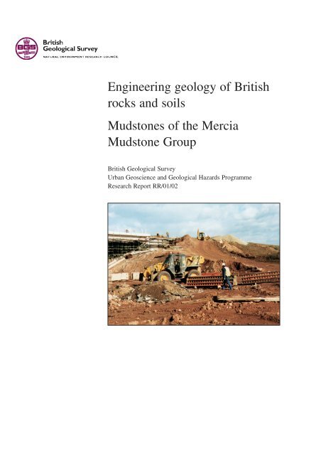
Cover illustration<br />
Earthwork operations in Mercia<br />
Mudstone for <strong>the</strong> Derby<br />
Sou<strong>the</strong>rn By-pass.<br />
Alan Forster, BGS © NERC<br />
The National Grid <strong>and</strong> o<strong>the</strong>r<br />
Ordnance Survey data are used<br />
with <strong>the</strong> permission <strong>of</strong> <strong>the</strong><br />
Controller <strong>of</strong> Her Majesty’s<br />
Stationery Office. Ordnance<br />
Survey licence number GD<br />
272191/2002.<br />
Bibliographical reference<br />
HOBBS, P R N AND 8 OTHERS.<br />
2002. <strong>Engineering</strong> <strong>geology</strong> <strong>of</strong><br />
<strong>British</strong> <strong>rocks</strong> <strong>and</strong> <strong>soils</strong> —<br />
<strong>Mudstones</strong> <strong>of</strong> <strong>the</strong> Mercia<br />
Mudstone Group. <strong>British</strong><br />
Geological Survey Research<br />
Report, RR/01/02. 106 pp.<br />
ISBN 085272 403 9<br />
© NERC 2002<br />
BRITISH GEOLOGICAL SURVEY<br />
Research Report RR/01/02<br />
<strong>Engineering</strong> <strong>geology</strong> <strong>of</strong> <strong>British</strong> <strong>rocks</strong><br />
<strong>and</strong> <strong>soils</strong><br />
<strong>Mudstones</strong> <strong>of</strong> <strong>the</strong> Mercia Mudstone<br />
Group<br />
Urban Geoscience <strong>and</strong> Geological Hazards Programme (UGGH)<br />
PRN Hobbs, J R Hallam, A Forster, D C Entwisle, L D Jones,<br />
A C Cripps, K J Northmore, S J Self <strong>and</strong> J L Meakin<br />
Keyworth, Nottingham <strong>British</strong> Geological Survey 2002
BRITISH GEOLOGICAL SURVEY<br />
The full range <strong>of</strong> survey publications is available from <strong>the</strong> BGS<br />
Sales Desk at Nottingham <strong>and</strong> Edinburgh; see contact details<br />
below or shop online at www.<strong>the</strong>bgs.co.uk The London<br />
Information Office maintains a reference collection <strong>of</strong> BGS publications<br />
including maps for consultation.<br />
The Survey publishes an annual catalogue <strong>of</strong> its maps <strong>and</strong> o<strong>the</strong>r<br />
publications; this catalogue is available from any <strong>of</strong> <strong>the</strong> BGS<br />
Sales Desks.<br />
The <strong>British</strong> Geological Survey carries out <strong>the</strong> geological survey<br />
<strong>of</strong> Great Britain <strong>and</strong> Nor<strong>the</strong>rn Irel<strong>and</strong> (<strong>the</strong> latter as an agency<br />
service for <strong>the</strong> government <strong>of</strong> Nor<strong>the</strong>rn Irel<strong>and</strong>), <strong>and</strong> <strong>of</strong> <strong>the</strong> surrounding<br />
continental shelf, as well as its basic research projects.<br />
It also undertakes programmes <strong>of</strong> <strong>British</strong> technical aid in <strong>geology</strong><br />
in developing countries as arranged by <strong>the</strong> Department for<br />
International Development <strong>and</strong> o<strong>the</strong>r agencies.<br />
The <strong>British</strong> Geological Survey is a component body <strong>of</strong> <strong>the</strong> Natural<br />
Environment Research Council.<br />
ii<br />
Keyworth, Nottingham NG12 5GG<br />
☎ 0115-936 3241 Fax: 0115-936 3488<br />
e-mail: sales@bgs.ac.uk<br />
www.bgs.ac.uk<br />
Shop online at: www.<strong>the</strong>bgs.co.uk<br />
Murchison House, West Mains Road, Edinburgh EH9 3LA<br />
☎ 0131-667 1000 Fax: 0131-668 2683<br />
e-mail: scotsales@bgs.ac.uk<br />
London Information Office at <strong>the</strong> Natural History Museum<br />
(Earth Galleries), Exhibition Road, South Kensington,<br />
London SW7 2DE<br />
☎ 020-7589 4090 Fax: 020-7584 8270<br />
☎ 020-7942 5344/45 e-mail:<br />
bgslondon@bgs.ac.uk<br />
Forde House, Park Five Business Centre, Harrier Way,<br />
Sowton, Exeter, Devon EX2 7HU<br />
☎ 01392-445271 Fax: 01392-445371<br />
Geological Survey <strong>of</strong> Nor<strong>the</strong>rn Irel<strong>and</strong>, 20 College Gardens,<br />
Belfast BT9 6BS<br />
☎ 028-9066 6595 Fax: 028-9066 2835<br />
Maclean Building, Crowmarsh Gifford, Wallingford,<br />
Oxfordshire OX10 8BB<br />
☎ 01491-838800 Fax: 01491-692345<br />
Parent Body<br />
Natural Environment Research Council Polaris House,<br />
North Star Avenue, Swindon, Wiltshire SN2 1EU<br />
☎ 01793-411500 Fax: 01793-411501<br />
www.nerc.ac.uk
‘As soon as we pass from steel <strong>and</strong> concrete to earth, <strong>the</strong><br />
omnipotence <strong>of</strong> <strong>the</strong>ory ceases to exist’<br />
Karl Terzaghi, 1936<br />
Proceedings <strong>of</strong> <strong>the</strong> first International Conference on Soil mechanics <strong>and</strong> Foundation<br />
<strong>Engineering</strong> — The relationship between soil mechanics <strong>and</strong> foundation engineering.<br />
‘In civil engineering projects <strong>the</strong> largest element <strong>of</strong> technical <strong>and</strong> financial<br />
risk usually lies in <strong>the</strong> ground’<br />
‘The ground is a vital element <strong>of</strong> all structures which rest on it or in it, <strong>and</strong> <strong>the</strong>re is no<br />
o<strong>the</strong>r element about which less is known’<br />
‘Insufficient attention is given to desk studies to provide valuable information at low cost’<br />
(from: Report <strong>of</strong> <strong>the</strong> Site Investigation Steering Group <strong>of</strong> <strong>the</strong> Institution <strong>of</strong> Civil Engineers on<br />
Site Investigation in Construction, Volume 1, Without Site Investigation Ground is a Hazard.<br />
Thomas Telford, London 1994.<br />
iii
Summary<br />
This report is <strong>the</strong> second <strong>of</strong> an on-going series that is<br />
examining <strong>the</strong> distribution, engineering properties <strong>and</strong><br />
regional variation <strong>of</strong> geological formations that are significant<br />
to civil engineering, construction <strong>and</strong> l<strong>and</strong>-use in<br />
Britain. In this volume <strong>the</strong> mudstone <strong>of</strong> <strong>the</strong> Mercia<br />
Mudstone Group is described in terms <strong>of</strong> its outcrop,<br />
mineral composition, geotechnical properties <strong>and</strong> engineering<br />
behaviour.<br />
Chapter 2 describes <strong>the</strong> global setting in which <strong>the</strong><br />
Triassic sediments were laid down <strong>and</strong> how <strong>the</strong> Mercia<br />
Mudstone Group, which comprises <strong>the</strong> major part <strong>of</strong> <strong>the</strong>se<br />
sediments in Britain, was formed under hot desert conditions<br />
in a series <strong>of</strong> interconnected, inl<strong>and</strong> basins with periodic<br />
connection to <strong>the</strong> sea. The variation in sedimentary environment<br />
gave rise to a range <strong>of</strong> different lithological associations<br />
that can be divided into five units that are traceable, in<br />
broad terms, across Britain. In some areas more detailed<br />
stratigraphic subdivisions have been identified.<br />
Chapter 3 examines <strong>the</strong> composition <strong>of</strong> <strong>the</strong> Mercia<br />
Mudstone Group in terms <strong>of</strong> its mineral components, how<br />
it varies as a consequence <strong>of</strong> <strong>the</strong> different sedimentary<br />
environments in which it was deposited <strong>and</strong> <strong>the</strong> physical<br />
<strong>and</strong> chemical changes after its deposition. It indicates how<br />
an underst<strong>and</strong>ing <strong>of</strong> <strong>the</strong> mineral composition <strong>of</strong> <strong>the</strong><br />
mudrock, especially <strong>of</strong> <strong>the</strong> clay fraction, can help to<br />
indicate its engineering behaviour particularly in terms <strong>of</strong><br />
plasticity <strong>and</strong> strength. The latter part <strong>of</strong> <strong>the</strong> chapter<br />
describes in detail <strong>the</strong> regional variation in lithology <strong>and</strong><br />
mineral composition <strong>of</strong> <strong>the</strong> mudstone <strong>of</strong> <strong>the</strong> Mercia<br />
Mudstone Group.<br />
The published literature <strong>of</strong> <strong>the</strong> past 30 years concerning<br />
<strong>the</strong> engineering behaviour <strong>of</strong> <strong>the</strong> Mercia Mudstone is<br />
reviewed in Chapter 4, with regard to mineralogy, index<br />
properties, consolidation, strength, deformability, swelling,<br />
compaction, permeability, rock mass properties <strong>and</strong> geophysical<br />
properties. Particular attention is paid to <strong>the</strong> development<br />
<strong>of</strong> schemes for describing wea<strong>the</strong>red material.<br />
iv<br />
Chapter 5 looks briefly at <strong>the</strong> problems encountered in<br />
coring <strong>and</strong> sampling Mercia Mudstone due to its mechanical<br />
nature, which has characteristics common to both soil<br />
<strong>and</strong> rock, resulting in behaviour which is predominately<br />
influenced by wea<strong>the</strong>ring <strong>and</strong> jointing ra<strong>the</strong>r than by sedimentary<br />
discontinuities. Some recommendations are made<br />
as to <strong>the</strong> minimum procedures necessary to ensure<br />
adequate recovery <strong>of</strong> <strong>the</strong> material for engineering purposes.<br />
The structure, compilation <strong>and</strong> method <strong>of</strong> statistical<br />
analysis <strong>of</strong> <strong>the</strong> project's geotechnical database are<br />
described in Chapter 6. Emphasis was placed on <strong>the</strong> collection<br />
<strong>of</strong> only good quality, reliable data with a good geographical<br />
spread ra<strong>the</strong>r than including poor quality data<br />
that would add little useful information <strong>and</strong> might obscure<br />
<strong>the</strong> interpretation. The analysis <strong>of</strong> <strong>the</strong> database forms <strong>the</strong><br />
basis for Chapter 7 which describes <strong>the</strong> geotechnical properties<br />
<strong>of</strong> <strong>the</strong> Mercia Mudstone, how <strong>the</strong>y vary stratigraphically,<br />
regionally <strong>and</strong> with wea<strong>the</strong>ring grade. Extended box,<br />
scatter line <strong>and</strong> bubble plots are used to illustrate <strong>the</strong><br />
variation <strong>of</strong> index test results including particle size,<br />
chemistry, consolidation, compaction, swell/shrink <strong>and</strong><br />
strength. Statistical summaries <strong>of</strong> <strong>the</strong> geotechnical data are<br />
presented as tables <strong>and</strong> extended box plots in <strong>the</strong><br />
Appendix. The determination <strong>of</strong> particle size, its relation to<br />
clay mineral content <strong>and</strong> <strong>the</strong> problems encountered caused<br />
by <strong>the</strong> incomplete disaggregation <strong>of</strong> clay particles are<br />
discussed in detail.<br />
The use <strong>of</strong> in situ testing <strong>of</strong> Mercia Mudstone is<br />
described in Chapter 8. These tests have been developed in<br />
response to <strong>the</strong> considerable difficulties that are experienced<br />
in <strong>the</strong> determination <strong>of</strong> <strong>the</strong> mass strength <strong>and</strong> mass<br />
stiffness <strong>of</strong> weak <strong>rocks</strong> such as <strong>the</strong> Mercia Mudstone due to<br />
<strong>the</strong> fissured nature <strong>of</strong> <strong>the</strong> unwea<strong>the</strong>red rock. Pressure meter<br />
tests, plate bearing tests <strong>and</strong> penetration tests (static,<br />
dynamic <strong>and</strong> st<strong>and</strong>ard) are described.<br />
Chapter 9 summarises <strong>the</strong> main conclusions <strong>and</strong> is<br />
followed by a list <strong>of</strong> references.
Preface<br />
The <strong>British</strong> Geological Survey (BGS) has a responsibility<br />
for providing information on <strong>the</strong> physical properties <strong>of</strong><br />
<strong>rocks</strong> <strong>and</strong> sediments to enhance a wide range <strong>of</strong> activities<br />
both on l<strong>and</strong> <strong>and</strong> <strong>of</strong>fshore. The BGS maintains laboratory<br />
facilities <strong>and</strong> undertakes a wide range <strong>of</strong> geotechnical <strong>and</strong><br />
geophysical tests on core samples from boreholes, block<br />
samples from trenches, <strong>and</strong> samples from rock exposures<br />
in survey areas. As <strong>the</strong> national repository for geoscience<br />
data in <strong>the</strong> UK, <strong>the</strong> Survey also holds an extensive archive<br />
<strong>of</strong> geotechnical data in <strong>the</strong> form <strong>of</strong> site investigation<br />
reports acquired from <strong>the</strong> public domain. The geotechnical<br />
data acquired from <strong>the</strong>se surveys are currently being<br />
brought toge<strong>the</strong>r in one common database format, via<br />
specific studies related to various geological map sheets or<br />
general studies such as <strong>the</strong> <strong>Engineering</strong> <strong>geology</strong> <strong>of</strong> <strong>British</strong><br />
<strong>rocks</strong> <strong>and</strong> <strong>soils</strong> project, <strong>the</strong> latest report <strong>of</strong> which is<br />
described below.<br />
Early work concentrated on <strong>the</strong> production <strong>of</strong> engineering<br />
geological maps <strong>and</strong> over <strong>the</strong> years a wide range <strong>of</strong> different<br />
types <strong>of</strong> maps have been produced both for BGS projects<br />
<strong>and</strong> specialised commissioned studies for <strong>the</strong> Department <strong>of</strong><br />
Environment, Transport <strong>and</strong> <strong>the</strong> Regions (DETR). These<br />
maps were developed with an associated database <strong>and</strong> <strong>of</strong>ten<br />
a table, in which <strong>the</strong> engineering properties <strong>of</strong> all <strong>the</strong> formations<br />
on <strong>the</strong> map were assessed from <strong>the</strong> point <strong>of</strong> view <strong>of</strong><br />
civil engineering construction. This approach produced a<br />
generalised geotechnical <strong>and</strong> geophysical appraisal <strong>of</strong> <strong>the</strong><br />
geological formations encountered on <strong>the</strong> maps, but did not<br />
examine <strong>the</strong> variability <strong>of</strong> <strong>the</strong>se properties for specific formations<br />
outside <strong>the</strong> area <strong>of</strong> interest. Hence, <strong>the</strong> present<br />
approach <strong>of</strong> studying a single formation in more detail over<br />
its total extent both vertically <strong>and</strong> laterally was instigated.<br />
The Mercia Mudstone study described below is <strong>the</strong> second<br />
in this series <strong>of</strong> geotechnical studies.<br />
<strong>Engineering</strong> Geology <strong>of</strong> <strong>British</strong> Rocks <strong>and</strong> Soils<br />
Previous project reports:<br />
Gault Clay. 1994. <strong>British</strong> Geological Survey Technical Report WN/94/31<br />
Future project reports for studies currently underway:<br />
Lambeth Group (draft report in preparation)<br />
Lias<br />
Brickearth<br />
v<br />
Although it is not <strong>the</strong> intention to look at every geological<br />
formation in <strong>the</strong> UK, <strong>the</strong> overall project is intended to study<br />
those formations which present serious engineering problems<br />
or upon which significant areas <strong>of</strong> <strong>the</strong> built environment are<br />
founded. It is anticipated that <strong>the</strong> project will take a number<br />
<strong>of</strong> years to characterise <strong>the</strong> necessary formations.<br />
The study <strong>of</strong> <strong>the</strong> second formation has also refined <strong>the</strong><br />
methodology established by <strong>the</strong> first study, <strong>of</strong> <strong>the</strong> Gault<br />
Clay, mainly with regard to improving <strong>the</strong> selection <strong>and</strong><br />
databasing <strong>of</strong> geotechnical data from site investigation<br />
reports.<br />
The <strong>Engineering</strong> <strong>geology</strong> <strong>of</strong> <strong>British</strong> <strong>rocks</strong> <strong>and</strong> <strong>soils</strong><br />
project thanks <strong>the</strong> many people who have helped in <strong>the</strong><br />
course <strong>of</strong> this study. Special thanks are due to <strong>the</strong> project's<br />
advisory panel <strong>of</strong> Mr David Patterson (Highways Agency),<br />
Dr John Perry (Mott MacDonald) <strong>and</strong> Pr<strong>of</strong> Mike<br />
Rosenbaum (Nottingham Trent University) whose constructive<br />
criticism <strong>and</strong> advice are invaluable in ensuring <strong>the</strong><br />
project aims <strong>and</strong> outputs remain focussed on <strong>the</strong> needs <strong>of</strong><br />
<strong>the</strong> user community, <strong>and</strong> in guiding future progress.<br />
Thanks are also due to <strong>the</strong> many staff <strong>of</strong> <strong>the</strong> <strong>British</strong><br />
Geological Survey, not named in <strong>the</strong> report as co-authors,<br />
who have contributed to <strong>the</strong> success <strong>of</strong> <strong>the</strong> project.<br />
David C Holmes<br />
Programme Director<br />
(Environment & Hazards)<br />
<strong>British</strong> Geological Survey Keyworth<br />
Nottingham<br />
March 2002
Contents<br />
Summary iv<br />
Preface v<br />
1 Introduction 1<br />
1.1 Background to report 1<br />
1.2 Methodology 1<br />
2 Geological background 2<br />
2.1 Global setting 2<br />
2.2 Mercia Mudstone deposition in Britain 3<br />
2.3 Lithostratigraphical classification 4<br />
2.4 Lithological characteristics 4<br />
2.5 Marginal conglomerates 6<br />
2.6 Folding <strong>and</strong> faulting 7<br />
3 Mineralogical considerations 8<br />
3.1 Introduction 8<br />
3.2 Diagenesis 8<br />
3.3 Mineral composition 9<br />
3.4 Regional mineralogical variation 12<br />
4 Geotechnical literature review 19<br />
4.1 Introduction 19<br />
4.2 Wea<strong>the</strong>ring <strong>and</strong> classification 19<br />
4.3 Lithological considerations 21<br />
4.4 Index properties 23<br />
4.5 Consolidation 24<br />
4.6 Strength <strong>and</strong> deformability 24<br />
4.7 Swelling, shrinkage <strong>and</strong> durability 25<br />
4.8 Compaction 25<br />
4.9 Permeability 26<br />
4.10 Geophysical properties 26<br />
4.11 Rock mass indices 26<br />
5 Drilling <strong>and</strong> sampling 27<br />
5.1 Introduction 27<br />
5.2 Drilling 27<br />
5.3 Sampling 28<br />
6 Database design <strong>and</strong> method <strong>of</strong> analysis 29<br />
6.1 Data sources <strong>and</strong> coverage 29<br />
6.2 Database structure 29<br />
6.3 Data entry 29<br />
6.4 Data quality 30<br />
6.5 Data analysis 31<br />
6.6 Data subdivision <strong>and</strong> presentation 31<br />
6.7 Box plots 32<br />
6.8 Extended box plots 32<br />
7 Geotechnical database — results <strong>of</strong> analysis 34<br />
7.1 General 34<br />
7.2 Density <strong>and</strong> moisture content 34<br />
7.3 Particle size 34<br />
7.4 Plasticity 37<br />
7.5 Sulphate, pH, <strong>and</strong> o<strong>the</strong>r chemical tests 44<br />
7.6 Strength 45<br />
7.7 Consolidation 51<br />
7.8 Deformability 52<br />
7.9 Permeability 53<br />
7.10 Compaction 54<br />
7.11 Swelling <strong>and</strong> shrinkage 54<br />
vii<br />
8 In situ testing 57<br />
8.1 Introduction 57<br />
8.2 Static <strong>and</strong> dynamic penetration tests 57<br />
8.3 Pressure meter tests 57<br />
8.4 Plate-bearing tests 58<br />
8.5 St<strong>and</strong>ard penetration tests 59<br />
8.6 Permeability tests 60<br />
9 Conclusions 61<br />
9.1 Geology 61<br />
9.2 Mineralogy 61<br />
9.3 Sampling <strong>and</strong> testing 61<br />
9.4 Geotechnical database 62<br />
9.5 <strong>Engineering</strong> behaviour 62<br />
References<br />
Appendix<br />
65<br />
Statistical summary <strong>of</strong> geotechnical data 70<br />
Figures<br />
2.1 Supercontinent <strong>of</strong> Pangea in <strong>the</strong> late Carboniferous<br />
Period 325 million years ago formed by <strong>the</strong> collision<br />
<strong>of</strong> <strong>the</strong> continental masses <strong>of</strong> Laurasia <strong>and</strong> Gondwana<br />
(after Keary <strong>and</strong> Vine, 1990) 2<br />
2.2 Permo-Triassic regional tectonic framework <strong>of</strong> <strong>the</strong><br />
North Atlantic region (after Chadwick <strong>and</strong> Evans,<br />
1995) 2<br />
2.3 Triassic lith<strong>of</strong>acies in Engl<strong>and</strong> <strong>and</strong> <strong>the</strong> Sou<strong>the</strong>rn<br />
North Sea (after Warrington <strong>and</strong> Ivimey-Cook,<br />
1992) 3<br />
2.4 Outcrop <strong>of</strong> <strong>the</strong> Mercia Mudstone Group in Britain 3<br />
2.5 Gentle folding <strong>and</strong> minor faulting in Mercia<br />
Mudstone at Haven Cliff, east <strong>of</strong> Seaton, Devon 7<br />
2.6 Minor fault in <strong>the</strong> Cropwell Bishop <strong>and</strong> Blue Anchor<br />
formations <strong>of</strong> <strong>the</strong> Mercia Mudstone with Westbury<br />
Formation exposed at <strong>the</strong> top right <strong>of</strong> <strong>the</strong> section at<br />
Cropwell Bishop, Nottinghamshire 7<br />
3.1 Gypsum working in <strong>the</strong> Cropwell Bishop Formation<br />
<strong>of</strong> <strong>the</strong> Mercia Mudstone Group in <strong>the</strong> quarry at<br />
Cropwell Bishop 8<br />
3.2 The distribution <strong>of</strong> carbonate <strong>and</strong> evaporite minerals<br />
in <strong>the</strong> Mercia Mudstone Group 11<br />
3.3 The distribution <strong>of</strong> clay minerals in <strong>the</strong> Mercia<br />
Mudstone Group 13<br />
4.1 Unwea<strong>the</strong>red (Zone 1) jointed Mercia Mudstone<br />
(Cropwell Bishop Formation) classifiable as a ‘weak<br />
rock’ 19<br />
4.2 Fully wea<strong>the</strong>red Mercia Mudstone (Zone 4b) reddish<br />
brown <strong>and</strong> greenish/grey silty clay 19<br />
4.3 Wea<strong>the</strong>red Mercia Mudstone near Honiton, Devon.<br />
‘Moderately wea<strong>the</strong>red’ material (Zone 3a) near surface<br />
becomes ‘slightly wea<strong>the</strong>red’ (Zone 2) with depth but is<br />
‘highly to fully wea<strong>the</strong>red’ (Zone 4a/4b) at <strong>the</strong> bottom<br />
<strong>of</strong> <strong>the</strong> section as shown by <strong>the</strong> smearing <strong>of</strong> material to<br />
left <strong>of</strong> <strong>the</strong> spade 20
4.4 Stress vs strain graph for Mercia Mudstone<br />
Wea<strong>the</strong>ring Zones 1, 3 <strong>and</strong> 4 (drained cell pressure<br />
68.95 KN/m 2 ) showing change from brittle to plastic<br />
behaviour as wea<strong>the</strong>ring progresses (after Ch<strong>and</strong>ler,<br />
1969) 21<br />
4.5 Classification <strong>of</strong> mud<strong>rocks</strong> suggested by Grainger,<br />
1985 22<br />
6.1 Outcrop <strong>of</strong> <strong>the</strong> Mercia Mudstone Group showing<br />
areas used for <strong>the</strong> statistical analysis <strong>of</strong> <strong>the</strong> geotechnical<br />
database 29<br />
6.2 Table structure for <strong>the</strong> geotechnical database 30<br />
6.3 St<strong>and</strong>ard box <strong>and</strong> whisker plot 32<br />
6.4 Structure <strong>of</strong> extended box plots for ‘normal’ distribution<br />
<strong>of</strong> data values 33<br />
7.1 Particle size grading envelopes (all data) 35<br />
7.2 Particle size grading curves (Area 1, subdivided by<br />
formation) 36<br />
7.3 Particle size grading curves (Area 2, subdivided by<br />
wea<strong>the</strong>ring zone, WG) 36<br />
7.4 Activity plot, %
1 Introduction<br />
1.1 BACKGROUND TO THE REPORT<br />
The Mercia Mudstone Group is a sequence <strong>of</strong> predominantly<br />
mudrock strata which underlies much <strong>of</strong> central <strong>and</strong><br />
sou<strong>the</strong>rn Engl<strong>and</strong> <strong>and</strong> on which many urban areas <strong>and</strong> <strong>the</strong>ir<br />
attendant infrastructure are built. It is <strong>the</strong> mudstone that is<br />
most commonly encountered in construction <strong>and</strong> it is <strong>the</strong><br />
mudstone with which this report is primarily concerned. In<br />
order to assist readability this report uses <strong>the</strong> widely used,<br />
though stratigraphically inaccurate, term ‘Mercia<br />
Mudstone’ ra<strong>the</strong>r than <strong>the</strong> strictly correct but repetitious<br />
term ‘mudstone <strong>of</strong> <strong>the</strong> Mercia Mudstone Group’ or ‘Mercia<br />
Mudstone Group mudstone’.<br />
Although <strong>the</strong> Mercia Mudstone appears to cause few<br />
serious geotechnical problems compared with o<strong>the</strong>r, higher<br />
plasticity, clays (Jones, 2000) it is significant to <strong>the</strong> construction<br />
industry because it is frequently encountered in<br />
civil engineering activities involving foundations, excavations<br />
<strong>and</strong> earthworks. Its nature is such that its properties<br />
may vary between a soil <strong>and</strong> a rock depending on its<br />
detailed lithology <strong>and</strong> its state <strong>of</strong> wea<strong>the</strong>ring. As a result <strong>of</strong><br />
this, in some cases, weaker material may be found below<br />
stronger ra<strong>the</strong>r than <strong>the</strong> more normal wea<strong>the</strong>ring progression<br />
where <strong>the</strong> weakest material occurs at <strong>the</strong> surface <strong>and</strong><br />
becomes fresher <strong>and</strong> stronger with depth. Consequently<br />
sampling <strong>and</strong> testing is difficult because <strong>the</strong> material may<br />
not be suited to ei<strong>the</strong>r soil or rock techniques. There is a<br />
significant problem with regard to measuring particle size<br />
grading <strong>and</strong> plasticity due to <strong>the</strong> difficulties with disaggregating<br />
<strong>the</strong> component particles. Some parts <strong>of</strong> <strong>the</strong> Mercia<br />
Mudstone sequence may be subject to shrinking <strong>and</strong><br />
swelling with changes in moisture content to a sufficient<br />
degree that structural damage to buildings or disruption in<br />
some types <strong>of</strong> construction work is caused.<br />
The Mercia Mudstone Group contains s<strong>and</strong>stone beds<br />
<strong>and</strong> evaporite minerals, mainly halite (sodium chloride)<br />
<strong>and</strong> gypsum (calcium sulphate, 2H 2O). These lithologies<br />
can cause significant problems to construction but <strong>the</strong>y<br />
have not been addressed by this study on <strong>the</strong> basis that it is<br />
<strong>the</strong> mudstones that represent by far <strong>the</strong> greater part <strong>of</strong> <strong>the</strong><br />
1<br />
sequence. O<strong>the</strong>r reports may address <strong>the</strong>se materials in <strong>the</strong><br />
future. Halite is very soluble in water <strong>and</strong> is never encountered<br />
at <strong>the</strong> natural ground surface in this country having<br />
been removed by groundwater at some depth. Similarly<br />
gypsum, though less soluble, is frequently absent in <strong>the</strong><br />
near surface zone. S<strong>and</strong>stone represents a small proportion<br />
<strong>of</strong> <strong>the</strong> sequence in most areas <strong>and</strong> is rarely a problem to<br />
construction.<br />
This report on <strong>the</strong> mudstone <strong>of</strong> <strong>the</strong> Mercia Mudstone<br />
Group is <strong>the</strong> second <strong>of</strong> a series on <strong>the</strong> <strong>rocks</strong> <strong>and</strong> <strong>soils</strong> <strong>of</strong><br />
Britain which aims to satisfy a need <strong>of</strong> geologists <strong>and</strong><br />
engineers for reference works describing <strong>the</strong> engineering<br />
behaviour <strong>of</strong> important geological formations.<br />
1.2 METHODOLOGY<br />
The properties <strong>and</strong> behaviour <strong>of</strong> geological materials are<br />
controlled by <strong>the</strong>ir texture, structure <strong>and</strong> mineral composition.<br />
These factors are a reflection <strong>of</strong> <strong>the</strong>ir depositional<br />
environment, diagenesis <strong>and</strong> subsequent tectonic history<br />
that also have a major influence on <strong>the</strong> current engineering<br />
behaviour <strong>of</strong> <strong>the</strong> strata as a whole. Also, <strong>the</strong> near-surface<br />
zone has been influenced by Earth surface processes acting<br />
in <strong>the</strong> more recent past. In many instances <strong>the</strong> behaviour <strong>of</strong><br />
<strong>the</strong> material cannot be predicted unless <strong>the</strong> recent geological<br />
history <strong>of</strong> <strong>the</strong> site is understood.<br />
The Mercia Mudstone study comprised several interdependent<br />
parts. An extensive literature search was carried<br />
out at <strong>the</strong> start <strong>of</strong> <strong>the</strong> study to collect <strong>and</strong> review previous<br />
work thus guiding <strong>the</strong> activities <strong>of</strong> <strong>the</strong> study. At <strong>the</strong> same<br />
time an extensive geotechnical database was assembled<br />
from high quality site investigation reports which was <strong>the</strong>n<br />
analysed to establish <strong>the</strong> typical range <strong>and</strong> values <strong>of</strong> <strong>the</strong><br />
most commonly determined geotechnical parameters <strong>and</strong> to<br />
look for regional variation in geotechnical properties.<br />
When <strong>the</strong> scope <strong>of</strong> <strong>the</strong> database was clear, a sampling <strong>and</strong><br />
testing programme was carried out to investigate in more<br />
detail some <strong>of</strong> <strong>the</strong> geotechnical properties <strong>and</strong> behaviour<br />
not satisfactorily covered in <strong>the</strong> database.
2 Geological background<br />
2.1 GLOBAL SETTING<br />
The crustal plates <strong>of</strong> <strong>the</strong> Earth's surface moved toge<strong>the</strong>r<br />
during <strong>the</strong> late Carboniferous Period resulting in <strong>the</strong> fusion <strong>of</strong><br />
all <strong>the</strong> continental masses to form <strong>the</strong> single, super continent<br />
<strong>of</strong> Pangea (Figure 2.1). However, at <strong>the</strong> start <strong>of</strong> <strong>the</strong> Permian<br />
tensional stresses within <strong>the</strong> super continent resulted in <strong>the</strong><br />
formation <strong>of</strong> a large infra-continental basin at a latitude <strong>of</strong> 15<br />
to 20 north <strong>of</strong> <strong>the</strong> equator. This is a similar geographical<br />
location on <strong>the</strong> Earth’s surface to that <strong>of</strong> <strong>the</strong> current position<br />
<strong>of</strong> <strong>the</strong> Sahara Desert in nor<strong>the</strong>rn Africa. This rifting was to<br />
lead ultimately to <strong>the</strong> opening <strong>of</strong> <strong>the</strong> Atlantic Ocean far<strong>the</strong>r to<br />
<strong>the</strong> west. To <strong>the</strong> south, <strong>the</strong> Variscan mountain range <strong>of</strong> <strong>the</strong><br />
Hercynian fold belt separated <strong>the</strong> developing basin from <strong>the</strong><br />
Tethys Ocean <strong>and</strong> <strong>the</strong> continental mass that was to become<br />
Africa. To <strong>the</strong> north lay <strong>the</strong> l<strong>and</strong>mass created when Laurentia<br />
had fused with Greenl<strong>and</strong> <strong>and</strong> Fenno-Sc<strong>and</strong>ia to form<br />
Laurasia (Figure 2.2).<br />
The climate <strong>of</strong> <strong>the</strong> basin was interpreted by Warrington<br />
<strong>and</strong> Ivimey-Cook (1992) as being <strong>of</strong> a monsoonal nature with<br />
prevailing winds from <strong>the</strong> north-east or east. When <strong>the</strong> wind<br />
met <strong>the</strong> Variscan mountains it resulted in high rainfall events<br />
which led to periodic floods draining northward into <strong>the</strong><br />
basin. The deposits <strong>of</strong> <strong>the</strong> Triassic Period in what is now<br />
called nor<strong>the</strong>rn Europe were laid down within this<br />
framework. The Triassic Period extended from about 250 Ma<br />
to 205 Ma before <strong>the</strong> present time (Forster <strong>and</strong> Warrington,<br />
1985) <strong>and</strong> derives its name 'Triassic' from <strong>the</strong> threefold<br />
lithostratigraphic division, recognised in Germany, <strong>of</strong><br />
Bunts<strong>and</strong>stein (s<strong>and</strong>stone), Muschelkalk (carbonate) <strong>and</strong><br />
Keuper (mudstone). However, in Britain, which is on <strong>the</strong><br />
Figure 2.1 Supercontinent <strong>of</strong> Pangea in <strong>the</strong> late<br />
Carboniferous Period 325 million years ago formed by <strong>the</strong><br />
collision <strong>of</strong> <strong>the</strong> continental masses <strong>of</strong> Laurasia <strong>and</strong><br />
Gondwana (after Keary <strong>and</strong> Vine, 1990).<br />
2<br />
0 1000 km<br />
LAURENTIAN–GREENLAND SHIELD<br />
RH<br />
CSB<br />
RT<br />
WA<br />
FR<br />
M<br />
MNS<br />
NO RTH<br />
NPB<br />
CHESHIRE BASIN<br />
EIS SPB<br />
WB<br />
WC<br />
ATLANTIC – ARCTIC RIFT<br />
FENNO–SCANDIAN SHIELD<br />
VARISCAN FRONT<br />
western margin <strong>of</strong> <strong>the</strong> basin, this three-fold division does not<br />
represent <strong>the</strong> local sequence. The Muschelkalk facies is<br />
missing <strong>and</strong> Triassic <strong>rocks</strong> are represented by <strong>the</strong> Sherwood<br />
S<strong>and</strong>stone Group (formerly Bunter S<strong>and</strong>stone), Mercia<br />
Mudstone Group (formerly Keuper Marl) <strong>and</strong> <strong>the</strong> Penarth<br />
Group (formerly <strong>the</strong> Rhaetic). These have been described by<br />
Warrington <strong>and</strong> Ivimey-Cook (1992) who identified five<br />
lithological associations within <strong>the</strong> Triassic (Figure 2.3).<br />
The lowest division, below <strong>the</strong> Hardegsen<br />
Disconformity, comprises an unfossiliferous sequence <strong>of</strong><br />
s<strong>and</strong>stone, pebbly s<strong>and</strong>stone <strong>and</strong> conglomeratic s<strong>and</strong>stone<br />
laid down as channel deposits in a braided stream fluvial<br />
environment <strong>of</strong> a major, northward-flowing river system.<br />
This environment lasted for approximately seven million<br />
years at <strong>the</strong> start <strong>of</strong> <strong>the</strong> Triassic Period (Scythian) <strong>and</strong> <strong>the</strong><br />
deposits are now preserved as <strong>the</strong> lower part <strong>of</strong> <strong>the</strong><br />
Sherwood S<strong>and</strong>stone Group. Above this is a complex<br />
basinal sequence, between <strong>the</strong> Hardegsen unconformity<br />
<strong>and</strong> <strong>the</strong> Arden S<strong>and</strong>stone <strong>and</strong> its equivalents, which spans<br />
about 20 million years from Scythian to Carnian times.<br />
During <strong>the</strong> early part <strong>of</strong> this period <strong>the</strong> regional climate<br />
became progressively more arid <strong>and</strong> inl<strong>and</strong> sabkhas, saline<br />
mudflats <strong>and</strong> temporary lakes slowly advanced southwards<br />
VG<br />
LBM<br />
PB<br />
R F<br />
OG<br />
VARISCAN MOUNTAINS<br />
Figure 2.2 Permo-Triassic regional tectonic framework <strong>of</strong><br />
<strong>the</strong> North Atlantic region. CB = Cheshire Basin, WB =<br />
Worcester Basin, WC = Wessex Basin, NPB = North<br />
Permian Basin, SPB = South Permian Basin, LBM =<br />
London Brabant Massif (after Chadwick <strong>and</strong> Evans, 1995).
JURASSIC<br />
205<br />
5Ma<br />
Rhaetian<br />
TRIASSIC<br />
LATE<br />
MIDDLE<br />
EARLY<br />
PERMIAN<br />
Norian<br />
Carnian<br />
Ladinian<br />
Anisian<br />
(Scythian)<br />
250<br />
5Ma<br />
SHERWOOD<br />
LIAS GROUP<br />
PENARTH GROUP<br />
MERCIA<br />
ARDEN SANDSTONE MEMBER<br />
MUDSTONE<br />
GROUP<br />
SANDSTONE Hardegsen Disconformity<br />
GROUP<br />
ESKDALE GROUP<br />
Figure 2.3 Triassic lith<strong>of</strong>acies in Engl<strong>and</strong> <strong>and</strong> <strong>the</strong> Sou<strong>the</strong>rn<br />
North Sea (after Warrington <strong>and</strong> Ivimey-Cook, 1992).<br />
to replace <strong>the</strong> fluvial environments <strong>of</strong> <strong>the</strong> Sherwood<br />
S<strong>and</strong>stone Group. In <strong>the</strong> south <strong>and</strong> west <strong>of</strong> Britain, fluvial<br />
s<strong>and</strong>stones (Sherwood S<strong>and</strong>stone) pass laterally into<br />
interbedded s<strong>and</strong>stones, siltstones <strong>and</strong> mudstones, which<br />
were deposited in a fresh to brackish water estuarine or<br />
intertidal environment <strong>and</strong> <strong>the</strong>mselves pass into evaporite<br />
(including halite) bearing mudstone (Mercia Mudstone <strong>and</strong><br />
Haisborough Groups) which are found to <strong>the</strong> north-west.<br />
The base <strong>of</strong> <strong>the</strong> Mercia Mudstone Group is thus<br />
diachronous with <strong>the</strong> lowest beds <strong>of</strong> <strong>the</strong> group becoming<br />
progressively younger southwards. Thick Mercia Mudstone<br />
sequences continued to accumulate within fault-bounded<br />
basins, but deposition gradually transgressed onto adjacent<br />
basin margins, so that <strong>the</strong> group generally overlies <strong>and</strong><br />
confines <strong>the</strong> major, early Triassic Sherwood S<strong>and</strong>stone<br />
Group, but locally overlaps <strong>the</strong> group to overlie <strong>rocks</strong> <strong>of</strong><br />
Carboniferous or older age <strong>of</strong> adjacent high ground.<br />
The Arden S<strong>and</strong>stone, <strong>and</strong> equivalent s<strong>and</strong>stone bodies in<br />
o<strong>the</strong>r areas, indicates a brief episode <strong>of</strong> deltaic or estuarine<br />
deposition in which grey-green siltstone, mudstone <strong>and</strong> thick<br />
s<strong>and</strong>stone beds were deposited over a period <strong>of</strong> a few million<br />
years. Following <strong>the</strong> Arden S<strong>and</strong>stone, during a period <strong>of</strong> 12<br />
million years from <strong>the</strong> end <strong>of</strong> <strong>the</strong> Carnian into Rhaetian<br />
times, typical Mercia Mudstone Group deposits were laid<br />
down, similar to <strong>the</strong> basinal argillaceous evaporite bearing<br />
deposits below <strong>the</strong> Arden S<strong>and</strong>stone. They included both<br />
subaqueous <strong>and</strong> subaerial deposits but only sulphates are<br />
present in <strong>the</strong> evaporite sequences because <strong>the</strong>y are <strong>the</strong> result<br />
<strong>of</strong> deposition from interstitial brines or shallow water, hypersaline<br />
sabkha environments. The sequence ends in late<br />
Triassic (Rhaetian) times with an unconformity that marks<br />
<strong>the</strong> start <strong>of</strong> a widespread marine transgression. Rising sea<br />
level flooded <strong>the</strong> mudflats <strong>and</strong>, initially, laid down <strong>the</strong><br />
widespread, dark grey to black marine mudstone <strong>of</strong> <strong>the</strong><br />
Westbury Formation <strong>of</strong> <strong>the</strong> Lower Penarth Group that was<br />
followed by <strong>the</strong> mudstone <strong>and</strong> thin limestone beds <strong>of</strong> <strong>the</strong><br />
Upper Penarth <strong>and</strong> Lias Groups. The Mercia Mudstone<br />
Group that comprises <strong>the</strong> deposits between <strong>the</strong> Sherwood<br />
S<strong>and</strong>stone <strong>and</strong> <strong>the</strong> Penarth Group is described in more detail<br />
regarding lithological variations across its outcrop in <strong>the</strong> UK<br />
in <strong>the</strong> following section.<br />
3<br />
2.2 MERCIA MUDSTONE DEPOSITION IN<br />
BRITAIN<br />
The stresses that formed <strong>the</strong> main basin to <strong>the</strong> east <strong>of</strong> Britain<br />
also led to <strong>the</strong> formation <strong>of</strong> a series <strong>of</strong> small, fault-bounded,<br />
subsiding basins in sou<strong>the</strong>rn, central <strong>and</strong> north-west Engl<strong>and</strong><br />
that were controlled by <strong>the</strong> reactivation <strong>of</strong> fractures in <strong>the</strong><br />
basement. Thus, in <strong>the</strong> south-west <strong>the</strong> controlling faults have<br />
an east–west (Variscoid) trend, in <strong>the</strong> Midl<strong>and</strong>s a north–south<br />
(Malvernoid) trend <strong>and</strong> in <strong>the</strong> north a north-east–south-west<br />
(Caledonoid) trend (Chadwick <strong>and</strong> Evans, 1995).<br />
The Mercia Mudstone Group was deposited in a mudflat<br />
environment in three main ways: settling-out <strong>of</strong> mud <strong>and</strong><br />
silt in temporary lakes; rapid deposition <strong>of</strong> sheets <strong>of</strong> silt<br />
<strong>and</strong> fine s<strong>and</strong> by flash floods; <strong>and</strong> <strong>the</strong> accumulation <strong>of</strong><br />
wind-blown dust on <strong>the</strong> wet mudflat surface. It is<br />
composed mainly <strong>of</strong> red <strong>and</strong>, less commonly, green <strong>and</strong><br />
grey mudstones <strong>and</strong> siltstones. Substantial deposits <strong>of</strong><br />
halite occur in <strong>the</strong> thicker, basinal successions <strong>of</strong> Somerset,<br />
Worcestershire, Staffordshire <strong>and</strong> Cheshire. Sulphate<br />
deposits (gypsum <strong>and</strong> anhydrite) <strong>and</strong> s<strong>and</strong>stone beds are<br />
common at some stratigraphical levels <strong>and</strong> are minor constituents<br />
throughout <strong>the</strong> remainder <strong>of</strong> <strong>the</strong> group. The<br />
outcrop <strong>of</strong> <strong>the</strong> Mercia Mudstone Group extends northwards<br />
from Lyme Bay, through Somerset <strong>and</strong> on to both sides <strong>of</strong><br />
<strong>the</strong> Severn Estuary (Figure 2.4). It continues northwards<br />
through Hereford <strong>and</strong> Worcester before broadening out to<br />
underlie much <strong>of</strong> <strong>the</strong> central Midl<strong>and</strong>s. The outcrop bifur-<br />
Figure 2.4 Outcrop <strong>of</strong> <strong>the</strong> Mercia Mudstone Group in<br />
Britain. The numbered regions correspond to those shown in<br />
Table 2.1, as follows: 1. Wessex Basin; 2. Somerset/Avon/ South<br />
Wales; 3. Worcester/Knowle Basins; 4. Stafford/Needwood Basins;<br />
5. Cheshire Basin; 6. West Lancashire; 7. Carlisle Basin;<br />
8. East Midl<strong>and</strong>s/NE Engl<strong>and</strong>.
cates around <strong>the</strong> Pennine Anticline, with <strong>the</strong> eastern limb<br />
running through Nottinghamshire into <strong>the</strong> Vale <strong>of</strong> York,<br />
before eventually reaching <strong>the</strong> North Sea coast at Teesside.<br />
The western limb underlies nor<strong>the</strong>rn Shropshire, Cheshire<br />
<strong>and</strong> Merseyside <strong>and</strong> much <strong>of</strong> <strong>the</strong> Formby <strong>and</strong> Fylde peninsulas,<br />
passing <strong>of</strong>fshore below <strong>the</strong> Irish Sea before<br />
extending onshore again on <strong>the</strong> nor<strong>the</strong>rn side <strong>of</strong> <strong>the</strong> Lake<br />
District near Carlisle. In Cheshire, Warwickshire, <strong>the</strong> Vale<br />
<strong>of</strong> York <strong>and</strong> <strong>the</strong> Carlisle area, large parts <strong>of</strong> <strong>the</strong> outcrop are<br />
masked by thick Quaternary deposits (mainly glacial till),<br />
with more patchy cover <strong>of</strong> superficial deposits elsewhere.<br />
Thick sequences <strong>of</strong> <strong>the</strong> group dip below younger Mesozoic<br />
<strong>rocks</strong> in Dorset, Hampshire, north-east Engl<strong>and</strong> <strong>and</strong> <strong>the</strong><br />
sou<strong>the</strong>rn North Sea. In <strong>the</strong> south-east <strong>of</strong> Engl<strong>and</strong>, <strong>the</strong> group<br />
pinches out in <strong>the</strong> subsurface around <strong>the</strong> margins <strong>of</strong> <strong>the</strong><br />
London Brabant Massif, an ancient cratonic area composed<br />
<strong>of</strong> Lower Palaeozoic <strong>rocks</strong>. The group is absent in <strong>the</strong> subsurface<br />
below London <strong>and</strong> <strong>the</strong> Home Counties.<br />
2.3 LITHOSTRATIGRAPHICAL CLASSIFICATION<br />
The mainly arid, continental depositional environment has<br />
resulted in few fossils being preserved <strong>and</strong> this, coupled with<br />
similar material being deposited over long periods <strong>of</strong> time<br />
within, but not necessarily uniformly, over <strong>the</strong> area has<br />
resulted in extreme difficulty in correlating deposits from<br />
one area to ano<strong>the</strong>r. The current lithostratigraphical classification<br />
<strong>of</strong> Triassic <strong>rocks</strong> in Engl<strong>and</strong> <strong>and</strong> Wales is based on an<br />
extensive review carried out by <strong>the</strong> Geological Society <strong>of</strong><br />
London (Warrington et al., 1980). The review correlates<br />
stratigraphical sequences from 28 areas <strong>of</strong> Britain. The terms<br />
Bunter <strong>and</strong> Keuper, based on supposed time correlation with<br />
<strong>the</strong> German Triassic sequence, were discontinued in favour<br />
<strong>of</strong> a more rigorous lithostratigraphical approach using <strong>the</strong><br />
gross lithological characteristics <strong>of</strong> <strong>the</strong> various rock units.<br />
The former Bunter <strong>and</strong> Lower Keuper S<strong>and</strong>stone units are<br />
now combined into <strong>the</strong> Sherwood S<strong>and</strong>stone Group, with <strong>the</strong><br />
Mercia Mudstone Group corresponding closely to <strong>the</strong> former<br />
Keuper Marl division.<br />
Many local names have been applied to formations<br />
within <strong>the</strong> Mercia Mudstone Group as shown in <strong>the</strong> correlation<br />
charts <strong>of</strong> Warrington et al. (1980). The pr<strong>of</strong>usion <strong>of</strong><br />
names reflects ei<strong>the</strong>r <strong>the</strong> original depositional restriction <strong>of</strong><br />
a unit to an individual basin or <strong>the</strong> subsequent geographical<br />
isolation <strong>of</strong> a formation at outcrop due to post-Triassic<br />
erosion. Thus, many <strong>of</strong> <strong>the</strong> lithostratigraphical subdivisions<br />
that have been recognised in <strong>the</strong> Mercia Mudstone are<br />
unique to individual basins. However, despite this localised<br />
nomenclature, five broad subdivisions, labelled A to E in<br />
Table 2.1, are recognisable within <strong>the</strong> group in most basins<br />
<strong>and</strong> are used in <strong>the</strong> following description (Howard et al.,<br />
1998). The relationship <strong>of</strong> current stratigraphical divisions<br />
to former terminology has been addressed by Powell<br />
(1998) <strong>and</strong> includes terms relating to <strong>the</strong> Mercia Mudstone<br />
Group.<br />
2.4 LITHOLOGICAL CHARACTERISTICS<br />
The lithological characteristics <strong>of</strong> <strong>the</strong> subdivisions A to E <strong>of</strong><br />
Howard et al. (1998) are as follows:<br />
Unit A<br />
This is a transitional lithological unit between <strong>the</strong> Sherwood<br />
S<strong>and</strong>stone <strong>and</strong> Mercia Mudstone groups, <strong>and</strong> is characterised<br />
4<br />
by interbedding <strong>of</strong> brown mudstones <strong>and</strong> siltstones with paler<br />
grey-brown s<strong>and</strong>stones in approximately equal proportions.<br />
Bedding is generally planar or sub-planar, <strong>and</strong> most s<strong>and</strong>stone<br />
beds are less than 0.5 m thick with intervening mudstone <strong>and</strong><br />
siltstone partings <strong>of</strong> similar thickness. The s<strong>and</strong>stone is<br />
typically very fine to fine-grained, less commonly mediumgrained,<br />
highly micaceous, <strong>and</strong> moderately cemented by<br />
ferroan calcite or dolomite. Beds <strong>of</strong> fine to medium-grained<br />
s<strong>and</strong>stone up to 5 m thick are present locally. These have a<br />
lenticular geometry with internal cross-stratification <strong>and</strong><br />
probably represent s<strong>and</strong>-filled fluvial, distributary channels.<br />
Sulphates (gypsum <strong>and</strong> anhydrite) are present as small veins<br />
<strong>and</strong> nodules but are not as abundant as in higher units. The<br />
unit is typically a few tens <strong>of</strong> metres thick, but reaches a<br />
maximum <strong>of</strong> 270 m in <strong>the</strong> Cheshire Basin.<br />
This unit was formerly known in many areas as <strong>the</strong><br />
'Waterstones' due to <strong>the</strong> supposed resemblance <strong>of</strong> <strong>the</strong> highly<br />
micaceous bedding planes to ‘watered silk’. This is <strong>the</strong> most<br />
difficult unit <strong>of</strong> <strong>the</strong> Mercia Mudstone Group to define because<br />
in most basins, both <strong>the</strong> base <strong>and</strong> top are gradational, <strong>and</strong><br />
lateral facies transition into <strong>the</strong> upper beds <strong>of</strong> <strong>the</strong> Sherwood<br />
S<strong>and</strong>stone <strong>and</strong> <strong>the</strong> lower beds <strong>of</strong> Unit B <strong>of</strong> <strong>the</strong> Mercia<br />
Mudstone can be demonstrated. In many areas it has not been<br />
distinguished <strong>and</strong> Unit B lies directly on <strong>the</strong> Sherwood<br />
S<strong>and</strong>stone. Thus, south <strong>of</strong> Birmingham, Unit A tends not to be<br />
mappable as a formation <strong>and</strong>, where recognised, is usually<br />
included in <strong>the</strong> top <strong>of</strong> <strong>the</strong> Sherwood S<strong>and</strong>stone Group.<br />
Elsewhere, <strong>the</strong> unit forms <strong>the</strong> basal formation <strong>of</strong> <strong>the</strong> Mercia<br />
Mudstone Group <strong>and</strong> has been assigned a different formational<br />
name (e.g. Tarporley Siltstone, Sneinton Formation) in<br />
each basin. The base <strong>of</strong> <strong>the</strong> unit is both conformable <strong>and</strong> gradational<br />
but also diachronous, becoming generally younger<br />
southwards from <strong>the</strong> East Irish Sea area to Worcestershire.<br />
The Eastern Engl<strong>and</strong> Shelf is a notable exception; <strong>the</strong>re <strong>the</strong><br />
base <strong>of</strong> <strong>the</strong> unit is unconformable <strong>and</strong> is marked by a patchily<br />
distributed basal conglomerate up to 1 m thick with a strong,<br />
calcareous cement. Geophysical log correlation indicates that<br />
<strong>the</strong> lower part <strong>of</strong> Unit A in <strong>the</strong> Nottingham area is stratigraphically<br />
isolated from strata <strong>of</strong> <strong>the</strong> same age in <strong>the</strong> Needwood<br />
Basin to <strong>the</strong> west, but <strong>the</strong> upper part is in spatial continuity in<br />
<strong>the</strong> subsurface between <strong>the</strong>se zones.<br />
Unit B<br />
This unit consists mainly <strong>of</strong> red <strong>and</strong>, less commonly, green<br />
<strong>and</strong> grey dolomitic mudstones <strong>and</strong> siltstones. These show a<br />
variety <strong>of</strong> fabrics ranging from finely laminated to almost<br />
totally structureless. In many cases <strong>the</strong> primary depositional<br />
fabric has been deformed by frequent wetting <strong>and</strong><br />
drying <strong>of</strong> <strong>the</strong> substrate following deposition <strong>and</strong> <strong>the</strong> consequent<br />
growth <strong>and</strong> solution <strong>of</strong> salts. Thin beds <strong>of</strong> coarse<br />
siltstone <strong>and</strong> very fine s<strong>and</strong>stone occur at intervals throughout<br />
<strong>the</strong> unit. Individual s<strong>and</strong>stone beds are typically 20 –<br />
60 mm thick, greenish grey in colour, planar <strong>and</strong> or<br />
current-ripple laminated <strong>and</strong> have strong, intergranular<br />
dolomite cements. Less commonly, gypsum cements occur;<br />
<strong>the</strong>se may be dissolved by meteoric waters in <strong>the</strong> nearsurface<br />
zone to leave a weakly-cemented or uncemented<br />
s<strong>and</strong> at outcrop. S<strong>and</strong>stone beds are usually grouped into<br />
composite units <strong>of</strong> three or more beds, with greenish grey<br />
mudstone interbeds <strong>of</strong> equal thickness. These composite<br />
units vary from 0.15 to 1 m thick <strong>and</strong> many are sufficiently<br />
resistant to form low, cuesta-like l<strong>and</strong>forms. These<br />
resistant beds are locally termed ‘skerries’, <strong>the</strong> more persistent<br />
<strong>of</strong> which have been named in some basins.<br />
Substantial deposits <strong>of</strong> halite, some <strong>of</strong> considerable<br />
economic importance, occur within this unit in <strong>the</strong> thicker,
5<br />
Wessex Basin Somerset/Avon Worcester/ Stafford/ Cheshire Basin West Carlisle Basin East<br />
/South Wales Knowle basins Needwood<br />
basins<br />
Lancashire<br />
Midl<strong>and</strong>s<br />
Blue Anchor<br />
Formation<br />
24m<br />
mudstone<br />
up to125m<br />
Weston Mouth<br />
S<strong>and</strong>stone<br />
11m<br />
mudstone<br />
up to 175m<br />
SHERWOOD<br />
SANDSTONE<br />
GROUP<br />
Blue Anchor<br />
Formation<br />
30 40m<br />
mudstone<br />
up to 130m<br />
Butcombe/North<br />
Curry S<strong>and</strong>stone<br />
up to 7m<br />
Somerset Halite<br />
up to 150m<br />
mudstone<br />
thickness<br />
unknown<br />
SHERWOOD<br />
SANDSTONE<br />
Blue Anchor<br />
Formation<br />
7 11m<br />
Twyning<br />
Mudstone<br />
Formation<br />
60 125m<br />
Arden<br />
S<strong>and</strong>stone<br />
3 12m<br />
Droitwich<br />
Halite<br />
up to 45m<br />
PENARTH GROUP<br />
Eldersfield<br />
Mudstone<br />
Formation<br />
up to 350m<br />
Sugarbrook<br />
Member<br />
10 45m<br />
Cropwell<br />
Bishop<br />
Formation<br />
30 80m<br />
Dane Hills/<br />
Hollygate S<strong>and</strong>st<br />
up to 10m<br />
MERCIA<br />
MUDSTONE<br />
GROUP<br />
UNIT<br />
GROUP SHERWOOD SHERWOOD SHERWOOD SHERWOOD SHERWOOD SHERWOOD SHERWOOD<br />
SANDSTONE<br />
GROUP<br />
Blue Anchor<br />
Formation<br />
7 18m<br />
mudstone<br />
up to 135m<br />
Stafford Halite<br />
up to 65m<br />
mudstone<br />
up to 180m<br />
Maer/Denstone<br />
Formation<br />
u p to 160m<br />
SANDSTONE<br />
GROUP<br />
Blue Anchor<br />
Formation<br />
15m<br />
Brooks Mill<br />
Mudstone<br />
Formation<br />
160m<br />
Wilkesley<br />
Halite<br />
up to 400m<br />
Wych <strong>and</strong> Byley<br />
Mudstone<br />
formations<br />
up to 580m<br />
Northwich<br />
Halite<br />
up to 290m<br />
Bollin Mudstone<br />
Formation<br />
up to 460m<br />
Tarporley<br />
Siltstone<br />
Formation<br />
up to 270m<br />
SANDSTONE<br />
GROUP<br />
absent<br />
Breckells <strong>and</strong><br />
Kirkham<br />
Mudstone<br />
formations<br />
up to 450m<br />
Preesall Halite<br />
up to 200m<br />
Singleton <strong>and</strong><br />
Hambleton<br />
Mudstone<br />
formations<br />
up to 180m<br />
SANDSTONE<br />
GROUP<br />
Stanwix Shales<br />
up to 300m<br />
SANDSTONE<br />
GROUP<br />
PENARTH GROUP<br />
Blue Anchor<br />
Formation<br />
4 10m<br />
Edwalton,<br />
Gunthorpe <strong>and</strong><br />
Radcliffe<br />
formations<br />
up to 160m<br />
Sneinton<br />
Formation<br />
up to 90m<br />
SANDSTONE<br />
GROUP<br />
PENARTH<br />
GROUP<br />
E<br />
D<br />
C<br />
B<br />
A<br />
SANDSTONE<br />
GROUP<br />
Table 2.1 Lithostratigraphical summary <strong>of</strong> <strong>the</strong> Mercia Mudstone Group in Engl<strong>and</strong> <strong>and</strong> Wales. Some formations <strong>and</strong> halite beds <strong>of</strong> local extent are omitted. Mercia Mudstone Group Units<br />
A to E correspond to those defined in <strong>the</strong> text (after Howard et al., 1998).
asinal successions <strong>of</strong> Dorset, Somerset, Worcestershire,<br />
Staffordshire, Cheshire, west Lancashire <strong>and</strong> <strong>the</strong> East<br />
Midl<strong>and</strong>s (Table 2.1). The halite beds do not crop out at<br />
surface, but <strong>the</strong>ir projected surface position is <strong>of</strong>ten marked<br />
by subsidence hollows <strong>and</strong> collapse breccias formed in<br />
overlying strata. These features are formed not only by<br />
natural dissolution but also by <strong>the</strong> effects <strong>of</strong> salt extraction<br />
by brine pumping. Sulphates (gypsum <strong>and</strong> anhydrite) are<br />
abundant throughout <strong>the</strong> unit as veins but are not <strong>of</strong><br />
economic importance.<br />
The unit is typically 150 to 300 m thick, though with<br />
substantial variation between basins. Up to 1200 m occurs<br />
in <strong>the</strong> Cheshire Basin, which includes two thick halite units<br />
with a combined thickness <strong>of</strong> over 600 m.<br />
In <strong>the</strong> Worcester Basin, <strong>the</strong> unit is assigned to a single<br />
formation, <strong>the</strong> Eldersfield Mudstone. In <strong>the</strong> Cheshire Basin<br />
<strong>and</strong> west Lancashire, major halite units have been used to<br />
subdivide <strong>the</strong> succession, with some fur<strong>the</strong>r division <strong>of</strong> <strong>the</strong><br />
mudstone based on lithological character. In <strong>the</strong> East<br />
Midl<strong>and</strong>s, <strong>the</strong> formations are based partly on fairly subtle<br />
lithological characteristics <strong>and</strong> partly by using skerries as<br />
mappable marker beds. The unit is not named in o<strong>the</strong>r<br />
basins, though some <strong>of</strong> its components are (e.g. Somerset<br />
Halite, Droitwich Halite).<br />
Taking <strong>the</strong> unit as a whole, original depositional continuity<br />
is likely, at least in part, between all <strong>the</strong> basins.<br />
However, correlation <strong>of</strong> individual formations between <strong>the</strong><br />
basins is highly uncertain <strong>and</strong> most should be considered as<br />
being restricted to individual basins or even parts <strong>of</strong> basins.<br />
Unit C<br />
This is a thin but widespread unit that has been mapped at<br />
surface, albeit discontinuously, from <strong>the</strong> Dorset coast into<br />
Nottinghamshire. The unit has not been formally identified<br />
in <strong>the</strong> Needwood or o<strong>the</strong>r basins to <strong>the</strong> west <strong>and</strong> north-west,<br />
although it may be represented by a series <strong>of</strong> un-named<br />
s<strong>and</strong>stone beds lying just above <strong>the</strong> Wilkesley Halite in <strong>the</strong><br />
Cheshire Basin (Wilson, 1993). In Worcestershire <strong>and</strong><br />
Warwickshire, <strong>the</strong> unit is represented by <strong>the</strong> Arden<br />
S<strong>and</strong>stone. Equivalents in south-west Engl<strong>and</strong> are <strong>the</strong><br />
Butcombe, North Curry <strong>and</strong> Weston Mouth s<strong>and</strong>stones. The<br />
Dane Hills S<strong>and</strong>stone <strong>of</strong> Leicestershire <strong>and</strong> <strong>the</strong> Hollygate<br />
S<strong>and</strong>stone <strong>of</strong> <strong>the</strong> Nottingham district represent this unit in<br />
<strong>the</strong> East Midl<strong>and</strong>s.<br />
In central <strong>and</strong> south-west Engl<strong>and</strong> <strong>the</strong> unit typically<br />
consists <strong>of</strong> up to 12 m <strong>of</strong> thickly bedded, medium to coarsegrained,<br />
cross-stratified s<strong>and</strong>stone. The s<strong>and</strong>stone is moderately<br />
to strongly calcareous or dolomitic <strong>and</strong> in some places<br />
cemented by quartz. The most resistant beds have been<br />
quarried locally for building stone. However, <strong>the</strong>se beds <strong>of</strong><br />
s<strong>and</strong>stone are discontinuous <strong>and</strong> lenticular in geometry <strong>and</strong><br />
probably represent <strong>the</strong> fills <strong>of</strong> fluvial distributary channels.<br />
Where thick s<strong>and</strong>stone beds are absent <strong>the</strong> unit is represented<br />
by dark greenish grey siltstone <strong>and</strong> mudstone with a<br />
few thin beds <strong>of</strong> dolomitic, very fine to fine-grained<br />
s<strong>and</strong>stone. In <strong>the</strong> East Midl<strong>and</strong>s, <strong>the</strong> Hollygate S<strong>and</strong>stone<br />
consists <strong>of</strong> up to 8 m <strong>of</strong> fine to medium-grained pale grey<br />
s<strong>and</strong>stone interbedded with predominantly red-brown<br />
mudstone; <strong>the</strong> s<strong>and</strong>stone beds are cemented mainly by<br />
gypsum; stronger cementation by intergranular dolomite or<br />
quartz overgrowths occurs only in small patches <strong>and</strong> thin<br />
beds. The s<strong>and</strong>stone wea<strong>the</strong>rs to a very poorly cemented or<br />
uncemented s<strong>and</strong> in <strong>the</strong> near-surface zone but is more<br />
competent below a few metres depth from <strong>the</strong> surface.<br />
The unit forms a distinct marker in geophysical logs that<br />
can be traced in boreholes from Dorset to North Yorkshire;<br />
6<br />
it is probably continuous in <strong>the</strong> subsurface between <strong>the</strong>se<br />
areas. Generally, BGS maps surveyed since 1980 show <strong>the</strong><br />
unit as a continuous, though locally very thin formation<br />
except in areas thickly covered by superficial deposits. Older<br />
maps, including those covering Somerset <strong>and</strong> Dorset, show<br />
<strong>the</strong> unit as a series <strong>of</strong> isolated outcrops. Therefore, <strong>the</strong><br />
apparent discontinuity <strong>of</strong> surface outcrop may be partly due<br />
to differences <strong>of</strong> approach between 'old' <strong>and</strong> 'new' mapping.<br />
Unit D<br />
This unit resembles Unit B, but resistant dolomitic<br />
s<strong>and</strong>stone units ('skerries') are less common <strong>and</strong> structureless<br />
red-brown, dolomitic mudstone dominates. Halite is<br />
absent (although pseudomorphs after halite occur sporadically)<br />
but beds, nodules <strong>and</strong> veins <strong>of</strong> gypsum are abundant<br />
ei<strong>the</strong>r as thick beds <strong>and</strong> veins or as nodular masses.<br />
Locally, gypsum forms deposits <strong>of</strong> economic importance,<br />
for example near Burton-on-Trent, Nottingham <strong>and</strong><br />
Newark. Gypsum is absent in <strong>the</strong> near-surface zone due to<br />
dissolution by meteoric water, weakening <strong>the</strong> fabric <strong>of</strong> <strong>the</strong><br />
rock <strong>and</strong> locally resulting in a general lowering <strong>of</strong> <strong>the</strong> l<strong>and</strong><br />
surface by up to 3 m.<br />
The unit is represented by <strong>the</strong> Twyning Mudstone in <strong>the</strong><br />
Worcester Basin, <strong>the</strong> Brooks Mill Mudstone in <strong>the</strong><br />
Cheshire Basin <strong>and</strong> <strong>the</strong> Cropwell Bishop Formation in <strong>the</strong><br />
East Midl<strong>and</strong>s. The unit is unnamed elsewhere. As with<br />
Unit B, (though not as markedly) <strong>the</strong> unit thickens substantially<br />
into <strong>the</strong> more rapidly subsiding depositional basins,<br />
with <strong>the</strong> thickest sequence (140 m) developed in <strong>the</strong><br />
Cheshire Basin <strong>and</strong> <strong>the</strong> thinnest (30 m) in <strong>the</strong> East<br />
Midl<strong>and</strong>s.<br />
As a whole, <strong>the</strong> original depositional continuity can be<br />
inferred between all <strong>the</strong> basins in Table 2.1. Spatial continuity<br />
is preserved in <strong>the</strong> subsurface between Dorset <strong>and</strong><br />
Yorkshire, but <strong>the</strong> successions in <strong>the</strong> Needwood, Stafford,<br />
Cheshire, west Lancashire <strong>and</strong> Carlisle basins are spatially<br />
isolated.<br />
Unit E<br />
This thin but widespread unit is <strong>the</strong> uppermost within <strong>the</strong><br />
Mercia Mudstone Group <strong>and</strong> is represented in all basins<br />
except <strong>the</strong> west Lancashire area. A single name, <strong>the</strong> Blue<br />
Anchor Formation, has been applied to this unit throughout<br />
Engl<strong>and</strong> <strong>and</strong> Wales since 1980 (Warrington et al., 1980). In<br />
south-west Engl<strong>and</strong> <strong>and</strong> South Wales, <strong>the</strong> unit consists <strong>of</strong><br />
interbedded greenish-grey, dark grey <strong>and</strong> green dolomitic<br />
mudstones <strong>and</strong> dolostones with common gypsum.<br />
Elsewhere, <strong>the</strong> unit is more homogeneous in lithology <strong>and</strong><br />
consists <strong>of</strong> apparently structureless, pale greenish grey<br />
dolomitic mudstones <strong>and</strong> siltstones known formerly as <strong>the</strong><br />
Tea Green Marl.<br />
The unit is up to 40 m thick in south-west Engl<strong>and</strong> but is<br />
generally less than 15 m thick elsewhere. It was probably<br />
deposited in a coastal sabkha environment with periodic<br />
marine influence, presaging <strong>the</strong> widespread marine transgression<br />
that deposited <strong>the</strong> dark grey to black mudstones <strong>of</strong><br />
<strong>the</strong> lower part <strong>of</strong> <strong>the</strong> overlying Penarth Group (Westbury<br />
Formation). The base <strong>of</strong> <strong>the</strong> Penarth Group is a nonsequence,<br />
typically resting on a shrinkage-cracked <strong>and</strong><br />
bored top surface <strong>of</strong> <strong>the</strong> Blue Anchor Formation.<br />
2.5 MARGINAL CONGLOMERATES<br />
Towards <strong>the</strong> margins <strong>of</strong> depositional basins <strong>and</strong> on <strong>the</strong><br />
flanks <strong>of</strong> contemporaneous l<strong>and</strong>masses such as <strong>the</strong>
Mendips <strong>and</strong> Charnwood Forest, <strong>the</strong> Mercia Mudstone<br />
Group contains abundant though laterally impersistent beds<br />
<strong>of</strong> conglomerate <strong>and</strong> breccia, commonly strongly cemented<br />
by dolomite. These conglomerates were deposited as<br />
alluvial fan-gravels <strong>and</strong> contain abundant, large, <strong>of</strong>ten<br />
angular, pebbles <strong>of</strong> local derivation. They are especially<br />
common towards <strong>the</strong> base <strong>of</strong> <strong>the</strong> group where it onlaps<br />
onto Carboniferous or older <strong>rocks</strong>. S<strong>and</strong>stone beds also<br />
occur locally towards basin margins in some areas; <strong>the</strong><br />
Redcliffe S<strong>and</strong>stone <strong>of</strong> <strong>the</strong> Bristol area, which is up to 50<br />
m thick, is a notable example.<br />
2.6 FOLDING AND FAULTING<br />
In most parts <strong>of</strong> Engl<strong>and</strong> <strong>and</strong> Wales <strong>the</strong> Mercia Mudstone<br />
Group has been subjected to only mild tectonic deformation<br />
(Figure 2.5). Dips are generally less than five degrees<br />
except in <strong>the</strong> vicinity <strong>of</strong> faults, though steeper radial dips<br />
occur locally around <strong>the</strong> flanks <strong>of</strong> contemporaneous l<strong>and</strong>masses<br />
such as <strong>the</strong> Mendips. Larger faults affecting <strong>the</strong><br />
Mercia Mudstone Group, for example in <strong>the</strong> Cheshire<br />
Basin, represent <strong>the</strong> reactivation <strong>of</strong> earlier, Carboniferous<br />
or older structures. Recent geological mapping in <strong>the</strong><br />
Figure 2.5 Gentle folding <strong>and</strong> minor faulting in Mercia<br />
Mudstone at Haven Cliff, east <strong>of</strong> Seaton, Devon.<br />
7<br />
Nottingham <strong>and</strong> Worcester districts indicates that <strong>the</strong><br />
Mercia Mudstone Group is disturbed by numerous small<br />
faults (Figure 2.6); <strong>the</strong>se may be present elsewhere but are<br />
not mappable below even a thin cover <strong>of</strong> superficial<br />
deposits. Though most <strong>of</strong> <strong>the</strong>se faults have throws <strong>of</strong> 5 m<br />
or less, this is <strong>of</strong>ten sufficient to isolate blocks <strong>of</strong> minor<br />
aquifers formed by <strong>the</strong> thin beds <strong>of</strong> dolomitic siltstone <strong>and</strong><br />
s<strong>and</strong>stone within <strong>the</strong> Mercia Mudstone Group succession.<br />
Figure 2.6 Minor fault in <strong>the</strong> Cropwell Bishop <strong>and</strong> Blue<br />
Anchor formations <strong>of</strong> <strong>the</strong> Mercia Mudstone with<br />
Westbury Formation exposed at <strong>the</strong> top right <strong>of</strong> <strong>the</strong> section<br />
at Cropwell Bishop, Nottinghamshire.
3 Mineralogical considerations<br />
3.1 INTRODUCTION<br />
An appreciation <strong>of</strong> <strong>the</strong> mineral composition, diagenesis <strong>and</strong><br />
small-scale structure <strong>of</strong> <strong>the</strong> Mercia Mudstone Group can aid<br />
an underst<strong>and</strong>ing <strong>of</strong> its engineering behaviour. The plasticity<br />
<strong>of</strong> clays <strong>and</strong> mudstones is strongly influenced by <strong>the</strong> amount<br />
<strong>and</strong> type <strong>of</strong> clay minerals present, particularly those <strong>of</strong> <strong>the</strong><br />
less than 0.002 mm grain-size. The nature <strong>and</strong> distribution <strong>of</strong><br />
intergranular cement in a mudstone will also affect its plasticity<br />
as well as its strength, deformation, susceptibility to<br />
wea<strong>the</strong>ring <strong>and</strong> <strong>the</strong> nature <strong>of</strong> <strong>the</strong> wea<strong>the</strong>red material.<br />
The mineral assemblage usually includes quartz, carbonates,<br />
sulphates, mica, clay minerals <strong>and</strong> iron oxides <strong>and</strong><br />
significant thicknesses <strong>of</strong> halite deposits are present, at<br />
depth, in some basins.<br />
In <strong>the</strong> 1960s mineralogical studies <strong>of</strong> ‘Keuper Marl’,<br />
mainly from <strong>the</strong> West Midl<strong>and</strong>s, found that <strong>the</strong> clay<br />
mineral content <strong>of</strong> <strong>the</strong> mudstones ranged from 60% to<br />
more than 90% (Dumbleton <strong>and</strong> West, 1966a, b; Davis,<br />
1967). These values were determined mainly by X-ray<br />
diffraction analysis (XRD). However, when <strong>the</strong> clay<br />
content was determined by particle size analysis it was<br />
usually found to be between 10 <strong>and</strong> 40% (Sherwood &<br />
Hollis, 1966; Davis, 1967). The analysis <strong>of</strong> whole-rock<br />
mineral composition using X-ray diffraction methods may<br />
not be reliable because phyllosilicates <strong>of</strong> greater than<br />
0.002 mm, such as silt-size mica <strong>and</strong> chlorite, interfere<br />
with <strong>the</strong> measurement <strong>of</strong> clay-size illite <strong>and</strong> chlorite.<br />
Therefore, it is unlikely that <strong>the</strong> Mercia Mudstone Group<br />
contains material with such a high percentage <strong>of</strong> clay-size<br />
clay minerals.<br />
The changes in <strong>the</strong> clay mineral assemblage present in a<br />
sequence <strong>of</strong> <strong>rocks</strong> have been used as stratigraphical<br />
markers in <strong>the</strong> absence <strong>of</strong> fossils (Taylor, 1982; Leslie,<br />
1989). The clay mineral assemblage <strong>and</strong> <strong>the</strong> mineral composition<br />
<strong>of</strong> evaporite deposits are also indicative <strong>of</strong> <strong>the</strong><br />
depositional environment. Most <strong>of</strong> <strong>the</strong> available mineralogical<br />
analyses <strong>of</strong> <strong>the</strong> Mercia Mudstone Group relate to<br />
material from <strong>the</strong> south-west <strong>of</strong> Engl<strong>and</strong>, South Wales <strong>and</strong><br />
<strong>the</strong> Midl<strong>and</strong>s (Jeans, 1978). Bloodworth <strong>and</strong> Prior (1993)<br />
carried out a detailed study <strong>of</strong> <strong>the</strong> clay mineralogy,<br />
carbonate <strong>and</strong> sulphate content <strong>of</strong> <strong>the</strong> Mercia Mudstone<br />
Group in <strong>the</strong> Nottingham area. In o<strong>the</strong>r areas information<br />
was found principally in geological descriptions from<br />
<strong>British</strong> Geological Survey memoirs <strong>and</strong> o<strong>the</strong>r literature.<br />
The Mercia Mudstone Group has been a source <strong>of</strong> several<br />
industrial minerals. Gypsum is currently worked in <strong>the</strong> East<br />
Midl<strong>and</strong>s in <strong>the</strong> Cropwell Bishop Formation (Figure 3.1).<br />
Halite is extracted, by controlled pumping in <strong>the</strong> Northwich<br />
<strong>and</strong> Middlewich areas <strong>and</strong> from a mine at Winsford.<br />
The Mercia Mudstone is an important material for brick<br />
manufacture <strong>and</strong> is worked in <strong>the</strong> East Midl<strong>and</strong>s, <strong>the</strong> West<br />
Midl<strong>and</strong>s <strong>and</strong> <strong>the</strong> south-west. In <strong>the</strong> past anhydrite,<br />
celestite, s<strong>and</strong>stone <strong>and</strong> agricultural marl have been worked<br />
<strong>and</strong> ‘Draycott Marble’ from <strong>the</strong> ‘Dolomitic Conglomerate’<br />
was quarried in south-west Engl<strong>and</strong>. A number <strong>of</strong> minor<br />
mineral deposits associated with ‘Dolomitic Conglomerate’<br />
were also extracted in <strong>the</strong> Bristol area including pyrolusite<br />
<strong>and</strong> smithsonite as well as a number <strong>of</strong> pigments.<br />
8<br />
Figure 3.1 Gypsum working in <strong>the</strong> Cropwell Bishop<br />
Formation <strong>of</strong> <strong>the</strong> Mercia Mudstone Group in <strong>the</strong> quarry at<br />
Cropwell Bishop.<br />
This report is concerned primarily with <strong>the</strong> mudstone<br />
facies <strong>of</strong> <strong>the</strong> Mercia Mudstone Group <strong>and</strong> more information<br />
about <strong>the</strong> mineralogy <strong>of</strong> o<strong>the</strong>r lithologies is described<br />
elsewhere (Entwisle, 1997).<br />
3.2 DIAGENESIS<br />
The physical <strong>and</strong> chemical changes that occurred within<br />
<strong>the</strong> Mercia Mudstone after deposition (diagenesis) have<br />
altered its original mineralogy <strong>and</strong> structure. A detailed<br />
account <strong>of</strong> <strong>the</strong> diagenesis <strong>of</strong> <strong>the</strong> Mercia Mudstone Group in<br />
<strong>the</strong> Cheshire Basin was given by Milodowski et al. (1994)<br />
who described early, middle <strong>and</strong> late diagenetic processes.<br />
A detailed description <strong>of</strong> <strong>the</strong> diagenesis <strong>of</strong> <strong>the</strong> clay<br />
minerals was given by Bloodworth <strong>and</strong> Prior (1993).<br />
3.2.1 General diagenesis<br />
Early diagenetic changes included <strong>the</strong> precipitation <strong>of</strong><br />
nodular anhydrite <strong>and</strong> gypsum as ‘desert rose’ cements in<br />
mud in <strong>the</strong> near-surface zone. This disrupted <strong>the</strong> sedimentary<br />
fabric, which may have beeen fur<strong>the</strong>r disrupted by <strong>the</strong><br />
hydration <strong>of</strong> anhydrite, which was deposited from hot high<br />
salinity brines (
minor amounts <strong>of</strong> disseminated, fine-grained red iron oxide<br />
<strong>and</strong> that <strong>the</strong> green/grey mudstones contained small<br />
amounts <strong>of</strong> framboidal <strong>and</strong> o<strong>the</strong>r fine grained pyrite.<br />
Authigenic clays such as corrensite <strong>and</strong> smectite<br />
developed in lacustrine environments with a high degree <strong>of</strong><br />
evaporation, which maintained high salinity conditions,<br />
<strong>and</strong> may line pores between grains in coarser material.<br />
Dolomitic <strong>and</strong> anhydritic mudstones <strong>of</strong>ten undergo some<br />
degree <strong>of</strong> recrystallisation during burial. Silty laminae<br />
within <strong>the</strong> dolomitic-anhydritic mudstones <strong>of</strong>ten contain<br />
euhedral quartz, K-feldspar <strong>and</strong> albite overgrowths.<br />
Locally, <strong>the</strong>se may fuse to form tightly interlocking<br />
cements. Silt laminae <strong>and</strong> interbeds may be preserved with<br />
relatively uncompressed fabrics due to this cementing.<br />
Anhydrite cement may also fill cavities left by <strong>the</strong> dissolution<br />
<strong>of</strong> halite that may be redeposited elsewhere as veins or<br />
as a cement. In <strong>the</strong> later stages <strong>of</strong> diagenesis ferroan<br />
dolomite <strong>and</strong> ankerite (calcium/magnesium/iron carbonate)<br />
occur as rhombic overgrowths on corroded earlier<br />
dolomite. In arenaceous facies <strong>of</strong> <strong>the</strong> Tarporley Siltstone<br />
Formation fibrous illite lines intergranular pore spaces.<br />
3.2.2 Diagenesis <strong>of</strong> clay minerals<br />
Clay minerals are classified as ‘detrital’ if <strong>the</strong>y remained<br />
unaltered after <strong>the</strong>ir deposition or ‘authigenic’ if <strong>the</strong>y<br />
formed after deposition by <strong>the</strong> reaction <strong>of</strong> detrital minerals<br />
with <strong>the</strong> pore fluid. The diagenesis <strong>of</strong> <strong>the</strong> clay mineral<br />
components <strong>of</strong> <strong>the</strong> Mercia Mudstone Group was studied by<br />
Jeans (1978), Taylor (1982), Leslie et al. (1993),<br />
Bloodworth <strong>and</strong> Prior (1993), Milodowski et al. (1994),<br />
<strong>and</strong> Pearce et al. (1996). The clay mineral assemblage<br />
comprises a ‘detrital’ phase (illite <strong>and</strong> chlorite) <strong>and</strong> an<br />
authigenic phase <strong>of</strong> mixed layer clays (generally chloritesmectite,<br />
but also illite-smectite in south Devon), smectite,<br />
palygorskite <strong>and</strong> sepiolite. The ‘detrital’ clay assemblages<br />
were preserved when <strong>the</strong> climate was relatively wet <strong>and</strong> <strong>the</strong><br />
influx <strong>of</strong> fresh water deposited terrigenous material <strong>and</strong><br />
created conditions <strong>of</strong> low salinity. When conditions<br />
became more arid <strong>the</strong> authigenic clays, in particular <strong>the</strong><br />
mixed layer clays, formed in magnesium-rich alkaline<br />
groundwaters during conditions <strong>of</strong> extreme salinity, (Jeans,<br />
1978; Bloodworth <strong>and</strong> Prior, 1993) <strong>and</strong> became components<br />
<strong>of</strong> <strong>the</strong> clay mineral assemblage. Smectite <strong>and</strong><br />
sepiolite, <strong>of</strong>ten associated with gypsum <strong>and</strong> anhydrite, are<br />
also associated with an increase in salinity <strong>and</strong> alkalinity.<br />
Studies using X-ray diffraction <strong>and</strong> scanning electron<br />
microscope techniques suggested that both illite <strong>and</strong><br />
chlorite have undergone regrading during diagenesis by <strong>the</strong><br />
absorption <strong>of</strong> K + by illite <strong>and</strong> Mg2+ by chlorite (Taylor,<br />
1982 <strong>and</strong> Leslie et al., 1993). The sharper X-ray diffraction<br />
peaks observed for silt-sized fractions, as compared to<br />
those for <strong>the</strong> whole rock <strong>and</strong> <strong>the</strong> clay-sized fraction,<br />
suggested that <strong>the</strong> silt-sized mica <strong>and</strong> chlorite were<br />
probably well crystallised, <strong>and</strong> <strong>the</strong> clay fraction contained<br />
authigenic illite <strong>and</strong> chlorite possibly when associated with<br />
o<strong>the</strong>r authigenic clays (Pearce et al., 1996). Scanning<br />
electron microscope studies <strong>of</strong> mud<strong>rocks</strong> from <strong>the</strong> Cheshire<br />
Basin have shown authigenic illite to be present in intergranular<br />
pore spaces (Milodowski et al., 1994).<br />
It is likely that <strong>the</strong> authigenic clays were formed early in<br />
diagenesis by reactions between <strong>the</strong> detrital clays <strong>and</strong><br />
alkaline groundwater rich in Mg2+ . The composition <strong>of</strong> <strong>the</strong><br />
groundwater was influenced by factors such as climate <strong>and</strong><br />
topography that controlled <strong>the</strong> rainfall, evaporation <strong>and</strong> <strong>the</strong><br />
circulation <strong>of</strong> water into <strong>and</strong> between <strong>the</strong> basins <strong>of</strong> deposition.<br />
The presence <strong>and</strong> concentration <strong>of</strong> authigenic gypsum<br />
9<br />
<strong>and</strong> dolomite may also have influenced <strong>the</strong> development <strong>of</strong><br />
<strong>the</strong> clay assemblage.<br />
A model for <strong>the</strong> production <strong>of</strong> magnesium rich authigenic<br />
clays was put forward by Bloodworth <strong>and</strong> Prior (1993) who<br />
suggested that reactions between detrital, degraded illite <strong>and</strong><br />
saline water rich in magnesium, calcium, hydrogen,<br />
carbonate <strong>and</strong> sulphate ions resulted in an authigenic<br />
‘precursor smectite’. Smectite that formed at an early stage<br />
<strong>of</strong> diagenesis was accompanied by <strong>the</strong> formation <strong>of</strong> dolomite<br />
<strong>and</strong> gypsum. Smectite that formed in conditions <strong>of</strong> higher<br />
salinity <strong>and</strong> alkalinity may have been restrained from fur<strong>the</strong>r<br />
diagenetic changes by <strong>the</strong> cementation <strong>of</strong> <strong>the</strong> rock fabric by<br />
calcium sulphate. This reduced permeability <strong>and</strong> hence <strong>the</strong><br />
passage <strong>of</strong> pore fluids which reduced <strong>the</strong> availability <strong>of</strong><br />
alumina <strong>and</strong> <strong>the</strong> potential for chemical changes to occur.<br />
Sepiolite <strong>and</strong> palygorskite formed in conditions <strong>of</strong> high<br />
salinity with low levels <strong>of</strong> dissolved CO 2 <strong>and</strong> relatively high<br />
levels <strong>of</strong> dissolved silica. A relatively low content <strong>of</strong><br />
aluminium ions in <strong>the</strong> groundwater favoured <strong>the</strong> formation<br />
<strong>of</strong> sepiolite ra<strong>the</strong>r than palygorskite. Chlorite may have<br />
formed from <strong>the</strong> magnesium rich precursor smectite during<br />
burial if sufficient aluminium ions were present <strong>and</strong> temperatures<br />
exceed 100C. Corrensite was formed in conditions <strong>of</strong><br />
low alkalinity <strong>and</strong> salinity.<br />
3.3 MINERAL COMPOSITION<br />
3.3.1 Non-clay minerals<br />
The main non-clay minerals present in Mercia Mudstone<br />
are quartz, calcium <strong>and</strong> magnesium carbonates, calcium<br />
sulphates, micas, iron oxides, <strong>and</strong> halite. Feldspar may also<br />
be present <strong>and</strong> several heavy minerals occur in very small<br />
quantities. The distribution <strong>of</strong> carbonate <strong>and</strong> evaporite<br />
minerals in <strong>the</strong> Mercia Mudstone Group is summarised in<br />
Figure 3.2.<br />
Quartz (SiO2) is present throughout <strong>the</strong> Mercia Mudstone<br />
Group <strong>and</strong> it is usually <strong>the</strong> main s<strong>and</strong>- <strong>and</strong> silt-sized detrital<br />
mineral <strong>and</strong> may be well-sorted to poorly-sorted. In <strong>the</strong><br />
Cheshire Basin <strong>the</strong> quartz is usually angular (Milodowski et<br />
al., 1994) but elsewhere <strong>the</strong> grain shape varies between<br />
angular <strong>and</strong> sub-rounded even within <strong>the</strong> same sample.<br />
Quartzitic s<strong>and</strong>stones are sometimes cemented by syntaxial<br />
overgrowths <strong>and</strong> welded grain contacts <strong>of</strong> redeposited quartz<br />
may support an open structure. This occurs in parts <strong>of</strong> <strong>the</strong><br />
Arden S<strong>and</strong>stone Member <strong>and</strong> skerries in both <strong>the</strong> West <strong>and</strong><br />
East Midl<strong>and</strong>s (Strong, 1976, 1979, 1983). However, <strong>the</strong><br />
recrystallisation <strong>of</strong> quartz as overgrowths may not result in a<br />
coherent cementing <strong>of</strong> <strong>the</strong> grains (Smith et al., 1973).<br />
Dolomite (MgCO3.CaCO3) <strong>and</strong> calcite (CaCO3) are<br />
important constituents <strong>of</strong> <strong>the</strong> Mercia Mudstone Group <strong>and</strong><br />
are <strong>of</strong>ten <strong>the</strong> main cementing agents. Dolomite is usually<br />
<strong>the</strong> dominant carbonate <strong>and</strong> may comprise up to 50% <strong>of</strong> <strong>the</strong><br />
carbonate-rich beds. Calcite may comprise up to 30% <strong>of</strong><br />
<strong>the</strong> rock in some mudstones <strong>and</strong> over 30% in <strong>the</strong> limestone<br />
lithologies <strong>of</strong> South Wales. Calcite <strong>and</strong> dolomite both<br />
occur as finely disseminated particles but dolomite may<br />
also develop as euhedral rhombs more than 10 µm across<br />
<strong>and</strong> calcite may be found as discrete patches (Pearce et al.,<br />
1996). The carbonates may have formed as a cement at an<br />
early stage <strong>of</strong> burial, or at a later stage <strong>of</strong> diagenesis when<br />
<strong>the</strong> dolomite becomes iron-bearing, <strong>and</strong> may form ankerite.<br />
Authigenic carbonates fill intergranular pores spaces which<br />
reduces porosity <strong>and</strong> permeability. Dolomite cement<br />
showed little or no degradation in wea<strong>the</strong>red, near-surface<br />
samples according to Pearce et al. (1996).
Calcium sulphate is commonly present in <strong>the</strong> Mercia<br />
Mudstone Group as both <strong>the</strong> hydrous form gypsum<br />
(CaSO 4.2H 2O) <strong>and</strong> <strong>the</strong> anhydrous form anhydrite (CaSO 4).<br />
Anhydrite is stable at depth or at <strong>the</strong> surface at temperatures<br />
above 42C but transforms to gypsum, in <strong>the</strong> presence<br />
<strong>of</strong> water, in <strong>the</strong> near-surface zone if <strong>the</strong> overlying beds are<br />
removed by erosion. The conversion to gypsum is accompanied<br />
by an increase in volume <strong>of</strong> 63% (Shearman et al.,<br />
1972) which can produce brecciation <strong>and</strong> distortion <strong>of</strong> <strong>the</strong><br />
surrounding rock. In general, <strong>the</strong> transformation is<br />
complete within 50 to 100 m below <strong>the</strong> surface. Gypsum<br />
may be found as finely disseminated crystals in pores, as a<br />
cement, as nodules or veins <strong>and</strong> as massive deposits up to 2<br />
m thick that may also contain anhydrite. Gypsum is usually<br />
found in <strong>the</strong> upper part <strong>of</strong> <strong>the</strong> Mercia Mudstone Group particularly<br />
in <strong>the</strong> Cropwell Bishop Formation <strong>and</strong> its stratigraphic<br />
equivalents in o<strong>the</strong>r basins. Gypsum is <strong>of</strong>ten<br />
removed by groundwater in <strong>the</strong> near-surface zone.<br />
Strontium sulphate (celestite) is present in small quantities<br />
as disseminated crystals or small nodules in <strong>the</strong> more gypsiferous<br />
parts <strong>of</strong> <strong>the</strong> Mercia Mudstone Group. In <strong>the</strong> Bristol<br />
area <strong>the</strong> nodular beds are sufficiently rich in celestite for<br />
<strong>the</strong>ir extraction to be commercially viable <strong>and</strong> <strong>the</strong>y were <strong>the</strong><br />
world’s main source <strong>of</strong> this mineral until <strong>the</strong> late 1970’s.<br />
The celestite-rich beds are probably <strong>the</strong> same age as <strong>the</strong><br />
gypsum rich beds <strong>of</strong> <strong>the</strong> East Midl<strong>and</strong>s (Thomas, 1973).<br />
Halite is present in <strong>the</strong> major basins or at basin margins<br />
<strong>of</strong> <strong>the</strong> East Irish Sea Basin, <strong>the</strong> Cheshire Basin, <strong>the</strong><br />
Staffordshire Basin, <strong>the</strong> Worcestershire Basin, <strong>the</strong><br />
Somerset Basin <strong>and</strong> East Yorkshire. It is present ei<strong>the</strong>r as<br />
high purity beds with interbedded mudstone or, mixed with<br />
mudstones <strong>and</strong> siltstones in ‘Haselgebirge facies’. Halite is<br />
highly soluble <strong>and</strong> is not usually found within 40 to 60 m<br />
<strong>of</strong> <strong>the</strong> surface in Britain since it is removed by groundwater.<br />
Its solution results in <strong>the</strong> collapse <strong>of</strong> overlying strata<br />
which forms a breccia.<br />
Mica is <strong>of</strong>ten present as silt-sized to fine s<strong>and</strong>-sized<br />
plates usually <strong>of</strong> muscovite with some biotite. Haematite or<br />
pyrite is present at or below <strong>the</strong> detection limits <strong>of</strong> X-ray<br />
diffraction analysis. Where iron is present as Fe 3+ , usually<br />
as haematite, <strong>the</strong> rock is red <strong>and</strong> where it is in its reduced<br />
Fe 2+ form, usually as pyrite, <strong>the</strong> rock is green or grey<br />
(Leslie, 1989).<br />
O<strong>the</strong>r non-clay minerals which may be present as minor<br />
constituents <strong>of</strong> <strong>the</strong> Mercia Mudstone Group are feldspar<br />
<strong>and</strong> heavy minerals such as titanium-iron oxides, apatite,<br />
zircon, monazite, tourmaline, rutile, magnetite, anatase,<br />
barytes, barycelestite, ilmenite, xenotime <strong>and</strong> chromite.<br />
Several copper minerals <strong>and</strong> native copper are present in<br />
<strong>the</strong> mineralised zone at <strong>the</strong> base <strong>of</strong> <strong>the</strong> Wea<strong>the</strong>roak<br />
S<strong>and</strong>stone near Redditch (Old et al., 1991). Pyrite is<br />
commonly overgrown <strong>and</strong> replaced by later diagenetic<br />
sulphides <strong>of</strong> copper, zinc, lead, arsenic, cobalt, nickel,<br />
silver <strong>and</strong> mercury. Anhydrite may be replaced by chalcopyrite,<br />
chalcocite <strong>and</strong> pyrite in <strong>the</strong> Cheshire Basin.<br />
Malachite specks are present in a celestite-rich breccia at<br />
Henbury near Bristol (Kellaway <strong>and</strong> Welch, 1993).<br />
3.3.2 Clay minerals<br />
The major clay minerals <strong>of</strong> <strong>the</strong> Mercia Mudstone Group<br />
are illite, chlorite, mixed layer clays (illite-smectite,<br />
chlorite-smectite) <strong>and</strong>, in some horizons, smectite. The distribution<br />
<strong>of</strong> clay minerals in <strong>the</strong> Mercia Mudstone Group is<br />
summarised in Figure 3.3.<br />
The detrital clays illite <strong>and</strong> chlorite are present throughout<br />
<strong>the</strong> Mercia Mudstone Group, illite is <strong>the</strong> major<br />
10<br />
component <strong>of</strong> <strong>the</strong> clay mineral assemblage <strong>and</strong> has been<br />
reported as clay-size mica in some reports (Perrin, 1971).<br />
Chlorite is a minor component <strong>and</strong> is present as detrital,<br />
well-crystallised, silt-sized particles up to 0.05 mm long<br />
<strong>and</strong> as poorly- to well- crystallised clay-sized particles. In<br />
<strong>the</strong> lower <strong>and</strong> <strong>the</strong> upper parts <strong>of</strong> <strong>the</strong> red Mercia Mudstone<br />
<strong>and</strong> <strong>the</strong> Blue Anchor Formation <strong>the</strong>y are <strong>of</strong>ten <strong>the</strong> only clay<br />
minerals which have been identified.<br />
The authigenic clay minerals; smectite, palygorskite,<br />
sepiolite <strong>and</strong> mixed layer clays (chlorite-smectite) are usually<br />
present as clay-sized particles in <strong>the</strong> middle part <strong>of</strong> <strong>the</strong><br />
Mercia Mudstone Group but are <strong>of</strong>ten absent from <strong>the</strong> lower<br />
<strong>and</strong> upper strata. Smectite may be present as a minor part <strong>of</strong><br />
<strong>the</strong> clay mineral assemblage at some horizons in <strong>the</strong> middle<br />
<strong>and</strong> upper part <strong>of</strong> <strong>the</strong> red Mercia Mudstone but it is rare in <strong>the</strong><br />
lower part <strong>and</strong> absent in <strong>the</strong> Blue Anchor Formation.<br />
Magnesium-rich palygorskite <strong>and</strong> sepiolite are present in<br />
minor or trace quantities. Sepiolite is <strong>of</strong>ten associated with<br />
<strong>the</strong> Arden S<strong>and</strong>stone Member <strong>and</strong> equivalent strata (Jeans,<br />
1978; Bloodworth <strong>and</strong> Prior, 1993) <strong>and</strong> in some skerries <strong>and</strong><br />
gypsum b<strong>and</strong>s above <strong>and</strong> below this member (Taylor, 1982).<br />
Palygorskite is sometimes present in <strong>the</strong> upper red beds associated<br />
with gypsum. These minerals have not been identified<br />
in <strong>the</strong> Cheshire Basin. Palygorskite <strong>and</strong> sepiolite may be<br />
present in concentrations below <strong>the</strong> detection limit <strong>of</strong> X-ray<br />
diffraction techniques <strong>and</strong> are not recorded unless a more<br />
sensitive technique is used such as a scanning electron microscope<br />
with a back scatter facility.<br />
The mixed layer clays can be highly variable in <strong>the</strong> proportions<br />
<strong>of</strong> <strong>the</strong>ir component clays. The mixed layer clay<br />
chlorite-smectite may be dominated by chlorite or smectite<br />
or may form <strong>the</strong> regularly interlayered mineral corrensite.<br />
A study <strong>of</strong> chlorite-smectite in <strong>the</strong> Nottingham area by<br />
Bloodworth <strong>and</strong> Prior (1993) found that <strong>the</strong> proportion <strong>of</strong><br />
smectite interlayers increased as <strong>the</strong> proportion <strong>of</strong> mixed<br />
layer clays in <strong>the</strong> clay mineral assemblage increased.<br />
*<br />
Present usually in minor quantities but sporadically distributed<br />
Minor constituent: Carbonate <strong>and</strong> sulphate minerals 20% <strong>of</strong> whole<br />
rock or assumed from description<br />
Major or minor constituent<br />
Mineral currently exploited<br />
Major celestite in some parts <strong>of</strong> Avon previously exploited.<br />
Key to Figure 3.2 (opposite) The distribution <strong>of</strong> carbonate<br />
<strong>and</strong> evaporite minerals in <strong>the</strong> Mercia Mudstone Group.
11<br />
South Devon<br />
Dolomite<br />
Calcite<br />
Calcium sulphate<br />
Halite<br />
Avon/<br />
Somerset<br />
Dolomite<br />
Calcite<br />
? ?<br />
? ?<br />
? ?<br />
? ?<br />
Calcium sulphate<br />
*<br />
*<br />
Halite<br />
Worcester/<br />
Gloucester<br />
Dolomite<br />
Calcite<br />
Calcium sulphate<br />
Halite<br />
East<br />
Midl<strong>and</strong>s<br />
Figure 3.2 The distribution <strong>of</strong> carbonate <strong>and</strong> evaporite minerals in <strong>the</strong> Mercia Mudstone Group.<br />
Dolomite<br />
Calcite<br />
Calcium sulphate<br />
Halite<br />
North East<br />
Midl<strong>and</strong>s<br />
Dolomite<br />
Calcite<br />
Calcium sulphate<br />
Halite<br />
Cheshire<br />
Basin<br />
Dolomite<br />
Calcite<br />
Calcium sulphate<br />
Halite<br />
?<br />
Very thin<br />
West<br />
Lancashire<br />
Dolomite<br />
eroded<br />
?<br />
Calcite<br />
Calcium sulphate<br />
Halite<br />
MERCIA<br />
MUDSTONE<br />
GROUP UNIT<br />
E<br />
D<br />
C<br />
B<br />
A
3.4 REGIONAL MINERALOGICAL VARIATION<br />
This section is limited to those areas for which mineralogically<br />
information was available <strong>and</strong> does not include <strong>the</strong><br />
East Irish Sea Basin <strong>and</strong> north Cumbria.<br />
3.4.1 South-west Engl<strong>and</strong> <strong>and</strong> South Wales<br />
MARGINAL DEPOSITS<br />
The marginal deposits <strong>of</strong> <strong>the</strong> sedimentary basin in <strong>the</strong> southwest<br />
comprise breccias, conglomerates <strong>and</strong> s<strong>and</strong>stones with<br />
intercalations <strong>of</strong> finer material. They were largely derived<br />
from local sources as scree <strong>and</strong> flash flood deposits <strong>and</strong> were<br />
formerly named ‘dolomitic conglomerate’. The most highly<br />
dolomitised breccias <strong>and</strong> conglomerates are buff, yellow or<br />
orange-brown in colour, whereas <strong>the</strong> less dolomitised are red<br />
<strong>and</strong> green or grey green. In areas where <strong>the</strong>y lie on<br />
Carboniferous Limestone <strong>the</strong> basal deposits may fill palaeocaves<br />
in <strong>the</strong> limestone.<br />
The marginal deposits in <strong>the</strong> Cardiff area <strong>of</strong> South Wales<br />
comprise up to 35 m <strong>of</strong> coarse clasts with finer interbeds<br />
<strong>and</strong> have been subdivided into continental <strong>and</strong> lacustrine<br />
shore subfacies (Waters <strong>and</strong> Lawrence, 1988). The continental<br />
subfacies comprises conglomerate, much <strong>of</strong> which is<br />
derived from <strong>the</strong> Carboniferous Limestone, <strong>and</strong> s<strong>and</strong>stone<br />
with local fine intercalations. These deposits interdigitate<br />
with red mudstone <strong>and</strong> grade into <strong>the</strong> typical red mudstone<br />
<strong>of</strong> <strong>the</strong> Mercia Mudstone Group. The distribution <strong>of</strong> <strong>the</strong><br />
deposits was controlled by <strong>the</strong> basement topography at <strong>the</strong><br />
time <strong>of</strong> <strong>the</strong>ir deposition.<br />
The lacustrine shore deposits, to <strong>the</strong> west <strong>and</strong> south <strong>of</strong><br />
Cardiff, are <strong>of</strong> clastic or carbonate types. The clastic<br />
sediments are reworked deposits <strong>of</strong> <strong>the</strong> lake shore <strong>and</strong> <strong>the</strong><br />
carbonate deposits are <strong>of</strong> limestone <strong>and</strong> associated evaporitic<br />
beds. They can be seen at Sully Isl<strong>and</strong> <strong>and</strong> at Dinas<br />
Powys. At <strong>the</strong> base <strong>of</strong> <strong>the</strong> Sully Isl<strong>and</strong> succession is a thin,<br />
clastic shore zone deposit above which is a residual ferricrete<br />
or perilittoral dolomite. Above this <strong>the</strong>re is an evaporitic<br />
dolomite comprising an array <strong>of</strong> zoned rhombic<br />
crystals, up to 300 mm in length, <strong>and</strong> partially dolomitised<br />
calcite spar. The rhombic dolomite may be ferroan <strong>and</strong><br />
haematite cement is common. Some parts <strong>of</strong> <strong>the</strong> bed have<br />
suffered dissolution <strong>and</strong> fracturing <strong>and</strong> <strong>the</strong> cavities are<br />
filled by ferroan calcite spar. The rhombic dolomite may be<br />
replaced by haematite stringers or irregular laminae with a<br />
residue <strong>of</strong> quartz grains.<br />
The Evaporitic Dolomite Unit (Leslie, 1989) consists <strong>of</strong><br />
6 – 9.2 m <strong>of</strong> red dolomite, detrital clays (mainly illite) <strong>and</strong><br />
quartz with a haematite-rich cement. This unit comprises<br />
four sections. Lower <strong>and</strong> upper sections are <strong>of</strong> laminated<br />
<strong>and</strong> rippled dolomite. The dolomite contains between 52<br />
<strong>and</strong> 53% calcium carbonate. Most <strong>of</strong> <strong>the</strong> sedimentary structures<br />
have been lost due to recrystallisation. Above <strong>the</strong><br />
lower section <strong>the</strong>re are about 3 m <strong>of</strong> dolomite containing<br />
replaced evaporite nodules. Some nodules, originally<br />
composed <strong>of</strong> calcite spar with abundant anhydrite inclusions,<br />
have been partly dolomitised. O<strong>the</strong>r nodules contain<br />
ei<strong>the</strong>r carbonate or quartz-replacement sulphate nodules.<br />
Underlying <strong>the</strong> upper unit is about 2 m <strong>of</strong> carbonate that<br />
precipitated at or just below <strong>the</strong> water table.<br />
BASIN DEPOSITS<br />
In <strong>the</strong> main part <strong>of</strong> <strong>the</strong> basin in south-west Britain red or<br />
green, dolomitic or calcareous, mudstones, siltstones <strong>and</strong><br />
s<strong>and</strong>stones, typical <strong>of</strong> <strong>the</strong> Mercia Mudstone Group, were<br />
12<br />
deposited. Evaporite deposits <strong>of</strong> gypsum <strong>and</strong> anhydrite<br />
occur as nodules, beds or net-like deposits <strong>and</strong>, in <strong>the</strong><br />
centre <strong>of</strong> <strong>the</strong> basins, thick halite deposits such as <strong>the</strong><br />
Somerset Halite Formation were formed. S<strong>and</strong>stones are<br />
siliceous <strong>and</strong>/or dolomitic. In Gloucestershire <strong>and</strong><br />
Somerset <strong>the</strong> evaporites contain strontium sulphate<br />
(celestite) <strong>and</strong> barium sulphate (barite). Very small<br />
amounts <strong>of</strong> galena <strong>and</strong> zinc blende are present disseminated<br />
in <strong>the</strong> evaporites or in small cavities.<br />
Jeans (1978) described three mudstone facies separated<br />
by two cycles <strong>of</strong> carbonate-s<strong>and</strong>stone-carbonate, <strong>the</strong><br />
‘Dunscombe Cycle’ <strong>and</strong> <strong>the</strong> ‘Weston Cycle’ between<br />
Sidmouth <strong>and</strong> Branscombe <strong>and</strong> between Seaton <strong>and</strong><br />
Charton, in south Devon. However, <strong>the</strong>se two cycles are<br />
<strong>the</strong> same <strong>and</strong> probably equivalent to <strong>the</strong> Arden S<strong>and</strong>stone<br />
Member (Warrington et al., 1980). In <strong>the</strong> lowest mudstone,<br />
<strong>the</strong> dolomite content ranged from 1% to 20% <strong>and</strong> was<br />
dominant over calcite that was in <strong>the</strong> range 0% to 5%.<br />
Above this mudstone is a cycle <strong>of</strong> carbonate-s<strong>and</strong>stonecarbonate.<br />
Within <strong>the</strong> carbonate facies <strong>the</strong> relative importance<br />
<strong>of</strong> <strong>the</strong> two carbonates varied, sometimes dominated<br />
by calcite but most <strong>of</strong> <strong>the</strong> ‘cycle’ was dolomite-rich (up to<br />
50% dolomite). The s<strong>and</strong>stone group also contained more<br />
dolomite than calcite. The upper mudstone, usually,<br />
contained more calcite than dolomite particularly near <strong>the</strong><br />
top. Dolomite was <strong>the</strong> dominant carbonate <strong>of</strong> <strong>the</strong> Blue<br />
Anchor Formation, <strong>of</strong> which it formed up to 50% in some<br />
beds.<br />
Illite <strong>and</strong> chlorite dominated <strong>the</strong> clay mineralogy <strong>of</strong> <strong>the</strong><br />
lower mudstone. Higher up <strong>the</strong> succession <strong>the</strong>re was a<br />
change to a greater proportion <strong>of</strong> <strong>the</strong> mixed layer illitesmectite<br />
in south Devon <strong>and</strong> to chlorite-smectite in o<strong>the</strong>r<br />
areas. Higher up <strong>and</strong> into <strong>the</strong> carbonate-s<strong>and</strong>stonecarbonate<br />
cycle <strong>the</strong> clay mineral assemblage consisted <strong>of</strong><br />
illite, chlorite, mixed layer illite-smectite, smectite <strong>and</strong><br />
sepiolite. The more complex assemblage was also present<br />
in <strong>the</strong> lower part <strong>of</strong> upper mudstone. However, higher up<br />
<strong>and</strong> into <strong>the</strong> Blue Anchor Formation <strong>the</strong> clay assemblage<br />
Present usually in minor quantities but sporadically distributed<br />
Minor constituent: Clay minerals ~30% <strong>of</strong> clay particles<br />
Major or minor constituent<br />
Mineral currently exploited<br />
Key to Figure 3.3 (opposite) The distribution <strong>of</strong> clay<br />
minerals in <strong>the</strong> Mercia Mudstone Group.
13<br />
Illite<br />
South Devon<br />
Chlorite<br />
Illite/smectite<br />
Smectite<br />
Sepiolite/<br />
palygorskite<br />
Illite<br />
North<br />
Somerset<br />
Chlorite<br />
Chlorite-smectite<br />
Smectite<br />
Sepiolite or<br />
palygorskite<br />
Worcester/<br />
Gloucester<br />
Illite<br />
Chlorite<br />
Chlorite-smectite<br />
Smectite<br />
Sepiolite or<br />
palygorskite<br />
Illite<br />
Chlorite<br />
Chlorite-smectite<br />
Smectite<br />
Sepiolite or<br />
palygorskite<br />
Illite<br />
Chlorite<br />
Chlorite-smectite<br />
Smectite<br />
?<br />
? ?<br />
Very thin<br />
Figure 3.3 The distribution <strong>of</strong> clay minerals in <strong>the</strong> Mercia Mudstone Group.<br />
East<br />
Midl<strong>and</strong>s<br />
North East<br />
Midl<strong>and</strong>s<br />
?<br />
Sepiolite or<br />
palygorskite<br />
Illite<br />
Chlorite<br />
Chlorite-smectite<br />
Cheshire<br />
Basin<br />
Smectite<br />
Sepiolite or<br />
palygorskite<br />
MERCIA<br />
MUDSTONE<br />
GROUP UNIT<br />
E<br />
D<br />
C<br />
B<br />
A
changed to a ‘detrital’ assemblage <strong>of</strong> illite <strong>and</strong> chlorite with<br />
a minor component <strong>of</strong> illite-smectite <strong>and</strong> trace quantities <strong>of</strong><br />
palygorskite at some levels (Mayall, 1981; Leslie, 1989).<br />
At Branscombe <strong>the</strong> transition from less than 85% to greater<br />
than 85% illite <strong>and</strong> chlorite took place between 45 <strong>and</strong> 65<br />
m below <strong>the</strong> base <strong>of</strong> <strong>the</strong> Blue Anchor Formation. Nodular<br />
gypsum was abundant in laterally impersistent beds in <strong>the</strong><br />
lower part <strong>of</strong> <strong>the</strong> Blue Anchor Formation <strong>and</strong> <strong>the</strong> upper 300<br />
mm <strong>of</strong> red mudstone.<br />
A similar transition in clay mineral content, was identified<br />
between 50 <strong>and</strong> 70 m below <strong>the</strong> Blue Anchor<br />
Formation at St. Audrie’s Bay in Somerset. The authigenic<br />
clay minerals were mainly mixed layer chlorite-smectite<br />
with smectite <strong>and</strong> in some beds minor sepiolite or palygorskite<br />
(Leslie et al., 1993). Above <strong>the</strong> transitional zone<br />
<strong>and</strong> in <strong>the</strong> Blue Anchor Formation more than 90% <strong>of</strong> <strong>the</strong><br />
clay mineral assemblage comprised illite <strong>and</strong> chlorite with<br />
minor chlorite-smectite, intermittent smectite, <strong>and</strong> palygorskite.<br />
The Blue Anchor Formation may contain between<br />
60% <strong>and</strong> 80% carbonate in beds <strong>of</strong> 0.2 to 0.9 m thick.<br />
In <strong>the</strong> Upper Mercia Mudstone Group at <strong>the</strong> Penarth Cliffs<br />
in South Wales, <strong>the</strong> clay mineral assemblage was illite,<br />
chlorite <strong>and</strong> minor mixed-layer chlorite-smectite clay.<br />
Smectite, palygorskite <strong>and</strong> sepiolite have not been identified.<br />
3.4.2 West Midl<strong>and</strong>s<br />
The Eldersfield Mudstone Formation forms <strong>the</strong> lower part<br />
<strong>of</strong> <strong>the</strong> Mercia Mudstone <strong>and</strong> contains between 2% <strong>and</strong> 33%<br />
dolomite. The lower parts <strong>of</strong> this formation usually contain<br />
less than 10% calcite <strong>and</strong> it may be absent, for example in<br />
<strong>the</strong> Stowell Borehole in Gloucestershire. The dolomite<br />
content <strong>of</strong> <strong>the</strong> Arden S<strong>and</strong>stone Formation is usually<br />
between 10% <strong>and</strong> 30%. The dolomite content <strong>of</strong> <strong>the</strong> upper<br />
red mudstone, <strong>the</strong> Twyning Mudstone Formation, is<br />
normally between 10 <strong>and</strong> 20% <strong>and</strong> its calcite content is<br />
usually similar to <strong>the</strong> rest <strong>of</strong> <strong>the</strong> succession. The Blue<br />
Anchor Formation contains between 10 <strong>and</strong> 30% dolomite<br />
(Jeans, 1978).<br />
Illite <strong>and</strong> chlorite are present at <strong>the</strong> base <strong>of</strong> <strong>the</strong> Mercia<br />
Mudstone Group. The clay mineral assemblage in most <strong>of</strong><br />
<strong>the</strong> middle <strong>and</strong> upper Eldersfield Mudstone Formation,<br />
Arden S<strong>and</strong>stone Formation <strong>and</strong> <strong>the</strong> lower part <strong>of</strong> <strong>the</strong><br />
Twyning Mudstone Formation comprises a mixture <strong>of</strong><br />
illite, chlorite, <strong>and</strong> mixed layer chlorite-smectite clay (<strong>of</strong>ten<br />
present as corrensite). Smectite is present, sometimes with<br />
sepiolite in, <strong>and</strong> adjacent to, <strong>the</strong> Arden S<strong>and</strong>stone<br />
Formation. The dominant clay minerals in <strong>the</strong> upper part <strong>of</strong><br />
<strong>the</strong> Twyning Mudstone Formation <strong>and</strong> <strong>the</strong> Blue Anchor<br />
Formation are illite with subordinate or minor chlorite.<br />
Skerries in <strong>the</strong> Warwickshire <strong>and</strong> Worcestershire area<br />
are usually dolomitic s<strong>and</strong>stones or siltstones with angular<br />
to sub angular quartz grains which are <strong>of</strong>ten cemented with<br />
dolomite. Quartz, gypsum <strong>and</strong> barycelestite cements are<br />
rare (Old et al., 1987). The Wea<strong>the</strong>roak S<strong>and</strong>stone, near<br />
Redditch (Old et al., 1991) is a pale, flaggy s<strong>and</strong>stone,<br />
typically cavernous, calcareous or felspathic with green<br />
mudstone interbeds. Copper mineralisation is present at its<br />
base. Secondary malachite predominates, mostly as grain<br />
coatings. In particularly heavily mineralised specimens<br />
cuprite <strong>and</strong> native copper inclusions, tenorite overgrowths,<br />
chalcocite <strong>and</strong> hydrous copper silicate are also present. A<br />
vuggy, fine-grained, felspathic s<strong>and</strong>stone above <strong>the</strong><br />
Wea<strong>the</strong>roak S<strong>and</strong>stone is composed <strong>of</strong> angular to subrounded<br />
quartz with some feldspar <strong>and</strong> is grain supported<br />
with a well developed secondary silica cement. In this area<br />
14<br />
<strong>the</strong> Arden S<strong>and</strong>stone Formation is usually a dolomitic,<br />
sometimes calcareous, quartz s<strong>and</strong>stone or siltstone. It may<br />
be close-packed <strong>and</strong> contain some grain to grain pressure<br />
welding <strong>and</strong> minor secondary quartz growth. Phosphate<br />
bioclasts may also be present (Strong, 1983).<br />
Skerries in <strong>the</strong> Blue Anchor Formation may be<br />
composed <strong>of</strong> angular or sub-angular quartz in a micrite<br />
matrix; or composed <strong>of</strong> silt-size, <strong>and</strong> less commonly, s<strong>and</strong>size<br />
quartz grains scattered in a uniform microspar matrix.<br />
Some skerries are composed <strong>of</strong> bioclastic fragments up to<br />
several mm in diameter in a micrite or microspar matrix<br />
(Strong, 1979; 1983).<br />
3.4.3 Cheshire Basin<br />
The eight formations recognised within <strong>the</strong> Mercia<br />
Mudstone Group in <strong>the</strong> Cheshire Basin (Evans et al., 1993;<br />
Wilson, 1993) are <strong>the</strong> Tarporley Siltstone Formation,<br />
Bollin Formation, Northwich Halite Formation, Byley<br />
Mudstone Formation, Wych Mudstone Formation,<br />
Wilkesley Halite Formation, Brooks Mill Mudstone<br />
Formation <strong>and</strong> <strong>the</strong> Blue Anchor Formation. They were<br />
described by Wilson (1993) <strong>and</strong> <strong>the</strong> mineralogy, petrology<br />
<strong>and</strong> diagenesis were studied by Milodowski et al., (1994).<br />
TARPORLEY SILTSTONE FORMATION<br />
Tarporley Siltstone Formation (formerly known as <strong>the</strong><br />
Keuper Waterstones) is <strong>the</strong> basal formation <strong>of</strong> <strong>the</strong> Mercia<br />
Mudstone Group. The Helsby S<strong>and</strong>stone Formation, <strong>the</strong><br />
highest formation <strong>of</strong> <strong>the</strong> Sherwood S<strong>and</strong>stone passes gradationally<br />
into, <strong>and</strong> in part is laterally equivalent to, <strong>the</strong><br />
Tarporley Siltstone. This represents a transition from <strong>the</strong><br />
dominantly aeolian <strong>and</strong> fluvial quartz s<strong>and</strong>stones <strong>of</strong> <strong>the</strong><br />
Sherwood S<strong>and</strong>stone to inter-tidal deposits at <strong>the</strong> base <strong>of</strong><br />
<strong>the</strong> Mercia Mudstone Group. Typically <strong>the</strong> Tarporley<br />
Siltstone Formation comprises interbedded siltstone,<br />
reddish brown <strong>and</strong> greenish grey mudstone <strong>and</strong> thin, fineto<br />
medium-grained s<strong>and</strong>stone. In some areas <strong>the</strong> coarser<br />
s<strong>and</strong>stone <strong>and</strong> siltstone facies are more typical <strong>of</strong> <strong>the</strong><br />
Helsby S<strong>and</strong>stone Formation. In <strong>the</strong> Malpas area a major<br />
part <strong>of</strong> <strong>the</strong> Tarporley Siltstone passes into a dominantly<br />
s<strong>and</strong>stone facies, <strong>the</strong> Malpas S<strong>and</strong>stone. The <strong>rocks</strong><br />
comprise largely detrital, angular, quartz silt <strong>and</strong> clay<br />
minerals with minor amounts <strong>of</strong> detrital K-feldspar, albite,<br />
mica (muscovite <strong>and</strong> biotite), chert fragments, <strong>and</strong><br />
titanium-iron oxides. Minor amounts <strong>of</strong> sub-micron-sized<br />
iron oxide are present in <strong>the</strong> red-brown facies but are<br />
largely absent in <strong>the</strong> grey or green facies. Detrital heavy<br />
minerals are present mainly at <strong>the</strong> base <strong>of</strong> siltstone<br />
laminae <strong>and</strong> interbeds, <strong>and</strong> include ilmenite, zircon, rutile,<br />
magnetite, tourmaline, apatite, monazite, xenotime <strong>and</strong><br />
chromite. The clay minerals are dominated by illite with<br />
variable proportions <strong>of</strong> smectite <strong>and</strong> chlorite. However,<br />
corrensite was dominant with minor illite in a sample from<br />
<strong>the</strong> Bridge Quarry, Grinshill (NGR SJ 523 238)<br />
(Milodowski et al., 1994). The petrography <strong>of</strong> <strong>the</strong><br />
Tarporley Siltstone Formation shows that many <strong>of</strong> <strong>the</strong>se<br />
sediments comprise well defined, small, complex, fining<br />
upwards cycles ra<strong>the</strong>r than discrete siltstone <strong>and</strong> mudstone<br />
laminae.<br />
The Malpas S<strong>and</strong>stone contains well-rounded low grade,<br />
metamorphic silty mudstone grains composed <strong>of</strong> illite,<br />
quartz <strong>and</strong> chlorite. This assemblage is typical <strong>of</strong> <strong>the</strong><br />
Lower Palaeozoic basement <strong>rocks</strong> from <strong>the</strong> Midl<strong>and</strong>s or<br />
Wales.
BOLLIN MUDSTONE FORMATION<br />
The lower half <strong>of</strong> <strong>the</strong> Bollin Formation (Wilson, 1993) is<br />
reddish brown, massive mudstone with interlaminated<br />
reddish brown or greenish grey mudstone <strong>and</strong> siltstone<br />
with some thin beds <strong>of</strong> s<strong>and</strong>stone. The upper half is mainly<br />
reddish brown, interlaminated mudstone <strong>and</strong> dolomitic<br />
siltstone. In some areas, near <strong>the</strong> top <strong>of</strong> this formation,<br />
halite beds up to 2 m thick are present <strong>and</strong> crystals <strong>of</strong> halite<br />
occur elsewhere.<br />
Many <strong>of</strong> <strong>the</strong> siltstones are silty, micro-crystalline<br />
dolomites <strong>and</strong> anhydritic micro-crystalline dolomites in<br />
rhythmical cycles <strong>of</strong> 0.2 to 0.4 mm thick. The laminae may<br />
be silty but can also be gypsiferous or anhydritic mudstone<br />
or gypsum or anhydrite. The gypsum or anhydrite may<br />
locally disrupt <strong>the</strong> sedimentary fabrics. Siltier facies<br />
contain mainly fine angular detrital quartz grains with<br />
minor amounts <strong>of</strong> albite <strong>and</strong> K-feldspar in a clay matrix.<br />
Trace amounts <strong>of</strong> apatite, anatase, rutile, titanium-iron<br />
oxides, zircon, monazite <strong>and</strong> xenotime are also present.<br />
Micaceous laminae are present which contain silt <strong>and</strong> fine<br />
s<strong>and</strong> size muscovite <strong>and</strong> biotite. The red-brown <strong>rocks</strong><br />
contain disseminated iron oxide but this is absent from <strong>the</strong><br />
green facies. Dolomite is an important component <strong>and</strong><br />
occurs as rhombs or irregular specks with an average<br />
dimension between 0.005 mm to 0.02 mm. In more silty<br />
specimens or in silty b<strong>and</strong>s quartz occurs as angular grains<br />
averaging from about 0.03 mm to about 0.05 mm in<br />
diameter. B<strong>and</strong>s <strong>of</strong> fibrous gypsum are <strong>of</strong>ten present. O<strong>the</strong>r<br />
minerals present are muscovite <strong>and</strong> tourmaline.<br />
The typical clay assemblage in this formation is<br />
dominated by illite with minor chlorite <strong>and</strong> occasionally<br />
corrensite. In earlier studies (Taylor et al., 1963) <strong>the</strong> only<br />
clay mineral identified, from thin section, was illite.<br />
NORTHWICH HALITE FORMATION<br />
The Northwich Halite Formation (formerly <strong>the</strong> Lower<br />
Saliferous Beds) is up to 283 m thick <strong>and</strong> comprises 25%<br />
mudstone <strong>and</strong> 75% halite. <strong>Mudstones</strong> <strong>and</strong> siltstones are<br />
interbedded with <strong>the</strong> halite <strong>and</strong> contain laminated gypsum<br />
or anhydrite <strong>and</strong> microcrystalline dolomite similar to <strong>the</strong><br />
underlying Bollin Formation <strong>and</strong> <strong>the</strong> overlying Byley<br />
Mudstone Formation. The purest parts <strong>of</strong> <strong>the</strong> sequence<br />
consist <strong>of</strong> 95% sodium chloride but may contain inclusions<br />
<strong>and</strong> thin laminae <strong>of</strong> gypsum, anhydrite or micro-crystalline<br />
dolomite. The halite has undergone extensive <strong>and</strong> probably<br />
repeated recrystallisation. Euhedral halite crystals have<br />
grown within <strong>the</strong> mudstone <strong>and</strong> siltstones producing<br />
‘Haselgebirge facies’.<br />
Illite <strong>and</strong> chlorite are present throughout <strong>the</strong> mudstone<br />
<strong>and</strong> siltstone facies. A gradual increase in <strong>the</strong> corrensite<br />
content <strong>of</strong> <strong>the</strong> clay mineral assemblage occurs upwards<br />
from zero at <strong>the</strong> base <strong>of</strong> <strong>the</strong> formation to an important<br />
component at <strong>the</strong> top.<br />
BYLEY MUDSTONE FORMATION<br />
The Byley Mudstone Formation forms <strong>the</strong> lower part <strong>of</strong> <strong>the</strong><br />
‘Middle Keuper Marl’. This formation has a laminated<br />
facies, <strong>and</strong> a blocky structureless facies. The laminated<br />
facies contain red <strong>and</strong> green interlaminated siltstones <strong>and</strong><br />
mudstones commonly 0.2 mm to 5 mm thick (Wilson,<br />
1993 <strong>and</strong> Milodowski et al., 1994). The mudstones are<br />
commonly rich in dolomite <strong>and</strong> gypsum or anhydrite.<br />
Arthurton (1980) noted that detrital quartz was generally<br />
dominant in <strong>the</strong> siltstones but dolomite was usually present<br />
15<br />
<strong>and</strong> may be dominant. Interlaminated siltstones <strong>and</strong><br />
mudstones are typically convoluted into folds. Gypsum<br />
nodules are present in <strong>the</strong> laminated facies; veins are<br />
common <strong>and</strong> mostly sub-parallel to <strong>the</strong> laminations. The<br />
laminations are <strong>of</strong> siltstone <strong>and</strong> dolomitic siltstone that pass<br />
into microcrystalline dolomite or anhydrite or a mixture <strong>of</strong><br />
both. Fissures that developed under hypersaline conditions<br />
are filled by fine-grained anhydrite or anhydrite-dolomite.<br />
The mineralogy <strong>of</strong> <strong>the</strong> Byley Mudstone Formation is<br />
similar to that <strong>of</strong> <strong>the</strong> Bollin Mudstone Formation.<br />
Samples <strong>of</strong> brecciated Byley Mudstone Formation from<br />
near Knutsford were well-packed, cemented, contained<br />
gypsum <strong>and</strong>/or anhydrite to varying degrees <strong>and</strong> were<br />
stronger than expected (Strong, 1992). The breccias may be<br />
primary depositional breccias or conglomerates ra<strong>the</strong>r than<br />
<strong>the</strong> result <strong>of</strong> collapse following halite dissolution. Some<br />
samples were cemented by gypsum <strong>and</strong> anhydrite that may<br />
be <strong>the</strong> result <strong>of</strong> a complex sequence <strong>of</strong> partial dissolution<br />
followed by deposition in <strong>the</strong> voids. Calcite <strong>and</strong> microcrystalline<br />
calcite were also present. The main detrital components<br />
were angular, silt-sized quartz <strong>and</strong> clay minerals with<br />
minor K-feldspar, albite, muscovite <strong>and</strong> traces <strong>of</strong> green,<br />
chloritised biotite, fine-grained titanium oxides, zircon,<br />
monazite <strong>and</strong> ilmenite. Fine-grained, disseminated iron<br />
oxide was present in <strong>the</strong> red-brown facies but was absent in<br />
<strong>the</strong> green facies. The formation comprises a uniform clay<br />
mineral assemblage <strong>of</strong> illite, corrensite <strong>and</strong> minor chlorite.<br />
WYCH MUDSTONE FORMATION<br />
The Wych Mudstone Formation is typically a structureless<br />
reddish-brown siltstone, silty mudstone <strong>and</strong> mudstone with<br />
occasional thin, very fine quartz s<strong>and</strong>stone beds. The<br />
formation <strong>of</strong>ten contains abundant disseminated dolomite<br />
<strong>and</strong> anhydrite or gypsum. Nodules <strong>of</strong> gypsum <strong>and</strong><br />
anhydrite are also present. The hydration <strong>of</strong> anhydrite has,<br />
in places, disrupted <strong>the</strong> strata to form a breccia. The<br />
dominant minerals are mainly quartz as angular, silt- or<br />
s<strong>and</strong>-sized detrital particles within a matrix <strong>of</strong> fine clay,<br />
with minor amounts <strong>of</strong> K-feldspar <strong>and</strong> coarse muscovite,<br />
also <strong>of</strong> detrital origin. The clay content is similar to that <strong>of</strong><br />
<strong>the</strong> Byley Mudstone Formation <strong>and</strong> consists <strong>of</strong> a uniform<br />
assemblage <strong>of</strong> illite, corrensite <strong>and</strong> minor chlorite.<br />
WILKESLEY HALITE FORMATION<br />
The mineralogy <strong>of</strong> <strong>the</strong> Wilkesley Halite Formation is<br />
similar to that <strong>of</strong> <strong>the</strong> Northwich Halite Formation. However,<br />
<strong>the</strong> clay mineral assemblage is a fairly constant assemblage<br />
<strong>of</strong> illite, corrensite <strong>and</strong> minor amounts <strong>of</strong> chlorite.<br />
BROOKS MILL MUDSTONE FORMATION<br />
The Brooks Mill Mudstone Formation consists <strong>of</strong> two<br />
generally structureless reddish brown mudstones with subordinate<br />
s<strong>and</strong>stones <strong>and</strong> anhydrite or gypsum beds. A 6.4<br />
m thick anhydrite or gypsum bed with interspersed<br />
mudstone partings occurs about one third distance above<br />
<strong>the</strong> base <strong>of</strong> <strong>the</strong> formation (Wilson, 1993). The formation<br />
also contains typically about 10% dolomite <strong>and</strong> some<br />
calcite (Jeans, 1978).<br />
The mudstones show an intercalation <strong>of</strong> reddish-brown,<br />
silty, pelloidal mudstones with thin laminae <strong>of</strong> ferruginous<br />
clay-pellet s<strong>and</strong>stone, structureless to weakly laminated<br />
dolomitic mudstones <strong>and</strong> reddish-brown or green, silty<br />
micro-dolomite <strong>and</strong> silty dolomitic mudstones <strong>and</strong> siltstones.
The red-brown mudstone comprises highly compacted<br />
pelloidal mudstone <strong>of</strong>ten interbedded with fine-grained s<strong>and</strong><br />
laminae. The clay minerals present are illite, corrensite <strong>and</strong><br />
chlorite at <strong>the</strong> base <strong>and</strong> illite with chlorite at <strong>the</strong> top.<br />
BLUE ANCHOR FORMATION<br />
The Blue Anchor Formation consists <strong>of</strong> poorly laminated<br />
greenish-grey mudstones with some local brown mottling.<br />
The detrital minerals are dominated by angular, silt- or<br />
s<strong>and</strong>-sized quartz in a clay matrix with minor to trace quantities<br />
<strong>of</strong> K-feldspar, muscovite, biotite <strong>and</strong> chlorite with<br />
trace quantities <strong>of</strong> apatite, altered titanium-iron oxides,<br />
zircon, xenotime <strong>and</strong> monazite.<br />
The clay mineral assemblage is illite <strong>and</strong> minor chlorite<br />
that is similar to <strong>the</strong> upper part <strong>of</strong> <strong>the</strong> Brooks Mill<br />
Mudstone.<br />
3.4.4 East Midl<strong>and</strong>s<br />
The Mercia Mudstone Group in <strong>the</strong> East Midl<strong>and</strong>s consists<br />
largely <strong>of</strong> red-brown <strong>and</strong> some grey-green, laminated or<br />
structureless, dolomitic, commonly gypsiferous, mudstone<br />
<strong>and</strong> argillaceous siltstone. Thin beds <strong>of</strong> greenish-grey or<br />
grey dolomitic siltstone or s<strong>and</strong>stone skerries are also<br />
present.<br />
LEICESTERSHIRE<br />
The Mercia Mudstone Group in Leicestershire consists <strong>of</strong><br />
red-brown, silty mudstones with greenish-grey b<strong>and</strong>s <strong>and</strong><br />
patches. Thin, pale, greenish-grey, quartz siltstones occur<br />
throughout <strong>and</strong> s<strong>and</strong>stones (skerries) are present in <strong>the</strong><br />
upper part <strong>of</strong> <strong>the</strong> Group. Gypsum occurs throughout as<br />
nodules, up to 100 mm across, <strong>and</strong> as secondary veins <strong>of</strong><br />
satin spar (Worssam <strong>and</strong> Old, 1988).<br />
Marginal facies <strong>of</strong> coarse breccias <strong>and</strong> s<strong>and</strong>stones are<br />
present at <strong>the</strong> interface with Precambrian inliers in<br />
Charnwood Forest where breccias fill depressions in <strong>the</strong><br />
former Triassic l<strong>and</strong> surface. The s<strong>and</strong>stones are interbedded<br />
with red-brown mudstones <strong>and</strong> <strong>of</strong>ten contain clasts <strong>of</strong><br />
<strong>the</strong> local basement rock. The marginal facies usually pass<br />
laterally into typical Mercia Mudstone within a distance <strong>of</strong><br />
a few metres.<br />
An account <strong>of</strong> <strong>the</strong> petrography <strong>of</strong> <strong>the</strong> skerries in <strong>the</strong><br />
Coalville area was given by Worssam <strong>and</strong> Old (1988).<br />
The skerries are moderately well sorted siltstones with<br />
thin, alternating quartzitic <strong>and</strong> carbonate (mainly<br />
dolomite) layers. Grains are angular to sub-rounded <strong>and</strong><br />
are usually coarser in <strong>the</strong> quartzitic layers than <strong>the</strong><br />
carbonate ones. The quartzitic layers also contain<br />
dolomite grains up to 0.02 mm across. Mica usually<br />
makes up to 10% <strong>of</strong> a skerry <strong>and</strong> is mostly muscovite<br />
with some biotite that may be partially or completely<br />
altered to chlorite. Plagioclase, apatite, zircon <strong>and</strong> microcline<br />
are present in small amounts.<br />
The clay minerals <strong>of</strong> <strong>the</strong> Gunthorpe Formation near<br />
Ibstock are dominantly illite with chlorite <strong>and</strong> little or no<br />
mixed-clay chlorite-smectite. However, at Loughborough<br />
chlorite-smectite or corrensite is an important component<br />
in <strong>the</strong> upper part <strong>of</strong> <strong>the</strong> formation. In <strong>the</strong> Cropwell Bishop<br />
Formation at Cr<strong>of</strong>t, illite, chlorite-smectite or corrensite<br />
<strong>and</strong> chlorite are present. However, at <strong>the</strong> top <strong>of</strong> <strong>the</strong><br />
Cropwell Bishop Formation <strong>and</strong> <strong>the</strong> Blue Anchor<br />
Formation in Leicester <strong>the</strong> clay assemblage comprises illite<br />
<strong>and</strong> chlorite (Jeans, 1978).<br />
16<br />
NOTTINGHAM AREA<br />
The stratigraphy <strong>and</strong> <strong>the</strong> clay mineralogy <strong>of</strong> <strong>the</strong> Mercia<br />
Mudstone Group in <strong>the</strong> Nottingham area were described by<br />
Bloodworth <strong>and</strong> Prior (1993) <strong>and</strong> Jeans (1978).<br />
Sneinton Formation<br />
The Sneinton Formation is approximately equivalent to <strong>the</strong><br />
‘Keuper Waterstones’ <strong>and</strong> includes <strong>the</strong> Woodthorpe <strong>and</strong><br />
Colwick formations (Warrington et al., 1980) <strong>and</strong> <strong>the</strong>ir equivalents<br />
(Elliott, 1961). It is marked by an upward change from<br />
dominantly s<strong>and</strong>stone to interbedded s<strong>and</strong>stones <strong>and</strong><br />
mudstones. It consists <strong>of</strong> interbedded fine- to mediumgrained<br />
s<strong>and</strong>stones, siltstones <strong>and</strong> mudstones; pebbly s<strong>and</strong>stones<br />
are rare <strong>and</strong> occur mainly at <strong>the</strong> base. These beds are<br />
mainly red-brown with micaceous laminae <strong>and</strong> gypsum<br />
nodules. The s<strong>and</strong>stone beds are generally about 0.3 m thick<br />
but may range up to 1.90 m. The argillaceous beds are mostly<br />
less than 0.7 m thick but can be up to 4.1 m.<br />
The whole rock dolomite content varies from about 2%<br />
to more than 20% in <strong>the</strong> middle <strong>of</strong> <strong>the</strong> formation <strong>and</strong> is<br />
generally more than 6% with <strong>the</strong> lowest values usually near<br />
<strong>the</strong> base (Bloodworth <strong>and</strong> Prior, 1993; Jeans, 1978).<br />
Gypsum is not present at <strong>the</strong> base <strong>of</strong> <strong>the</strong> Sneinton<br />
Formation in <strong>the</strong> Cropwell Bridge Borehole but occurs<br />
higher up starting at about 15 m above <strong>the</strong> unconformity<br />
with <strong>the</strong> Nottingham Castle Formation (Sherwood<br />
S<strong>and</strong>stone Group). Above this <strong>the</strong> rock contains between 1<br />
<strong>and</strong> 20%. The peak value is about 8 m below <strong>the</strong> top <strong>of</strong> <strong>the</strong><br />
formation. The clay mineral assemblage is dominated by<br />
illite with subordinate chlorite <strong>and</strong> smectite is uncommon.<br />
Radcliffe Formation<br />
The Radcliffe Formation (Elliott, 1961; Warrington et al.,<br />
1980; Charsley et al., 1990 <strong>and</strong> Howard et al., in preparation)<br />
comprises finely laminated <strong>and</strong> colour b<strong>and</strong>ed, redbrown,<br />
brown, pink, mauve <strong>and</strong> grey-green, locally<br />
micaceous mudstones. A few thicker beds <strong>of</strong> fine-grained<br />
s<strong>and</strong>stone occur. The mineral composition is similar to <strong>the</strong><br />
Sneinton Formation but is generally more dolomitic, containing<br />
between 20 <strong>and</strong> 40% dolomite, which decreases<br />
towards <strong>the</strong> top <strong>of</strong> <strong>the</strong> formation (Bloodworth <strong>and</strong> Prior,<br />
1993; Jeans 1978). The clay mineral assemblage is<br />
dominated by illite with minor chlorite.<br />
Gunthorpe Formation<br />
The Gunthorpe Formation (Charsley et al., 1990) is equivalent<br />
to <strong>the</strong> Carlton <strong>and</strong> Harlequin formations <strong>of</strong> Elliott<br />
(1961) <strong>and</strong> Warrington et al. (1980). It consists <strong>of</strong> interbedded,<br />
red-brown, orangey red-brown <strong>and</strong> subordinate greygreen<br />
mudstones, siltstones <strong>and</strong> very fine-grained s<strong>and</strong>stones.<br />
The mudstones <strong>and</strong> siltstones are blocky <strong>and</strong> <strong>the</strong><br />
s<strong>and</strong>stones occur in thinly-bedded <strong>and</strong> laminated facies. The<br />
skerries consist <strong>of</strong> dolomitic siltstones <strong>and</strong> fine-grained<br />
s<strong>and</strong>stones <strong>and</strong> are present at many levels <strong>and</strong> individual<br />
skerries may be persistent or impersistent. Gypsum occurs as<br />
nodules (Ambrose, 1989) <strong>and</strong> in veins (Rathbone, 1989).<br />
The dolomite content within <strong>the</strong> Gunthorpe Formation<br />
varies between 7% <strong>and</strong> 30%, <strong>and</strong> <strong>the</strong> gypsum content<br />
between 0% <strong>and</strong> 24%. The dolomite content may be<br />
cyclical within <strong>the</strong> sequence. The main difference between<br />
this formation <strong>and</strong> those below is <strong>the</strong> appearance <strong>of</strong> mixed<br />
layer chlorite-smectite clays. The clay mineral assemblage<br />
contains illite, mixed layer chlorite-smectite <strong>and</strong> chlorite.
The chlorite content decreases slightly from <strong>the</strong> bottom to<br />
<strong>the</strong> top <strong>of</strong> <strong>the</strong> formation but <strong>the</strong> illite content decreases<br />
rapidly in <strong>the</strong> lower part <strong>of</strong> <strong>the</strong> Gunthorpe Formation as <strong>the</strong><br />
corrensite content increases. Near to <strong>the</strong> top <strong>of</strong> <strong>the</strong><br />
Gunthorpe Formation <strong>the</strong> mixed layer clays may be absent.<br />
Edwalton Formation<br />
The Edwalton Formation was defined by two persistent<br />
skerries, <strong>the</strong> Cotgrave S<strong>and</strong>stone Member at its base <strong>and</strong><br />
<strong>the</strong> Hollygate S<strong>and</strong>stone Member at its top (Elliott, 1961;<br />
Warrington et al., 1980; Charsley et al., 1990; Howard et<br />
al., in preparation). The Cotgrave S<strong>and</strong>stone Member is a<br />
persistent, red-brown or yellow, fine- to medium-grained<br />
s<strong>and</strong>stone with localised mudstone <strong>and</strong> siltstone interbeds.<br />
The s<strong>and</strong>stone is poorly cemented <strong>and</strong> contains voids due<br />
to <strong>the</strong> dissolution <strong>of</strong> gypsum. Most <strong>of</strong> <strong>the</strong> Edwalton<br />
Formation consists <strong>of</strong> thick, blocky, silty mudstone <strong>and</strong><br />
siltstone <strong>and</strong> thinner grey-green units, some <strong>of</strong> which are<br />
poorly laminated. Some dolomitic siltstone <strong>and</strong> fine- to<br />
medium-grained s<strong>and</strong>stone skerries occur within this<br />
formation. The Hollygate S<strong>and</strong>stone Member comprises up<br />
to six beds <strong>of</strong> grey-green to yellow or brown, fine- to<br />
coarse-grained, commonly poorly cemented s<strong>and</strong>stones.<br />
Typically <strong>the</strong> s<strong>and</strong>stone makes up 60% to 75% <strong>of</strong> <strong>the</strong><br />
member. The remainder is red-brown with some greygreen,<br />
mostly silty, mudstones with s<strong>and</strong> grains.<br />
Gypsum is usually an important constituent <strong>of</strong> <strong>the</strong> rock<br />
<strong>and</strong> may make up to 50% <strong>of</strong> <strong>the</strong> whole. The dolomite<br />
content, usually, varies between 2% <strong>and</strong> 20% but can be as<br />
high as 50% (Bloodworth <strong>and</strong> Prior, 1993). Jeans (1978)<br />
found calcite below <strong>the</strong> Hollygate S<strong>and</strong>stone Member. The<br />
clay mineral assemblage <strong>of</strong> <strong>the</strong> Edwalton Formation<br />
comprises illite, mixed layer chlorite-smectite <strong>and</strong> chlorite.<br />
The proportion <strong>of</strong> <strong>the</strong> mixed layer clays increases towards<br />
<strong>the</strong> top <strong>of</strong> <strong>the</strong> formation <strong>and</strong> replaces illite. The chlorite<br />
content is fairly constant throughout. Corrensite is present<br />
throughout <strong>and</strong> smectite is present at <strong>the</strong> top <strong>of</strong> <strong>the</strong><br />
formation. Sepiolite occurs in <strong>the</strong> Hollygate S<strong>and</strong>stone<br />
Member (Bloodworth <strong>and</strong> Prior, 1993; Jeans, 1978).<br />
Cropwell Bishop Formation<br />
The Cropwell Bishop Formation (Charsley et al., 1990;<br />
Howard et al., in preparation) is equivalent to <strong>the</strong> Trent<br />
Formation <strong>and</strong> lower part <strong>of</strong> <strong>the</strong> Glen Parva Formation <strong>of</strong><br />
Elliott (1961) <strong>and</strong> <strong>the</strong> Trent <strong>and</strong> Glen Parva Formations <strong>of</strong><br />
Warrington et al. (1980). The lower boundary <strong>of</strong> this<br />
formation is <strong>the</strong> top <strong>of</strong> <strong>the</strong> Hollygate S<strong>and</strong>stone Member<br />
<strong>and</strong> <strong>the</strong> upper is <strong>the</strong> base <strong>of</strong> <strong>the</strong> Blue Anchor Formation.<br />
The formation consists mainly <strong>of</strong> red-brown or brown silty<br />
mudstone, usually blocky but with some laminated beds.<br />
Grey-green beds <strong>of</strong> siltstone <strong>and</strong> silty mudstone become<br />
more common towards <strong>the</strong> top.<br />
Gypsum occurs throughout <strong>the</strong> formation as veins,<br />
nodules <strong>and</strong> beds but may be absent near surface due to its<br />
removal in solution. The host rock may contain up to 40%<br />
gypsum. The Newark Gypsum contains both bedded <strong>and</strong><br />
nodular gypsum. The dolomite content is consistently high<br />
<strong>and</strong> varies between about 10% <strong>and</strong> 30% <strong>and</strong> is generally<br />
more than 20% (Bloodworth <strong>and</strong> Prior; 1993, Jeans 1978).<br />
The clay mineral composition shows an increase in illite<br />
with a proportional decrease in <strong>the</strong> mixed layer chloritesmectite<br />
content from <strong>the</strong> bottom to <strong>the</strong> top <strong>of</strong> <strong>the</strong> formation.<br />
The percentage <strong>of</strong> smectite interlayers in <strong>the</strong> mixed layer<br />
clay decreases from 100% near <strong>the</strong> base to between 0% <strong>and</strong><br />
17<br />
50% near to <strong>the</strong> top <strong>of</strong> <strong>the</strong> formation. Sepiolite is present<br />
near <strong>the</strong> base <strong>of</strong> <strong>the</strong> formation <strong>and</strong> is associated with zones<br />
with a higher proportion <strong>of</strong> mixed layer chlorite-smectite<br />
<strong>and</strong> with skerry b<strong>and</strong>s (Taylor 1982).<br />
The clay mineral composition <strong>of</strong> <strong>the</strong> Cropwell Bishop<br />
Formation near Newark, East Leake <strong>and</strong> in <strong>the</strong> Fauld mine<br />
shows a similar pattern to that found to <strong>the</strong> south <strong>of</strong><br />
Nottingham (Taylor, 1982). At East Leake, sepiolite <strong>and</strong><br />
palygorskite are associated with <strong>the</strong> main sulphate bed.<br />
Taylor (1982) separated <strong>the</strong> Cropwell Bishop Formation<br />
into a lower division, <strong>the</strong> Fauld Member, rich in authigenic<br />
clay minerals, which contained less than 85% illite <strong>and</strong><br />
chlorite, <strong>and</strong> an upper division, <strong>the</strong> Hawton Member,<br />
which contained more than 85% illite <strong>and</strong> chlorite.<br />
Blue Anchor Formation<br />
The Blue Anchor Formation in <strong>the</strong> Nottingham area lies<br />
above <strong>the</strong> Cropwell Bishop Formation <strong>and</strong> was formerly<br />
considered to be <strong>the</strong> upper part <strong>of</strong> <strong>the</strong> Glen Parva Formation<br />
by Elliott (1961) but was renamed by Warrington et al.<br />
(1980). Its lower boundary is defined by <strong>the</strong> colour change<br />
<strong>of</strong> <strong>the</strong> mudstone from red-brown to pale greenish-grey. The<br />
upper boundary is a sharp disconformity marked by an<br />
uneven surface <strong>of</strong> grey-green silty mudstones <strong>and</strong> is overlain<br />
by <strong>the</strong> dark grey to black shaly mudstones (Westbury<br />
Formation) at <strong>the</strong> base <strong>of</strong> <strong>the</strong> Penarth Group. The Blue<br />
Anchor Formation is a pale greenish-grey, usually blocky,<br />
dolomitic, silty mudstone or siltstone with some darker,<br />
pyritic, laminae particularly near <strong>the</strong> base. There are<br />
scattered, coarse, aeolian quartz s<strong>and</strong> grains.<br />
In <strong>the</strong> Nottingham area this formation has similar mineral<br />
characteristics to <strong>the</strong> top <strong>of</strong> <strong>the</strong> Cropwell Bishop Formation<br />
with a dolomite content, mainly greater than 20% (Jeans,<br />
1978) <strong>and</strong> little or no gypsum. The clay mineral assemblage<br />
is dominated by illite with subordinate chlorite.<br />
3.4.5 North <strong>and</strong> east <strong>of</strong> Newark<br />
Geophysical logging <strong>of</strong> <strong>the</strong> Mercia Mudstone Group shows<br />
that <strong>the</strong> basal beds to <strong>the</strong> north <strong>and</strong> east <strong>of</strong> Newark, contain<br />
sufficient radioactive minerals, to act as a marker in <strong>the</strong><br />
natural gamma ray log. To <strong>the</strong> north, in <strong>the</strong> Seaton Carew<br />
Formation, <strong>the</strong> grains <strong>of</strong> radioactive minerals are surrounded<br />
by bleached haloes. There are evaporites above<br />
<strong>the</strong> Seaton Carew Formation, <strong>the</strong> Esk Evaporites, <strong>and</strong><br />
within or above <strong>the</strong> ‘Green Beds’ from North<br />
Nottinghamshire to Middlesborough. The evaporites<br />
consist <strong>of</strong> anhydrite <strong>and</strong> gypsum <strong>and</strong> may be up to 30 m<br />
thick in parts <strong>of</strong> north Yorkshire. Halite is present at depth<br />
in <strong>the</strong> Whitby area.<br />
The Retford Formation in central <strong>and</strong> north<br />
Nottinghamshire, was formally called <strong>the</strong> ‘Green Beds’ by<br />
Warrington et al., (1980) <strong>and</strong> comprises in <strong>the</strong> north mainly<br />
green, grey or blue mudstone with thin b<strong>and</strong>s <strong>of</strong> siltstone<br />
<strong>and</strong> s<strong>and</strong>stone but in <strong>the</strong> south it is a more s<strong>and</strong>y <strong>and</strong> rhythmically<br />
bedded sequence. At its base <strong>the</strong>re is a palecoloured<br />
conglomerate derived from <strong>the</strong> pebble beds <strong>of</strong> <strong>the</strong><br />
Sherwood S<strong>and</strong>stone. Gypsum <strong>and</strong> anhydrite are present as<br />
thin b<strong>and</strong>s. The fine- to medium-grained quartz was<br />
probably derived from <strong>the</strong> Sherwood S<strong>and</strong>stone. Fine<br />
micas (biotite, muscovite <strong>and</strong> chlorite) are concentrated on<br />
silty bedding planes. Calcite is sometimes present as a<br />
cement (Edwards, 1967).<br />
The clay minerals at <strong>the</strong> base <strong>of</strong> <strong>the</strong> Retford Formation<br />
comprise illite with minor chlorite. However, mixed layer
chlorite-smectite is present as corrensite or more smectiterich<br />
mixed clays. This contrasts with <strong>the</strong> Sneinton<br />
Formation that contains no mixed layer clay minerals<br />
(Bloodworth <strong>and</strong> Prior, 1993).<br />
Near East Retford <strong>the</strong> arenaceous members <strong>of</strong> <strong>the</strong><br />
Sneinton Formation comprise well sorted, closely packed,<br />
coarse silt- to fine-s<strong>and</strong> sized, sub-angular to angular<br />
clastic grains (Smith et al., 1973). The quartz has<br />
secondary overgrowths. Feldspars are also present <strong>and</strong><br />
show alteration with secondary overgrowths. The overgrowths<br />
do not appear to form a coherent cement. Where<br />
<strong>the</strong> rock is red, haematite form secondary coatings along<br />
joints. The detrital heavy minerals include zircon, apatite,<br />
tourmaline, rutile, garnet, leucoxene <strong>and</strong> anatase. The clay<br />
mineral composition is typical <strong>of</strong> <strong>the</strong> Sneinton Formation<br />
<strong>and</strong> comprises mainly illite with chlorite.<br />
Between <strong>the</strong> Sneinton Formation <strong>and</strong> <strong>the</strong> Clarborough<br />
Beds <strong>the</strong> <strong>rocks</strong> comprise red mudstones with b<strong>and</strong>s <strong>of</strong> silty<br />
micaceous mudstone that contain illite <strong>and</strong> minor chlorite.<br />
The skerries are laminated, usually dolomitic <strong>and</strong> are<br />
sometimes argillaceous <strong>and</strong> micaceous (Smith et al., 1973).<br />
The Clarborough Beds consist <strong>of</strong> about 3 to 13 m <strong>of</strong><br />
mudstone <strong>and</strong> silty mudstones with much gypsum <strong>and</strong><br />
skerries. These beds are probably equivalent to <strong>the</strong> East<br />
Bridgford Gypsum at <strong>the</strong> base <strong>of</strong> <strong>the</strong> Gunthorpe Formation.<br />
The gypsum occurs as irregular b<strong>and</strong>s <strong>and</strong> veins. The<br />
skerries are variable in composition. Some are very porous,<br />
greyish green, argillaceous, dolomitic siltstone with small<br />
cavities <strong>and</strong> consist <strong>of</strong> well-sorted, angular, fine s<strong>and</strong> size,<br />
quartz grains with plagioclase, orthoclase, mica <strong>and</strong><br />
dolomite <strong>of</strong> coarse <strong>and</strong> very fine silt size. However, <strong>the</strong>y<br />
can also be dense with fine s<strong>and</strong>-sized, roughly bedded<br />
18<br />
aggregates <strong>of</strong> evenly sorted clastic quartz <strong>and</strong> feldspar<br />
scattered in a coarsely crystalline, sometimes interlocking<br />
gypsum matrix, with laminated fine-grained dolomite.<br />
O<strong>the</strong>r skerries contain silt-sized quartz with scattered<br />
feldspars <strong>and</strong> mica with patches <strong>of</strong> intergranular fibrous<br />
gypsum <strong>and</strong> streaks <strong>of</strong> dolomite (Smith et al., 1973).<br />
Gypsum has been quarried from <strong>the</strong> Clarborough Beds in<br />
<strong>the</strong> East Retford area.<br />
The Gunthorpe Formation above <strong>the</strong> Clarborough Beds,<br />
at Gringley-on-<strong>the</strong>-Hill, north Nottinghamshire, contains<br />
angular to sub-rounded, equant, irregular silt- to s<strong>and</strong>-sized<br />
quartz, slightly eroded potassium feldspar <strong>and</strong> calcite. Mica<br />
flakes up to 0.1 mm across are common. The porosity<br />
varies significantly from <strong>the</strong> silty areas to <strong>the</strong> more clayey<br />
areas that enclose <strong>the</strong>m. In <strong>the</strong> siltier areas, <strong>the</strong> clay matrix<br />
<strong>and</strong> dolomite cement reduce <strong>the</strong> intergranular porosity.<br />
Dolomite <strong>and</strong> calcite commonly occur as granular to<br />
massive cements. Dolomite occasionally occurs as<br />
euhedral rhombs up to 0.01 mm across <strong>and</strong> shows no<br />
evidence <strong>of</strong> dissolution in <strong>the</strong> near-surface zone. The clay<br />
matrix is dominated by illite with minor amounts <strong>of</strong><br />
chlorite <strong>and</strong> corrensite. Chlorite occasionally forms<br />
discrete but irregular patches up to several tenths <strong>of</strong> a millimetre<br />
across (Pearce et al., 1996).<br />
The upper part <strong>of</strong> <strong>the</strong> red beds <strong>of</strong> <strong>the</strong> Mercia Mudstone<br />
Group comprises red mudstones with green b<strong>and</strong>s <strong>and</strong><br />
some skerries. Gypsum is common as b<strong>and</strong>s <strong>and</strong> stringers.<br />
The Blue Anchor Formation consists <strong>of</strong> light green, grey<br />
or greyish green mudstone or silty mudstone <strong>and</strong> is calcareous<br />
in some places. Grey, fine-grained b<strong>and</strong>s <strong>of</strong> s<strong>and</strong>stone<br />
are also present. Pale greyish green dolomitic limestone<br />
has also been recorded.
4 Geotechnical literature review<br />
4.1 INTRODUCTION<br />
The Mercia Mudstone Group in <strong>the</strong> UK is characterised by<br />
a sequence <strong>of</strong> brown, red-brown, calcareous clays <strong>and</strong><br />
mudstones, with occasional beds <strong>of</strong> impersistent green<br />
siltstone <strong>and</strong> fine-grained s<strong>and</strong>stone. In its unwea<strong>the</strong>red<br />
state <strong>the</strong> Mercia Mudstone may be described as an intact,<br />
jointed, ‘weak’ rock (Figure 4.1), whereas in its fully<br />
wea<strong>the</strong>red state it is a reddish-brown, ‘very s<strong>of</strong>t’ to ‘hard’<br />
silty clay, but frequently containing less-wea<strong>the</strong>red<br />
mudrock clasts (Figure 4.2). The depth <strong>of</strong> wea<strong>the</strong>ring can<br />
be considerable, exceeding 30 m in some areas, however, it<br />
is more typically 10 to 15 m. The wea<strong>the</strong>ring pr<strong>of</strong>ile is<br />
usually progressive, with strength <strong>and</strong> stiffness tending to<br />
increase with depth but may be influenced by lithological<br />
differences (Figure 4.3).<br />
Early published work specifically on <strong>the</strong> geotechnical<br />
properties <strong>and</strong> classification <strong>of</strong> <strong>the</strong> Mercia Mudstone<br />
includes Birch (1966) <strong>and</strong> Ch<strong>and</strong>ler (1969). The former,<br />
described work supported by <strong>the</strong> Construction Industry<br />
Research Association (CIRIA) <strong>and</strong> carried out at<br />
Birmingham University, <strong>and</strong> covered a range <strong>of</strong> laboratory<br />
<strong>and</strong> field tests on samples from <strong>the</strong> UK.<br />
4.2 WEATHERING AND CLASSIFICATION<br />
The primary classification <strong>of</strong> <strong>the</strong> Mercia Mudstone has, in<br />
<strong>the</strong> past, been by wea<strong>the</strong>ring zone. These classifications<br />
should not be used to derive quantities for strength <strong>and</strong><br />
stiffness. The first <strong>of</strong> <strong>the</strong>se was by Birch (1966). This was a<br />
simple division into ‘wea<strong>the</strong>red’ <strong>and</strong> ‘unwea<strong>the</strong>red’ zones.<br />
In most engineering applications <strong>the</strong> wea<strong>the</strong>ring classification<br />
attributed to Skempton <strong>and</strong> Davis (1966), <strong>and</strong> quoted<br />
by Ch<strong>and</strong>ler (1969) (Table 4.1), was used to classify <strong>the</strong><br />
Figure 4.1 Unwea<strong>the</strong>red (Zone I) jointed Mercia<br />
Mudstone (Cropwell Bishop Formation) classifiable as a<br />
‘weak rock’.<br />
19<br />
Figure 4.2 Fully wea<strong>the</strong>red Mercia Mudstone (Zone 4b)<br />
reddish/brown <strong>and</strong> greenish/grey silty clay.<br />
Mercia Mudstone prior to geotechnical testing; sometimes<br />
with minor modifications to suit local conditions (Ch<strong>and</strong>ler<br />
<strong>and</strong> Davis, 1973). In <strong>the</strong> literature, <strong>the</strong> wea<strong>the</strong>ring zone<br />
designation has traditionally been by Roman numerals<br />
(I–IV). Throughout this report, Arabic numbers have been<br />
used for convenience.<br />
Bacciarelli (1993) re-assessed <strong>the</strong> wea<strong>the</strong>ring classification<br />
<strong>of</strong> Mercia Mudstone. He sub-divided Ch<strong>and</strong>ler’s Zone<br />
3, in a similar manner to Zone 4, <strong>and</strong> recognised <strong>the</strong> significant<br />
effect <strong>of</strong> alternating b<strong>and</strong>s <strong>of</strong> ‘weak’ <strong>and</strong> ‘strong’<br />
material. The re-assessment was based on bridge foundation<br />
work near Honiton in South Devon. The proposed subdivision<br />
<strong>of</strong> Zone 3 was as follows:<br />
Zone 3a lithorelict / particle dominant<br />
Zone 3b matrix dominant<br />
An additional division for soil/rock with interbedded Zone<br />
2 <strong>and</strong> 3 material was provided between Zones 2 <strong>and</strong> 3, as<br />
well as additional comments on permeability for Zone 4<br />
material. The significance <strong>of</strong> alternating b<strong>and</strong>s <strong>of</strong> different<br />
wea<strong>the</strong>ring zone was also discussed for a site at Ratcliffeon-Soar,<br />
Nottingham by Seedhouse <strong>and</strong> S<strong>and</strong>ers (1993).<br />
The problems inherent in devising a scheme to describe<br />
<strong>the</strong> wea<strong>the</strong>ring state <strong>of</strong> rock masses are due to <strong>the</strong> variety<br />
<strong>of</strong> physical <strong>and</strong> chemical processes that cause wea<strong>the</strong>ring<br />
<strong>and</strong> <strong>the</strong> wide range <strong>of</strong> mineralogical <strong>and</strong> structural characteristics<br />
<strong>of</strong> <strong>the</strong> rock masses being affected. The problems<br />
were addressed by <strong>the</strong> <strong>Engineering</strong> Group <strong>of</strong> <strong>the</strong><br />
Geological Society’s Working Party on The description<br />
<strong>and</strong> classification <strong>of</strong> wea<strong>the</strong>red <strong>rocks</strong> for engineering<br />
purposes (Anon, 1995). They concluded that it was impractical<br />
to devise a single scheme to suit all <strong>the</strong> wea<strong>the</strong>ring<br />
processes that act on <strong>the</strong> full range <strong>of</strong> rock types <strong>and</strong> recommended<br />
a strategy that comprised five alternative<br />
approaches. The first approach is a factual description <strong>of</strong>
Figure 4.3 Wea<strong>the</strong>red Mercia Mudstone near Honiton,<br />
Devon. ‘Moderately wea<strong>the</strong>red’ material (Zone 3a) near<br />
surface becomes ‘slightly wea<strong>the</strong>red’ (Zone 2) with depth,<br />
but is ‘highly to fully wea<strong>the</strong>red’ (Zone 4a/4b) at <strong>the</strong><br />
bottom <strong>of</strong> <strong>the</strong> section as shown by <strong>the</strong> smearing <strong>of</strong><br />
material to <strong>the</strong> left <strong>of</strong> <strong>the</strong> spade.<br />
wea<strong>the</strong>ring which is m<strong>and</strong>atory. The o<strong>the</strong>r four approaches<br />
are applicable to different situations where distinct zones<br />
<strong>and</strong> classes <strong>of</strong> a wea<strong>the</strong>ring sequence can be recognised<br />
unambiguously. Approach four is a prescriptive wea<strong>the</strong>ring<br />
classification incorporating material <strong>and</strong> mass features<br />
(Table 4.2) that is based on, <strong>and</strong> conforms with, existing<br />
Table 4.1 Wea<strong>the</strong>ring classification <strong>of</strong> Mercia Mudstone, after Skempton <strong>and</strong> Davis (1966).<br />
20<br />
formation-specific schemes such as Ch<strong>and</strong>ler’s (1969) <strong>and</strong><br />
its later developments. The five-fold approach to wea<strong>the</strong>ring<br />
description <strong>and</strong> classification has been adopted by BS<br />
5930 (1999) with <strong>the</strong> suggestion that classes/zones may be<br />
more rigorously defined using local experience, site<br />
specific studies or reference to established schemes.<br />
The wea<strong>the</strong>ring state <strong>of</strong> mud<strong>rocks</strong> has a significant effect<br />
on <strong>the</strong>ir strength <strong>and</strong> deformability when measured in both<br />
Table 4.2 A wea<strong>the</strong>ring classification applicable to <strong>the</strong><br />
Mercia Mudstone (after Anon., 1995).<br />
APPROACH 4: CLASSIFICATION INCORPORATING<br />
MATERIAL AND MASS FEATURES<br />
Class Classifier Typical characteristics<br />
A Unwea<strong>the</strong>red Original strength,<br />
colour, fracture spacing<br />
B Partially wea<strong>the</strong>red Slightly reduced strength,<br />
slightly closer fracture<br />
spacing, wea<strong>the</strong>ring<br />
penetrating in from<br />
fractures, brown<br />
oxidation<br />
C Distinctly wea<strong>the</strong>red Fur<strong>the</strong>r weakened, much<br />
closer fracture spacing,<br />
grey reduction<br />
D Destructured Greatly weakened,<br />
mottled, ordered lithorelicts<br />
in matrix becoming<br />
weakened <strong>and</strong> disordered,<br />
bedding disturbed<br />
E Residual or Matrix with occasional<br />
reworked altered r<strong>and</strong>om or<br />
‘apparent’ lithorelicts,<br />
bedding destroyed.<br />
Classed as reworked<br />
when foreign inclusions<br />
are present as a result <strong>of</strong><br />
transportation<br />
State Zone Description Comments<br />
Fully wea<strong>the</strong>red 4b Matrix only Can be confused with solifluction or<br />
drift deposits, but contains no pebbles.<br />
Plastic slightly silty clay. May be<br />
fissured<br />
Partially wea<strong>the</strong>red 4a Matrix with occasional clay-stone Little or no trace <strong>of</strong> original(Zone 1)<br />
pellets, usually about s<strong>and</strong>-size structure, although clay may be<br />
fissured<br />
3 Matrix with frequent lithorelicts Moisture content <strong>of</strong> matrix greater<br />
becoming less angular with<br />
increasing wea<strong>the</strong>ring<br />
than that <strong>of</strong> lithorelicts<br />
2 Angular blocks <strong>of</strong> unwea<strong>the</strong>red marl Spheroidal wea<strong>the</strong>ring matrix<br />
with virtually no matrix starting to encroach along joints; first<br />
indications <strong>of</strong> chemical wea<strong>the</strong>ring<br />
Non-wea<strong>the</strong>red I Mudstone (<strong>of</strong>ten fissured) Moisture content varies due to<br />
depositional variations
( 1-3 )lb/sq.in.<br />
VOLUMETRIC STRAIN %<br />
120<br />
80<br />
40<br />
0<br />
0<br />
2<br />
1<br />
0<br />
-1<br />
Zone I<br />
2 4 6 8 10 12 14<br />
Zone I<br />
Zone IV<br />
Zone IV<br />
Zone III<br />
Zone III<br />
-2 0 2 4 6 8 10 12 14<br />
AXIAL STRAIN %<br />
Figure 4.4 Stress vs strain graph for Mercia Mudstone<br />
Wea<strong>the</strong>ring Zones 1, 3 <strong>and</strong> 4 (drained, cell pressure 68.95<br />
kN/m 2 ) showing change from brittle to plastic behaviour<br />
as wea<strong>the</strong>ring progresses (after Ch<strong>and</strong>ler, 1969).<br />
<strong>the</strong> laboratory <strong>and</strong> in <strong>the</strong> field, thus it is important in <strong>the</strong><br />
assessment <strong>of</strong> foundation suitability. This is particularly<br />
important in <strong>the</strong> case <strong>of</strong> <strong>the</strong> Mercia Mudstone (Ch<strong>and</strong>ler,<br />
1969). The effect is seen in <strong>the</strong> shape <strong>of</strong> <strong>the</strong> stress vs. strain<br />
curve where essentially brittle behaviour for Wea<strong>the</strong>ring<br />
Zone 1 material becomes entirely plastic behaviour for Zone<br />
4 material (Figure 4.4). Frequently, it is difficult to obtain<br />
undisturbed specimens to test for strength <strong>and</strong> deformability,<br />
<strong>and</strong> estimates are made from in situ st<strong>and</strong>ard penetration test<br />
N-value, cone penetrometer data, or more recently, selfboring<br />
pressuremeter results. Zone 4b material is typically<br />
‘very s<strong>of</strong>t’ to ‘firm’ <strong>and</strong> has widely varying geotechnical<br />
properties, in particular strength <strong>and</strong> stiffness. In some cases<br />
Zone 4 material is described as 'friable' <strong>and</strong> even ‘granular’.<br />
Zone 4b may be confused with head derived from Mercia<br />
Mudstone. The Mercia Mudstone is found to be ‘waters<strong>of</strong>tened’<br />
where its upper boundary acts as an aquiclude<br />
below s<strong>and</strong>stone or permeable fill. Here it can be expected to<br />
have low strength <strong>and</strong> high deformability. An undrained<br />
cohesion range <strong>of</strong> 12 to 600 kPa was reported for Zones 2 to<br />
4 in <strong>the</strong> Coventry area (Old et al., 1989) with considerable<br />
overlap across <strong>the</strong> zones. Zone 1 material is rarely recorded<br />
in engineering site investigations. Zone 2 material may be<br />
subject to ‘spheroidal’ wea<strong>the</strong>ring.<br />
Wea<strong>the</strong>ring tends to increase <strong>the</strong> measured plasticity <strong>of</strong><br />
<strong>the</strong> Mercia Mudstone from ‘low’ to ‘intermediate’ or ‘high’<br />
<strong>and</strong> reduce <strong>the</strong> beneficial mechanical effects <strong>of</strong> over-consolidation,<br />
for example, strength <strong>and</strong> stiffness. There is a notable<br />
increase in plasticity from Zone 3 to 4. In general Zones 1 to<br />
3 have a ‘low’ to 'intermediate' plasticity whilst Zone 4 has<br />
an ‘intermediate’ to ‘high’ plasticity. Ch<strong>and</strong>ler (1969)<br />
suggests a boundary between wea<strong>the</strong>ring Zones 3 <strong>and</strong> 4 at a<br />
liquid limit <strong>of</strong> 38%. However, this is not borne out by Old et<br />
al. (1989). Ch<strong>and</strong>ler (1969) suggested that many properties<br />
attributed to over-consolidation were modified by wea<strong>the</strong>ring,<br />
leaving <strong>the</strong> soil in a pseudo-over-consolidated state<br />
similar to that obtained when <strong>soils</strong> are remoulded at water<br />
contents below <strong>the</strong> liquid limit. Natural moisture contents at<br />
depth are usually close to <strong>the</strong> plastic limit. Sometimes <strong>the</strong><br />
Mercia Mudstone, <strong>and</strong> lithorelicts within it, is described as<br />
having a 'shaly' fabric. The siltstones within <strong>the</strong> Mercia<br />
Mudstone are usually well-cemented, fine-grained, <strong>and</strong> have<br />
a conchoidal fracture.<br />
21<br />
The various wea<strong>the</strong>ring systems do not fully distinguish<br />
between lithologies; for example, mudstone, siltstone <strong>and</strong><br />
s<strong>and</strong>stone, or <strong>the</strong> relative proportions <strong>of</strong> <strong>the</strong>m. Lithology is,<br />
however, important to <strong>the</strong> engineering behaviour <strong>of</strong> <strong>the</strong><br />
formation. Grainger (1984) proposed a lithological classification<br />
for mud<strong>rocks</strong> (Figure 4.5). Bacciarelli (1993)<br />
proposed a lithological prefix to <strong>the</strong> zonal divisions where<br />
different lithologies are interbedded, <strong>and</strong> suggested that<br />
this would allow less conservative foundation designs to be<br />
used than were current at that time. Cragg <strong>and</strong> Ingman<br />
(1995) pointed out <strong>the</strong> limitation imposed by <strong>the</strong> depth<br />
dependence <strong>of</strong> wea<strong>the</strong>ring classification schemes, such as<br />
that <strong>of</strong> Ch<strong>and</strong>ler (1969), when disrupting factors such as<br />
evaporites, or regional variations in particle-size occur.<br />
Evaporite solution <strong>and</strong> re-precipitation result in contorted,<br />
brecciated <strong>and</strong> degraded material, <strong>of</strong>ten at depths where a<br />
more competent material might be anticipated. Birch<br />
(1966) reported <strong>the</strong> presence <strong>of</strong> ‘s<strong>of</strong>t’ b<strong>and</strong>s confined<br />
between ‘hard’ b<strong>and</strong>s at depth, <strong>and</strong> attributed <strong>the</strong>se to lithological<br />
variability (Figure 4.3).<br />
The Mercia Mudstone was reported (Ch<strong>and</strong>ler et al.,<br />
1968; Birch, 1966) as having a two-stage structure, formed<br />
by <strong>the</strong> aggregation <strong>of</strong> clay-size particles into silt-sized<br />
peds, <strong>and</strong> <strong>the</strong> agglomeration <strong>of</strong> <strong>the</strong>se weakly cemented by<br />
iron oxides. The primary ‘intra-ped’ structure is stronger<br />
than <strong>the</strong> secondary ‘inter-ped’ structure (Ch<strong>and</strong>ler et al.,<br />
1968). This implies that damage to <strong>the</strong> structure can be<br />
caused by sample disturbance associated with drilling. This<br />
has <strong>the</strong> effect <strong>of</strong> reducing deformation moduli <strong>and</strong>, to a<br />
lesser extent, strength values. This is demonstrated by <strong>the</strong><br />
results <strong>of</strong> particle size analyses (PSA), where <strong>the</strong> per cent<br />
clay values obtained from <strong>British</strong> St<strong>and</strong>ard (<strong>British</strong><br />
St<strong>and</strong>ards Institution, 1990) methods are significantly<br />
smaller than <strong>the</strong> value determined by mineralogical<br />
analysis (Dumbleton & West, 1966a, b; Davis, 1967).<br />
Davis (1967) quoted mineralogically determined values for<br />
% clay content <strong>of</strong> 60 to 100%, compared with particle size<br />
analysis determined values <strong>of</strong> 10 to 40%, <strong>and</strong> quoted<br />
values for aggregation ratio, Ar (ratio <strong>of</strong> clay content from<br />
mineralogical analysis to clay content from particle size<br />
analysis) <strong>of</strong> 1.4 to 10.0. This suggests that <strong>the</strong> measures<br />
employed to disaggregate samples in <strong>the</strong> BS1377 particle<br />
size analysis test (<strong>British</strong> St<strong>and</strong>ards Institution, 1990) are<br />
unsuccessful in <strong>the</strong> case <strong>of</strong> <strong>the</strong> Mercia Mudstone. Ch<strong>and</strong>ler<br />
(1967) suggested that disaggregation is mainly a problem<br />
with unwea<strong>the</strong>red Mercia Mudstone, <strong>and</strong> cited carbonate<br />
(cement?) content as one possible cause.<br />
The Mercia Mudstone is <strong>of</strong>ten described as having an<br />
‘affinity’ for moisture when used as an earthwork material.<br />
Therefore, this might imply that it has a tendency for<br />
swelling <strong>and</strong> shrinkage, <strong>and</strong> long-term degradation. The<br />
results <strong>of</strong> ‘moisture adsorption’ tests were described by<br />
Birch (1966). The intake <strong>of</strong> water by an unsaturated<br />
mudstone may result in s<strong>of</strong>tening (strength reduction) or<br />
slaking (strength reduction <strong>and</strong> structural breakdown), or<br />
both. However, slaking usually results from repeated<br />
cycles <strong>of</strong> wetting <strong>and</strong> drying. Few data on swelling,<br />
shrinkage, <strong>and</strong> slaking are available in <strong>the</strong> literature.<br />
4.3 LITHOLOGICAL CONSIDERATIONS<br />
The Mercia Mudstone is a heavily over consolidated <strong>and</strong><br />
partially indurated clay/mudrock. It has been credited with<br />
‘anomalous engineering behaviour’ <strong>and</strong> ‘unusual clay mineralogy’<br />
throughout <strong>the</strong> literature (Davis, 1967). The<br />
former is usually attributed to aggregation <strong>of</strong> clay particles
Undeformed<br />
SILT<br />
( M-soil)<br />
NON-DURABLE<br />
SILTSTONE<br />
DURABLE<br />
SILTSTONE<br />
A-line<br />
40% quartz<br />
into silt-sized peds or clusters. The clay mineral composition<br />
is dominated by illite (typically 40–60%), with additional<br />
mica, chlorite, swelling (mixed-layer) chloritesmectite,<br />
<strong>and</strong> corrensite (mixed layer chlorite-smectite),<br />
with, less commonly, smectite, palygorskite <strong>and</strong> sepiolite<br />
(Bloodworth <strong>and</strong> Prior, 1993; Perrin, 1971; Dumbleton <strong>and</strong><br />
West, 1966a, b). O<strong>the</strong>r minerals found throughout <strong>the</strong><br />
Mercia Mudstone include quartz, dolomite, <strong>and</strong> calcite.<br />
Cementing agents are important. These probably include<br />
secondary silica, haematite, <strong>and</strong> carbonates (Davis, 1967).<br />
Dumbleton <strong>and</strong> West (1966a, b) reported <strong>the</strong> presence <strong>of</strong><br />
haematite, mainly in <strong>the</strong> fine particle size range, in all red<br />
coloured Mercia <strong>Mudstones</strong> but not in <strong>the</strong> grey. Keeling<br />
(1963) reported <strong>the</strong> presence <strong>of</strong> disordered kaolinite. Jeans<br />
(1978) recognised two distinct clay mineral assemblages:<br />
a) a detrital assemblage <strong>of</strong> mica with minor chlorite, <strong>and</strong> b)<br />
a neo-formed assemblage <strong>of</strong> magnesium-rich clays superimposed<br />
on <strong>the</strong> detrital sequence. Bloodworth <strong>and</strong> Prior<br />
(1993) found illite <strong>and</strong> chlorite throughout <strong>the</strong> Mercia<br />
Mudstone sequence in Nottingham, with magnesium-rich<br />
clays in <strong>the</strong> upper <strong>and</strong> middle parts modified by diagenesis.<br />
Mixed-layer clays (chlorite-smectite <strong>and</strong> illite-smectite)<br />
decline upwards being replaced by illite. Similar trends<br />
have been found in south-west Engl<strong>and</strong> (Leslie et al.,<br />
1993). More details <strong>of</strong> <strong>the</strong> mineralogical composition <strong>of</strong><br />
<strong>the</strong> Mercia Mudstone are given in Section 3.<br />
22<br />
Increasing grain size<br />
SILTY CLAY CLAY<br />
c=0.6MN/m2<br />
NON-DURABLE<br />
MUDSTONE<br />
SHALY<br />
SILTY CLAY<br />
SILTY<br />
CLAYSHALE<br />
c=3.6MN/m2 & s.d. 90%<br />
DURABLE<br />
MUDSTONE<br />
Anistropy 2<br />
SILTY<br />
SHALE<br />
SHALY<br />
CLAY<br />
CLAYSHALE NON-DURABLE<br />
CLAYSTONE<br />
SHALE<br />
With slaty<br />
clevage SLATY SILTY SHALE SLATY SHALE<br />
Figure 4.5 Classification <strong>of</strong> mud<strong>rocks</strong> suggested by Grainger, 1985.<br />
65% <strong>of</strong><br />
Table 4.3 Typical values for <strong>the</strong> engineering properties <strong>of</strong> Mercia Mudstone (after Ch<strong>and</strong>ler <strong>and</strong> Davis, 1973 <strong>and</strong> Cripps<br />
<strong>and</strong> Taylor, 1981).<br />
between mudstone <strong>and</strong> claystone at 20%. Grainger (1984)<br />
divided fur<strong>the</strong>r according to ‘durability’, based on <strong>the</strong> compressive<br />
strength <strong>and</strong> <strong>the</strong> slake durability (2 cycles).<br />
Grainger’s (1984) classification <strong>of</strong> mud<strong>rocks</strong> is shown in<br />
Figure 4.5.<br />
4.4 INDEX PROPERTIES<br />
Typical values for <strong>the</strong> engineering properties <strong>of</strong> Mercia<br />
Mudstone are shown in Table 4.3. In order to describe <strong>the</strong><br />
aggregation <strong>of</strong> clay particles into peds or clusters, <strong>the</strong><br />
aggregation ratio (Ar) has been used (Davis, 1967). The<br />
presence <strong>of</strong> aggregation is demonstrated in <strong>the</strong> results <strong>of</strong><br />
particle size analyses, where % clay values obtained from<br />
<strong>British</strong> St<strong>and</strong>ard methods test (<strong>British</strong> St<strong>and</strong>ards<br />
Institution, 1990) are significantly smaller than <strong>the</strong> actual<br />
or so-called ‘true’ value obtained from mineralogical<br />
studies (Dumbleton, 1967; Dumbleton <strong>and</strong> West, 1966a, b;<br />
Davis, 1967). Davis (1967) quoted ‘true’ values for %<br />
clay-size content <strong>of</strong> 60 to 100%, compared with measured<br />
values <strong>of</strong> 10 to 40%.<br />
The aggregation ratio (Ar) is defined as follows:<br />
A r =<br />
Property<br />
% clay mineral<br />
% clay-size<br />
Unwea<strong>the</strong>red<br />
where: % clay mineral is <strong>the</strong> % clay content<br />
(from mineralogical analysis)<br />
% clay-size is <strong>the</strong> % clay-size fraction<br />
(from particle size analysis)<br />
Davis (1967) quoted values <strong>of</strong> Ar ranging from 1.4 to 10.0;<br />
that is <strong>the</strong> mineralogically derived clay content was always<br />
larger than <strong>the</strong> particle-size derived clay content. This<br />
suggested that <strong>the</strong> measures employed to disaggregate<br />
samples in <strong>the</strong> BS1377 particle size analysis test (<strong>British</strong><br />
Wea<strong>the</strong>red Unwea<strong>the</strong>red<br />
23<br />
St<strong>and</strong>ards Institution, 1990) were, to a greater or lesser<br />
degree, unsuccessful. Birch (1966) showed that increased<br />
remoulding during sample preparation resulted in a higher<br />
% <strong>of</strong> clay-size contents. Ch<strong>and</strong>ler (1967) suggested that<br />
disaggregation was mainly a problem with unwea<strong>the</strong>red<br />
Mercia Mudstone, <strong>and</strong> gave carbonate content as one<br />
possible cause. A significant positive relationship between<br />
(log) aggregation ratio <strong>and</strong> activity was given. Activity is<br />
defined as follows:<br />
A c =<br />
I p<br />
% clay<br />
Wea<strong>the</strong>red<br />
Bulk density (Mg/m3) 2.480<br />
1.840 –<br />
–<br />
Porosity (%)<br />
Natural water content (%) 5<br />
35 5 – 15<br />
12 – 40<br />
Liquid limit (%) 25<br />
60 25 – 35<br />
25 – 60<br />
Plastic limit (%) 17<br />
33<br />
Plastic index (%)<br />
Undrained shear strength<br />
S u (KPa)<br />
130 – 2800<br />
(from pressuremeter<br />
data)<br />
Young’s modulus, E(MPa) 250<br />
2 100 – 1200<br />
10 – 100<br />
Modulus <strong>of</strong> volume<br />
compressibility m v<br />
(m 2 /MN)<br />
Effective friction angle,<br />
ø’ (°)<br />
Ch<strong>and</strong>ler <strong>and</strong> Davis (1973)<br />
0.004<br />
>40<br />
0.4 0.008<br />
25 40<br />
Cripps <strong>and</strong> Taylor (1981)<br />
1 – 50<br />
10 – 35<br />
25 – 42<br />
where: I p is plasticity index (i.e. liquid limit -<br />
plastic limit)<br />
% clay is <strong>the</strong> percentage clay-size<br />
fraction<br />
Davis (1967) found that <strong>the</strong>re was a large rise in activity<br />
with decreasing clay-size fraction, <strong>and</strong> attributed this to <strong>the</strong><br />
free surface area <strong>of</strong> aggregated clay particles being no<br />
different to that <strong>of</strong> disaggregated particles.<br />
The determination <strong>of</strong> <strong>the</strong> plasticity <strong>of</strong> <strong>the</strong> Mercia<br />
Mudstone may be influenced by <strong>the</strong> methodology <strong>of</strong> <strong>the</strong><br />
liquid limit <strong>and</strong> plastic limit tests. Birch (1966) reported<br />
that increased remoulding using a Hobart mixer during<br />
sample preparation resulted in higher values <strong>of</strong> liquid limit.<br />
He also reported that this effect was influenced by <strong>the</strong><br />
moisture content <strong>of</strong> <strong>the</strong> mix, <strong>and</strong> that most <strong>of</strong> <strong>the</strong> increase<br />
in liquid limit was ‘temporary’. The latter would imply that<br />
aggregations, having been destroyed, could reform with<br />
time. This has been shown for o<strong>the</strong>r, more highly aggregated<br />
<strong>soils</strong>, for example tropical red clays by Dumbleton<br />
(1967) <strong>and</strong> Northmore et al., (1993). The latter subjected<br />
tropical clay <strong>soils</strong> to non-st<strong>and</strong>ard preparation procedures<br />
involving mixing with a Seta grease worker (a tool which
emoulds by repeated forced extrusion <strong>of</strong> <strong>the</strong> soil paste) for<br />
extended periods. This usually resulted in significant<br />
changes in <strong>the</strong> value <strong>of</strong> liquid limit obtained. In <strong>the</strong> case <strong>of</strong><br />
one soil type (halloysitic) <strong>the</strong> liquid limit increased, <strong>and</strong> in<br />
<strong>the</strong> o<strong>the</strong>r (allophanic) it decreased. The st<strong>and</strong>ard procedure<br />
for <strong>the</strong> liquid limit test (<strong>British</strong> St<strong>and</strong>ard Institution, 1990)<br />
employs h<strong>and</strong>-mixing <strong>of</strong> <strong>the</strong> soil sample ‘for at least 10<br />
minutes’ prior to <strong>the</strong> test. This level <strong>of</strong> h<strong>and</strong>-mixing is<br />
adequate for most temperate climate <strong>soils</strong>, but becomes<br />
unreliable for highly aggregated <strong>soils</strong>. The BS1377 Part 2,<br />
Note 4.4.3.2 (<strong>British</strong> St<strong>and</strong>ard Institution, 1990) says that<br />
care should be exercised when testing ‘residual <strong>and</strong> highly<br />
plastic <strong>soils</strong>’ <strong>and</strong> that <strong>the</strong>se <strong>soils</strong> should be h<strong>and</strong>-mixed for<br />
40 minutes, <strong>and</strong> that comparisons should be made between<br />
<strong>the</strong> two preparation techniques. Haider (1989) applied<br />
extended h<strong>and</strong>-mixing times (up to one hour) to Mercia<br />
Mudstone <strong>and</strong> found that <strong>the</strong>re was no change from <strong>the</strong><br />
st<strong>and</strong>ard ten minutes. He concluded that whilst <strong>the</strong> Mercia<br />
Mudstone was an aggregated clay its aggregations were<br />
broken down during <strong>the</strong> normal mixing time, unlike those<br />
<strong>of</strong> some tropical clays. He attributed this to differences in<br />
<strong>the</strong> cementing agent. The above means that <strong>the</strong> determination<br />
<strong>of</strong> activity potentially becomes doubly unreliable, i.e.<br />
from both <strong>the</strong> plasticity <strong>and</strong> <strong>the</strong> particle size term.<br />
The plasticity <strong>of</strong> <strong>the</strong> Mercia Mudstone ranges from<br />
‘low’to ‘high’ in <strong>the</strong> Casagr<strong>and</strong>e classification, but with <strong>the</strong><br />
majority <strong>of</strong> data falling within <strong>the</strong> ‘low’ <strong>and</strong> ‘intermediate’<br />
groups. Some silty Mercia Mudstone falls below <strong>the</strong><br />
Casagr<strong>and</strong>e A-line. Arithmetic means for liquid <strong>and</strong> plastic<br />
limit for <strong>the</strong> Coventry area were found to be 35% <strong>and</strong> 20%,<br />
respectively (Old et al., 1989). Wea<strong>the</strong>ring tends to<br />
increase <strong>the</strong> measured plasticity <strong>of</strong> <strong>the</strong> Mercia Mudstone<br />
from ‘low’ to ei<strong>the</strong>r ‘intermediate’ or ‘high’. Ch<strong>and</strong>ler<br />
(1969) suggested a boundary between wea<strong>the</strong>ring Zones 3<br />
<strong>and</strong> 4 at a liquid limit <strong>of</strong> 38%. However, this was not borne<br />
out by Old et al. (1989).<br />
Variations in natural moisture content within <strong>the</strong> Mercia<br />
Mudstone may be wide. Ch<strong>and</strong>ler (1967) quoted a range <strong>of</strong><br />
22 to 25% for a Mercia Mudstone pr<strong>of</strong>ile at Kings Norton,<br />
Birmingham. Ch<strong>and</strong>ler et al. (1968) indicated that moisture<br />
content has a particularly important influence on all<br />
physical properties including geophysical, strength <strong>and</strong><br />
compaction. The concept <strong>of</strong> ‘critical degrees <strong>of</strong> saturation’<br />
(points <strong>of</strong> inflection obtained from plots <strong>of</strong> resistivity vs.<br />
saturation) (Ch<strong>and</strong>ler et al., 1968) is related to effective<br />
grain size, hardness, compaction, or cementation.<br />
4.5 CONSOLIDATION<br />
Generally, <strong>the</strong> Mercia Mudstone is described as having low<br />
compressibility <strong>and</strong> a high rate <strong>of</strong> consolidation, but is very<br />
variable (Birch, 1966). The consolidation settlement <strong>of</strong><br />
unwea<strong>the</strong>red Mercia Mudstone, under normal engineering<br />
loads, has been described as ‘negligible’ (Birch, 1966). The<br />
compressibility <strong>of</strong> <strong>the</strong> Mercia Mudstone, based on<br />
oedometer consolidation data for <strong>the</strong> Coventry area, was<br />
described as ‘very low’ to ‘medium’, <strong>and</strong> <strong>the</strong> rate <strong>of</strong> consolidation<br />
as ‘low’ to ‘high’ (Old et al., 1989). There is<br />
unlikely to be a clear relation between consolidation<br />
behaviour <strong>and</strong> maximum previous overburden (pre-consolidation<br />
stress) because <strong>the</strong> Mercia Mudstone has undergone<br />
some form <strong>of</strong> diagenesis. However, Ch<strong>and</strong>ler (1967)<br />
suggested that a likely ‘pre-consolidation load’ was equivalent<br />
to an overburden <strong>of</strong> between 230 <strong>and</strong> 610 m (assuming<br />
an overburden density <strong>of</strong> 1.12 Mg/m 3 ). Ch<strong>and</strong>ler (1967,<br />
1969) described <strong>the</strong> Mercia Mudstone as ‘heavily overcon-<br />
24<br />
solidated’. St<strong>and</strong>ard laboratory consolidation testing<br />
equipment does not provide adequate stress levels to characterise<br />
fully <strong>the</strong> consolidation behaviour, including <strong>the</strong><br />
over-consolidation ratio, <strong>of</strong> hard, unwea<strong>the</strong>red Mercia<br />
Mudstone.<br />
4.6 STRENGTH AND DEFORMABILITY<br />
A considerable amount <strong>of</strong> work on <strong>the</strong> strength <strong>of</strong> Mercia<br />
Mudstone was carried out during <strong>the</strong> mid-1960's in <strong>the</strong><br />
Midl<strong>and</strong>s, particularly at Birmingham University. Ch<strong>and</strong>ler<br />
(1967) <strong>and</strong> Ch<strong>and</strong>ler et al. (1968) described <strong>the</strong> results <strong>of</strong><br />
drained <strong>and</strong> undrained triaxial tests on specimens <strong>of</strong> ‘Kings<br />
Norton marl’ obtained from block samples in a brick pit in<br />
Birmingham, <strong>and</strong> discussed in general terms <strong>the</strong> geological<br />
factors influencing <strong>the</strong> strength <strong>of</strong> <strong>the</strong> Mercia Mudstone.<br />
Ch<strong>and</strong>ler (1967) saturated triaxial specimens by increasing<br />
<strong>the</strong> back pressure to around 275 kPa. The Mercia Mudstone<br />
is usually described as a heavily over-consolidated soil,<br />
showing considerable dilation at low effective stresses.<br />
Some stress-strain plots at low effective stresses appear to<br />
indicate a distinct yield point at around 1% axial strain that<br />
Ch<strong>and</strong>ler (1967) attributed to ‘structural breakdown’ <strong>and</strong><br />
‘structural rigidity’. The yield point, which is not universally<br />
observed, coincides with <strong>the</strong> onset <strong>of</strong> dilation. This is<br />
reflected in load vs. settlement results for pile tests<br />
(Ch<strong>and</strong>ler et al., 1968). Results <strong>of</strong> tests carried out over a<br />
range <strong>of</strong> effective confining stresses showed <strong>the</strong> convexupward<br />
shape <strong>of</strong> <strong>the</strong> Mohr envelope; <strong>the</strong> effective friction<br />
angle changing from 40.5° at low stresses to 20.9° at high<br />
stresses. A ‘strength sensitivity’ <strong>of</strong> 4.25 was quoted.<br />
Ch<strong>and</strong>ler (1967) attributed this to clay aggregations <strong>and</strong><br />
calcite crystals. An increase in cohesion <strong>and</strong> a decrease in<br />
friction angle are noted with disaggregation (destructuring?)<br />
associated with decreasing moisture content at<br />
failure. In <strong>the</strong> Cheshire area <strong>the</strong> removal <strong>of</strong> gypsum in<br />
solution has resulted in what Marsl<strong>and</strong> <strong>and</strong> Powell (1990)<br />
described as a broken fabric.<br />
Strength, based on unconsolidated undrained (UU or<br />
QU) triaxial tests, st<strong>and</strong>ard penetration tests, <strong>and</strong> rock penetration<br />
tests, for <strong>the</strong> Mercia Mudstone in <strong>the</strong> Coventry<br />
area, are described by Old et al. (1989). Hobbs et al. (1994)<br />
obtained values for Mercia Mudstone near Gainsborough<br />
for c’ <strong>and</strong> ø’ from isotropically consolidated, undrained<br />
(CIU) triaxial tests <strong>of</strong> 14.7 kPa <strong>and</strong> 20.9°, respectively.<br />
These results agreed with those <strong>of</strong> Ch<strong>and</strong>ler (1967). The<br />
tendency to obtain unreliable results <strong>and</strong> positive values for<br />
ø u in <strong>the</strong> UU triaxial test, due to partial saturation, was<br />
highlighted by Ch<strong>and</strong>ler et al. (1968).<br />
The rate <strong>of</strong> increase <strong>of</strong> strength with depth for <strong>the</strong><br />
Mercia Mudstone was quoted as 37.5 kPa/m (Cripps <strong>and</strong><br />
Taylor, 1981). This relatively high rate reflects <strong>the</strong> age <strong>and</strong><br />
diagenetic changes <strong>of</strong> <strong>the</strong> Mercia Mudstone. Results from<br />
Marsl<strong>and</strong> <strong>and</strong> Powell (1990) indicated an increase in<br />
ultimate bearing pressure with depth, derived from pressuremeter<br />
<strong>and</strong> plate bearing tests, <strong>of</strong> approximately 1.0<br />
MPa/m for Mercia Mudstone near Warrington, Cheshire.<br />
Wea<strong>the</strong>ring tends to reduce <strong>the</strong> shear strength <strong>of</strong><br />
mud<strong>rocks</strong> to a common value irrespective <strong>of</strong> lithostratigraphy<br />
(Cripps <strong>and</strong> Taylor, 1981). Unwea<strong>the</strong>red Mercia<br />
Mudstone (Zone 1) tends to exhibit brittle failure at low<br />
strains, whereas <strong>the</strong> wea<strong>the</strong>red material (Zones 2 to 4)<br />
tends to exhibit a more plastic failure with a lower elastic<br />
modulus. The effect <strong>of</strong> wea<strong>the</strong>ring on strength <strong>and</strong><br />
deformability has been investigated by Ch<strong>and</strong>ler (1969).<br />
Deformation behaviour, ranges from brittle for Zone 1
material to fully plastic for Zone 4 material. Effective<br />
strength parameters were reported as follows (Ch<strong>and</strong>ler,<br />
1969; Cripps <strong>and</strong> Taylor, 1981):<br />
Zone Cohesion (kPa) Friction angle (°)<br />
1 28 40<br />
3 17 42–32<br />
4 17 32–25<br />
Mercia Mudstone, in common with o<strong>the</strong>r ‘hard’ clays, is<br />
reported as being particularly susceptible to sample disturbance<br />
(Cripps <strong>and</strong> Taylor, 1981). All types <strong>of</strong> laboratory<br />
strength tests, <strong>and</strong> in particular deformation tests, are<br />
affected by disturbance.<br />
Case histories involving pressuremeter testing <strong>of</strong> Mercia<br />
Mudstone were described by Mair <strong>and</strong> Wood (1987).<br />
Leach et al. (1976) reported in situ Menard pressuremeter<br />
tests on Mercia Mudstone from Kilroot, Co. Antrim, that<br />
gave undrained shear strength values up to 230% higher<br />
than values obtained from triaxial tests on samples from<br />
<strong>the</strong> same depth <strong>and</strong> <strong>the</strong> overall mean value was slightly<br />
more than double. Similar results were obtained for comparative<br />
elastic moduli obtained from pressuremeter, plateloading,<br />
<strong>and</strong> oedometer tests (Meigh, 1976). These showed<br />
that pressuremeter results were highly variable but<br />
generally much higher than triaxial <strong>and</strong> oedometer results.<br />
The pressuremeter results from unload/reload tests were<br />
higher than those from initial loading by about <strong>the</strong> same<br />
factor. Marsl<strong>and</strong> et al. (1983) found that pressuremeter test<br />
results gave elastic moduli twice <strong>the</strong> value <strong>of</strong> those<br />
obtained by ei<strong>the</strong>r back-analysing bridge abutment settlements<br />
or from plate loading tests. Clarke <strong>and</strong> Smith (1993)<br />
referred to self-boring pressuremeter tests carried out in <strong>the</strong><br />
Mercia Mudstone at West Burton. Shear strength was<br />
quoted as 0.13 to > 7 MPa, <strong>and</strong> shear modulus as 30 to<br />
2685 MPa. Self-boring tests can be configured for ei<strong>the</strong>r<br />
strength or deformation measurement. Seedhouse <strong>and</strong><br />
S<strong>and</strong>ers (1993) discussed <strong>the</strong> results <strong>of</strong> a high pressure<br />
dilatometer used at Ratcliffe-on-Soar, Nottingham to<br />
determine deformability <strong>and</strong> strength.<br />
Site investigation for <strong>the</strong> second Severn crossing <strong>and</strong> <strong>the</strong><br />
M5 Avonmouth Bridge produced strength <strong>and</strong> deformation<br />
data for <strong>the</strong> Mercia Mudstone, both from laboratory <strong>and</strong> in<br />
situ tests (Maddison et al., 1996; Parry et al., 1996). At<br />
Avonmouth plate bearing tests gave vertical drained elastic<br />
moduli (assuming a Poisson’s ratio <strong>of</strong> 0.2) in <strong>the</strong> range 62 to<br />
92 MPa for initial loading, whilst pressuremeter tests gave<br />
equivalent horizontal moduli <strong>of</strong> 79 MPa. At <strong>the</strong> Severn<br />
crossing, in situ plate bearing tests typically gave drained<br />
vertical elastic moduli <strong>of</strong> 96 MPa, whilst laboratory tests<br />
gave 70 MPa, both at stresses < 3 MPa (Maddison et al.,<br />
1996). Plate bearing <strong>and</strong> pressuremeter tests indicated<br />
vertical to horizontal elastic moduli ratios <strong>of</strong> between 1.16<br />
<strong>and</strong> 1.27 at <strong>the</strong> Severn crossing (Parry et al., 1996) <strong>and</strong> 1.4 at<br />
Avonmouth (Maddison et al., 1996). Unconfined compressive<br />
strength data from <strong>the</strong> second Severn crossing<br />
(Maddison et al., 1996) gave a median value <strong>of</strong> 16.6 MPa.<br />
Initial shear modulus was quoted as 25 MPa. Design values<br />
<strong>of</strong> shear strength for <strong>the</strong> Mercia Mudstone from triaxial tests<br />
<strong>and</strong> from pressuremeter tests were c=0, ø=51°, <strong>and</strong> c u=1.0<br />
MPa, respectively.<br />
Cone penetration testing <strong>of</strong> over-consolidated clays was<br />
discussed by Meigh (1987), but without specific reference<br />
to <strong>the</strong> Mercia Mudstone. He stated that <strong>the</strong> macr<strong>of</strong>abric<br />
had a marked effect on <strong>the</strong> ‘cone factor’ results, thus<br />
making interpretation in terms <strong>of</strong> shear strength difficult.<br />
Cyclic triaxial data were compared with static triaxial<br />
25<br />
data by Little <strong>and</strong> Hataf (1990). These tests were straincontrolled,<br />
low frequency, cyclic tests carried out on undisturbed,<br />
reconstituted, <strong>and</strong> remoulded specimens. Different<br />
strengths were obtained for reconstituted <strong>and</strong> undisturbed<br />
materials at similar over-consolidation ratios, <strong>and</strong> a<br />
reduction in stiffness was found due to cyclic straining for<br />
both undisturbed <strong>and</strong> reconstituted specimens.<br />
Residual strength is a function <strong>of</strong> both particle size distribution<br />
<strong>and</strong> particle shape. The residual strength, ø r’, <strong>of</strong><br />
<strong>the</strong> Mercia Mudstone is described as ‘high’ at 18 – 30°<br />
(Cripps <strong>and</strong> Taylor, 1981). This fitted well with an overall<br />
plasticity / residual strength classification for UK<br />
mud<strong>rocks</strong> in <strong>the</strong> same reference. Jones <strong>and</strong> Hobbs (1994)<br />
quoted values for ø r’ <strong>of</strong> 22 – 30° for unsieved <strong>and</strong> greaseworked<br />
Zone IVa material. These values were similar to<br />
<strong>the</strong> effective stress values obtained from isotropically consolidated,<br />
undrained, triaxial tests; a result that did not<br />
suggest a significant strength sensitivity as indicated by<br />
Ch<strong>and</strong>ler (1969); although <strong>the</strong> relative size <strong>of</strong> <strong>the</strong> samples<br />
may have accounted for <strong>the</strong> difference in results.<br />
4.7 SWELLING, SHRINKAGE AND DURABILITY<br />
Swelling <strong>and</strong> shrinkage are <strong>the</strong> visible effects <strong>of</strong> <strong>the</strong> relationship<br />
between volume change <strong>and</strong> water content <strong>of</strong> clay <strong>soils</strong>.<br />
However, <strong>the</strong>y are properties rarely determined in <strong>the</strong> course<br />
<strong>of</strong> routine site investigations in <strong>the</strong> UK, at least on undisturbed<br />
samples. This means that reliance has to be placed on<br />
estimates or correlations from o<strong>the</strong>r index parameters, such<br />
as liquid limit, plasticity index, <strong>and</strong> density. The reason for<br />
<strong>the</strong> lack <strong>of</strong> direct swell/shrink test data is that few engineering<br />
applications actually require <strong>the</strong>se data for design or construction.<br />
Frequently, those structures most affected by<br />
swell/shrink, such as houses, pipelines <strong>and</strong> pylons, receive a<br />
minimal site investigation with little, if any, geotechnical<br />
testing. Such site investigations would tend to focus solely<br />
on strength, plasticity, <strong>and</strong> possibly consolidation. It is<br />
usually not until after construction is finished that problems<br />
associated with swelling <strong>and</strong> shrinkage become apparent,<br />
<strong>and</strong> <strong>the</strong> need for remedial measures is recognised. Swelling<br />
<strong>and</strong> shrinkage behaviour is also related to clay mineralogy,<br />
<strong>and</strong> to physico-chemical properties such as surface area or<br />
interplate distance. These properties may ultimately give<br />
better correlations with shrink/swell behaviour than index<br />
properties, but are more difficult to determine.<br />
The Mercia Mudstone is generally considered to have a<br />
high ‘affinity’ for water, but a low swelling potential, due<br />
to its low content <strong>of</strong> recognised swelling clay minerals, <strong>and</strong><br />
also perhaps to its aggregated structure. The dissolution <strong>of</strong><br />
gypsum may result in large volume changes, irrespective <strong>of</strong><br />
clay mineralogy. Swelling <strong>of</strong> compacted samples <strong>of</strong> Mercia<br />
Mudstone was found by Ch<strong>and</strong>ler et al. (1968) to be a<br />
function <strong>of</strong> placement moisture content <strong>and</strong> liquid limit.<br />
The durability <strong>of</strong> mud<strong>rocks</strong> was discussed by Moon <strong>and</strong><br />
Beattie (1995) <strong>and</strong> Hawkins <strong>and</strong> Pinches (1992). Birch<br />
(1966) described <strong>the</strong> reluctance <strong>of</strong> unwea<strong>the</strong>red Mercia<br />
Mudstone at natural moisture content to break down in<br />
water even after months <strong>of</strong> immersion, albeit without<br />
mechanical abrasion, as compared with rapid breakdown<br />
when it was predried.<br />
4.8 COMPACTION<br />
Ch<strong>and</strong>ler et al. (1968) found that at low compactive efforts<br />
higher placement moisture contents resulted in higher dry
density, whereas at high compactive efforts lower<br />
placement moisture contents resulted in higher dry density.<br />
They concluded that <strong>the</strong>re was little to be gained from subjecting<br />
<strong>the</strong> wetter (wea<strong>the</strong>red) Mercia Mudstone to heavy<br />
compaction, <strong>and</strong> that placement moisture content was<br />
crucial to <strong>the</strong> stability <strong>of</strong> compacted Mercia Mudstone fill.<br />
Ch<strong>and</strong>ler et al. (1968) also showed that <strong>the</strong>re was a marked<br />
increase in California bearing ratio (CBR) with placement<br />
moisture content reduction, for example from 10 to 110%<br />
for a 5% moisture content reduction. The swelling <strong>of</strong><br />
compacted samples <strong>of</strong> Mercia Mudstone was found to be a<br />
function <strong>of</strong> <strong>the</strong>ir placement moisture content <strong>and</strong> liquid<br />
limit. In <strong>the</strong> field, wea<strong>the</strong>red Mercia Mudstone was easy to<br />
compact but ‘hard’ material <strong>of</strong> low moisture content was<br />
difficult.<br />
The moisture condition value (MCV) test is increasingly<br />
used as a rapid indication <strong>of</strong> likely compaction behaviour.<br />
Typically, <strong>the</strong> Mercia Mudstone has specified moisture<br />
condition value ranges <strong>of</strong> 8 to 12 (Class 2A – wet) <strong>and</strong> 12<br />
to 15 (Class 2B – dry) for general cohesive fill<br />
(Department <strong>of</strong> Transport, 1991). The moisture condition<br />
value may be correlated with undrained shear strength,<br />
California bearing ratio, <strong>and</strong> moisture content.<br />
4.9 PERMEABILITY<br />
The ‘mass’ permeability <strong>of</strong> highly indurated, mud<strong>rocks</strong><br />
tends to be dominated by <strong>the</strong> presence <strong>of</strong> fissures that are<br />
capable <strong>of</strong> increasing <strong>the</strong> mass permeability by orders <strong>of</strong><br />
magnitude over <strong>the</strong> ‘intact’ permeability. Permeability <strong>of</strong><br />
‘intact’ mudrock is a subject <strong>of</strong> some debate, owing to <strong>the</strong><br />
likely non-Darcian nature <strong>of</strong> pore-water movement through<br />
clays. Bacciarelli (1993) describes Zones 4a <strong>and</strong> 4b as<br />
having lower permeability than underlying layers.<br />
Laboratory values for permeability were quoted by Tellam<br />
<strong>and</strong> Lloyd (1981) as 10 -4 –10 -6 m/day (10 -9 –10 -11 m/s), perpendicular<br />
to bedding, <strong>and</strong> field values 10 -1 –10 -3 m/day<br />
(10 -6 –10 -8 m/s), mainly parallel to bedding. Porosity was<br />
quoted as 20–40%. Locally <strong>the</strong> ability <strong>of</strong> <strong>the</strong> Mercia<br />
Mudstone to yield water is influenced by <strong>the</strong> proximity <strong>of</strong><br />
s<strong>and</strong>y layers within it. Permeability through discontinuities<br />
may be influenced by <strong>the</strong> presence <strong>of</strong> infilling material<br />
such as halite or gypsum or by cavities left by solution. The<br />
effect <strong>of</strong> any ped-like structure within <strong>the</strong> Mercia<br />
26<br />
Mudstone on ‘intact’ permeability is not clear. In <strong>the</strong>ory a<br />
ped structure should impart a higher permeability to <strong>the</strong><br />
undisturbed Mercia Mudstone compared with <strong>the</strong> reworked<br />
or destructured fabric.<br />
4.10 GEOPHYSICAL PROPERTIES<br />
Ch<strong>and</strong>ler et al. (1968) found that seismic compressional<br />
velocities ranged from 915 to 2750 m/s. Young's moduli,<br />
derived from shear wave tests, were between 207 <strong>and</strong> 1720<br />
MPa, with Poisson’s ratios between 0.3 <strong>and</strong> 0.5.<br />
Geophysical depth probes gave resistivity values <strong>of</strong><br />
between 15 <strong>and</strong> 45 ohm m. Low resistivities were found to<br />
relate to low seismic velocities <strong>and</strong> low Young’s Moduli,<br />
both in <strong>the</strong> field <strong>and</strong> in <strong>the</strong> laboratory. Pinches <strong>and</strong><br />
Thompson (1990) described good correlations between<br />
seismic velocity <strong>and</strong> lithology for <strong>the</strong> Mercia Mudstone in<br />
north-east Nottinghamshire. The ratio <strong>of</strong> compressional to<br />
shear wave velocity (V p/V s) was recommended as a means<br />
<strong>of</strong> determining Poisson’s ratio ( d). Values for <strong>the</strong> dynamic<br />
shear modulus (G o) <strong>of</strong> Mercia Mudstone were given as 5 to<br />
11 GPa.<br />
Geophysical methods were used by Maddison et al.<br />
(1996) to determine dynamic deformation moduli for <strong>the</strong><br />
second Severn crossing. These were at least an order <strong>of</strong><br />
magnitude greater than <strong>the</strong> static elastic moduli obtained<br />
from laboratory, plate bearing, <strong>and</strong> pressuremeter tests. A<br />
typical value <strong>of</strong> 11.9 GPa was given for <strong>the</strong> elastic modulus<br />
<strong>of</strong> Mercia Mudstone.<br />
4.11 ROCK MASS INDICES<br />
Available rock mass data consist mainly <strong>of</strong> values <strong>of</strong> rock<br />
quality designation (RQD) <strong>and</strong> fracture index (FI). The<br />
mean RQD for Mercia Mudstone in <strong>the</strong> Coventry area was<br />
36% (Old et al., 1989). This places it in <strong>the</strong> ‘poor’<br />
category. Maddison et al. (1996) quoted an RQD <strong>of</strong> 40%, a<br />
solid core recovery (SCR) <strong>of</strong> between 46 <strong>and</strong> 53%, <strong>and</strong> an<br />
average FI <strong>of</strong> between 101 <strong>and</strong> 158 mm for Mercia<br />
Mudstone at <strong>the</strong> second Severn crossing. Care should be<br />
taken in extrapolating wea<strong>the</strong>ring or o<strong>the</strong>r classifications,<br />
obtained from core logs, to full-scale situations (Cragg <strong>and</strong><br />
Ingman, 1995).
5 Drilling <strong>and</strong> sampling<br />
5.1 INTRODUCTION<br />
The Mercia Mudstone contrasts with many older more<br />
indurated <strong>and</strong> laminated mudstones, such as Carboniferous<br />
Coal Measures mudstones, that tend to have relatively thin<br />
wea<strong>the</strong>ring pr<strong>of</strong>iles, below which fresh rock is present at<br />
shallow depth <strong>and</strong> is amenable to rock sampling <strong>and</strong> testing<br />
techniques. It also contrasts with younger, relatively unindurated<br />
mudstones, such as Oxford Clay, where <strong>the</strong><br />
structure is dominated by bedding <strong>and</strong> lamination, ra<strong>the</strong>r<br />
than jointing, which can be sampled <strong>and</strong> tested as an engineering<br />
soil in <strong>the</strong> depth range needed for most site investigations.<br />
There is no o<strong>the</strong>r mudstone <strong>of</strong> comparable thickness,<br />
outcrop or importance in <strong>the</strong> UK that occupies <strong>the</strong> interface<br />
between soil <strong>and</strong> rock, <strong>and</strong> whose behaviour is predominantly<br />
influenced by wea<strong>the</strong>ring <strong>and</strong> jointing ra<strong>the</strong>r than by<br />
sedimentary discontinuities. Thus, it is not surprising that a<br />
specific wea<strong>the</strong>ring scheme should have been developed<br />
<strong>and</strong> refined over 30 years in order to underst<strong>and</strong> <strong>and</strong> characterise<br />
Mercia Mudstone.<br />
Ch<strong>and</strong>ler’s original wea<strong>the</strong>ring scheme (1969) after<br />
Skempton <strong>and</strong> Davis (1966) (Table 4.1) put much <strong>of</strong> <strong>the</strong><br />
wea<strong>the</strong>ring pr<strong>of</strong>ile that is <strong>of</strong> practical concern, difficulty<br />
<strong>and</strong> interest to <strong>the</strong> construction industry into just one <strong>of</strong><br />
five zones, that is Zone 3. This includes all <strong>the</strong> conditions<br />
between fresh or slightly wea<strong>the</strong>red material (Zones 1 <strong>and</strong><br />
2) that is usually only encountered in deeper investigation<br />
<strong>and</strong> can be treated without much difficulty as a rock<br />
(Bacciarelli, 1993), <strong>and</strong> <strong>the</strong> highly or completely wea<strong>the</strong>red<br />
material (Zones 4a <strong>and</strong> 4b) which can be treated as a soil.<br />
The practical limitations <strong>of</strong> this scheme became evident<br />
from <strong>the</strong> practice <strong>of</strong> many contractors to amalgamate <strong>the</strong><br />
more wea<strong>the</strong>red Zones 4a <strong>and</strong> 4b, where <strong>the</strong> distinction is<br />
quite subtle, <strong>and</strong> divide Zone 3 according to <strong>the</strong> predominance<br />
<strong>of</strong> <strong>the</strong> lithorelics or <strong>the</strong> matrix. The problem is that<br />
this boundary is difficult to make in practice, being potentially<br />
dependant on <strong>the</strong> drilling <strong>and</strong> sampling technique,<br />
<strong>and</strong> <strong>the</strong> observer's expertise <strong>and</strong> experience. The approach<br />
was formalised by Bacciarelli (1993), who both subdivided<br />
Zone 3 <strong>and</strong> retained Ch<strong>and</strong>ler’s subdivision <strong>of</strong> Zone 4. The<br />
evolution <strong>of</strong> <strong>the</strong> description <strong>of</strong> <strong>the</strong> wea<strong>the</strong>ring <strong>of</strong> Mercia<br />
Mudstone is described in more detail in section 4.2.<br />
5.2 DRILLING<br />
S<strong>of</strong>t ground boring <strong>and</strong> sampling techniques, with light<br />
cable percussion rigs <strong>and</strong> driven samplers, are as appropriate<br />
to Zone 4 Mercia Mudstone as <strong>the</strong>y are to most o<strong>the</strong>r<br />
clay <strong>soils</strong>. The fresh or slightly wea<strong>the</strong>red Mercia<br />
Mudstone <strong>of</strong> Zones 1 <strong>and</strong> 2 require <strong>the</strong> ‘gentle’ rotary flush<br />
coring techniques used for o<strong>the</strong>r weak mudstone <strong>rocks</strong>. The<br />
‘best practice’ use <strong>of</strong> rotary coring in s<strong>of</strong>t <strong>rocks</strong> <strong>and</strong> <strong>soils</strong><br />
was discussed by Binns (1998) who stressed that <strong>the</strong> skill<br />
<strong>of</strong> <strong>the</strong> driller was <strong>of</strong> paramount importance <strong>and</strong> <strong>the</strong> need for<br />
drillers to be accredited by <strong>the</strong> <strong>British</strong> Drilling Association.<br />
An air mist flush is most commonly used with rotary<br />
27<br />
coring where it is not economic to set up a mud flush<br />
system. One could expect core quality to be enhanced by<br />
<strong>the</strong> use <strong>of</strong> ‘low-torque’ bit designs, ra<strong>the</strong>r than <strong>the</strong> sawtooth<br />
pattern, <strong>and</strong> also by <strong>the</strong> use <strong>of</strong> <strong>the</strong> large diameter<br />
wireline coring systems.<br />
Nei<strong>the</strong>r technique is wholly appropriate for <strong>the</strong> intervening<br />
Zone 3 material due to its inhomogeneous nature <strong>of</strong><br />
‘clay’ matrix <strong>and</strong> ‘rock’ lithorelics. Percussion boring <strong>and</strong><br />
driven samples will only advance through <strong>the</strong> lith<strong>of</strong>ragments<br />
by breaking <strong>the</strong>m down, mainly to gravel size, with<br />
subsidiary fractions at cobble <strong>and</strong> s<strong>and</strong> size. On <strong>the</strong> o<strong>the</strong>r<br />
h<strong>and</strong>, rotary flush coring will preferentially erode <strong>the</strong> uncemented<br />
matrix fraction. Significant core loss is almost<br />
inevitable unless great care <strong>and</strong> <strong>the</strong> most gentle techniques<br />
are used. The difficulty arises much more from <strong>the</strong><br />
disparity between <strong>the</strong> lithorelics <strong>and</strong> <strong>the</strong> matrix, than from<br />
<strong>the</strong> matrix alone. Since <strong>the</strong>re is no ideal method for drilling<br />
<strong>and</strong> sampling Zone 3 Mercia Mudstone it must be drilled<br />
by a combination <strong>of</strong> both s<strong>of</strong>t ground boring <strong>and</strong> rotary<br />
flush coring. If wea<strong>the</strong>ring pr<strong>of</strong>iles exhibited a consistent<br />
<strong>and</strong> progressive decrease <strong>of</strong> wea<strong>the</strong>ring with depth, one<br />
might seek <strong>the</strong> optimum point at which to change from s<strong>of</strong>t<br />
ground boring to rotary coring. In practice, wea<strong>the</strong>ring<br />
grade is related to discontinuities <strong>and</strong> lithology as well as<br />
depth. Consequently wea<strong>the</strong>ring <strong>of</strong> more susceptible beds<br />
or fractures cause locally increased degrees <strong>of</strong> wea<strong>the</strong>ring<br />
within <strong>the</strong> more normal pattern <strong>of</strong> decreasing wea<strong>the</strong>ring<br />
with increasing depth. The pr<strong>of</strong>ile can be fur<strong>the</strong>r complicated<br />
where distinctly different lithologies such as siltstones<br />
<strong>and</strong> s<strong>and</strong>stones are interbedded with <strong>the</strong> mudstones.<br />
Thus, for Mercia Mudstone, an optimum point at which to<br />
change technique will not exist.<br />
In practice, <strong>the</strong> more appropriate technique will also be<br />
dependent on several factors in addition to <strong>the</strong> wea<strong>the</strong>ring<br />
grade itself. Amongst <strong>the</strong>se are <strong>the</strong> purpose <strong>of</strong> <strong>the</strong> investigation,<br />
<strong>the</strong> requirement for ‘undisturbed’ samples, <strong>the</strong>ir<br />
quality for deriving design parameters, <strong>the</strong> relative cost <strong>and</strong><br />
availability <strong>of</strong> <strong>the</strong> two drilling <strong>and</strong> sampling techniques,<br />
<strong>and</strong> <strong>the</strong> required depth in relation to <strong>the</strong> wea<strong>the</strong>ring pr<strong>of</strong>ile.<br />
The safest approach is to overlap <strong>the</strong> two techniques.<br />
S<strong>of</strong>t ground boring <strong>and</strong> sampling is utilised in <strong>the</strong> first<br />
borehole to its economic limit, where <strong>the</strong> rate <strong>of</strong> advance is<br />
slow <strong>and</strong> <strong>the</strong> samples are <strong>of</strong> doubtful value. Rotary coring<br />
is <strong>the</strong>n employed in an adjacent borehole, <strong>the</strong> coring to<br />
commence at <strong>the</strong> shallowest depth that will achieve a<br />
worthwhile core recovery. Ideally, this would provide an<br />
overlap <strong>of</strong> several metres. The overlap between <strong>the</strong> two<br />
adjacent boreholes enables <strong>the</strong> borehole logs from <strong>the</strong> two<br />
contrasting techniques to be reconciled. In <strong>the</strong> great<br />
majority <strong>of</strong> logs that have been seen, a stratum boundary is<br />
recorded at <strong>the</strong> depth at which <strong>the</strong> method was changed in<br />
a single borehole. The probability <strong>of</strong> <strong>the</strong>se being ‘true’<br />
boundaries is remote. Unfortunately, even when this<br />
overlap was achieved by two boreholes, <strong>the</strong> results were<br />
most <strong>of</strong>ten portrayed on separate <strong>and</strong> incompatible logs,<br />
compiled at different times by different staff. A single<br />
seamless log should be made by one individual, albeit with<br />
an interval in which <strong>the</strong> sampling/coring is duplicated.
5.3 SAMPLING<br />
The shallowest taper angle <strong>and</strong> sharpest edge practicable<br />
should be used <strong>and</strong> maintained on <strong>the</strong> cutting shoe for<br />
taking driven samples. However, thin wall sampling tubes,<br />
driven by continuous pushing ra<strong>the</strong>r than hammering, are<br />
unlikely to penetrate material in which <strong>the</strong>re is a significant<br />
content <strong>of</strong> lith<strong>of</strong>ragments.<br />
Samples taken by rotary coring methods may be taken<br />
using semi-rigid plastic core liners or more sophisticated<br />
triple tube core barrels both <strong>of</strong> which afford protection to <strong>the</strong><br />
core once it is cut by <strong>the</strong> drill bit. The removal <strong>of</strong> <strong>the</strong> core<br />
from <strong>the</strong> barrel should be done in <strong>the</strong> horizontal position <strong>and</strong><br />
its subsequent h<strong>and</strong>ling, transport <strong>and</strong> storage must also be<br />
treated with care in order to maintain <strong>the</strong> integrity <strong>and</strong> quality<br />
<strong>of</strong> <strong>the</strong> sample. Particular care is necessary to stop <strong>the</strong> core<br />
drying out <strong>and</strong>, for high quality testing, <strong>the</strong> logging <strong>and</strong><br />
selection <strong>of</strong> samples for testing should be done soon after<br />
coring in order to minimise <strong>the</strong> effects <strong>of</strong> <strong>the</strong> flushing<br />
medium <strong>and</strong> stress relief (Binns, 1998).<br />
Sampling from trial pits <strong>of</strong>fers <strong>the</strong> possibility <strong>of</strong> high<br />
quality, undisturbed, block samples or tube samples in <strong>the</strong><br />
weaker material. Block samples may be taken by h<strong>and</strong><br />
excavation <strong>and</strong>, if testing is not to be done immediately,<br />
preserved by wrapping in cling film, foil <strong>and</strong> waxing.<br />
Transport to <strong>the</strong> laboratory should be in boxes with <strong>the</strong><br />
samples suitably padded <strong>and</strong> protected from mechanical<br />
damage. In <strong>the</strong> harder material <strong>the</strong> ability to obtain block<br />
28<br />
samples may be limited by natural discontinuities such as<br />
bedding jointing <strong>and</strong> listric fractures.<br />
In this study, block samples <strong>of</strong> hard, fractured material<br />
were taken by pushing a 300 mm by 300 mm open ended<br />
steel cutter frame 150 mm deep with its lower end<br />
sharpened to form a cutting edge down over a slightly<br />
oversized pre-prepared square pillar <strong>of</strong> material. The pit<br />
was dug <strong>and</strong> <strong>the</strong> pillar prepared carefully by h<strong>and</strong> to avoid<br />
sample disturbance. As <strong>the</strong> box was pushed down <strong>the</strong> pillar<br />
was trimmed to size <strong>and</strong> <strong>the</strong> final cut was made by <strong>the</strong><br />
cutter frame. The box was separated at its base from <strong>the</strong><br />
base <strong>of</strong> <strong>the</strong> soil pillar <strong>and</strong> surplus material was trimmed<br />
from <strong>the</strong> open ends <strong>of</strong> <strong>the</strong> cutter frame which were <strong>the</strong>n<br />
sealed with cling film, aluminium foil <strong>and</strong> adhesive plastic<br />
tape. The samples so taken were transported to <strong>the</strong> laboratory<br />
taking care to avoid mechanical damage <strong>and</strong> drying.<br />
The samples were suitable for unconfined three dimensional<br />
swell, swelling pressure, one dimensional swell,<br />
index tests, scanning electron microscope examination <strong>and</strong><br />
mineralogical analysis to be carried out after specimen<br />
preparation in <strong>the</strong> laboratory.<br />
Cylindrical samples were taken in a similar manner by<br />
lowering a plastic sample tube 100 mm in diameter over a<br />
pre-prepared oversized cylindrical pillar with <strong>the</strong> aid <strong>of</strong> a<br />
tripod frame which guided <strong>the</strong> tube accurately as it was<br />
lowered (Culshaw et al. 1991; Northmore <strong>and</strong> Culshaw,<br />
1992). The cylindrical samples were used for oedometer<br />
testing at <strong>the</strong> sampling diameter <strong>of</strong> 100 mm.
6 Database design <strong>and</strong> method <strong>of</strong> analysis<br />
6.1 DATA SOURCES AND COVERAGE<br />
Data for <strong>the</strong> Mercia Mudstone Group have been compiled<br />
for ten areas (Figure 6.1), reflecting <strong>the</strong> depositional basins<br />
<strong>and</strong> present outcrop, <strong>the</strong> extent <strong>of</strong> current <strong>and</strong> potential<br />
development, <strong>and</strong> <strong>the</strong> availability <strong>of</strong> data sources.<br />
Particular emphasis has been given to those areas in which<br />
formations within <strong>the</strong> Mercia Mudstone Group have been<br />
mapped, namely <strong>the</strong> nor<strong>the</strong>rn part <strong>of</strong> <strong>the</strong> East Midl<strong>and</strong>s<br />
(Nottinghamshire <strong>and</strong> south Derbyshire)(Area 8), <strong>the</strong><br />
Worcester Basin (Area 3), <strong>and</strong> <strong>the</strong> Cheshire Basin (Area 1)<br />
where <strong>the</strong> older Keuper Marl divisions were mapped from<br />
deep borehole data. Areas 2 (<strong>the</strong> Stafford Basin), 6<br />
(Warwickshire), <strong>and</strong> 7 (Leicester) cover o<strong>the</strong>r parts <strong>of</strong><br />
central Engl<strong>and</strong> where mapping has not as yet divided <strong>the</strong><br />
Mercia Mudstone Group. Fur<strong>the</strong>r north, site investigations<br />
Figure 6.1 Outcrop <strong>of</strong> <strong>the</strong> Mercia Mudstone Group<br />
showing areas used for <strong>the</strong> statistical analysis <strong>of</strong> <strong>the</strong><br />
geotechnical database. The numbered areas refer to:<br />
1. Cheshire Basin, 2. Staffordshire Basin, 3. Worcester Basin<br />
4. Severn Estuary, 5. East Devon, 6. South Midl<strong>and</strong>s,<br />
7. Leicestershire, 8. East Midl<strong>and</strong>s (Nottingham <strong>and</strong> south<br />
Derbyshire), 9. North Humberside, 10. Teeside, 11. Carlisle Basin,<br />
12. West Lancashire. [Boxes refer to <strong>the</strong> lithostratigraphical<br />
summary in Table 2.1<strong>and</strong> Figure 2.4].<br />
29<br />
have rarely penetrated <strong>the</strong> thicker drift that obscures <strong>the</strong><br />
Carlisle area (Area 11) <strong>and</strong> <strong>the</strong> complex <strong>of</strong> basins in west<br />
Lancashire (Area 12). In <strong>the</strong> West Country, Areas 4 <strong>and</strong> 5<br />
comprise data for <strong>the</strong> Severn Estuary <strong>and</strong> east Devon,<br />
respectively. To <strong>the</strong> east <strong>of</strong> <strong>the</strong> Pennines, modest amounts<br />
<strong>of</strong> data have been obtained for Humberside <strong>and</strong> Teesside<br />
(Areas 9 <strong>and</strong> 10, respectively).<br />
The majority <strong>of</strong> <strong>the</strong> data have been taken from investigations<br />
for <strong>the</strong> motorway <strong>and</strong> trunk road network, as <strong>the</strong>se<br />
provide an abundance <strong>of</strong> good quality data, <strong>of</strong>ten across a<br />
major part <strong>of</strong> <strong>the</strong> outcrop. All <strong>the</strong> selected reports are for<br />
investigations since 1985, <strong>and</strong> include wea<strong>the</strong>ring grades<br />
for <strong>the</strong> Mercia Mudstone Group. Those with data available<br />
in digital format were chosen wherever possible. These<br />
criteria were relaxed for <strong>the</strong> Teesside area, due to a paucity<br />
<strong>of</strong> available data, <strong>and</strong> <strong>the</strong> results for this area should be<br />
treated with greater caution.<br />
6.2 DATABASE STRUCTURE<br />
The structure <strong>of</strong> <strong>the</strong> relational database for this study was<br />
amended <strong>and</strong> exp<strong>and</strong>ed early in <strong>the</strong> work, to facilitate <strong>the</strong><br />
entry <strong>of</strong> digital data in <strong>the</strong> Association <strong>of</strong> Geotechnical<br />
Specialists’ format (Association <strong>of</strong> Geotechnical Specialists,<br />
1992) <strong>and</strong> make fuller use <strong>of</strong> this data medium. This<br />
amended structure is shown in Figure 6.2. The database<br />
tables are generally equivalent to AGS ‘groups’ <strong>and</strong>,<br />
wherever practicable, <strong>the</strong> same fields are used. The more<br />
significant differences are as follows:<br />
GEOL table: separate fields are included for chronostratigraphy,<br />
lithostratigraphy at <strong>the</strong> group <strong>and</strong> formation level,<br />
wea<strong>the</strong>ring zone <strong>and</strong> summary lithology.<br />
GRAD table: each record comprises a summary particle size<br />
analysis, with fields for <strong>the</strong> ten particle sizes, from 0.002<br />
mm to 60 mm, that define <strong>the</strong> boundaries between <strong>the</strong> fine,<br />
medium <strong>and</strong> coarse divisions <strong>of</strong> silt, s<strong>and</strong> <strong>and</strong> gravel. Values<br />
that were not available from digital source data were interpolated<br />
manually from <strong>the</strong> particle size graph.<br />
CONS table: consolidation data from oedometer testing is<br />
recorded with fields for <strong>the</strong> final voids ratio, m v , <strong>and</strong> c v<br />
values for each loading stage, toge<strong>the</strong>r with <strong>the</strong> initial voids<br />
ratio. To ease <strong>the</strong> data analysis, only those tests in which<br />
<strong>the</strong> pressure increments were doubled (or approximately<br />
so) for each successive stage were used.<br />
6.3 DATA ENTRY<br />
Where reports were available only in hard-copy form, data<br />
were abstracted <strong>and</strong> keyed in directly by one person. The<br />
data selection was generally restricted to that for <strong>the</strong><br />
Mercia Mudstone, <strong>and</strong> in most cases excluded trial pits <strong>and</strong><br />
shallower holes with little data.<br />
Digital data, whe<strong>the</strong>r in AGS or o<strong>the</strong>r earlier formats, were<br />
first examined <strong>and</strong> processed in spreadsheet s<strong>of</strong>tware. This<br />
enables <strong>the</strong> content <strong>and</strong> range <strong>of</strong> each field to be examined,
Reports Boreholes<br />
Figure 6.2 Table structure for <strong>the</strong> geotechnical database.<br />
arithmetic to be checked within <strong>and</strong> between data records,<br />
st<strong>and</strong>ard codes to be applied to appropriate data fields <strong>and</strong><br />
additional geological <strong>and</strong> key fields added (a significant<br />
amount <strong>of</strong> error was found in all digital source data). The<br />
data were only <strong>the</strong>n transferred to <strong>the</strong> database, which<br />
enforces a strict referential integrity between <strong>the</strong> data tables.<br />
The total data set for <strong>the</strong> Mercia Mudstone comprised<br />
values for approximately 6500 samples <strong>and</strong> 3600 SPT tests<br />
from over 1400 boreholes <strong>and</strong> test pits, abstracted from <strong>the</strong><br />
reports for 32 investigations.<br />
6.4 DATA QUALITY<br />
The data sources comprised recent contracts carried out by<br />
four <strong>of</strong> <strong>the</strong> leading ground investigation contractors for <strong>the</strong><br />
Highways Agency or its predecessors with <strong>the</strong> exception <strong>of</strong><br />
<strong>the</strong> Teesside area in which <strong>the</strong> identification, description<br />
<strong>and</strong> logging <strong>of</strong> <strong>the</strong> Mercia Mudstone appeared to be <strong>of</strong> a<br />
high st<strong>and</strong>ard. Source data in digital format were used<br />
wherever possible <strong>and</strong> subjected to extensive checking<br />
before entry, o<strong>the</strong>rwise data were abstracted <strong>and</strong> entered<br />
directly from hard-copy by one person. The extreme values<br />
in each data field were examined, <strong>and</strong> those that appeared<br />
to be gross errors were deleted. Never<strong>the</strong>less, it has to be<br />
recognised that much <strong>of</strong> <strong>the</strong> data, as in o<strong>the</strong>r geoscience<br />
fields, was potentially 'dirty' in <strong>the</strong> statistical sense. The<br />
values in <strong>the</strong> database are <strong>of</strong>ten <strong>the</strong> final result from a succession<br />
<strong>of</strong> field, laboratory <strong>and</strong> transcription procedures,<br />
during which one must expect errors to occur, however<br />
small or infrequent. Some data, such as stratigraphy <strong>and</strong><br />
wea<strong>the</strong>ring zone, are interpretative <strong>and</strong> hence subjective.<br />
30<br />
Geology<br />
Core<br />
Fracture<br />
Samples<br />
SPT<br />
In situ<br />
permeability<br />
Index<br />
Particle size<br />
Chemistry<br />
Triaxial<br />
Consolidation<br />
Compaction/<br />
CBR<br />
Rock<br />
Fracture indices were initially entered into <strong>the</strong><br />
database. However, it soon became apparent that <strong>the</strong>re<br />
was a wide disparity in <strong>the</strong> manner in which <strong>the</strong>se indices<br />
had been determined. Some were recorded as fractures<br />
per metre, <strong>and</strong> o<strong>the</strong>rs, in <strong>the</strong> opposite sense, as <strong>the</strong><br />
average length between fractures. Whilst <strong>the</strong> text <strong>of</strong> <strong>the</strong><br />
original definition (Franklin et al., 1971) could have been<br />
stated with more precision, <strong>the</strong> accompanying figure<br />
showed <strong>the</strong> index was to be used in <strong>the</strong> latter sense, <strong>and</strong><br />
expressed in millimetre units. Where <strong>the</strong> indices have<br />
been recorded as fractures per metre, <strong>the</strong>y can readily be<br />
converted to <strong>the</strong> correct form. However, <strong>the</strong> basis for<br />
determining <strong>the</strong> indices does need to be consistent. The<br />
index, as defined, should be given for a core interval in<br />
which <strong>the</strong> frequency <strong>of</strong> natural fractures is generally<br />
constant, <strong>and</strong> should not in any way be related to individual<br />
core runs. The limits <strong>of</strong> <strong>the</strong>se intervals would<br />
normally be coincident with <strong>the</strong> changes in stratum, <strong>and</strong><br />
where <strong>the</strong>re is a clear change <strong>of</strong> fracture frequency within<br />
a stratum. This issue was most evident in <strong>the</strong> data from<br />
one major investigation, in which <strong>the</strong> core logging had<br />
been undertaken by two people. It appeared that one had<br />
recorded fracture indices much in accordance with <strong>the</strong><br />
definition. However, <strong>the</strong> o<strong>the</strong>r recorded values for each<br />
metre interval within each core run (<strong>and</strong> without regard to<br />
stratum boundaries). The level <strong>of</strong> <strong>the</strong> values, fur<strong>the</strong>rmore,<br />
suggested that <strong>the</strong>re had been a distinct difference in <strong>the</strong><br />
identification <strong>of</strong> fractures, as ‘natural’ or ‘drillinginduced’.<br />
Fracture logging <strong>of</strong> <strong>the</strong> Mercia Mudstone is<br />
clearly difficult to achieve with <strong>the</strong> consistency <strong>and</strong><br />
objectivity needed to justify statistical analysis, <strong>and</strong> entry<br />
<strong>of</strong> this parameter was discontinued.
6.5 DATA ANALYSIS<br />
The data should be regarded as potentially ‘dirty’ when it is<br />
considered from a statistical viewpoint, as mentioned<br />
earlier. Fur<strong>the</strong>rmore, in analysing <strong>the</strong> frequency <strong>of</strong><br />
geotechnical data values, one should not assume <strong>the</strong>re to be<br />
a normal (Gaussian) or o<strong>the</strong>r ma<strong>the</strong>matically simple<br />
frequency distribution. In <strong>the</strong>se circumstances <strong>the</strong> conventional<br />
summary statistics, such as <strong>the</strong> mean <strong>and</strong> st<strong>and</strong>ard<br />
deviation, can be very misleading <strong>and</strong> fail to portray <strong>the</strong><br />
real distribution <strong>of</strong> <strong>the</strong> values. This is particularly likely if<br />
<strong>the</strong>re is more than one factor controlling <strong>the</strong> magnitude <strong>of</strong><br />
<strong>the</strong> value, which is frequently <strong>the</strong> case. Such descriptive<br />
statistical measures (<strong>and</strong> particularly <strong>the</strong> more rarely<br />
quoted skewness <strong>and</strong> kurtosis) are especially sensitive to<br />
atypical <strong>and</strong> possibly erroneous values.<br />
The summary <strong>and</strong> analysis <strong>of</strong> <strong>the</strong> data has been achieved<br />
using a ‘robust’ method, based on percentiles, ra<strong>the</strong>r than<br />
‘classical’ or population statistics. A percentile is <strong>the</strong> value<br />
below which a given percentage <strong>of</strong> <strong>the</strong> data falls. For<br />
example, if <strong>the</strong> 10th percentile <strong>of</strong> a set <strong>of</strong> data values is 57<br />
<strong>the</strong>n 10% <strong>of</strong> <strong>the</strong> values will be less than 57, <strong>and</strong> 90% will<br />
be greater. The median, i.e. <strong>the</strong> 50th percentile, is <strong>the</strong> most<br />
commonly quoted, as <strong>the</strong> central measure <strong>of</strong> a distribution.<br />
The 25th <strong>and</strong> 75th percentiles are also widely reported, as<br />
<strong>the</strong> lower quartile <strong>and</strong> <strong>the</strong> upper quartile respectively. A<br />
commonly used measure <strong>of</strong> <strong>the</strong> spread <strong>of</strong> a distribution is<br />
<strong>the</strong> interquartile range (IQR), which is <strong>the</strong> difference<br />
between <strong>the</strong> upper <strong>and</strong> lower quartiles.<br />
However, such measures <strong>of</strong> <strong>the</strong> data are unable to distinguish<br />
between <strong>the</strong> natural spread <strong>of</strong> values <strong>and</strong> <strong>the</strong> impact<br />
<strong>of</strong> uncertainties arising from errors due to measurement,<br />
detection or sampling. They are also unable to describe <strong>the</strong><br />
spatial distribution <strong>of</strong> variability, for which <strong>the</strong> specialist<br />
technique <strong>of</strong> geostatistics is required.<br />
6.6 DATA SUBDIVISION AND PRESENTATION<br />
Data in <strong>the</strong> statistical tables <strong>and</strong> plots are subdivided<br />
according to a location (Figure 6.1, Areas 1 to 10), wea<strong>the</strong>ring<br />
zone (Zones 1 to 4b), <strong>and</strong> lithostratigraphy (where<br />
available). In <strong>the</strong> case <strong>of</strong> some areas <strong>and</strong> zones few data<br />
were available, <strong>and</strong> may not be shown. The areas do not<br />
have any significance outside <strong>the</strong> database, <strong>and</strong> are not represented<br />
by uniformly distributed data. Wea<strong>the</strong>ring zones<br />
are not shown in Roman numerals but as arabic numbers<br />
for <strong>the</strong> sake <strong>of</strong> clarity. The samples from any general<br />
location identified should not necessarily be considered as<br />
Table 6.1 Area codes 1–10 used for database analysis.<br />
Area Location<br />
1 Cheshire<br />
2 Staffordshire<br />
3 Worcestershire<br />
4 Severn Estuary<br />
5 East Devonshire<br />
6 Warwickshire<br />
7 Leicestershire<br />
8 Nottinghamshire <strong>and</strong> south Derbyshire<br />
9 Humberside<br />
10 Teesside<br />
31<br />
Table 6.2 Wea<strong>the</strong>ring zones codes used in<br />
database analysis.<br />
Zone Description<br />
1 Unwea<strong>the</strong>red (no matrix)[rock]<br />
2 Slightly wea<strong>the</strong>red (matrix in joints)<br />
[rock]<br />
3 Moderately wea<strong>the</strong>red (undifferentiated)<br />
[soil]<br />
3a Moderately wea<strong>the</strong>red (matrix /<br />
frequent lithorelicts) [soil]<br />
3b Moderately wea<strong>the</strong>red (matrix / some<br />
lithorelicts) [soil]<br />
4 Highly wea<strong>the</strong>red (undifferentiated)<br />
[soil]<br />
4a Highly wea<strong>the</strong>red (occasional clay<br />
stones) [soil]<br />
4b Fully wea<strong>the</strong>red (matrix only) [soil]<br />
GRw Glacially reworked<br />
representative <strong>of</strong> that area as a whole. The area codes<br />
represent <strong>the</strong> following general locations:<br />
The wea<strong>the</strong>ring zones selected reflect <strong>the</strong> descriptions<br />
given in <strong>the</strong> original source material. Combinations <strong>of</strong><br />
wea<strong>the</strong>ring zones (for example, ‘3/4a’) in <strong>the</strong> database<br />
usually indicate ei<strong>the</strong>r uncertainty in <strong>the</strong> original classification<br />
or a borderline zone, but may also indicate interbedded<br />
strata <strong>of</strong> contrasting wea<strong>the</strong>ring zone. It should be noted<br />
that wea<strong>the</strong>ring does not necessarily decrease, or appear to<br />
decrease, with depth. Samples in <strong>the</strong> database that were<br />
reported as crossing stratigraphical or wea<strong>the</strong>ring zone<br />
boundaries were excluded from <strong>the</strong> data interpretation.<br />
Data sets with less than five members have not been<br />
included in <strong>the</strong> statistical presentations.<br />
Where stratigraphical subdivisions <strong>of</strong> <strong>the</strong> Mercia<br />
Mudstone Group are mapped <strong>and</strong> recorded <strong>the</strong>se are given in<br />
<strong>the</strong> database. Only Areas 1 (Cheshire), 3 (Worcestershire)<br />
<strong>and</strong> 8 (Nottinghamshire <strong>and</strong> south Derbyshire) have such<br />
subdivisions. In Area 1 <strong>the</strong> subdivisions have been revised<br />
recently as described in Chapter 4 <strong>and</strong> <strong>the</strong> bulk <strong>of</strong> <strong>the</strong><br />
geotechnical data that indicate a subdivision use <strong>the</strong> former,<br />
obsolete, nomenclature. This has been kept in <strong>the</strong> analysis<br />
since it was not possible to assign modern subdivisions in retrospect<br />
without detailed examination <strong>of</strong> <strong>the</strong> lithology <strong>of</strong> <strong>the</strong><br />
boreholes. The subdivisions in <strong>the</strong>se areas are shown in Table<br />
6.3.<br />
A basic statistical analysis <strong>of</strong> <strong>the</strong> data is given in <strong>the</strong><br />
form <strong>of</strong> tables. A variety <strong>of</strong> plots are used to display <strong>the</strong><br />
data. These include ‘box’, ‘scatter’, ‘line’, <strong>and</strong> ‘bubble’<br />
plots. These attempt to show distribution <strong>and</strong> correlations<br />
<strong>of</strong> various key geotechnical parameters (Chapter 7). The<br />
structure <strong>of</strong> <strong>the</strong> box plots (Appendix), depicting <strong>the</strong> median<br />
quartiles <strong>and</strong> o<strong>the</strong>r percentiles, is described in Section 6.7.<br />
The bubble plot is a form <strong>of</strong> scatter plot where <strong>the</strong> size <strong>of</strong><br />
<strong>the</strong> point is proportional to <strong>the</strong> number <strong>of</strong> data having<br />
common values. For example, if <strong>the</strong>re are five samples<br />
with identical liquid <strong>and</strong> plasticity indices <strong>the</strong> graph point<br />
will be proportionately larger than one representing a<br />
single sample. This gives a clearer indication <strong>of</strong> data concentration<br />
than a simple scatter plot in which coincident<br />
points are simply overwritten.<br />
Selected geotechnical parameters are plotted against depth<br />
or against one ano<strong>the</strong>r, in order to determine variations
Table 6.3 Stratigraphical subdivisions for Areas 1, 3 <strong>and</strong> 8.<br />
AREA 1 LKM Lower Keuper Marl<br />
MKM Middle Keuper Marl<br />
LKSB Lower Keuper Saliferous Beds<br />
UKSB Upper Keuper Saliferous Beds<br />
AREA 3 TwM Twyning Mudstone Formation<br />
Eld Eldersfield Mudstone Formation<br />
AREA 8 Cbp Cropwell Bishop Formation<br />
Edw Edwalton Formation<br />
Gun Gunthorpe Formation<br />
HlyHollygate S<strong>and</strong>stone<br />
Rdc Radcliffe Formation<br />
Snt Sneinton Formation<br />
caused by depth, <strong>and</strong> o<strong>the</strong>r, related factors, <strong>and</strong> to characterise<br />
engineering behaviour at deep <strong>and</strong> shallow levels<br />
(Figures 7.2 to 7.18). Wea<strong>the</strong>ring may be related in a general<br />
sense to depth below ground level, but this is not a simple<br />
relationship <strong>of</strong> decreasing wea<strong>the</strong>ring with increasing depth<br />
in <strong>the</strong> case <strong>of</strong> <strong>the</strong> Mercia Mudstone. Moisture content,<br />
density, permeability, <strong>and</strong> strength may also relate to depth.<br />
A large proportion <strong>of</strong> <strong>the</strong> database was assembled from<br />
highway site investigations. Many <strong>of</strong> <strong>the</strong>se have been carried<br />
out on embankments or in cuttings, for example where<br />
existing roads are to be widened. This means that ground<br />
levels reported in <strong>the</strong> site investigation are not necessarily<br />
original natural ground levels. Plots <strong>of</strong> parameters with<br />
depth should <strong>the</strong>refore be treated with some caution as <strong>the</strong>y<br />
contain r<strong>and</strong>om errors, <strong>and</strong> only give a general trend. Depth<br />
relationships shown here should not be used in design calculations.<br />
6.7 BOX PLOTS<br />
The box plot (Figure 6.3) is a simple, compact, graphical<br />
method <strong>of</strong> summarising a frequency distribution based on<br />
<strong>the</strong> robust median <strong>and</strong> quartiles. The alternative term ‘box<br />
<strong>and</strong> whisker’ plot is also in use. The ends <strong>of</strong> <strong>the</strong> box are<br />
drawn at <strong>the</strong> lower <strong>and</strong> upper quartiles (25 <strong>and</strong> 75 percentiles)<br />
with an internal division at <strong>the</strong> median value. Lines or<br />
‘whiskers’ are conventionally drawn from <strong>the</strong>se ends to <strong>the</strong><br />
lowest <strong>and</strong> highest data values that are not ‘outliers’.<br />
Outliers, as described below, are usually represented by<br />
individual crosses beyond <strong>the</strong> whisker ends. Simple<br />
summaries <strong>of</strong> <strong>the</strong> frequency distributions <strong>of</strong> several batches<br />
<strong>of</strong> data may be compared by drawing parallel box plots to a<br />
common data scale.<br />
Figure 6.3 St<strong>and</strong>ard box <strong>and</strong> whisker plot.<br />
32<br />
It is possible to grasp <strong>the</strong> major characteristics <strong>of</strong> a distribution<br />
at a glance by using box plots. The centre <strong>of</strong> <strong>the</strong><br />
distribution is shown by <strong>the</strong> median crossbar within <strong>the</strong><br />
box. An indication <strong>of</strong> spread, <strong>the</strong> interquartile range is<br />
shown by <strong>the</strong> length <strong>of</strong> <strong>the</strong> box. The whiskers illustrate <strong>the</strong><br />
tail lengths <strong>of</strong> <strong>the</strong> distribution. The relative position <strong>of</strong> <strong>the</strong><br />
median crossbar within <strong>the</strong> box <strong>and</strong> <strong>the</strong> relative lengths <strong>of</strong><br />
<strong>the</strong> whiskers indicate <strong>the</strong> skewness <strong>of</strong> <strong>the</strong> distribution.<br />
To a first approximation <strong>the</strong> confidence with which <strong>the</strong><br />
parameters <strong>of</strong> an actual distribution can be used to infer<br />
those <strong>of</strong> <strong>the</strong> total population increases as <strong>the</strong> square root <strong>of</strong><br />
<strong>the</strong> number <strong>of</strong> data values. Thus if <strong>the</strong> width <strong>of</strong> <strong>the</strong> boxes is<br />
drawn in proportion to <strong>the</strong> square root <strong>of</strong> <strong>the</strong> size <strong>of</strong> each<br />
data set, <strong>the</strong> relative significance <strong>of</strong> each can be compared.<br />
The box plot has two particular limitations as a summary<br />
<strong>of</strong> a geotechnical property distribution. There is a simple<br />
convention to determine whe<strong>the</strong>r a value will fall within a<br />
tail whisker or be classed as an outlier. The lower <strong>and</strong><br />
upper cut-<strong>of</strong>fs are 1.5 x IQR below <strong>the</strong> lower <strong>and</strong> above <strong>the</strong><br />
upper quartiles respectively. However, this approach is<br />
ra<strong>the</strong>r too simplistic where <strong>the</strong> distribution is appreciably<br />
non-Gaussian. In <strong>the</strong>se cases reasonable tail values will be<br />
classed as outliers <strong>and</strong> vice versa. It would be preferable to<br />
determine <strong>the</strong> two cut-<strong>of</strong>fs separately, with regard to <strong>the</strong><br />
distribution in each tail area. This would also help in determining<br />
a realistic spread or ‘range’ within which <strong>the</strong> great<br />
bulk <strong>of</strong> <strong>the</strong> data distribution falls.<br />
The second limitation is again concerned with <strong>the</strong> tail<br />
areas. By far <strong>the</strong> greatest distinction between <strong>the</strong> many distributions<br />
encountered is to be found in <strong>the</strong> tail areas. The<br />
central part <strong>of</strong> a distribution is usually very well defined by<br />
just <strong>the</strong> median <strong>and</strong> quartiles. The conventional box plot<br />
gives minimal information beyond <strong>the</strong> quartile box.<br />
6.8 EXTENDED BOX PLOTS<br />
A refinement <strong>of</strong> <strong>the</strong> box plot was devised by Hallam (1990)<br />
to provide a more comprehensive representation <strong>of</strong> <strong>the</strong><br />
frequency distribution <strong>of</strong> geotechnical data sets’ distributions<br />
particularly in <strong>the</strong> tail areas. This is referred to as <strong>the</strong><br />
'extended box plot' (Figure 6.4) <strong>and</strong> is used here to<br />
summarise statistical data for most <strong>of</strong> <strong>the</strong> geotechnical<br />
parameters <strong>of</strong> <strong>the</strong> Mercia Mudstone.<br />
These plots are constructed from <strong>the</strong> 0.5th, 2.5th, 10th,<br />
25th, 50th, 75th, 90th, 97.5th <strong>and</strong> 99.5th percentiles <strong>of</strong> <strong>the</strong><br />
data sets. The selected percentiles have been chosen as a<br />
compromise between practical geotechnics <strong>and</strong> statistical<br />
rigour. For <strong>the</strong> former, <strong>the</strong> simple percentages should be<br />
readily recognisable <strong>and</strong> useful. From <strong>the</strong> point <strong>of</strong> view <strong>of</strong><br />
<strong>the</strong> latter, <strong>the</strong> selection is such that <strong>the</strong> percentages plot at<br />
approximately equal intervals for normally distributed data.<br />
The 25th, 50th <strong>and</strong> 75th percentiles are used to construct<br />
a central box with a median division, as for <strong>the</strong> st<strong>and</strong>ard<br />
box plot. The remaining percentiles are used to define a<br />
series <strong>of</strong> subsidiary boxes to ei<strong>the</strong>r side <strong>of</strong> <strong>the</strong> central box.<br />
In order to distinguish between, <strong>and</strong> readily recognise, <strong>the</strong><br />
successive boxes, <strong>the</strong>y are shaded alternately from <strong>the</strong><br />
centre in complimentary pairs. Thus <strong>the</strong> outer limits <strong>of</strong> <strong>the</strong><br />
shaded boxes will fall at <strong>the</strong> 0.5th, 10th, 90th <strong>and</strong> 99.5th<br />
percentiles.<br />
An indication <strong>of</strong> <strong>the</strong> skewness, <strong>and</strong> even <strong>the</strong> kurtosis, <strong>of</strong><br />
<strong>the</strong> data distributions may be obtained by comparing <strong>the</strong><br />
relative width <strong>of</strong> <strong>the</strong> boxes, as <strong>the</strong>y will be <strong>of</strong> almost equal<br />
width for a normal distribution where <strong>the</strong> data scale is<br />
drawn arithmetically. Logarithmic scaling is used for those<br />
parameters that generally have distributions that are approximately<br />
log-normal. Various measures <strong>of</strong> <strong>the</strong> spread or
5-9 10-24 25-99 100-499 >500<br />
Number <strong>of</strong> samples<br />
Maximum<br />
99.5th percentile<br />
97.5th percentile<br />
90th percentile<br />
75th percentile (upper quartile)<br />
50th percentile (median)<br />
25th percentile<br />
10th percentile<br />
2.5th percentile<br />
0.5th percentile<br />
Minimum<br />
Figure 6.4 Structure <strong>of</strong> extended box plots for ‘normal’<br />
distribution <strong>of</strong> data values.<br />
variability <strong>of</strong> <strong>the</strong> data can be determined from symmetrical<br />
pairs <strong>of</strong> <strong>the</strong> percentiles. For example 95% <strong>of</strong> <strong>the</strong> data will<br />
fall between 2.5th <strong>and</strong> 97.5th percentiles.<br />
Typically, most actual data sets will be <strong>of</strong> insufficient<br />
size to calculate <strong>the</strong> outer percentiles <strong>and</strong> will have only<br />
perhaps one or two data values ‘contained’ within <strong>the</strong><br />
outermost boxes. Therefore, to ensure that <strong>the</strong> plot is reasonably<br />
meaningful, it is necessary to relate <strong>the</strong> number <strong>of</strong><br />
subsidiary boxes to <strong>the</strong> size <strong>of</strong> <strong>the</strong> data set. In order that <strong>the</strong><br />
outermost box, at each end, should contain a minimum <strong>of</strong><br />
three values <strong>and</strong> that at least two fur<strong>the</strong>r values should fall<br />
beyond this box, <strong>the</strong> following relationship is used:<br />
Number <strong>of</strong> samples Parameter values shown<br />
5 50th percentile (Median)<br />
10 25th <strong>and</strong> 75th percentiles<br />
(lower & upper quartiles)<br />
25 10th <strong>and</strong> 90th percentiles<br />
100 2.5th <strong>and</strong> 97.5th percentiles<br />
500 0.5th <strong>and</strong> 99.5th percentiles<br />
The number <strong>of</strong> available data values is statistically very<br />
important. To a first approximation, <strong>the</strong> statistical significance<br />
<strong>of</strong> <strong>the</strong> data summary is proportional to <strong>the</strong> square<br />
root <strong>of</strong> this number. The width <strong>of</strong> each box within <strong>the</strong> plots<br />
should <strong>the</strong>refore be drawn in direct proportion to <strong>the</strong> square<br />
33<br />
root <strong>of</strong> <strong>the</strong> number <strong>of</strong> data values that fall within it.<br />
Limitations <strong>of</strong> <strong>the</strong> graphics s<strong>of</strong>tware did not permit this to<br />
be achieved, but a series <strong>of</strong> box widths are used which<br />
approximate to <strong>the</strong> required effect for sets <strong>of</strong> an average<br />
size within each <strong>of</strong> <strong>the</strong> above categories. The statistical significance<br />
that can be given to each data summary is<br />
<strong>the</strong>refore reflected in both <strong>the</strong> width <strong>of</strong> <strong>the</strong> plot <strong>and</strong> <strong>the</strong><br />
number <strong>of</strong> boxes that it contains. The lines drawn beyond<br />
<strong>the</strong> outer boxes extend to <strong>the</strong> minimum <strong>and</strong> maximum<br />
values in <strong>the</strong> data set. As <strong>the</strong> outer boxes <strong>of</strong> any plot are<br />
necessarily based on a minimal number <strong>of</strong> data values, <strong>the</strong><br />
quantitative information that <strong>the</strong>y portray should be treated<br />
with great caution. The tail lines beyond <strong>the</strong>se boxes will<br />
have virtually no statistical significance.<br />
Extended box plots <strong>of</strong>fer <strong>the</strong> following advantages:<br />
a) Compact graphical displays are used to compare <strong>the</strong><br />
distributions <strong>of</strong> several data sets.<br />
b) The distribution centre <strong>and</strong> several measures <strong>of</strong> its<br />
spread are shown.<br />
c) The width <strong>of</strong> each display <strong>and</strong> <strong>the</strong> number <strong>of</strong> subsidiary<br />
boxes indicate <strong>the</strong> significance that should be given to<br />
each data set.<br />
d) Being based on percentiles, <strong>the</strong> box plot is resistant to<br />
any major disturbance by gross outliers <strong>and</strong> is not<br />
dependent on any underlying frequency distribution. It<br />
emphasises <strong>the</strong> structure <strong>of</strong> <strong>the</strong> bulk <strong>of</strong> <strong>the</strong> data.<br />
e) The outermost boxes indicate <strong>the</strong> rough limits to which<br />
any statements concerning <strong>the</strong> distribution tails are<br />
justified by <strong>the</strong> data as being at all meaningful (<strong>the</strong><br />
outermost limit shown should always be treated with<br />
considerable caution). Thus it may be <strong>of</strong> practical use to<br />
say that 90% <strong>of</strong> <strong>the</strong> actual data have values above ‘x’,<br />
or 95% fall between ‘y’ <strong>and</strong> ‘z’, whereas <strong>the</strong> conventional<br />
range (between <strong>the</strong> most extreme values) is<br />
essentially meaningless.<br />
This graphical form <strong>of</strong> statistical presentation was devised<br />
to provide <strong>the</strong> reader with a rapid summary <strong>of</strong> <strong>the</strong> ‘centre’<br />
<strong>and</strong> spread <strong>of</strong> each data. The summaries <strong>of</strong> <strong>the</strong> geotechnical<br />
data are useful guides to <strong>the</strong> engineering properties <strong>of</strong> <strong>the</strong><br />
Mercia Mudstone provided that <strong>the</strong> limitations in <strong>the</strong><br />
quantity <strong>and</strong> quality <strong>of</strong> <strong>the</strong> source data are realised <strong>and</strong><br />
undue reliance is avoided.<br />
It is stressed that <strong>the</strong> summary geotechnical values<br />
should be used as a general guide only <strong>and</strong> not as a substitute<br />
for adequate site investigation, or in detailed<br />
design calculations.
7 Geotechnical database — results <strong>of</strong> analysis<br />
7.1 GENERAL<br />
The geotechnical properties <strong>of</strong> Mercia Mudstone, as collected<br />
for <strong>the</strong> database, are described in this section. Geotechnical<br />
data are derived in <strong>the</strong> main from routine laboratory testing<br />
using ei<strong>the</strong>r <strong>British</strong> St<strong>and</strong>ards (<strong>British</strong> St<strong>and</strong>ards Institution,<br />
1990), American St<strong>and</strong>ards (ASTM) or recommended international<br />
procedures (e.g. International Society for Rock<br />
Mechanics, 1988). In addition, a small number <strong>of</strong> tests have<br />
been carried out in <strong>the</strong> <strong>British</strong> Geological Survey laboratories<br />
<strong>and</strong> are referred to in <strong>the</strong> text.<br />
In general, research data are not included unless stated<br />
o<strong>the</strong>rwise. Geotechnical tests on <strong>soils</strong> <strong>and</strong> <strong>rocks</strong> may be<br />
broadly subdivided into ‘index’ <strong>and</strong> ‘mechanical’ property<br />
tests. The term ‘index’ implies a simple, rapid test, <strong>the</strong><br />
equipment <strong>and</strong> procedure for which are recognised internationally<br />
(e.g. point load index) <strong>and</strong> which can be repeated in<br />
any laboratory; or a test which measures a fundamental<br />
physical property <strong>of</strong> <strong>the</strong> material (e.g. density). A mechanical<br />
property test may be more complex, time consuming, <strong>and</strong><br />
measure a particular behaviour <strong>of</strong> <strong>the</strong> material under certain<br />
imposed conditions (e.g. a triaxial strength test). If <strong>the</strong>se conditions<br />
are changed <strong>the</strong> result <strong>of</strong> <strong>the</strong> test will be different.<br />
Equipment <strong>and</strong> methods for <strong>the</strong>se tests tend to vary internationally,<br />
<strong>and</strong> note should be taken <strong>of</strong> <strong>the</strong> test methodology,<br />
particularly where no st<strong>and</strong>ard exists. Mechanical property<br />
tests tend to require carefully prepared specimens. Index tests<br />
tend to be used to characterise a formation <strong>and</strong> to plan fur<strong>the</strong>r<br />
testing, whereas mechanical property tests may be used for<br />
design calculations. For mechanical properties where little or<br />
no data are available (e.g. swelling, shrinkage, durability),<br />
index tests are <strong>of</strong>ten used as a guide if correlations have been<br />
established elsewhere. In some cases, however, such correlations<br />
may not be appropriate.<br />
Geotechnical tests may also be subdivided into ‘soil’ <strong>and</strong><br />
‘rock’ tests. This distinction is solely a function <strong>of</strong> <strong>the</strong><br />
equipment used <strong>and</strong> <strong>the</strong> method <strong>of</strong> specimen preparation.<br />
Larger stresses are generally required when determining<br />
mechanical properties <strong>of</strong> rock, compared with soil. The<br />
Mercia Mudstone is a material that spans <strong>the</strong> interface<br />
between ‘soil’ <strong>and</strong> ‘rock’ by geotechnical definition, <strong>and</strong> as<br />
such may have both ‘soil’ <strong>and</strong> ‘rock’ type tests applied to<br />
it, depending on its condition <strong>and</strong> wea<strong>the</strong>ring state.<br />
Mechanical property tests on rock usually require<br />
machined specimens. If <strong>the</strong> material is incapable <strong>of</strong> being<br />
machined <strong>the</strong> test cannot be carried out. Test data in <strong>the</strong><br />
database may be biased towards strong material in <strong>the</strong><br />
case <strong>of</strong> <strong>the</strong> ‘rock’ tests <strong>and</strong> weak material in <strong>the</strong> case <strong>of</strong> <strong>the</strong><br />
‘soil’ tests, purely as <strong>the</strong> result <strong>of</strong> <strong>the</strong> need to match <strong>the</strong> test<br />
method to <strong>the</strong> sample. Test data in <strong>the</strong> database consist<br />
mainly <strong>of</strong> clay <strong>and</strong> mudstone lithologies, ra<strong>the</strong>r than<br />
s<strong>and</strong>stone <strong>and</strong> evaporite. An assessment <strong>of</strong> <strong>the</strong> general<br />
geotechnical properties <strong>of</strong> Permo-Triassic anhydrite <strong>and</strong><br />
gypsum is found in Bell (1994).<br />
7.2 DENSITY AND MOISTURE CONTENT<br />
The database contains few values for bulk density (452).<br />
The density <strong>and</strong> natural moisture content <strong>of</strong> <strong>the</strong> Mercia<br />
34<br />
Mudstone are affected by cementation, aggregation, wea<strong>the</strong>ring<br />
<strong>and</strong> o<strong>the</strong>r lithological changes with depth.<br />
Considerable variations on a scale <strong>of</strong> metres <strong>and</strong> millimetres<br />
are seen. These changes also affect strength. Bulk<br />
density ( b or BD), or wet unit weight, for undisturbed<br />
samples is recorded in units <strong>of</strong> Mg/m 3 . Values <strong>of</strong> bulk<br />
density range from 1.47 to 2.47 Mg/m 3 . The trend <strong>of</strong> bulk<br />
density with increased wea<strong>the</strong>ring is negative in <strong>the</strong> case <strong>of</strong><br />
Areas 4 <strong>and</strong> 5 (that is, bulk density reduces with increased<br />
wea<strong>the</strong>ring) but indeterminate in o<strong>the</strong>r areas. The median<br />
value <strong>of</strong> bulk density for Area 4 (2.27 Mg/m3) is notably<br />
higher than for o<strong>the</strong>r areas. Individually, each <strong>of</strong> Area 4’s<br />
wea<strong>the</strong>ring zones is high except for 4a. Overall median<br />
values for <strong>the</strong> areas lie between 1.96 <strong>and</strong> 2.27 Mg/m 3 . The<br />
highest values were obtained for Area 4, Wea<strong>the</strong>ring Zone<br />
1/2, at 2.47 Mg/m 3 . The lowest value was obtained for<br />
Area 2, Wea<strong>the</strong>ring Zone 4a at 1.47 Mg/m 3 .<br />
The dry density, or dry unit weight, d is <strong>the</strong> density <strong>of</strong><br />
<strong>the</strong> oven-dried soil, i.e. with no ‘free’ water contained in<br />
<strong>the</strong> voids. Dry densities in <strong>the</strong> database comprise 536<br />
values representing Areas 1, 2, 3, 8, <strong>and</strong> 10, <strong>and</strong> for which<br />
<strong>the</strong> overall median dry density is 1.68 Mg/m 3 . Areas 1, 2,<br />
<strong>and</strong> 3 have medians close to <strong>the</strong> overall median. In Area 8<br />
<strong>the</strong> Edwalton Formation has a distinctly low median dry<br />
density <strong>and</strong> <strong>the</strong> Sneinton Formation a distinctly high<br />
median dry density.<br />
There are 3429 natural moisture contents in <strong>the</strong> database.<br />
The overall natural moisture content medians for Areas 1<br />
to 11 are within <strong>the</strong> range 18 to 20% with <strong>the</strong> exceptions <strong>of</strong><br />
Area 5 (23%), Area 9 (26%), <strong>and</strong> Area 10 (12%). The<br />
Edwalton Formation (Area 8) has a high median value <strong>of</strong><br />
25%. This compares with 17% common to o<strong>the</strong>r formations<br />
in Area 8. The full range <strong>of</strong> values is very large, as<br />
might be expected. However, some very high values (w ><br />
w L) are possibly erroneous. These may have been obtained<br />
from poorly executed or flooded cable percussion<br />
boreholes or from highly reworked material. These result<br />
in unfeasibly high values for liquidity index (section 7.4).<br />
Particle density is poorly represented in <strong>the</strong> database.<br />
Area 2 gives an overall particle density median <strong>of</strong> 2.69<br />
Mg/m 3 . The Cropwell Formation (Area 8) gives a median<br />
value <strong>of</strong> 2.74 Mg/m 3 . Maximum <strong>and</strong> minimum values are<br />
2.86 <strong>and</strong> 2.42 Mg/m 3 , respectively. The particle density <strong>of</strong><br />
gypsum is 2.32 Mg/m 3 .<br />
Under SEM examination Zone 4 Mercia Mudstone<br />
samples from Gringley-on-<strong>the</strong>-Hill (Area 8) were found to<br />
have more porous, less compact textures than Zone 2<br />
material from Cropwell Bishop (Area 8). Deformation<br />
structures are observed in <strong>the</strong> vicinity <strong>of</strong> gypsum bodies<br />
(Pearce et al., 1996). Meigh (1976) notes that total<br />
carbonate content may have an important effect on density,<br />
<strong>and</strong> hence on mechanical properties.<br />
7.3 PARTICLE SIZE<br />
Particle size data for <strong>soils</strong> are usually obtained by<br />
combining <strong>the</strong> results <strong>of</strong> sieving <strong>and</strong> sedimentation<br />
analyses (<strong>British</strong> St<strong>and</strong>ards Institution, Part 2, 1990; Head,<br />
1992). The coarse fraction (>0.060 mm) is determined by
dry or wet sieving <strong>and</strong> <strong>the</strong> fine fraction (< 0.060 mm) by<br />
sedimentation using <strong>the</strong> hydrometer or pipette methods<br />
(automated indirect methods may also be used such as <strong>the</strong><br />
X-ray Sedigraph). The results are usually shown as<br />
grading curves which have ‘percentage passing’ (0 to<br />
100%) on <strong>the</strong> Yaxis <strong>and</strong> particle size as a log scale (0.002<br />
to 60mm) on <strong>the</strong> X axis, where particle size categories are<br />
as shown in Table 7.1.<br />
Table 7.1 Particle size categories.<br />
A total <strong>of</strong> 208 particle size grading curves are contained<br />
in <strong>the</strong> database. Most <strong>of</strong> <strong>the</strong>se are from Areas 1 <strong>and</strong> 2.<br />
There are no data for Areas 3, 9 <strong>and</strong> 10. Particle size data<br />
are shown as percentile plots in Figure 7.1. It is clear from<br />
<strong>the</strong> grading curves’ distribution that a very wide range <strong>of</strong><br />
gradings is represented. The range is from a silty clay to a<br />
silty, s<strong>and</strong>y gravel. The median grading line for all data<br />
(Figure 7.1), whilst not representing an actual grading<br />
curve, gives <strong>the</strong> equivalent <strong>of</strong> a reasonably well-graded<br />
clayey, s<strong>and</strong>y silt with fine gravel. Bearing in mind that<br />
<strong>the</strong>se <strong>soils</strong> are all described in <strong>the</strong> database as clays or<br />
mudstones, <strong>the</strong>re is clearly a problem with <strong>the</strong> concept <strong>of</strong><br />
particle size as applied to <strong>the</strong> Mercia Mudstone. This is<br />
Cumulative percentage passing<br />
100<br />
90<br />
80<br />
70<br />
60<br />
50<br />
40<br />
30<br />
20<br />
10<br />
Particle size<br />
(mm)<br />
Designation<br />
20 – 60 coarse<br />
6.0 – 20 medium gravel<br />
Coarse fraction 2.0 – 6.0 fine<br />
0.6 – 2.0 coarse<br />
0.2 – 0.6 medium s<strong>and</strong><br />
0.06 – 0.2 fine<br />
0.02 – 0.06 coarse<br />
Fine fraction 0.006 – 0.02 medium silt<br />
(fines) 0.002 – 0.006 fine<br />
0.002 clay<br />
0.002 0.006 0.02 0.06 0.2 0.6 2 6 20 60<br />
Particle size(mm)<br />
Figure 7.1 Particle size grading envelopes (all data).<br />
35<br />
perhaps a more serious failing than incomplete disaggregation<br />
resulting in an error <strong>of</strong> a few percent in <strong>the</strong> grading.<br />
This may indicate that <strong>the</strong>se data are <strong>the</strong> result <strong>of</strong> ei<strong>the</strong>r<br />
incorrect test procedures or inaccurate sample description.<br />
However, it is possible that a mudrock contains clasts or<br />
lithorelicts <strong>of</strong> perhaps stronger mudrock which are ei<strong>the</strong>r<br />
not broken down or are incapable <strong>of</strong> being broken down,<br />
during particle size analysis, in which case <strong>the</strong> sample<br />
description <strong>of</strong> ‘mudrock’ or ‘clay’ is misleading <strong>and</strong> should<br />
be qualified. Mudrock may be defined, in terms <strong>of</strong> particle<br />
size, as having a fine fraction (combined clay <strong>and</strong> silt)<br />
content (< 0.060 mm) <strong>of</strong> greater than 35%. This is <strong>the</strong><br />
value, above which <strong>the</strong> fine particles are believed to<br />
dominate <strong>the</strong> mechanical behaviour <strong>of</strong> <strong>the</strong> material<br />
(Grainger, 1984). Sedimentological classifications tend to<br />
use 50% as a cut-<strong>of</strong>f value (Stow, 1981). If <strong>the</strong> former definition<br />
is applied to <strong>the</strong> database, it is clear that about 15%<br />
<strong>of</strong> <strong>the</strong> data are not mud<strong>rocks</strong>. If <strong>the</strong> latter definition is<br />
applied this becomes 25%. However, <strong>the</strong> classification<br />
scheme for Mercia Mudstone (Bacciarelli, 1993) is based<br />
partly on a ‘matrix’ vs. ‘lithorelicts’ assessment <strong>and</strong><br />
describes proportions <strong>and</strong> sizes <strong>of</strong> lithorelicts for<br />
Wea<strong>the</strong>ring Zones 3a, 3b <strong>and</strong> 4a.<br />
Clay-size content in <strong>the</strong> database ranges from 1 to 70%.<br />
Sherwood & Hollis (1966) described clay contents derived<br />
from particle size analyses as being less than those derived<br />
from X-ray analysis. Davis (1967) quoted so-called ‘true’<br />
values for % clay-size content <strong>of</strong> 60 to 100% from X-ray<br />
diffraction analysis (XRD), compared with ‘measured’<br />
values <strong>of</strong> 10 to 40% obtained from particle size analysis.<br />
The grading curves show a marked change <strong>of</strong> gradient at<br />
<strong>the</strong> silt / s<strong>and</strong> size boundary (0.06 mm). This may indicate<br />
a form <strong>of</strong> gap-grading due to <strong>the</strong> predominance <strong>of</strong> silt <strong>and</strong><br />
gravel compared with fine s<strong>and</strong>, or it may be due to poor<br />
matching <strong>of</strong> <strong>the</strong> sieving <strong>and</strong> sedimentation parts <strong>of</strong> <strong>the</strong><br />
analysis, or to incorrect adjustment <strong>of</strong> <strong>the</strong> grading curve<br />
owing to <strong>the</strong> need to sieve subsamples in <strong>the</strong> case <strong>of</strong> coarse<br />
grained <strong>soils</strong> (Head, 1992). However, <strong>the</strong> discrepancy<br />
appears to apply across <strong>the</strong> grading range. A good illustration<br />
<strong>of</strong> this is shown for Area 1, Lower Keuper Marl<br />
(Figure 7.2). Here, a clear change <strong>of</strong> slope is seen at 0.06<br />
mm irrespective <strong>of</strong> <strong>the</strong> Y-axis value.<br />
It would seem likely that with<br />
increased wea<strong>the</strong>ring <strong>the</strong> particle<br />
size grading should become finer<br />
overall, as <strong>the</strong> clasts, lithorelicts,<br />
<strong>and</strong> bonds are progressively broken<br />
down. Whilst this does appear to be<br />
<strong>the</strong> case, <strong>the</strong>re is not a good correlation.<br />
A trend is seen, for example,<br />
for Area 2 Wea<strong>the</strong>ring Zones 2, 3<br />
<strong>and</strong> 4a, where <strong>the</strong> particle size<br />
grading becomes finer with increasing<br />
wea<strong>the</strong>ring (Figure 7.3). For<br />
o<strong>the</strong>r areas <strong>the</strong> trend is similar, less<br />
clear, or non-existent. The correla-<br />
97.5th percentile<br />
90th percentile<br />
75th percentile<br />
Median<br />
25th percentile<br />
10th percentile<br />
2.5th percentile<br />
tion between particle size grading<br />
<strong>and</strong> stratigraphy is somewhat<br />
better. The data for Area 1 (Figures<br />
7.2) allow comparison to be made<br />
between local stratigraphic units:<br />
Lower Keuper Marl (LKM), Lower<br />
Keuper Saliferous Beds (LKSB),<br />
<strong>and</strong> Middle Keuper Marl (MKM);<br />
<strong>the</strong> LKM showing <strong>the</strong> coarsest, <strong>the</strong><br />
MKM <strong>the</strong> finest, <strong>and</strong> <strong>the</strong> LKSB an<br />
intermediate grading. The compari-
Percentage passing<br />
son <strong>of</strong> particle size gradings from one area to ano<strong>the</strong>r is<br />
hampered by a shortage <strong>of</strong> data in many areas. The<br />
general rule seems to be that <strong>the</strong> greater <strong>the</strong> number <strong>of</strong><br />
data, <strong>the</strong> greater its scatter. For example, <strong>the</strong> scatters for<br />
Areas 1 <strong>and</strong> 2 data are as large as for all data combined.<br />
However, Area 1 does tend to be finer overall than Area<br />
2. This is also reflected in <strong>the</strong> higher plasticity results for<br />
Area 1 (section 7.4). O<strong>the</strong>r areas tend to be intermediate<br />
between Areas 1 <strong>and</strong> 2 in terms <strong>of</strong> grading.<br />
It has been clearly demonstrated in <strong>the</strong> database, <strong>and</strong> in<br />
<strong>the</strong> literature (Ch<strong>and</strong>ler et al., 1968), that a large proportion<br />
<strong>of</strong> particle size data are misleading; dispersion (or disaggregation)<br />
during sample preparation may have been inadequate<br />
<strong>and</strong> <strong>the</strong> fine fractions reported are lower than <strong>the</strong>y<br />
should be. Davies (1967) defined <strong>the</strong> aggregation ratio, A r<br />
as follows:<br />
A r =<br />
100<br />
90<br />
80<br />
70<br />
60<br />
50<br />
40<br />
30<br />
20<br />
10<br />
0<br />
0.001 0.01 0.1 1 10 100<br />
LKM LKSB MKM Particle size (mm)<br />
Figure 7.2 Particle size grading curves (Area 1, subdivided by formation).<br />
% clay mineral<br />
% clay size fraction<br />
The % clay mineral content is determined<br />
from mineralogical analysis,<br />
whereas <strong>the</strong> % clay fraction<br />
(particles < 0.002 mm) derives from<br />
particle size analysis. Both percentages<br />
are expressed as weight proportions<br />
<strong>of</strong> <strong>the</strong> whole sample.<br />
Sherwood <strong>and</strong> Hollis (1966),<br />
Dumbleton <strong>and</strong> West (1966a, b),<br />
Davis (1967), <strong>and</strong> Ch<strong>and</strong>ler et al.<br />
(1968) gave values for A r <strong>of</strong><br />
between 1.39 <strong>and</strong> 9.35. The implication<br />
<strong>of</strong> <strong>the</strong>se figures is that ei<strong>the</strong>r <strong>the</strong><br />
clay minerals exist as particles<br />
larger than 0.002 mm, or that <strong>the</strong><br />
particle size fraction is incorrect.<br />
Ch<strong>and</strong>ler et al. (1968) gave a<br />
positive correlation between aggregation<br />
ratio <strong>and</strong> activity. Clay size<br />
fraction was also introduced in<br />
Skempton’s definition <strong>of</strong> Activity<br />
Percentage passing<br />
100<br />
90<br />
80<br />
70<br />
60<br />
50<br />
40<br />
30<br />
20<br />
10<br />
36<br />
(Skempton, 1953). This is discussed<br />
in section 7.4.<br />
The problem appears to stem in<br />
part from <strong>the</strong> inadequacy <strong>of</strong> <strong>the</strong><br />
<strong>British</strong> St<strong>and</strong>ard (<strong>British</strong> St<strong>and</strong>ards<br />
Institution, 1990) mixing method <strong>and</strong><br />
its duration with respect to <strong>the</strong> Mercia<br />
Mudstone. This was touched on by<br />
Birch (1966). Experiments carried out<br />
at <strong>the</strong> BGS have shown that extended<br />
periods (2 to 24 hours) <strong>of</strong> disaggregation<br />
using <strong>the</strong> normal chemicals, as<br />
specified in BS1377, in shaking<br />
flasks has resulted in <strong>the</strong> ‘correct’<br />
gradings. Consistent ‘particle size<br />
analysis’ grading plots with clay-sizes<br />
(%
Plasticity index (%)<br />
50<br />
45<br />
40<br />
35<br />
30<br />
25<br />
20<br />
15<br />
10<br />
5<br />
0<br />
Area / Formation<br />
slake durability test was recommended by Grainger (1984)<br />
for <strong>the</strong> classification <strong>of</strong> mud<strong>rocks</strong> into ‘durable’ <strong>and</strong> ‘nondurable’.<br />
Birch (1966) suggested a simple moisture adsorption<br />
test to characterise mineralogy <strong>and</strong> surface area.<br />
The <strong>British</strong> St<strong>and</strong>ard for particle size analysis (<strong>British</strong><br />
St<strong>and</strong>ards Institution, 1990) Part 2, Test 9 notes that st<strong>and</strong>ard<br />
dispersion techniques may not be successful with ‘certain<br />
highly aggregated <strong>soils</strong>’ <strong>and</strong> that o<strong>the</strong>r methods <strong>of</strong> dispersion<br />
may be required. If we consider Mercia Mudstone<br />
(Wea<strong>the</strong>ring Zones 1 <strong>and</strong> 2) as essentially a mudrock this note<br />
presumably applies. It may be that <strong>the</strong><br />
duration <strong>of</strong> dispersion during sample<br />
preparation is more important than <strong>the</strong><br />
chemical dispersing agent used. The<br />
problem <strong>of</strong> particle disaggregation<br />
described for Wea<strong>the</strong>ring Zone 3 <strong>and</strong><br />
4 Mercia Mudstone clay soil may be<br />
distinct from that <strong>of</strong> mudrock<br />
breakdown, discussed above, characteristic<br />
<strong>of</strong> Wea<strong>the</strong>ring Zone 1 to 3<br />
material. Never<strong>the</strong>less, <strong>the</strong> effect may<br />
be similar in terms <strong>of</strong> <strong>the</strong> particle size<br />
grading results. Ch<strong>and</strong>ler (1967)<br />
suggested that disaggregation is<br />
mainly a problem with unwea<strong>the</strong>red<br />
Mercia Mudstone, <strong>and</strong> cites carbonate<br />
(cement?) content as one possible<br />
cause. O<strong>the</strong>r sources suggest iron<br />
oxide (Kolbuszewski <strong>and</strong> Shojobi,<br />
1965) or silica (Sherwood <strong>and</strong> Hollis,<br />
1966) as a primary cementing agent,<br />
or that <strong>the</strong>re is no cementing agent<br />
(Birch 1966).<br />
Sherwood <strong>and</strong> Hollis (1966)<br />
suggested that particle size discrepan-<br />
1.75 1.25 0.75<br />
0 10 20 30 40 50 60 70 80<br />
1 LKM<br />
1 LKSB<br />
% clay size fraction<br />
1MKM<br />
2<br />
Figure 7.4 Activity plot, %
Plasticity index (%)<br />
Plasticity index (%)<br />
Plasticity index (%) Plasticity index (%)<br />
50<br />
40<br />
30<br />
20<br />
10<br />
0<br />
40<br />
30<br />
20<br />
10<br />
0<br />
40<br />
30<br />
20<br />
10<br />
0<br />
40<br />
30<br />
20<br />
10<br />
0<br />
0<br />
Area 1 LKM Area 1 LKSB<br />
Area 1 MKM Area 2<br />
Area 3 Twm Area 4<br />
Area 5 Area 6<br />
10 20 30 40 50 60 70 80 90<br />
The results <strong>of</strong> liquid <strong>and</strong> plastic limit tests are shown in<br />
Figures 7.5 <strong>and</strong> 7.6 as traditional Casagr<strong>and</strong>e plasticity<br />
plots (liquid limit, w L vs. plasticity index, I P), <strong>and</strong> in<br />
Figure 7.7, 7.8 <strong>and</strong> 7.9 as special plasticity plots <strong>of</strong> plastic<br />
limit, w P vs. plasticity index, I P. The latter attempts to<br />
display <strong>the</strong> data as independent, ra<strong>the</strong>r than partially<br />
dependent, relationships as is <strong>the</strong> case with <strong>the</strong> former.<br />
This results in non-linear relationships that in some cases<br />
show groupings according to area or formation. Also, <strong>the</strong><br />
whole <strong>of</strong> <strong>the</strong> plot area is available, unlike <strong>the</strong> normal<br />
Casagr<strong>and</strong>e plot where only half <strong>of</strong> <strong>the</strong> plot is available due<br />
to <strong>the</strong> fact that plasticity index cannot exceed liquid limit.<br />
A total <strong>of</strong> 2598 liquid limit results are contained in <strong>the</strong><br />
Liquid limit (%) Liquid limit (%)<br />
38<br />
0<br />
10 20 30 40 50 60 70 80 90<br />
Figure 7.6 (above <strong>and</strong> opposite) Casagr<strong>and</strong>e plasticity plots — liquid limit, W L vs. plasticity index I P (subdivided by area).<br />
database. Values for liquid limit range from 11 to 133%.<br />
Overall medians for <strong>the</strong> ten areas range from 30 to 52%.<br />
Areas 1 <strong>and</strong> 9 have notably higher liquid limits than <strong>the</strong><br />
o<strong>the</strong>r areas. The respective overall medians for <strong>the</strong>se two<br />
areas are 44 <strong>and</strong> 52%. Samples with liquid limits greater<br />
than 70% (that is ‘very high’ or ‘extremely high’ plasticity)<br />
represent less than 0.5% <strong>of</strong> all data. There is a general<br />
trend <strong>of</strong> increasing liquid limit with increased wea<strong>the</strong>ring<br />
(i.e. higher wea<strong>the</strong>ring zone), although this increase does<br />
not appear to be ‘linear’. For example, whilst significant<br />
change is seen from Zone 2 to 2/3 or from 4a/4b to 4b,<br />
little or no change is seen between 3a <strong>and</strong> 4a. The highest<br />
value recorded (133%) is for glacially reworked material
Plasticity index (%)<br />
Plastic limit (%)<br />
Plastic limit (%)<br />
Plastic limit (%)<br />
40<br />
30<br />
20<br />
10<br />
0<br />
50<br />
40<br />
30<br />
20<br />
10<br />
0<br />
40<br />
30<br />
20<br />
10<br />
0<br />
40<br />
30<br />
20<br />
10<br />
0<br />
Area 7 Area 8 CBp<br />
Area 8 Edw Area 8 Gun<br />
Area 8 Rdc & Snt<br />
Area 10<br />
0 10 20 30 40 50 60 70 80 90<br />
Liquid limit (%)<br />
Figure 7.6 (continued from previous page).<br />
from Area 2. The highest value for unreworked material is<br />
for Area 2, Zone 2/3, at 106%. Lithostratigraphic subdivisions<br />
have been applied to Areas 1, 3 <strong>and</strong> 8 only. All<br />
data from Area 3 are from <strong>the</strong> Twyning Mudstone<br />
Formation. In Area 1 <strong>the</strong> Middle Keuper Marl <strong>and</strong> Lower<br />
Keuper Saliferous Beds have higher medians than <strong>the</strong><br />
Lower Keuper Marl. The Edwalton Formation in Area 8<br />
(Nottinghamshire <strong>and</strong> south Derbyshire) has higher<br />
medians than <strong>the</strong> o<strong>the</strong>r formations in this area.<br />
A total <strong>of</strong> 2511 plastic limit results are contained in <strong>the</strong><br />
database. Values for plastic limit range from 9 to 50%.<br />
Overall medians for <strong>the</strong> ten areas range from 18 to 28%.<br />
Area 9 (Humberside) has <strong>the</strong> highest overall median, <strong>and</strong><br />
Area 3 <strong>the</strong> lowest. There is a general trend <strong>of</strong> increasing<br />
39<br />
Area 9<br />
0 10 20 30 40 50 60 70 80 90<br />
Liquid limit (%)<br />
plastic limit with increased wea<strong>the</strong>ring, but this is <strong>of</strong>ten<br />
slight <strong>and</strong> most notable at <strong>the</strong> extremes <strong>of</strong> <strong>the</strong> wea<strong>the</strong>ring<br />
zone scale. In Area 1 <strong>the</strong> Middle Keuper Marl <strong>and</strong> Lower<br />
Keuper Saliferous Beds have higher medians (> 20 %) than<br />
<strong>the</strong> Lower Keuper Marl (< 20 %). The Edwalton Formation<br />
in Area 8 (Nottinghamshire <strong>and</strong> south Derbyshire) has<br />
higher medians than <strong>the</strong> o<strong>the</strong>r formations in this area.<br />
A total <strong>of</strong> 2509 plasticity index results are contained in<br />
<strong>the</strong> database. Values for plasticity index range from 2 to<br />
49%, with a ‘reworked’ maximum <strong>of</strong> 79%. Overall<br />
medians for <strong>the</strong> ten areas range from 11 to 24%. Area 9<br />
(Humberside) has <strong>the</strong> highest overall median, <strong>and</strong> Area 10<br />
(Teeside) <strong>the</strong> lowest. There is a general trend <strong>of</strong> increasing<br />
plasticity index with increased wea<strong>the</strong>ring (i.e. higher
Plasticity index (%)<br />
Plasticity index (%)<br />
Plasticity index (%)<br />
Plasticity index (%)<br />
50<br />
40<br />
30<br />
20<br />
10<br />
0<br />
50<br />
40<br />
30<br />
20<br />
10<br />
0<br />
50<br />
40<br />
30<br />
20<br />
10<br />
0<br />
40<br />
30<br />
20<br />
10<br />
0<br />
0<br />
WG 2 WG 2/3<br />
WG 3<br />
WG 3a<br />
WG Rw<br />
10 20 30 40<br />
Plastic limit (%)<br />
0<br />
WG 3b<br />
10 20 30 40<br />
Plastic limit (%)<br />
40<br />
0<br />
WG 3/4a<br />
WG 4 WG 4a WG 4b<br />
Figure 7.7 Plot <strong>of</strong> plastic limit, W P vs. plasticity index I P, (subdivided by wea<strong>the</strong>ring zone, WG).<br />
10 20 30 40<br />
Plastic limit (%)
Plasticity index (%)<br />
Plasticity index (%)<br />
Plasticity index (%)<br />
50<br />
40<br />
30<br />
20<br />
10<br />
0<br />
40<br />
30<br />
20<br />
10<br />
0<br />
40<br />
30<br />
20<br />
10<br />
Area 1 LKM Area 1 LKSB Area 1 MKM<br />
Area 2<br />
Area 3 Twm<br />
0<br />
0 10 20 30 40 0 10 20 30 40 0 10 20 30 40<br />
wea<strong>the</strong>ring zone), but this is not universal, <strong>and</strong> is not<br />
always seen from one wea<strong>the</strong>ring zone to <strong>the</strong> next. Area 2,<br />
for which <strong>the</strong>re is <strong>the</strong> largest number <strong>of</strong> data, shows that<br />
plasticity index increases by 5% from Wea<strong>the</strong>ring Zones 2<br />
to 4b, but only by 1% from Zones 2 to 4a/4b. In contrast to<br />
<strong>the</strong> liquid <strong>and</strong> plastic limit results, <strong>the</strong> plasticity index data<br />
for <strong>the</strong> Edwalton Formation <strong>of</strong> Area 8 (Nottinghamshire<br />
<strong>and</strong> south Derbyshire) are not significantly higher than<br />
those for <strong>the</strong> o<strong>the</strong>r formations in this area. The plasticity<br />
plot for this formation (Figure 7.8) also shows considerable<br />
scatter compared with <strong>the</strong> o<strong>the</strong>r formations, also with many<br />
data points lying below <strong>the</strong> A line.<br />
The Casagr<strong>and</strong>e plot (Figure 7.6) <strong>and</strong> special bubble plots<br />
subdivided by area <strong>and</strong> formation (Figures 7.7 <strong>and</strong> 7.8, <strong>and</strong><br />
41<br />
Area 4<br />
Area 5 Area 6 Area 7<br />
Plastic limit (%) Plastic limit (%) Plastic limit (%)<br />
Figure 7.8 (above <strong>and</strong> overleaf) Plot <strong>of</strong> plastic limit, W P vs. plasticity index I P, (subdivided by area).<br />
key Figure 7.9), show different distributions <strong>of</strong> data on <strong>the</strong><br />
plots <strong>and</strong> a wide range <strong>of</strong> plasticity classes from low to high.<br />
Area 1 has a particularly wide range with a clear trend <strong>of</strong><br />
increasing plasticity from ‘low plasticity’ for <strong>the</strong> Lower<br />
Keuper Marl (LKM), through ‘intermediate’ for <strong>the</strong> Lower<br />
Keuper Saliferous Beds (LKSB), to ‘intermediate’ <strong>and</strong> ‘high’<br />
for <strong>the</strong> Middle Keuper Marl (MKM). Area 2 has a similar<br />
shape but, albeit with a much larger dataset, shows a dense<br />
concentration at <strong>the</strong> ‘low plasticity’ end, <strong>and</strong> without <strong>the</strong><br />
highest Area 1, MKM values. Area 8 shows a distinction<br />
between <strong>the</strong> Edwalton <strong>and</strong> o<strong>the</strong>r formations, <strong>the</strong> former<br />
having a tendency for greater scatter <strong>and</strong> overall higher plasticities.<br />
Area 9 has a tendency for ‘high’ plasticity <strong>and</strong> an<br />
almost total absence <strong>of</strong> data points in <strong>the</strong> ‘low plasticity’
Plasticity index(%)<br />
Plasticity index(%)<br />
40<br />
30<br />
20<br />
10<br />
0<br />
40<br />
30<br />
20<br />
10<br />
Area 8 CBp Area 8 Edw Area 8 Gun<br />
Area 8 Rdc &Snt Area 9 Area 10<br />
0<br />
0 10 20 30 40<br />
Plastic limit (%)<br />
Figure 7.8 (continued from previous page).<br />
zone. The only points not shown on <strong>the</strong> Casagr<strong>and</strong>e bubble<br />
plots (Figure 7.6) are a very small number from Areas 2 <strong>and</strong><br />
6. These have liquid limits in excess <strong>of</strong> 90% <strong>and</strong> are thus<br />
classed as ‘extremely high plasticity’ <strong>soils</strong>. There are also<br />
very few samples having a liquid limit between 70 <strong>and</strong> 90%<br />
(‘very high plasticity’). Samples with liquid limits greater<br />
than 70% represent less than 0.5% <strong>of</strong> all data. The plot subdivided<br />
by wea<strong>the</strong>ring zone (Figure 7.7) shows little distinction<br />
between zone, apart from a general broadening <strong>of</strong> scatter<br />
up <strong>the</strong> A line with increased wea<strong>the</strong>ring from Zone 2 to 4.<br />
Scatter tends to increase with increasing numbers <strong>of</strong> data.<br />
Data lie mainly above <strong>the</strong> A line, but may fall below it, particularly<br />
for w L > 50%.<br />
Liquidity index is a ratio (defined above) which allows<br />
‘location’ <strong>of</strong> <strong>the</strong> in situ condition <strong>of</strong> a soil in its consistency<br />
range related to <strong>the</strong> Atterberg limits. Values <strong>of</strong><br />
liquidity index may be used as a guide to desiccation, or<br />
where equilibrium moisture content is established, <strong>the</strong><br />
degree <strong>of</strong> over-consolidation <strong>of</strong> a soil. There are 2400<br />
liquidity indices in <strong>the</strong> database. These range from -2.00 to<br />
+0.94, with an overall median <strong>of</strong> -0.07. A value <strong>of</strong> +1.00<br />
indicates that <strong>the</strong> natural moisture content equals <strong>the</strong><br />
liquid limit. A value <strong>of</strong> 0 indicates that <strong>the</strong> natural<br />
moisture content equals <strong>the</strong> plastic limit. The overall<br />
medians for Areas 1, 2, 6, <strong>and</strong> 7 are -0.21, 0, -0.15, <strong>and</strong> 0,<br />
respectively. There does not appear to be any relationship<br />
within <strong>the</strong>se areas between wea<strong>the</strong>ring zone <strong>and</strong> liquidity<br />
index, except for Area 2 (<strong>the</strong> largest sub-set) where <strong>the</strong>re<br />
is a general increase in liquidity index from Zone 2/3 to<br />
Zone 4b. The Edwalton Formation in Area 8 has a high<br />
0 10 20 30 40<br />
Plastic limit (%)<br />
42<br />
liquidity index median <strong>of</strong> +0.14, compared with o<strong>the</strong>r formations<br />
<strong>and</strong> o<strong>the</strong>r areas which are negative or zero with<br />
<strong>the</strong> exceptions <strong>of</strong> Area 5 (+0.11) <strong>and</strong> <strong>the</strong> Sneinton<br />
Formation, Area 8 (+0.07). In Area 1 <strong>the</strong> liquidity index<br />
medians increase upward from <strong>the</strong> LKM (-0.35), through<br />
<strong>the</strong> LKSB (-0.21) to <strong>the</strong> MKM (-0.19). The Area 10<br />
median is particular low (-0.67). The correlation between<br />
liquidity index <strong>and</strong> wea<strong>the</strong>ring grade is unclear. Whilst<br />
<strong>the</strong>re is an overall trend <strong>of</strong> increasing liquidity index with<br />
increased wea<strong>the</strong>ring, individual grades may not follow<br />
<strong>the</strong> trend. An example is Wea<strong>the</strong>ring Zone 4 (-0.17)<br />
which, unlike Zones 4a (+0.06) <strong>and</strong> 4b (+0.04), has a<br />
positive liquidity index median. Reworked Mercia<br />
Mudstone has a liquidity index median <strong>of</strong> +0.09. Despite<br />
<strong>the</strong> fact that Mercia Mudstone plasticity indices are low,<br />
some <strong>of</strong> <strong>the</strong> very low values (
40<br />
30<br />
20<br />
10<br />
Low<br />
Interm.<br />
High<br />
V.High<br />
LL=35%<br />
A-line<br />
LL=70%<br />
LL=50%<br />
0<br />
0 10 20 30 40<br />
Plastic limit (%)<br />
Figure 7.9 Key to plots <strong>of</strong> plastic limit, W P vs. plasticity<br />
index I P (Figures 7.7 <strong>and</strong> 7.8).<br />
where: Ip = plasticity index<br />
% clay = % by weight passing 0.002 mm sieve<br />
Activity describes <strong>the</strong> significance in terms <strong>of</strong> swell/shrink<br />
<strong>and</strong> o<strong>the</strong>r engineering behaviour, <strong>of</strong> <strong>the</strong> clay fraction within<br />
<strong>the</strong> soil. For example, a soil with a low clay-size content,<br />
but where that fraction consists mainly <strong>of</strong> <strong>the</strong> clay mineral<br />
sodium smectite, will produce a high activity whereas a<br />
soil with a high clay-size content consisting mainly <strong>of</strong> illite<br />
will not. The accuracy <strong>of</strong> <strong>the</strong> activity data in <strong>the</strong> database is<br />
subject to doubt due to problems with <strong>the</strong> sample preparation<br />
<strong>and</strong> determination <strong>of</strong> particle size (Section 7.3). There<br />
is also some doubt about <strong>the</strong> concept <strong>of</strong> activity when<br />
applied to clays with low activity. The data contained in<br />
this <strong>and</strong> o<strong>the</strong>r BGS databases, suggest that silt-sized<br />
particles (i.e. >0.002 mm) can result in measurable liquid<br />
<strong>and</strong> plastic limits, <strong>and</strong> hence plasticity indices. For such<br />
materials an activity value <strong>of</strong> infinity is obtained.<br />
43<br />
Whilst a large proportion <strong>of</strong> <strong>the</strong> data fall into <strong>the</strong><br />
‘inactive’ category (A c < 0.75), <strong>the</strong>re are many data with<br />
unfeasibly large values <strong>of</strong> activity, A c. Samples with <strong>the</strong><br />
same plasticity index have activities ranging from<br />
‘inactive’ to ‘very active’. Values for A c <strong>of</strong> 30 <strong>and</strong> 40 are<br />
not uncommon, <strong>and</strong> some values <strong>of</strong> infinity are obtained.<br />
Given <strong>the</strong> mineralogy <strong>of</strong> <strong>the</strong> Mercia Mudstone such activities<br />
are highly unlikely. Davies (1966) explains this by<br />
pointing out <strong>the</strong> ability <strong>of</strong> clay to absorb water, <strong>and</strong> hence<br />
exhibit plasticity, is not confined to dispersed clay particles<br />
but is equally applicable to aggregated particles. Ch<strong>and</strong>ler<br />
et al. (1968) <strong>and</strong> Davies, (1966) gave activities <strong>of</strong> between<br />
0.3 <strong>and</strong> 0.8 for Mercia Mudstone from Area 8 <strong>and</strong> between<br />
0.15 <strong>and</strong> 1.13 for <strong>the</strong> Midl<strong>and</strong>s generally. This compares<br />
with values for clay-size fraction <strong>of</strong> between 2 <strong>and</strong> 32%,<br />
<strong>and</strong> for activities <strong>of</strong> between 0.56 (‘inactive’) <strong>and</strong> 2.11<br />
(‘very active’), from <strong>the</strong> database for Area 8. There appears<br />
to be no relation between activity <strong>and</strong> wea<strong>the</strong>ring zone or<br />
area. Results from Davies (1966) suggested that <strong>the</strong> ‘true’<br />
activity <strong>of</strong> Mercia Mudstone might typically be around 0.2.<br />
Work carried out at <strong>the</strong> BGS has also shown <strong>the</strong> importance<br />
<strong>of</strong> clay surface area determinations to augment XRD<br />
data which on <strong>the</strong>ir own may be inadequate to distinguish<br />
some clay mineral types (see Section 3).<br />
Activity plots (plasticity index vs. % clay-size fraction)<br />
for thous<strong>and</strong>s <strong>of</strong> test results from BGS databases on a<br />
variety <strong>of</strong> UK soil types, including Mercia Mudstone,<br />
produce regression lines which intercept <strong>the</strong> plasticity<br />
index axis at some positive value. The regression line may<br />
not in fact be straight (as shown in Skempton, 1953), but<br />
ra<strong>the</strong>r a gentle curve, thus explaining <strong>the</strong> apparent<br />
deviation away from an intercept at <strong>the</strong> origin. It is<br />
unlikely that <strong>the</strong> particle size sample preparation problems<br />
discussed in Section 7.3 affect all <strong>of</strong> <strong>the</strong>se data or that <strong>the</strong>se<br />
problems are as significant with o<strong>the</strong>r UK <strong>soils</strong> as <strong>the</strong>y<br />
appear to be with <strong>the</strong> Mercia Mudstone.<br />
Certain clay minerals may exist at sizes larger than 0.002<br />
mm. It should be noted also that <strong>the</strong> sample preparation<br />
procedure for <strong>the</strong> Atterberg limit tests is different from that<br />
<strong>of</strong> <strong>the</strong> particle size test. The use <strong>of</strong> dispersing agents is not<br />
permitted prior to <strong>the</strong> 0.425 mm sieving <strong>of</strong> Atterberg<br />
samples. Analysis <strong>of</strong> <strong>the</strong> data reveals large discrepancies<br />
between % 4 hours in dispersant<br />
9. wet sieve 0.063 mm mesh<br />
10. sedimentation test on
solely with dispersion. Head (1992) recommends that <strong>the</strong><br />
clay-size fraction used in <strong>the</strong> calculation <strong>of</strong> activity should<br />
be corrected to be <strong>the</strong> proportion <strong>of</strong> soil passing <strong>the</strong> 0.425<br />
mm sieve ra<strong>the</strong>r than <strong>the</strong> proportion <strong>of</strong> <strong>the</strong> whole sample.<br />
A comparison <strong>of</strong> <strong>the</strong> <strong>British</strong> St<strong>and</strong>ard (BS1377:1990)<br />
sample preparation procedures for Atterberg limit <strong>and</strong><br />
particle size testing is shown in Table 7.2.<br />
The above highlights <strong>the</strong> contrasting energy inputs <strong>and</strong><br />
drying procedures for each test. The <strong>British</strong> St<strong>and</strong>ards<br />
Institution (1990) states that disaggregation (without<br />
chemicals) for <strong>the</strong> Atterberg limit tests should be such that<br />
only individual particles are left on <strong>the</strong> 0.425 mm sieve.<br />
Plasticity data are commonly used as a guide or index to<br />
determine o<strong>the</strong>r soil properties, which in some cases are<br />
more difficult to determine. Examples <strong>of</strong> <strong>the</strong>se are swelling<br />
<strong>and</strong> shrinkage (Section 7.11), st<strong>and</strong>ard penetration test<br />
(SPT), strength (Section 8.5), <strong>and</strong> compressibility (Section<br />
7.7). In assessing volume change potential (swell <strong>and</strong> shrink)<br />
<strong>the</strong> Building Research Establishment (Building Research<br />
Establishment, 1993) used a plasticity index, I P’, corrected<br />
for <strong>the</strong> proportion <strong>of</strong> <strong>the</strong> sample passing <strong>the</strong> 0.425mm sieve<br />
(Section 7.11). Examination <strong>of</strong> this quantity for <strong>the</strong> Mercia<br />
Mudstone indicated that some medium to low plasticity <strong>soils</strong><br />
are significantly reduced in volume change potential<br />
whereas high plasticity <strong>soils</strong> are largely unaffected.<br />
Scanning electron microscopy <strong>and</strong> X-ray diffraction<br />
studies have shown that <strong>the</strong> clay fraction <strong>of</strong> parts <strong>of</strong> <strong>the</strong><br />
Mercia Mudstone sequence for Area 8 is dominated by<br />
illite, corrensite, with minor chlorite (Section 3, Pearce et<br />
al., 1996; Bloodworth <strong>and</strong> Prior, 1993). Illite typically<br />
accounts for between 40 <strong>and</strong> 60% <strong>of</strong> <strong>the</strong> Mercia Mudstone<br />
by weight (Davies, 1966) <strong>and</strong> corrensite (regularly interstratified<br />
chlorite / smectite) between 5 <strong>and</strong> 35%; <strong>the</strong> ratio<br />
between <strong>the</strong>m being reasonably constant. Illite is generally<br />
considered as a mineral <strong>of</strong> low to medium plasticity <strong>and</strong><br />
low volume change potential (Birch, 1966; Shaw, 1981).<br />
Clay mineral composition <strong>and</strong> regional variation are<br />
discussed in detail in Section 3. The presence <strong>of</strong> illite <strong>and</strong><br />
smectite is described for a sample near Leicester, Area 8<br />
(Birch, 1966). It is suggested that this sample may have<br />
been affected by glacial activity. This may equate with <strong>the</strong><br />
high plasticity zone within <strong>the</strong> Edwalton Formation that<br />
was described by Atkinson et al. (1998) in <strong>the</strong>ir work on<br />
destructured Mercia Mudstone from Edwalton Hill which<br />
had caused problems during a full face TBM tunnel drive<br />
near Leicester (Myers <strong>and</strong> Sindle, 1994).<br />
Work has been carried out on <strong>the</strong> effect <strong>of</strong> varying<br />
energy input to <strong>the</strong> reworking <strong>of</strong> Atterberg samples<br />
(Entwisle, 1996). This work followed <strong>the</strong> work at <strong>the</strong><br />
Transport Research Laboratory (TRL) by Newill (1961),<br />
Sherwood (1967), <strong>and</strong> Sherwood <strong>and</strong> Hollis (1966).<br />
Entwisle (1996) showed, for samples from Gringley-on<strong>the</strong>-Hill<br />
<strong>and</strong> Cropwell Bishop (Nottinghamshire, Area 8),<br />
that whilst some aggregations were apparently broken<br />
down by extra reworking (for example by using a grease-<br />
Table 7.3 Classification <strong>of</strong> total sulphate content (BRE,<br />
1991).<br />
Total sulphate content (%) Class<br />
< 0.2 1 increasing potential<br />
0.2 – 0.5 2 for attack<br />
0.5 – 1.0 3<br />
1.0 – 2.0 4<br />
> 2.0 5<br />
44<br />
worker, Kolbuszewski <strong>and</strong> Shojobi, 1965), resulting in a<br />
higher % clay <strong>and</strong> higher Atterberg limits, <strong>the</strong> effect was<br />
by no means universal <strong>and</strong> in many cases was slight.<br />
Entwisle (1996) concluded from this that <strong>the</strong> aggregation<br />
was not as pronounced as indicated in Davis (1967) <strong>and</strong><br />
suggested that <strong>the</strong> inclusion <strong>of</strong> silt-sized mica <strong>and</strong> chlorite<br />
in <strong>the</strong> clay mineral content figures was a possible explanation.<br />
However, Sherwood <strong>and</strong> Hollis (1966) pointed out<br />
that <strong>the</strong> presence or absence <strong>of</strong> aggregations did not appear<br />
to affect <strong>the</strong> results <strong>of</strong> Atterberg tests as it did particle size<br />
tests. They also suggested that some clay mineral particles<br />
may be larger than 0.002 mm. Their work was based on<br />
samples obtained from Worcestershire <strong>and</strong> Gloucestershire<br />
(Area 3), <strong>and</strong> Leicestershire (Area 7). Clearly, <strong>the</strong><br />
reworking energy applied to normal Atterberg test preparation<br />
exceeds that <strong>of</strong> particle size test preparation, <strong>and</strong> is<br />
sufficient to break down most, or all, aggregations.<br />
However, <strong>the</strong> energy input to reworking during Atterberg<br />
preparation is partly dependent on <strong>the</strong> operator, <strong>and</strong> it is<br />
unclear whe<strong>the</strong>r <strong>the</strong> st<strong>and</strong>ard (<strong>British</strong> St<strong>and</strong>ards Institution,<br />
1990) procedure is always sufficient to break down all<br />
aggregations (Kolbuszewski <strong>and</strong> Shojobi, 1965).<br />
Sherwood <strong>and</strong> Hollis (1966) used <strong>the</strong> relationships <strong>of</strong> %<br />
clay-size fraction with Atterberg limits <strong>and</strong> with ‘loss on<br />
ignition’ to demonstrate that <strong>the</strong> ‘X-ray mineralogical<br />
analysis’ derived clay-size fractions are correct <strong>and</strong> <strong>the</strong><br />
‘particle size test’ derived fractions are incorrect. In fact<br />
<strong>the</strong> discrepancies reported between <strong>the</strong> two methods were<br />
very large but inconsistent; <strong>the</strong> aggregation ratio, A r,<br />
varying from 1.6 to 6.4. Sherwood <strong>and</strong> Hollis (1966)<br />
suggested that a significant component <strong>of</strong> <strong>the</strong> discrepancy<br />
was due to silt-sized clay minerals, <strong>and</strong> used <strong>the</strong> low<br />
Atterberg results.<br />
7.5 SULPHATE, PH AND OTHER CHEMICAL<br />
TESTS<br />
A small group <strong>of</strong> relatively simple chemical tests for <strong>soils</strong> is<br />
usually included in geotechnical testing. These are: total<br />
sulphate content, aqueous extract sulphate content, pH,<br />
carbonate content, <strong>and</strong> organic content (Head, 1992). In<br />
addition, <strong>the</strong>re is a test for <strong>the</strong> sulphate content <strong>of</strong> ground<br />
water. These tests are carried out to <strong>British</strong> St<strong>and</strong>ard procedures<br />
(<strong>British</strong> St<strong>and</strong>ards Institution, 1990). In each <strong>of</strong> <strong>the</strong>se<br />
cases <strong>the</strong>re are alternative, <strong>and</strong> usually more rigorous,<br />
methods <strong>of</strong> analysing soil chemistry by geochemical <strong>and</strong> mineralogical<br />
laboratories. However, <strong>the</strong>se are <strong>of</strong>ten assumed to<br />
be complex, expensive, or simply unnecessary by engineers<br />
<strong>and</strong> are seldom carried out as part <strong>of</strong> routine site investigations.<br />
Even <strong>the</strong> basic <strong>British</strong> St<strong>and</strong>ard (<strong>British</strong> St<strong>and</strong>ards<br />
Institution, 1990) chemical tests are infrequently carried out<br />
<strong>and</strong> are thus poorly represented in <strong>the</strong> database. X-ray diffraction<br />
(XRD) techniques, <strong>the</strong> scanning electron microscope<br />
(SEM), <strong>and</strong> surface-area techniques may also be used to<br />
examine soil chemistry <strong>and</strong> mineralogy (Pearce et al., 1996).<br />
Groundwater containing sulphate can attack concrete<br />
<strong>and</strong> o<strong>the</strong>r materials containing cement. A reaction takes<br />
place between <strong>the</strong> sulphate <strong>and</strong> aluminium compounds in<br />
<strong>the</strong> cement, causing crystallisation <strong>of</strong> complex compounds.<br />
This process causes expansion <strong>and</strong> internal damage. A<br />
classification for sulphate in <strong>soils</strong>, specified by <strong>the</strong><br />
Building Research Establishment (BRE, 1981; 1991) is<br />
given in Table 7.3.<br />
Excessive acidity or alkalinity <strong>of</strong> groundwater can have<br />
detrimental effects on concrete below ground level. Even<br />
moderate acidity can corrode metals. Some soil stabilisa-
tion agents may be unsuited to alkaline conditions. The pH<br />
also affects <strong>the</strong> solubility <strong>of</strong> some ions.<br />
The Mercia Mudstone includes evaporite sequences that<br />
contain sulphate, largely in <strong>the</strong> form <strong>of</strong> gypsum as a<br />
primary constituent, in sufficient quantities to merit<br />
quarrying <strong>and</strong> mining for industry. Data from evaporite<br />
sequences in <strong>the</strong> Mercia Mudstone are not included in <strong>the</strong><br />
database. The Mercia Mudstone may have near-surface<br />
zones leached <strong>of</strong> sulphates (Forster et al., 1995). Proximity<br />
to major gypsum layers may raise sulphate values in<br />
groundwater locally.<br />
Results from three ‘chemical’ laboratory test parameters<br />
are contained in <strong>the</strong> database: total (soil) sulphate, aqueous<br />
extract (soil) sulphate, <strong>and</strong> pH. ‘Total sulphate’ is <strong>the</strong> acidsoluble<br />
sulphate content, whilst ‘aqueous extract sulphate’ is<br />
<strong>the</strong> water soluble sulphate content. Both are obtained from<br />
liquid extracts but indicate <strong>the</strong> sulphate content <strong>of</strong> <strong>the</strong> soil<br />
itself ra<strong>the</strong>r than <strong>of</strong> <strong>the</strong> groundwater, <strong>and</strong> are expressed as a<br />
percentage. There are two recommended <strong>British</strong> St<strong>and</strong>ard<br />
test methods (<strong>British</strong> St<strong>and</strong>ards Institution, Part 3, 1990), <strong>the</strong><br />
gravimetric <strong>and</strong> <strong>the</strong> titration methods.<br />
Total sulphates overall range from 0.002% (Area 2) to 9.47<br />
% (Area 1). This covers <strong>the</strong> entire range <strong>of</strong> sulphate classes<br />
(1–5) shown above (BRE, 1991). Areas 2 <strong>and</strong> 8 are <strong>the</strong> best<br />
represented in <strong>the</strong> database, <strong>and</strong> have medians <strong>of</strong> 0.08 <strong>and</strong><br />
0.15% (both Class 1), respectively. Areas 1, 2, <strong>and</strong> 8 have a<br />
wider range <strong>of</strong> values than Area 3 (o<strong>the</strong>r areas have few<br />
data). Data from Area 8 suggest that variations across <strong>the</strong><br />
stratigraphical subdivisions may be discernible. For example,<br />
total sulphate values for <strong>the</strong> Gunthorpe Formation are higher<br />
than for <strong>the</strong> Cropwell Bishop Formation.<br />
Aqueous extract sulphates range from 0.001% (Area 8)<br />
to 2.3% (Area 10). Again, Areas 2 <strong>and</strong> 8 have <strong>the</strong> largest<br />
representation, <strong>and</strong> have medians <strong>of</strong> 0.21 <strong>and</strong> 0.05%,<br />
respectively. Overall, <strong>the</strong> trend is for Areas 2 <strong>and</strong> 7 to have<br />
higher values than Area 8.<br />
Head (1992) suggested that if <strong>the</strong> predominant sulphate in<br />
<strong>the</strong> soil is calcium sulphate (gypsum or its well-crystallised<br />
form, selenite) <strong>the</strong> ‘total sulphate’ value is likely to give a<br />
pessimistic indication <strong>of</strong> potential sulphate attack. He also<br />
stated that an ‘aqueous extract sulphate’ value in excess <strong>of</strong><br />
0.12% is indicative <strong>of</strong> sulphates o<strong>the</strong>r than gypsum; <strong>the</strong>se<br />
being potentially more aggressive than gypsum.<br />
Excessive acidity or alkalinity <strong>of</strong> <strong>the</strong> groundwater in<br />
<strong>soils</strong> can have a very detrimental effect on buried metals<br />
<strong>and</strong> reinforced concrete. Acidity <strong>and</strong> alkalinity is quantified<br />
in terms <strong>of</strong> <strong>the</strong> pH value. This is a measure <strong>of</strong> <strong>the</strong> ‘active’<br />
acidity ra<strong>the</strong>r than <strong>the</strong> acid content <strong>and</strong> is a logarithmic<br />
scale. The test is usually carried out in t<strong>and</strong>em with <strong>the</strong><br />
sulphate content test (Head, 1992). Results <strong>of</strong> pH tests in<br />
<strong>the</strong> database show that values generally lie between 7 <strong>and</strong><br />
8, i.e. slightly alkaline, with <strong>the</strong> median values <strong>of</strong> several<br />
subdivisions lying at, or close to, 8. In none <strong>of</strong> <strong>the</strong> areas do<br />
acid values (pH < 7) account for more than <strong>the</strong> 10th percentile<br />
<strong>of</strong> <strong>the</strong> data. Areas 2 <strong>and</strong> 8 are well represented in<br />
<strong>the</strong> database <strong>and</strong> have medians <strong>of</strong> 7.9 <strong>and</strong> 7.7, respectively.<br />
Subdivisional trends within areas are difficult to discern.<br />
However, <strong>the</strong> Cropwell Bishop Formation from Area 8<br />
may be slightly lower than <strong>the</strong> o<strong>the</strong>r formations. Area 4 has<br />
a high median value at 8.5. The wea<strong>the</strong>ring subdivisions in<br />
Areas 2 <strong>and</strong> 8 do not show marked differences in pH.<br />
Carbonates, ei<strong>the</strong>r in <strong>the</strong> form <strong>of</strong> dolomite or calcite, are<br />
important constituents <strong>of</strong> <strong>the</strong> Mercia Mudstone. However,<br />
carbonate contents, organic contents, <strong>and</strong> o<strong>the</strong>r<br />
chemical/geotechnical test data are not represented in <strong>the</strong><br />
database. Sherwood <strong>and</strong> Hollis (1966) gave carbonate<br />
contents <strong>of</strong> between 0.4 <strong>and</strong> 14% (Areas 3 <strong>and</strong> 7). Calcite<br />
45<br />
is absent from one <strong>of</strong> <strong>the</strong> two mineral suites suggested by<br />
Davis (1966), whereas dolomite is almost ubiquitous. Total<br />
carbonate contents (calcite + dolomite) from Davis (1966)<br />
<strong>and</strong> Meigh (1976) were typically between 5 <strong>and</strong> 25%.<br />
Meigh (1976) placed particular emphasis on <strong>the</strong> importance<br />
<strong>of</strong> carbonate content to density <strong>and</strong> deformability.<br />
The results <strong>of</strong> mineralogical analyses are described in<br />
Pearce et al. (1996) <strong>and</strong> Section 3.<br />
Sherwood <strong>and</strong> Hollis (1966) gave a value for organic<br />
content between 0.01 <strong>and</strong> 0.9 %, <strong>and</strong> for ‘loss on ignition’<br />
between 7.5 <strong>and</strong> 17.9% for Area 3 <strong>and</strong> 7 material. They also<br />
gave values for cation exchange capacity (CEC) between 9.5<br />
<strong>and</strong> 44.5 me/100 g <strong>the</strong> great majority <strong>of</strong> which was accounted<br />
for by exchangeable calcium <strong>and</strong> magnesium. Pearce et al.<br />
(1996) found that samples from Cropwell Bishop <strong>and</strong><br />
Gringley-on-<strong>the</strong>-Hill had surface areas <strong>of</strong> about 60 <strong>and</strong> 145<br />
m 2 /g, respectively.<br />
7.6 STRENGTH<br />
The strength <strong>of</strong> a soil or rock is a measure <strong>of</strong> its capability<br />
to withst<strong>and</strong> a stress (or stresses) in a particular direction or<br />
configuration. Strength is not a fundamental property <strong>of</strong> a<br />
soil or rock, but is dependent on <strong>the</strong> condition <strong>of</strong> <strong>the</strong> soil/<br />
rock <strong>and</strong> <strong>the</strong> type <strong>of</strong> stresses applied to it. The strength <strong>of</strong><br />
<strong>soils</strong> is particularly sensitive to <strong>the</strong> drainage conditions<br />
during <strong>the</strong> test, <strong>and</strong> <strong>the</strong> duration <strong>of</strong> <strong>the</strong> test. If full drainage<br />
is allowed <strong>the</strong> test measures effective strength parameters.<br />
If <strong>the</strong> conditions are undrained <strong>the</strong> test measures total<br />
strength parameters. Strength is usually determined as a<br />
compressive, shear, or tensile strength. Strength is usually<br />
determined on intact laboratory specimens but may be<br />
determined by tests on <strong>the</strong> soil/rock mass in <strong>the</strong> field, ei<strong>the</strong>r<br />
at <strong>the</strong> surface, in trial pits, or in boreholes.<br />
There are a variety <strong>of</strong> tests that measure strength. In both<br />
laboratory <strong>and</strong> field <strong>the</strong> methods differ from <strong>soils</strong> to <strong>rocks</strong><br />
although <strong>the</strong> principles are <strong>the</strong> same. The most common tests<br />
for rock are <strong>the</strong> uniaxial (unconfined) compression test<br />
(UCS), <strong>and</strong> <strong>the</strong> point load index test (PL), whilst for <strong>soils</strong> it is<br />
<strong>the</strong> triaxial test <strong>of</strong> which <strong>the</strong>re are several versions, <strong>and</strong><br />
which, for a cohesive soil, determines <strong>the</strong> parameters<br />
cohesion, c, <strong>and</strong> <strong>the</strong> internal friction angle, . Shear strength<br />
is defined by <strong>the</strong> Coulomb equation as follows:<br />
τ = c + σ tan φ<br />
where: σ = normal (perpendicular to shearing) stress<br />
One important difference between <strong>the</strong> rock <strong>and</strong> soil tests is<br />
<strong>the</strong> specimen preparation. Rock specimens for UCS testing<br />
require machining <strong>and</strong> in common with PL test specimens<br />
are in an undisturbed state. Soil specimens may be undisturbed,<br />
remoulded, or compacted. Details <strong>of</strong> <strong>the</strong> testing <strong>of</strong><br />
<strong>soils</strong> may be found in Head (1998).<br />
It is difficult to give typical or average values <strong>of</strong> strength<br />
for <strong>the</strong> mudstones <strong>of</strong> <strong>the</strong> Mercia Mudstone Group, as a<br />
whole or for its component formations, because <strong>of</strong> <strong>the</strong><br />
variation in fabric, structure, cementation aggregation <strong>and</strong><br />
<strong>the</strong> heavy over-consolidation it has undergone due to post<br />
Triassic deposition <strong>and</strong> erosion. This results in very<br />
variable pr<strong>of</strong>iles <strong>of</strong> intact strength with depth on a scale <strong>of</strong><br />
metres or millimetres, whe<strong>the</strong>r <strong>the</strong>se are determined in situ<br />
or in <strong>the</strong> laboratory. This is also reflected in <strong>the</strong> moisture<br />
content <strong>and</strong> density pr<strong>of</strong>iles. Such variability can affect<br />
individual test specimens. S<strong>of</strong>t b<strong>and</strong>s may underlie hard<br />
b<strong>and</strong>s. Birch (1966) noted that ‘s<strong>of</strong>t’ b<strong>and</strong>s, 1.0 to 1.5 m<br />
thick, had been recorded at depths <strong>of</strong> 6 m, below ‘unweath-
Depth (m)<br />
0.0<br />
5.0<br />
10.0<br />
15.0<br />
20.0<br />
25.0<br />
Cu (kPa)<br />
1 10 100 1000<br />
Area1 Area2 Area3 Area7 Area8<br />
Figure 7.10 Plot <strong>of</strong> undrained cohesion c u vs. depth (subdivided by<br />
area).<br />
ered’ rock, at <strong>the</strong> first Severn crossing site, (Area<br />
4). This is due to <strong>the</strong> essentially tropical or subtropical<br />
hypersaline depositional environment <strong>of</strong><br />
<strong>the</strong> group where leaching <strong>and</strong> redeposition are<br />
important factors in <strong>the</strong> development <strong>of</strong> inhomogeneity,<br />
<strong>and</strong> in <strong>the</strong> processes <strong>of</strong> chemical<br />
bonding <strong>and</strong> alteration that <strong>the</strong>y engender.<br />
Ch<strong>and</strong>ler et al. (1968) pointed to high values <strong>of</strong><br />
strength sensitivity; that is, a significant decrease<br />
in strength from <strong>the</strong> ‘peak’ to <strong>the</strong> fully<br />
‘remoulded’ states. Factors <strong>of</strong> about four are<br />
quoted. The mass strength is also variable due to<br />
<strong>the</strong> pervasive jointing <strong>and</strong> fissuring within <strong>the</strong><br />
Group. There is a general lack <strong>of</strong> high quality<br />
triaxial strength data for <strong>the</strong> low <strong>and</strong> intermediate<br />
wea<strong>the</strong>ring grades because <strong>of</strong> <strong>the</strong> difficulty <strong>of</strong><br />
obtaining undisturbed specimens in this very<br />
stiff, fissured material. The result <strong>of</strong> this is difficulty<br />
in formulating design strength parameters<br />
based solely on laboratory data, <strong>and</strong> <strong>the</strong> consequent<br />
tendency to under-estimate strength, <strong>and</strong> to<br />
use direct field strength tests or indirect field<br />
tests from which strength may be inferred.<br />
The strength <strong>of</strong> <strong>the</strong> Mercia Mudstone is represented<br />
in <strong>the</strong> database by <strong>the</strong> following parameters:<br />
undrained cohesion (c u), uniaxial compressive<br />
strength (UCS), axial point load index<br />
(I s(PLA)), <strong>and</strong> diametral point load index (I s(PLD)).<br />
The st<strong>and</strong>ard penetration test (SPT) is also used<br />
as a guide to strength, <strong>and</strong> is discussed in section<br />
Figure 7.11 Plot <strong>of</strong> undrained cohesion c u vs.<br />
depth (subdivided by wea<strong>the</strong>ring zone, WG).<br />
Depth (m)<br />
0.0<br />
5.0<br />
10.0<br />
15.0<br />
20.0<br />
25.0<br />
30.0<br />
46<br />
8.5. Undrained cohesion is derived from soil<br />
triaxial tests while <strong>the</strong> remaining strength parameters<br />
are derived from rock tests. This is an<br />
example <strong>of</strong> <strong>the</strong> borderline nature <strong>of</strong> <strong>the</strong> Mercia<br />
Mudstone between ‘soil’ <strong>and</strong> ‘rock’. The<br />
uniaxial compressive strength (UCS) test is<br />
usually considered to be an ‘index’ test, despite<br />
<strong>the</strong> need for a machined cylindrical specimen.<br />
The point load index test is an ‘index’ test for<br />
which machining is not m<strong>and</strong>atory. However,<br />
machined specimens may be used in addition to<br />
un-machined borehole core. Both <strong>the</strong>se variants<br />
allow two types <strong>of</strong> test, diametral <strong>and</strong> axial. To<br />
some extent <strong>the</strong> test data may be biased towards<br />
strong material in <strong>the</strong> case <strong>of</strong> <strong>the</strong> ‘rock’ tests <strong>and</strong><br />
weak material in <strong>the</strong> case <strong>of</strong> <strong>the</strong> ‘soil’ tests,<br />
purely as <strong>the</strong> result <strong>of</strong> <strong>the</strong> need to match method<br />
to sample. For example, skerries (s<strong>and</strong>stone)<br />
b<strong>and</strong>s or cemented b<strong>and</strong>s within <strong>the</strong> Mercia<br />
Mudstone tend to be subject to ‘rock’ tests ra<strong>the</strong>r<br />
than ‘soil’ tests. Both <strong>the</strong> uniaxial compressive<br />
strength <strong>and</strong> <strong>the</strong> point load index tests may have<br />
corrections applied to <strong>the</strong>m (Broch <strong>and</strong> Franklin,<br />
1972). These are usually in order to normalise<br />
results from a non-st<strong>and</strong>ard sized test specimen.<br />
Data may also be unreliable <strong>and</strong> open to misinterpretation<br />
(Farmer <strong>and</strong> Kemeny, 1992) particularly<br />
where insufficient data preclude statistical<br />
treatment.<br />
Strength data obtained from quick undrained<br />
(soil) triaxial strength tests are quoted in <strong>the</strong><br />
database as values <strong>of</strong> undrained cohesion, c u.<br />
Cu (kPa)<br />
1 10 100 1000<br />
WG2 WG3 WG3a WG3b<br />
WG3/4a WG4 WG4a WG4b<br />
RW
Depth (m)<br />
0<br />
5<br />
10<br />
15<br />
20<br />
25<br />
30<br />
35<br />
40<br />
45<br />
50<br />
0.01 0.1<br />
UCS (MPa)<br />
1 10 100<br />
Area 1 Area 2 Area 4 Area 8<br />
Figure 7.12 Plot <strong>of</strong> uniaxial compressive strength, UCS vs. depth<br />
(subdivided by area).<br />
The assumption made in this test is that <strong>the</strong><br />
undrained angle <strong>of</strong> internal friction, ø u, is zero as<br />
indicated in effective stress <strong>the</strong>ory (Head, 1998).<br />
However, in reality <strong>the</strong> value <strong>of</strong> ø u may be<br />
greater than zero, for example where saturation is<br />
incomplete, or where <strong>the</strong> specimen is highly<br />
fissured. Therefore, for an ideal undrained <strong>soils</strong><br />
triaxial strength test <strong>the</strong> undrained cohesion, c u,<br />
is equal to <strong>the</strong> undrained (total) shear strength,<br />
s u. The overall undrained cohesion, c u, median<br />
values range from 82 (Area 2) to 155 kPa (Area<br />
3). Individual subdivision medians range in Area<br />
1 from 72 (Lower Keuper Marl) to 141 kPa<br />
(Middle Keuper Marl), <strong>and</strong> in Area 8 from 73<br />
(reworked Cropwell Bishop Formation) to 220<br />
kPa (Sneinton Formation Zone 4a). In Area 1 <strong>the</strong><br />
Middle Keuper Marl has higher strength than <strong>the</strong><br />
Lower Keuper Marl. This agrees with <strong>the</strong> trend<br />
in SPT (Section 8.5). However, in Area 8 <strong>the</strong><br />
Edwalton Formation does not st<strong>and</strong> out as <strong>the</strong><br />
strongest formation with respect to c u, albeit<br />
based on few data, as it does with SPT. Ra<strong>the</strong>r,<br />
<strong>the</strong> Sneinton Formation gives <strong>the</strong> highest c u. The<br />
c u strength data do not show <strong>the</strong> same trends<br />
overall as <strong>the</strong> UCS strength data.<br />
Ch<strong>and</strong>ler (1969) described modifications to <strong>the</strong><br />
Figure 7.13 Plot <strong>of</strong> uniaxial compressive<br />
strength, UCS vs. depth (subdivided by wea<strong>the</strong>ring<br />
zone, WG).<br />
Depth (m)<br />
0.01<br />
0<br />
10<br />
20<br />
30<br />
40<br />
50<br />
60<br />
47<br />
WG1<br />
stress-strain curve in triaxial tests related to<br />
wea<strong>the</strong>ring. He showed brittle behaviour for<br />
‘Zone 1’ material <strong>and</strong> plastic behaviour for ‘Zone<br />
4’ material (Cripps <strong>and</strong> Taylor, 1981); <strong>the</strong> latter<br />
accounting for <strong>the</strong> reduction in effective shear<br />
strength parameters. The wea<strong>the</strong>ring zones show<br />
little correlation with undrained cohesion, c u. In<br />
some cases <strong>the</strong>re is a decrease in strength, as<br />
might be expected, from a low wea<strong>the</strong>ring zone<br />
to <strong>the</strong> next higher (e.g. Gunthorpe Formation,<br />
Area 8) <strong>and</strong> in o<strong>the</strong>r cases <strong>the</strong> reverse is seen (e.g.<br />
Area 7 <strong>and</strong> Cropwell Bishop, Area 8). However,<br />
in both cases, where Zone 2 is represented, <strong>the</strong>re<br />
is a corresponding high strength. Frequently,<br />
Zone 4 or 4b produces unexpectedly high<br />
strengths. Taking a consistency classification<br />
based on median c u values <strong>the</strong>re is a range from<br />
‘stiff’ to ‘very stiff’, with <strong>the</strong> majority <strong>of</strong> data<br />
falling within ‘stiff’. Area 3 (Twyning Mudstone<br />
Formation) is notable in having high c u values.<br />
The Gunthorpe Formation (Zones 2 <strong>and</strong> 3) <strong>and</strong><br />
Sneinton Formation (Zone 4a) medians from<br />
Area 8 are also within <strong>the</strong> ‘very stiff’ class. It is<br />
likely that lithological variations cause greater<br />
scatter <strong>of</strong> <strong>the</strong> data values than wea<strong>the</strong>ring alone.<br />
Mercia Mudstone described as ‘reworked’ in <strong>the</strong><br />
database tends to show lower strength, <strong>and</strong> where<br />
present, <strong>the</strong>se data will tend to reduce <strong>the</strong> overall<br />
median for that Area. Mercia Mudstone strength<br />
values in <strong>the</strong> database support <strong>the</strong> conclusions <strong>of</strong><br />
Ch<strong>and</strong>ler (1969) that <strong>the</strong>re appears to be a marked<br />
reduction in cohesion from Zone 1 to 3, <strong>the</strong>n little<br />
or no reduction from Zone 3 <strong>and</strong> a continuous<br />
decrease in friction angle from Zones 1 through<br />
0.1<br />
UCS (MPa)<br />
1 10 100<br />
WG1/2 WG2 WG2/3 WG3a WG3b WG4
Is(PLD) (MPa)<br />
100<br />
10<br />
1<br />
0.1<br />
0.01<br />
0.01 0.1 1 10 100<br />
CLAY SILT SAND<br />
Is(PLA) (MPa)<br />
Figure 7.14 Plot <strong>of</strong> point load (axial) I S (PLA) vs. point load (diametral)<br />
I S (PLD) (all data).<br />
Depth (m)<br />
0<br />
5<br />
10<br />
15<br />
20<br />
25<br />
30<br />
35<br />
48<br />
4. For <strong>the</strong> second Severn river crossing project<br />
(Area 4) Maddison et al. (1996) quoted a design<br />
c u value <strong>of</strong> 1.0 MPa for undrained shear strength.<br />
The pr<strong>of</strong>ile <strong>of</strong> c u with depth is highly scattered<br />
(Figures 7.10, 7.11). Strength (c u) data are<br />
available for all areas; Areas 2 <strong>and</strong> 8 having <strong>the</strong><br />
larger datasets. However, it should be noted that<br />
<strong>the</strong> depth assigned to samples in <strong>the</strong> database may<br />
be subject to error due to <strong>the</strong> fact that borings do<br />
not necessarily start from original ground level.<br />
There is a slight discernible increase in strength<br />
with depth between 0 <strong>and</strong> 25 m, particularly at <strong>the</strong><br />
depth interval 3 to 5 m. There is also a slightly<br />
higher strength near to ground surface, above 2 m.<br />
This may be attributable to desiccation. Cripps<br />
<strong>and</strong> Taylor (1981) quoted a rate <strong>of</strong> increase <strong>of</strong><br />
undrained shear strength, s u with depth for <strong>the</strong><br />
Mercia Mudstone <strong>of</strong> 37.5 kPa/m but Parry et al.<br />
(1996) quoted values <strong>of</strong> 771 kPa/m using pressuremeter<br />
data <strong>and</strong> 440 kPa/m using <strong>the</strong> SPT correlation<br />
(s u = 5N) <strong>of</strong> Stroud (1989) in Area 4<br />
(depth calculated below rockhead ra<strong>the</strong>r than<br />
below ground level).<br />
Residual shear strength is <strong>the</strong> minimum<br />
strength <strong>of</strong> a soil reached after continuous<br />
shearing along a predetermined shear plane,<br />
usually within a remoulded sample, in <strong>the</strong> laboratory.<br />
The results are expressed in terms <strong>of</strong> <strong>the</strong><br />
residual angle <strong>of</strong> internal friction, r, obtained<br />
from a plot <strong>of</strong> effective normal stress vs. shear<br />
stress. No data for residual strength are contained<br />
in <strong>the</strong> database. However, results given by<br />
10<br />
SPT 'N' v alue<br />
100 1000<br />
90th percentile<br />
75th percentile<br />
Median<br />
25th percentile<br />
10th percentile<br />
Figure 7.15 Plot <strong>of</strong> st<strong>and</strong>ard penetration test SPT ‘N’ value vs. depth, showing percentiles (all data).
Depth (m)<br />
0<br />
5<br />
10<br />
15<br />
20<br />
25<br />
30<br />
s' (kPa)<br />
1 10 100 1000<br />
Area1 Area2 Area5 Area7 Area8<br />
Figure 7.16 Plot <strong>of</strong> estimated effective shear strength s’ vs. depth<br />
(subdivided by area).<br />
Entwisle (1996), Jones <strong>and</strong> Hobbs (1994) <strong>and</strong> Hobbs et al.<br />
(1994) showed similar results for Wea<strong>the</strong>ring Zone 1 <strong>and</strong><br />
4a <strong>soils</strong> from Area 8. Values for ø r range from 22 to 30°<br />
<strong>and</strong> are, to a limited extent, stress dependent. These data<br />
also fall within <strong>the</strong> bounds suggested by Lupini et al.<br />
(1981) when plotting ø r against plasticity index <strong>and</strong> per<br />
cent clay-size. Cripps <strong>and</strong> Taylor (1981) suggested that<br />
mud<strong>rocks</strong> have characteristically high ø r values (> 25°)<br />
compared with overconsolidated clays (< 25°).<br />
The uniaxial compressive strength (UCS) test determines<br />
<strong>the</strong> peak strength <strong>of</strong> a machined cylinder <strong>of</strong> rock under<br />
unconfined conditions (i.e. zero lateral stress). The UCS<br />
rock test data give overall median values ranging from 0.3<br />
(Area 2) to 8.1 MPa (Area 4); that is, within <strong>the</strong> ‘very<br />
weak’ to ‘moderately weak’ classes (Anon, 1970). The<br />
minimum <strong>and</strong> maximum are 0.03 (Area 2) <strong>and</strong> 141 MPa<br />
(Area 8, Gunthorpe Formation, Zone 3); that is, classes<br />
‘very weak’ to ‘very strong’. It is clear that many <strong>of</strong> <strong>the</strong><br />
lower values represent material unsuitable for this ‘rock’<br />
test, <strong>and</strong> should have been tested with a <strong>soils</strong> method such<br />
as <strong>the</strong> triaxial test. The stronger values probably represent<br />
desiccated clay or claystone. The ranges <strong>of</strong> values within a<br />
particular subdivision or wea<strong>the</strong>ring zone are generally<br />
very large, frequently spanning two orders <strong>of</strong> magnitude.<br />
Median UCS values for Areas 1 <strong>and</strong> 2 are notably lower<br />
than for Areas 4 <strong>and</strong> 8. In Area 1 <strong>the</strong>re is a decrease in<br />
UCS from Wea<strong>the</strong>ring Zone 2 to 3 for <strong>the</strong> Middle Keuper<br />
Marl but an increase for <strong>the</strong> Lower Keuper Marl. In Area 8<br />
<strong>the</strong> Cropwell Bishop Formation UCS decreases from Zone<br />
1 to 2. The trends <strong>of</strong> <strong>the</strong> UCS data are not <strong>the</strong> same as<br />
those for <strong>the</strong> undrained cohesion data. This is probably due<br />
to <strong>the</strong> differing suitability criteria (dependent mainly on<br />
specimen preparation) <strong>of</strong> samples for each test, <strong>and</strong> <strong>the</strong><br />
49<br />
different test methodologies. Plots <strong>of</strong> UCS show<br />
considerable scatter even on a log scale <strong>and</strong> show<br />
little correlation with ei<strong>the</strong>r area (Figure 7.12) or<br />
wea<strong>the</strong>ring zone (Figure 7.13). Where UCS data<br />
are available for siltstones, s<strong>and</strong>stones <strong>and</strong><br />
gypsum, <strong>the</strong>se tend to give higher results than <strong>the</strong><br />
mudstones with values typically between 2 <strong>and</strong><br />
20 MPa. Maddison et al. (1994) quoted a median<br />
UCS for Mercia Mudstone at <strong>the</strong> second Severn<br />
crossing (Area 4) <strong>of</strong> 16.6 MPa. These values<br />
were presumably obtained from considerable<br />
depth.<br />
The axial point load index (I s(PLA)) overall<br />
median values range from 0.10 (Area 2) to 0.33<br />
MPa (Area 8), <strong>and</strong> <strong>the</strong> diametral point load index<br />
(I s(PLD)) from 0.07 (Areas 1 <strong>and</strong> 2) to 0.25 MPa<br />
(Area 3). The I s(PLA) results are generally higher<br />
than <strong>the</strong> I s(PLD). This is to be expected if <strong>the</strong><br />
former are assumed to have been taken perpendicular<br />
to <strong>the</strong> bedding <strong>and</strong> <strong>the</strong> latter parallel to it.<br />
The plot <strong>of</strong> I s(PLA) vs. I s(PLD) shows considerable<br />
scatter (Figure 7.14) but a broadly linear trend on<br />
a log-log scale.<br />
The linear regression for 253 tests on claystone<br />
(all areas) is as follows:<br />
Is(PLD) = 0.58 Is(PLA) (r2 = 0.66)<br />
The linear regression for 293 tests on all<br />
lithologies (all areas) is as follows:<br />
Is(PLD) = 0.73 Is(PLA) (r2 = 0.79)<br />
Where r 2 is <strong>the</strong> regression coefficient<br />
Figure 7.14 suggests that in <strong>the</strong> higher range <strong>of</strong> claystone<br />
values <strong>the</strong>re is better agreement between axial <strong>and</strong><br />
diametral. Forster (1983) found that diametral tests on sedimentary<br />
<strong>rocks</strong> were unreliable in terms <strong>of</strong> uniaxial strength<br />
correlations. As with <strong>the</strong> o<strong>the</strong>r strength parameters <strong>the</strong>re is<br />
not a good correlation with wea<strong>the</strong>ring zone, except in<br />
some cases where a decrease in value is seen from Zone 1,<br />
or Zones 1 <strong>and</strong> 2, to higher zones. The point load index, I s,<br />
has been related to UCS by a factor ranging from 15 to 29<br />
(Broch <strong>and</strong> Franklin, 1972; Bieniawski, 1974, 1975;<br />
Forster, 1983; Chau <strong>and</strong> Wong, 1996). These factors have<br />
usually been produced from tests on a wide variety <strong>of</strong> rock<br />
types, <strong>the</strong> great majority <strong>of</strong> <strong>the</strong>m strong, nonsedimentary<br />
<strong>rocks</strong>. For sedimentary <strong>rocks</strong> Read et al. (1980) found a<br />
factor <strong>of</strong> 16. There are no discrete sampling points having<br />
both UCS <strong>and</strong> I s results within <strong>the</strong> database. Therefore, a<br />
conversion factor cannot be established. However, if<br />
medians for each area are compared a ratio <strong>of</strong> UCS to I s<br />
(PLD) <strong>of</strong> between 4.3 <strong>and</strong> 57.9 is found, with Area 8 giving<br />
an overall factor <strong>of</strong> 15.7 (all lithologies).<br />
The poor correlation <strong>of</strong> undrained cohesion, c u, with<br />
both wea<strong>the</strong>ring <strong>and</strong> depth is in contrast to SPT data<br />
(section 8.5) which show a good correlation with wea<strong>the</strong>ring<br />
but a poor correlation with depth. The trend is for<br />
increasing SPT N value with reduction in wea<strong>the</strong>ring <strong>and</strong><br />
with increase in depth (Figure 7.15). This may in part be<br />
due to <strong>the</strong> relatively small number <strong>of</strong> data available for c u.<br />
Stroud (1974) suggested a relationship between undrained<br />
cohesion, c u, <strong>and</strong> SPT ‘N’ value that showed an increase in
m v (m 2/MN)<br />
1<br />
0.1<br />
0.01<br />
50 100 200 400<br />
P (kPa)<br />
800 1600<br />
Figure 7.17 Plot <strong>of</strong> percentiles, m v vs. (log) P (oedometer consolidation) (all data).<br />
c v (m 2 /year)<br />
100<br />
10<br />
1<br />
0.1<br />
50 100 200 400 800 1600<br />
P (kPa)<br />
Figure 7.18 Plot <strong>of</strong> percentiles, c v vs. (log) P (oedometer consolidation) (all data).<br />
50<br />
Maximum<br />
90th percentile<br />
75th percentile<br />
Median<br />
25th percentile<br />
10th percentile<br />
Minimum<br />
Maximum<br />
90th percentile<br />
75th percentile<br />
Median<br />
25th percentile<br />
10th percentile<br />
Minimum
<strong>the</strong> ratio c u / N with decreasing plasticity index, I p particularly<br />
where I p < 40%.<br />
Few effective strength data are in <strong>the</strong> database. A plot <strong>of</strong><br />
(log) estimated effective shear strength vs. depth is shown<br />
in Figure 7.16. The effective strengths were calculated<br />
from <strong>the</strong> Coulomb equation (see above) using an estimated<br />
effective overburden stress. The plot shows a good correlation;<br />
strength increasing with depth to about 7 m, below<br />
which little increase in strength is discernible. Results <strong>of</strong><br />
effective stress triaxial tests were quoted by Ch<strong>and</strong>ler<br />
(1969) <strong>and</strong> Jones <strong>and</strong> Hobbs (1994).<br />
7.7 CONSOLIDATION<br />
Consolidation is <strong>the</strong> process whereby pore water is<br />
expelled from a soil as <strong>the</strong> result <strong>of</strong> applied, static, external<br />
stresses, resulting in structural densification <strong>of</strong> <strong>the</strong> soil. For<br />
most purposes, <strong>the</strong> external stress is considered to be unidirectional,<br />
<strong>and</strong> usually vertical. Swelling strain data may<br />
also be obtained from <strong>the</strong> oedometer test. The oedometer is<br />
a simple laboratory apparatus that applies a vertical, deadweight<br />
load via a lever to a small disc-shaped soil<br />
specimen, laterally confined in a ring. The consolidation<br />
test is normally carried out by doubling <strong>the</strong> load at 24 hour<br />
intervals, <strong>and</strong> measuring <strong>the</strong> resulting consolidation deformation<br />
(<strong>British</strong> St<strong>and</strong>ards Institution, 1990; Head, 1994).<br />
The test is normally carried out on undisturbed specimens.<br />
The rate at which <strong>the</strong> consolidation process takes place is<br />
characterised by <strong>the</strong> coefficient <strong>of</strong> consolidation, c v, <strong>and</strong><br />
<strong>the</strong> amount <strong>of</strong> consolidation by <strong>the</strong> coefficient <strong>of</strong> volume<br />
compressibility, m v. Consolidation data, derived from <strong>the</strong><br />
oedometer test on undisturbed specimens are used in <strong>the</strong><br />
calculation <strong>of</strong> likely foundation settlement, <strong>and</strong> may also<br />
provide information on <strong>the</strong> stress history, geological<br />
history, state <strong>of</strong> disturbance, permeability, <strong>and</strong> elastic<br />
moduli <strong>of</strong> clay <strong>soils</strong>.<br />
Consolidation data in <strong>the</strong> database are confined to<br />
oedometer tests where loading increments are doubled, in<br />
accordance with <strong>British</strong> St<strong>and</strong>ard recommendation (<strong>British</strong><br />
St<strong>and</strong>ards Institution, 1990). Never<strong>the</strong>less, statistical comparisons<br />
remain difficult. There are a total <strong>of</strong> 350 data<br />
points in <strong>the</strong> database. Statistical treatment <strong>of</strong>, for example,<br />
<strong>the</strong> coefficients <strong>of</strong> volume compressibility, m v, <strong>and</strong> consolidation,<br />
c v, at specific stresses may be misleading if <strong>the</strong><br />
overall trend across all increments is not also shown. Part<br />
<strong>of</strong> <strong>the</strong> reason for this is that test data do not all have a<br />
common initial stress increment. A sample <strong>of</strong> Mercia<br />
Mudstone from depth in a borehole will tend to be tested<br />
starting at a higher initial increment than a shallower<br />
sample. The properties at <strong>the</strong> lower stress are <strong>the</strong>refore<br />
unknown. The voids ratio vs. (log) applied stress (e-logP)<br />
curves tend to be ‘flat’ with no clear indication <strong>of</strong> a yield<br />
point, or <strong>the</strong> capability for calculating <strong>the</strong> compression<br />
index, C c, within <strong>the</strong> normal range <strong>of</strong> stress for <strong>the</strong> typical<br />
laboratory apparatus, i.e. 25 to 1800 kPa. It would appear<br />
that this normal range is inadequate for undisturbed<br />
partially wea<strong>the</strong>red Mercia Mudstone, in terms <strong>of</strong> defining<br />
a compression index, <strong>and</strong> hence correlating with index<br />
properties. The yield point is ei<strong>the</strong>r not reached or is poorly<br />
defined in conventional tests. Yield points could also be<br />
obscured by sample disturbance.<br />
The median values for coefficient <strong>of</strong> consolidation, c v, do<br />
not vary greatly for increments between 25 <strong>and</strong> 1600 kPa.<br />
Overall <strong>the</strong> range is remarkably narrow: 5.6 to 6.5 m 2 /yr.<br />
The overall minimum <strong>and</strong> maximum are 0.1 <strong>and</strong> 68.2 m 2 /yr.<br />
These results place <strong>the</strong> (overall median) Mercia Mudstone in<br />
51<br />
<strong>the</strong> ‘medium’ c v class, representative <strong>of</strong> medium plasticity<br />
<strong>soils</strong> (Lambe <strong>and</strong> Whitman, 1979). The equivalent median<br />
values for coefficient <strong>of</strong> volume compressibility, m v, reduce<br />
consistently with increasing stress from 0.32 to 0.03 m 2 /MN.<br />
The overall minimum <strong>and</strong> maximum are 0.01 <strong>and</strong> 1.29<br />
m 2 /MN. These results place <strong>the</strong> Mercia Mudstone in <strong>the</strong><br />
‘low’ to ‘medium’ compressibility group <strong>of</strong> <strong>soils</strong>, comparable<br />
with London Clay (Head, 1998).<br />
There is an overall similarity in <strong>the</strong> shapes <strong>of</strong> e-logP<br />
plots, with those samples having higher initial voids ratio<br />
giving steeper curves, i.e. higher m v values overall. When<br />
plotted toge<strong>the</strong>r <strong>the</strong> e-logP curves do not merge, at least at<br />
<strong>the</strong> stresses applied, <strong>and</strong> probably would not do so below<br />
stresses <strong>of</strong> between 5000 <strong>and</strong> 10 000 kPa. However,<br />
Entwisle (1996) identified an indistinct yield stress at<br />
about 1000 kPa for a Wea<strong>the</strong>ring Zone 4a soil from Area<br />
8, using a special high stress oedometer. Never<strong>the</strong>less,<br />
such a yield point would probably not be definable using<br />
a normal stress-range oedometer test or a disturbed test<br />
specimen.<br />
Figures 7.17 <strong>and</strong> 7.18 summarise m v <strong>and</strong> c v data but it is<br />
important to recognise that <strong>the</strong>se plots do not represent individual<br />
test curves, but are simply a visual representation <strong>of</strong><br />
<strong>the</strong> statistics at each stress increment. The (log) m v vs. (log)<br />
P plot clearly indicates <strong>the</strong> overall decrease in m v with<br />
increasing applied stress in terms <strong>of</strong> percentiles. Note: <strong>the</strong><br />
decrease rate lessens with increasing stress on an arithmetic<br />
scale. The (log) c v vs. (log) P plot is widely scattered over<br />
three orders <strong>of</strong> magnitude, <strong>and</strong> <strong>the</strong> expected trend <strong>of</strong><br />
decreasing c v with applied stress is not seen. Overall <strong>the</strong> c v<br />
median remains constant with stress. This trend may also<br />
continue to higher stresses (Entwisle, 1996). The tendency is<br />
for samples with low overall c v values (
oedometer test data. The overconsolidation ratio (OCR) is<br />
commonly defined as follows:<br />
OCR = P’ c<br />
P’ o<br />
where: P’ c = preconsolidation (maximum<br />
previous) effective stress<br />
P’ o = present effective overburden stress<br />
Indications are that <strong>the</strong> Mercia Mudstone behaves as a<br />
‘lightly’ to ‘moderately’ overconsolidated clay; <strong>the</strong><br />
apparent degree <strong>of</strong> overconsolidation decreasing with<br />
increased wea<strong>the</strong>ring (Ch<strong>and</strong>ler et al., 1968). The determination<br />
<strong>of</strong> <strong>the</strong> degree <strong>of</strong> overconsolidation <strong>of</strong> <strong>the</strong> Mercia<br />
Mudstone is hampered to some extent by <strong>the</strong> lithological<br />
variability <strong>of</strong> <strong>the</strong> formation <strong>and</strong>, as described above, <strong>the</strong><br />
insufficient level <strong>of</strong> applied stress for most test data in <strong>the</strong><br />
database. On a larger scale, considering <strong>the</strong> soil mass in <strong>the</strong><br />
field, <strong>the</strong> presence <strong>of</strong> siltstone <strong>and</strong> s<strong>and</strong>stone b<strong>and</strong>s affects<br />
<strong>the</strong> drainage paths for consolidation, <strong>and</strong> affects <strong>the</strong><br />
transfer <strong>of</strong> overburden stress to underlying strata. Such<br />
factors are probably not modelled by <strong>the</strong> smaller scale laboratory<br />
test. Geological assessment <strong>of</strong> <strong>the</strong> overconsolidation<br />
ratio <strong>of</strong> <strong>the</strong> Mercia Mudstone is difficult, <strong>and</strong> was not<br />
included in <strong>the</strong> review <strong>of</strong> <strong>the</strong> engineering properties <strong>of</strong><br />
mud<strong>rocks</strong> by Cripps <strong>and</strong> Taylor (1981). The distinction<br />
between a mud rock <strong>and</strong> a heavily overconsolidated clay<br />
soil is unclear (Taylor <strong>and</strong> Spears, 1981). Inherent in <strong>the</strong><br />
estimation <strong>of</strong> overconsolidation is <strong>the</strong> assumption that <strong>the</strong><br />
soil is responding to stress in a linear, unchanging manner.<br />
It may be that <strong>the</strong> laboratory estimation <strong>of</strong> overconsolidation<br />
becomes impossible once <strong>the</strong> soil becomes a rock. In<br />
addition, <strong>the</strong> processes <strong>of</strong> wea<strong>the</strong>ring tends to obliterate <strong>the</strong><br />
evidence <strong>of</strong> overconsolidation.<br />
7.8 DEFORMABILITY<br />
Deformability (<strong>the</strong> terms compressibility <strong>and</strong> stiffness may<br />
also be used) is a measure <strong>of</strong> <strong>the</strong> strain undergone by a soil<br />
or rock subjected to a particular stress amount <strong>and</strong><br />
direction. This strain may be unidirectional or volumetric.<br />
Deformability may be measured in both laboratory (intact)<br />
<strong>and</strong> field (rock or soil mass). Field deformability testing<br />
methods <strong>and</strong> results are discussed in Section 8. Usually,<br />
test data are interpreted from stress-strain plots, with<br />
several parametric variants <strong>of</strong> deformability available. The<br />
elastic properties <strong>of</strong> a material are defined by <strong>the</strong> fundamental<br />
properties: bulk modulus, K, <strong>and</strong> shear modulus, G.<br />
52<br />
Bulk modulus represents <strong>the</strong> change in all-round stress per<br />
unit change in volume, whereas shear modulus represents<br />
<strong>the</strong> change in shear stress per unit change in shear strain.<br />
The simplest form <strong>of</strong> deformability measurement is that <strong>of</strong><br />
Young’s modulus, E, which is derived from a uniaxial<br />
compression test <strong>and</strong> is defined as follows:<br />
E =<br />
σ 1<br />
ε 1<br />
where: σ 1 = major principal stress<br />
ε 1 = strain in direction <strong>of</strong> major principal<br />
stress<br />
The relationship between strain in <strong>the</strong> direction <strong>of</strong> stress<br />
<strong>and</strong> strain at right angles to it is defined by <strong>the</strong> Poisson’s<br />
ratio, ν, as follows:<br />
ν =<br />
ε 2, 3<br />
ε 1<br />
= Eε2,3<br />
σ1 where: σ 1 = major principal stress<br />
ε 1 = strain in direction <strong>of</strong> major principal<br />
stress<br />
ε 2,3 = strain at right angles to major<br />
principal stress<br />
E = Young’s modulus<br />
Deformability data are usually confined to unwea<strong>the</strong>red or<br />
partially wea<strong>the</strong>red Mercia Mudstone, <strong>and</strong> may be obtained<br />
from ei<strong>the</strong>r laboratory or field tests. However, preparation<br />
<strong>of</strong> undisturbed test specimens for <strong>the</strong> laboratory is difficult<br />
in <strong>the</strong> case <strong>of</strong> unwea<strong>the</strong>red Mercia Mudstone. No deformation<br />
data are included in <strong>the</strong> database. Meigh (1976), in a<br />
comprehensive work on <strong>the</strong> deformability <strong>of</strong> Mercia<br />
Mudstone in <strong>the</strong> Midl<strong>and</strong>s <strong>and</strong> Wales, described <strong>the</strong> derivation<br />
<strong>of</strong> drained (constrained) modulus from <strong>the</strong> coefficient<br />
<strong>of</strong> compression, m v, using <strong>the</strong> following relationship:<br />
m v =<br />
0.9 for Poisson’s ratio, ν’ = 0.2<br />
E’<br />
where: E’ = drained Young’s modulus <strong>of</strong> elasticity<br />
ν’ = drained Poisson’s ratio<br />
Normal oedometer tests are not suitable for unwea<strong>the</strong>red<br />
Mercia Mudstone, but become increasingly practical with<br />
increased wea<strong>the</strong>ring (Hobbs, 1975). This fact fur<strong>the</strong>r highlights<br />
<strong>the</strong> borderline nature <strong>of</strong> Mercia Mudstone between a<br />
soil <strong>and</strong> a rock. Meigh (1976) <strong>and</strong> Marsl<strong>and</strong> (1977) gave<br />
Table 7.4 Deformation moduli <strong>of</strong> Mercia Mudstone from <strong>the</strong> second Severn crossing (Maddison et al., 1996).<br />
E’ vi E’ v E’ vi / E’ v E’ hi E’ h E’ vi/ E’ hi G i G ur<br />
(stress (stress<br />
0–3MPa) >3MPa<br />
96 328 0.29 70 34 1.4 25 125<br />
Where, E’ vi = initial drained vertical Young's modulus Gi = initial shear modulus<br />
E’ v = drained vertical Young's modulus Gur = unload/reload modulus<br />
E’ hi = initial drained horizontal Young's modulus<br />
E’ h = drained horizontal Young's modulus
Table 7.5 Typical permeabilities <strong>of</strong> main soil types.<br />
some deformation modulus pr<strong>of</strong>iles with depth, derived<br />
from in situ test pile <strong>and</strong> plate loading tests, laboratory<br />
data, <strong>and</strong> back analyses from foundation settlements. These<br />
pr<strong>of</strong>iles (from Areas 1 <strong>and</strong> 10) show considerable variability,<br />
both within each pr<strong>of</strong>ile <strong>and</strong> between test methods.<br />
Shear moduli tend to increase significantly moving from<br />
Wea<strong>the</strong>ring Zone 2 to 1, though data for <strong>the</strong> latter are<br />
limited. Marsl<strong>and</strong> (1977) stated: ‘Most wea<strong>the</strong>ring zones<br />
are capable <strong>of</strong> supporting higher loads than are commonly<br />
used at present’. Oedometer derivations <strong>and</strong> plate-loading<br />
data tend to give much lower values than pressuremeter<br />
data within wea<strong>the</strong>red Mercia Mudstone (see section 8.3).<br />
Shear modulus, G, is defined as:<br />
G =<br />
Soil type Permeability<br />
(m/s)<br />
Gravels<br />
Clean s<strong>and</strong>s<br />
Very fine or silty s<strong>and</strong>s<br />
Silt, loess<br />
Fissured & wea<strong>the</strong>red clays<br />
Intact clays<br />
Glacial till<br />
E<br />
2(1 + ν)<br />
where: E = Young’s modulus<br />
ν = Poisson’s ratio<br />
Also: E’ = 2G(1 + ν’)<br />
1 – 10-2 10-2 – 10-5 10-5 – 10-8 10-5 – 10-9 10-4 – 10-8 10-8 – 10-13 10-6 – 10-12 where: G = shear modulus<br />
E’ = drained Young’s modulus<br />
ν’ = drained Poisson’s ratio<br />
Shear modulus may be measured in a variety <strong>of</strong> ways from<br />
<strong>the</strong> stress vs. strain plots. The most commonly quoted are<br />
<strong>the</strong> initial shear modulus, G i, <strong>and</strong> <strong>the</strong> unload/reload<br />
modulus, G ur. Marsl<strong>and</strong> et al. (1983) gave values <strong>of</strong> shear<br />
modulus, G, <strong>of</strong> between 10 <strong>and</strong> 100 MPa for Wea<strong>the</strong>ring<br />
Zone 4 to 2 Mercia Mudstone in Lymm, Cheshire (Area 1)<br />
to a depth <strong>of</strong> 9 m for both pressuremeter tests <strong>and</strong> back<br />
analysis <strong>of</strong> plate loading tests. They gave a rate <strong>of</strong> increase<br />
for G with depth <strong>of</strong> 5 MPa per metre. It was also noted that<br />
most settlement occurred during construction.<br />
Maddison et al. (1996) described <strong>the</strong> results <strong>of</strong> deformation<br />
tests carried out for <strong>the</strong> Second Severn Crossing<br />
project. These were derived from plate-bearing tests in<br />
boreholes <strong>and</strong> trial pits onshore, pressuremeter tests<br />
<strong>of</strong>fshore <strong>and</strong> onshore, <strong>and</strong> from laboratory tests on core<br />
samples. Values for Young’s moduli <strong>and</strong> shear moduli in<br />
units <strong>of</strong> MPa for Mercia Mudstone are shown in Table 7.4.<br />
Unload/reload loops were carried out over cavity strains<br />
<strong>of</strong> 0.05 to 0.2 <strong>and</strong> good agreement was obtained between<br />
different methods for obtaining Young’s modulus. Dynamic<br />
deformation moduli obtained for Mercia Mudstone from<br />
geophysical data were found to be between one <strong>and</strong> two<br />
orders <strong>of</strong> magnitude greater than those from <strong>the</strong> static determinations<br />
described above (Maddison et al., 1996).<br />
53<br />
Meigh (1976) stated that it is <strong>the</strong> initial shear modulus that<br />
is most likely to represent rock mass behaviour. The use <strong>of</strong><br />
load / unload moduli, whilst erring on <strong>the</strong> conservative side,<br />
may result in over-costly engineering solutions in some cases.<br />
This was confirmed by Smoltczyk et al. (1995).<br />
In <strong>the</strong> case <strong>of</strong> lightly overconsolidated clays a relationship<br />
was suggested (Skempton <strong>and</strong> Bjerrum, 1957)<br />
between <strong>the</strong> coefficient <strong>of</strong> volume compressibility, m v<br />
derived from oedometer consolidation test, (section 7.7)<br />
<strong>and</strong> <strong>the</strong> N value from <strong>the</strong> st<strong>and</strong>ard penetration test (SPT),<br />
as follows:<br />
m ν = ƒ 2.N<br />
Clayton (1995) stated that heavily overconsolidated clays<br />
tend to exhibit deformability anisotropy. Bedding <strong>and</strong> soil<br />
structure can have a strong influence on deformability.<br />
Data from Nuremberg, Germany gave elastic moduli for<br />
similar Triassic mudstone material <strong>of</strong> between 23 <strong>and</strong> 57<br />
MPa from back analysis <strong>of</strong> foundation settlements<br />
(Smoltczyk et al., 1995). Good agreement was obtained<br />
between constrained modulus, E’ <strong>and</strong> Young’s modulus <strong>of</strong><br />
elasticity, E. Laboratory tests provided Young’s moduli <strong>of</strong><br />
between 9 <strong>and</strong> 139 MPa, with a mean <strong>of</strong> 42 MPa.<br />
The importance <strong>of</strong> avoiding sample disturbance was<br />
emphasised by Meigh (1976); in particular, <strong>the</strong> overestimation<br />
<strong>of</strong> rock mass fracture density as a consequence <strong>of</strong> drillcore<br />
fracturing, <strong>and</strong> laboratory test disturbance due to<br />
drilling method, desiccation, <strong>and</strong> stress relief. The weaker<br />
Mercia Mudstone materials tend to suffer <strong>the</strong> greatest disturbance,<br />
but probably have <strong>the</strong> greatest influence on mass<br />
deformability beneath a structure. Meigh (1976) suggested<br />
that <strong>the</strong> leaching <strong>of</strong> gypsum was an important factor in <strong>the</strong><br />
reduction <strong>of</strong> expected deformability moduli.<br />
Ch<strong>and</strong>ler (1969) described <strong>the</strong> effect <strong>of</strong> wea<strong>the</strong>ring on<br />
<strong>the</strong> modulus <strong>of</strong> elasticity. Generally <strong>the</strong> modulus reduces<br />
with wea<strong>the</strong>ring. However, <strong>the</strong> relationship is probably not<br />
linear. Davies (1972) described a threshold pressure (or<br />
yield point) beyond which deformation increases rapidly.<br />
This point reduces with increasing wea<strong>the</strong>ring (Cripps <strong>and</strong><br />
Taylor, 1981).<br />
7.9 PERMEABILITY<br />
Permeability, or hydraulic conductivity, in <strong>the</strong> geotechnical<br />
context, is a measure <strong>of</strong> <strong>the</strong> ability <strong>of</strong> soil or rock to allow<br />
<strong>the</strong> passage <strong>of</strong> a liquid subject to a pressure gradient. The<br />
permeability measured on intact specimens in <strong>the</strong> laboratory<br />
(k LAB) is usually distinct from that measured in <strong>the</strong> field, as<br />
a result <strong>of</strong> <strong>the</strong> huge scale difference, <strong>and</strong> hence <strong>the</strong> involvement<br />
in <strong>the</strong> field tests <strong>of</strong> discontinuities <strong>and</strong> lithological variations.<br />
No permeability data are held in <strong>the</strong> database.<br />
Bacciarelli (1993) described Zone 4a <strong>and</strong> 4b as having<br />
lower permeability than underlying (less wea<strong>the</strong>red) layers.<br />
Tellam <strong>and</strong> Lloyd (1981) gave laboratory values for <strong>the</strong><br />
(intact) permeability <strong>of</strong> Mercia Mudstone between 10 -4 <strong>and</strong><br />
10 -6 m/day (10 -9 –10 -11 m/s), perpendicular to bedding, <strong>and</strong><br />
field values <strong>of</strong> between 10 -1 <strong>and</strong> 10 -3 m/day (10 -6 –10 -8 m/s),<br />
mainly parallel to bedding. These figures illustrate <strong>the</strong> large<br />
increase in permeability from <strong>the</strong> essentially intact laboratory<br />
test specimen to <strong>the</strong> fissured rock mass in <strong>the</strong> field.<br />
The permeability <strong>of</strong> Proctor compacted Mercia Mudstone<br />
was reported in Ch<strong>and</strong>ler et al. (1968) as between 10 -8 <strong>and</strong><br />
10 -10 m/s depending on placement moisture content. These<br />
values may be compared to <strong>the</strong> general ranges <strong>of</strong> permeabilities<br />
for different soil types shown in Table 7.5.
Marsl<strong>and</strong> et al. (1983) <strong>and</strong> Ch<strong>and</strong>ler <strong>and</strong> Davis (1973)<br />
noted that a large proportion <strong>of</strong> excess pore pressure dissipation<br />
<strong>and</strong> ultimate consolidation settlement took place<br />
during construction. They attributed this to <strong>the</strong> high masspermeability<br />
<strong>of</strong> <strong>the</strong> Mercia Mudstone. This was mainly due<br />
to <strong>the</strong> intensity <strong>of</strong> open discontinuities in <strong>the</strong> rock mass,<br />
particularly for Wea<strong>the</strong>ring Zones 1 <strong>and</strong> 2 exposed in excavation.<br />
Permeability, k OED, may be measured indirectly from<br />
oedometer consolidation tests (Section 7.7) using <strong>the</strong><br />
following relationship:<br />
k OED = 0.31.m ν.c ν.γ w.10 -9 m/s<br />
where: m v = coefficient <strong>of</strong> volume compressibility<br />
(m 2 /MN)<br />
c v = coefficient <strong>of</strong> consolidation<br />
(m 2 /year)<br />
γ w = density <strong>of</strong> water<br />
Entwisle (1996) gave indirect (oedometer) values <strong>of</strong><br />
between 3 x 10 -11 <strong>and</strong> 1.1 x 10 -10 m/s for Zone 3 or 4b<br />
material from Gringley-on-<strong>the</strong>-Hill, Nottinghamshire (Area<br />
8). S<strong>and</strong>stones (skerries) within <strong>the</strong> Mercia Mudstone<br />
Group have higher mass permeabilities than <strong>the</strong> mudstones<br />
<strong>and</strong> may act as pathways for water flow <strong>and</strong> generate<br />
spring lines on slopes.<br />
7.10 COMPACTION<br />
Compaction is <strong>the</strong> process whereby soil is densified,<br />
usually after reworking <strong>and</strong> usually in layers, in order to<br />
produce an engineering fill <strong>of</strong> known properties. This is<br />
achieved by applying dynamic forces, using special plant,<br />
such as rollers, vibratory rollers, rammers, or by special<br />
ground improvement processes. The densification is<br />
achieved by <strong>the</strong> solid soil particles packing closer toge<strong>the</strong>r<br />
<strong>and</strong> producing a strong soil mass. The moisture content <strong>of</strong><br />
<strong>the</strong> placed fill <strong>and</strong> <strong>the</strong> amount <strong>of</strong> energy input are critical to<br />
<strong>the</strong> density that can be produced. The process is not <strong>the</strong><br />
same as consolidation (section 7.7). Mercia Mudstone is<br />
frequently utilised as compacted fill.<br />
Compaction properties may be measured in <strong>the</strong> field <strong>and</strong><br />
in <strong>the</strong> laboratory. Field methods are <strong>of</strong>ten indirect measures<br />
<strong>of</strong> density, for example using a nuclear probe or a dynamic<br />
penetrometer. Laboratory methods are st<strong>and</strong>ardised <strong>and</strong><br />
usually employ <strong>the</strong> Proctor test where layers <strong>of</strong> a disturbed<br />
soil sample are compacted into a mould <strong>and</strong> sub-samples<br />
taken for moisture content determination (<strong>British</strong> St<strong>and</strong>ards<br />
Institution, 1990). The results are shown in <strong>the</strong> form <strong>of</strong> a dry<br />
density vs. moisture content plot, from which <strong>the</strong> maximum<br />
dry density (MDD) <strong>and</strong> corresponding optimum moisture<br />
content (OMC) are calculated. The California bearing ratio<br />
test (CBR) measures <strong>the</strong> penetration <strong>of</strong> a plunger into a<br />
compacted sample, compared with <strong>the</strong> penetration into a<br />
‘st<strong>and</strong>ard’ material. It is a combined compaction / bearing<br />
capacity test designed for flexible road pavements.<br />
A small dataset <strong>of</strong> compaction <strong>and</strong> moisture condition<br />
values is included in <strong>the</strong> appendix. This includes both<br />
‘light’ <strong>and</strong> ‘heavy’ test data. Area 2 contains <strong>the</strong> largest<br />
data set in which <strong>the</strong> median OMC <strong>and</strong> MDD values are<br />
19.0% <strong>and</strong> 1.71 Mg/m 3 , respectively. The median CBR<br />
value for Area 8 is 6.5%. There are insufficient data for<br />
subdivision by wea<strong>the</strong>ring zone. Ch<strong>and</strong>ler et al. (1968)<br />
showed that for ‘typical’ Mercia Mudstone, using a low<br />
compactive effort, a high placement moisture content<br />
54<br />
(16%) gave <strong>the</strong> highest density, whereas for a high compactive<br />
effort a low moisture content (8%) gave <strong>the</strong> highest<br />
density. Thus little was to be gained by subjecting wet<br />
marls to heavy compaction, <strong>and</strong> that placement moisture<br />
content significantly affects <strong>the</strong> long term stability <strong>of</strong><br />
compacted marl. OMC values <strong>of</strong> between 12 <strong>and</strong> 14% were<br />
indicated with MDD values <strong>of</strong> between 1.8 <strong>and</strong> 2.2 Mg/m 3 .<br />
In one example (low plasticity sample) <strong>the</strong> CBR dropped<br />
from 140 to 17% for a placement moisture content increase<br />
from 8 to 15%. Minimum (saturated triaxial) permeability<br />
was reported at compacted moisture contents near <strong>the</strong><br />
plastic limit. This was 3% above <strong>the</strong> optimum moisture<br />
content. Birch (1966) stated that, when compacted in a<br />
state drier than optimum, <strong>the</strong> Mercia Mudstone suffered<br />
large expansions due to residual negative pore pressures,<br />
whereas at optimum <strong>the</strong>re should not be undue expansion.<br />
Current engineering practice suggests that for <strong>the</strong> Proctor<br />
test fresh sub-samples should be used at each stage <strong>of</strong> <strong>the</strong><br />
test.<br />
The moisture condition value (MCV) is a test capable <strong>of</strong><br />
being used in laboratory or field, <strong>and</strong> is becoming an<br />
increasingly popular means <strong>of</strong> selection, classification, <strong>and</strong><br />
specification <strong>of</strong> fill material (<strong>British</strong> St<strong>and</strong>ards Institution,<br />
1990; Department <strong>of</strong> Transport, 1991; Caprez <strong>and</strong> Honold,<br />
1995). The test aims to determine <strong>the</strong> minimum compactive<br />
effort required to produce near-full compaction <strong>of</strong> a<br />
in situ condition as possible, whereas disturbed samples<br />
may be reworked, reconstituted, or compacted depending<br />
on <strong>the</strong> engineering application.<br />
The tests usually ei<strong>the</strong>r measure <strong>the</strong> strain resulting from<br />
swelling resulting from access <strong>of</strong> a sample to water, or <strong>the</strong><br />
pressure (or stress) produced when <strong>the</strong> sample is restrained<br />
from swelling. Swelling strain samples may be disc-shaped<br />
oedometer types for 1-D testing <strong>of</strong> <strong>soils</strong> <strong>and</strong> slaking <strong>rocks</strong>,<br />
or cubes for 3-D testing <strong>of</strong> non-slaking <strong>rocks</strong>. The 1-D<br />
samples are laterally restrained. Swelling pressure samples<br />
are usually oedometer discs <strong>and</strong> may be mounted in a<br />
normal oedometer or a special swelling pressure apparatus.<br />
There are two shrinkage tests specified by <strong>British</strong> St<strong>and</strong>ard<br />
1377 (<strong>British</strong> St<strong>and</strong>ards Institution, 1990). These are <strong>the</strong><br />
shrinkage limit test, carried out on undisturbed or disturbed<br />
samples, <strong>and</strong> <strong>the</strong> linear shrinkage test, carried out on<br />
reworked soil paste (prepared as for Atterberg limits). It<br />
should be noted that <strong>the</strong> shrinkage limit is a specific<br />
moisture content below which little or no volumetric<br />
shrinkage occurs, whereas <strong>the</strong> linear shrinkage is a percentage<br />
reduction in length (strain) on oven drying.<br />
No swelling or shrinkage data are held in <strong>the</strong> database.<br />
The Mercia Mudstone is generally considered to be <strong>of</strong> low<br />
swell/shrink potential, due to <strong>the</strong> low content <strong>of</strong><br />
swell/shrink susceptible clay minerals <strong>and</strong> <strong>the</strong> presence <strong>of</strong><br />
intergranular cements. Tests were carried out at <strong>the</strong> BGS<br />
on samples from for Wea<strong>the</strong>ring Zone 3 <strong>and</strong> 4b Gunthorpe<br />
Formation from Gringley-on-<strong>the</strong>-Hill (Area 8). Jones<br />
(1998) quoted values for shrinkage limit (SL, or w s) <strong>of</strong><br />
between 10 <strong>and</strong> 12%, <strong>and</strong> for linear shrinkage at Gringleyon-<strong>the</strong>-Hill<br />
<strong>and</strong> Zone 1 Cropwell Bishop Formation at<br />
Cropwell Bishop (Area 8) <strong>of</strong> between 8 <strong>and</strong> 15%. Kadir<br />
(1997) quoted values for shrinkage limit <strong>and</strong> linear<br />
shrinkage, LS, <strong>of</strong> 12.6% <strong>and</strong> 8.6%, respectively for<br />
Gringley-on-<strong>the</strong>-Hill. Taylor <strong>and</strong> Smith (1986) indicated<br />
that illite-rich clays, such as <strong>the</strong> Mercia Mudstone, have a<br />
volume change response intermediate between <strong>the</strong> purely<br />
physico-chemical <strong>and</strong> <strong>the</strong> purely mechanical (stress-relief).<br />
They fur<strong>the</strong>r indicated that indurated mud<strong>rocks</strong> with small<br />
exp<strong>and</strong>able clay mineral contents, such as <strong>the</strong> Mercia<br />
Mudstone, required <strong>the</strong> application <strong>of</strong> suctions <strong>of</strong> over 10<br />
kPa before air entry, <strong>and</strong> hence shrinkage, began.<br />
Jones <strong>and</strong> Hobbs (1998a) examined <strong>the</strong> shrink swell<br />
behaviour <strong>of</strong> each formation <strong>of</strong> <strong>the</strong> Mercia Mudstone in<br />
Area 8 using samples from seven quarries in<br />
Nottinghamshire <strong>and</strong> Derbyshire. Swelling pressures <strong>and</strong><br />
strains were found to be low overall. The swelling data<br />
were <strong>of</strong> reasonably good quality, with well-defined<br />
swelling pressure <strong>and</strong> swelling strain curves, developing<br />
identifiable peaks for <strong>the</strong> most part. The 3-D (unconfined)<br />
swelling strain test showed clearly anisotropic behaviour in<br />
relation to bedding. A good positive correlation was<br />
obtained between swelling pressure <strong>and</strong> volumetric<br />
swelling strain. The shapes <strong>of</strong> <strong>the</strong> 1-D swelling strain<br />
curves proved to be characteristic <strong>of</strong> <strong>the</strong> formations.<br />
However, <strong>the</strong> 1-D swelling strain test results (peak strain)<br />
did not correlate with o<strong>the</strong>r parameters. Commonly applied<br />
relationships between swelling <strong>and</strong> plasticity index were<br />
not successful, probably due to <strong>the</strong> small variation in plasticity<br />
index throughout.<br />
The Edwalton Formation sample from Hemington<br />
Quarry [SK 4620 3050] had <strong>the</strong> greatest rate <strong>of</strong> swelling<br />
<strong>and</strong> <strong>the</strong> greatest 3-D swell strain anisotropy, but <strong>the</strong> lowest<br />
amount <strong>of</strong> swell strain <strong>and</strong> <strong>the</strong> lowest swell pressure. It also<br />
had <strong>the</strong> highest clay surface area (130 m 2 /g) but <strong>the</strong> lowest<br />
free-swell, <strong>the</strong> lowest density, <strong>and</strong> <strong>the</strong> highest compression<br />
index, (C c, oedometer test). The Gunthorpe Formation<br />
55<br />
samples were prone to slaking. The Sneinton Formation<br />
sample from Hea<strong>the</strong>r Quarry [SK 3910 0970] showed high<br />
swelling behaviour throughout despite comparatively low<br />
clay content <strong>and</strong> plasticity, <strong>and</strong> a lack <strong>of</strong> corrensite (a<br />
regular chlorite-smectite mixed-layer clay). There appeared<br />
to be a general negative correlation between natural<br />
moisture content <strong>and</strong> swelling.<br />
Shrinkage data were limited to <strong>the</strong> Edwalton,<br />
Gunthorpe, <strong>and</strong> Radcliffe formations. The Edwalton<br />
Formation sample had <strong>the</strong> highest shrinkage limit (18.2%)<br />
<strong>and</strong> <strong>the</strong> lowest volumetric shrinkage strain. It also had <strong>the</strong><br />
highest linear shrinkage (10%). The Radcliffe Formation<br />
had <strong>the</strong> lowest shrinkage limit (10.2%). Shrinkage limit<br />
tests were particularly difficult to perform because <strong>of</strong> <strong>the</strong><br />
tendency <strong>of</strong> <strong>the</strong> samples to disintegrate during air drying,<br />
<strong>and</strong> <strong>the</strong> adhesion <strong>of</strong> mercury to <strong>the</strong> silty partings <strong>and</strong><br />
fissures. A procedure to estimate shrinkage limit from <strong>the</strong><br />
position relative to <strong>the</strong> A-line on <strong>the</strong> Casagr<strong>and</strong>e plasticity<br />
plot appeared to compare well with <strong>the</strong> test results. A<br />
high value <strong>of</strong> shrinkage limit is associated with low<br />
shrinkage <strong>and</strong> swelling strains, <strong>and</strong> hence low volumechange<br />
potential. This applied to <strong>the</strong> Edwalton Formation<br />
sample. The converse did not appear to apply to <strong>the</strong><br />
Radcliffe Formation sample. A good positive correlation<br />
was obtained between shrinkage limit <strong>and</strong> linear<br />
shrinkage.<br />
The Casagr<strong>and</strong>e plasticity plot showed that <strong>the</strong> samples<br />
tested were closely grouped, <strong>and</strong> fell within <strong>the</strong> ‘low’ to<br />
‘intermediate’ plasticity categories. The Skempton/<br />
Williams <strong>and</strong> Donaldson (1980) plot showed that all <strong>the</strong><br />
samples tested fell within <strong>the</strong> ‘medium’ expansive potential<br />
class, despite an apparently wide range <strong>of</strong> Activities (0.32<br />
to 0.93). This type <strong>of</strong> plot was discussed, with respect to<br />
o<strong>the</strong>r UK soil formations, by Taylor <strong>and</strong> Smith (1986).<br />
Swelling test data showed a common pattern across <strong>the</strong><br />
swelling tests on <strong>the</strong> samples, with <strong>the</strong> exception <strong>of</strong> <strong>the</strong> 1-D<br />
swelling strain test. Particularly good correspondence was<br />
obtained between free swell <strong>and</strong> swelling pressure.<br />
Comparison <strong>of</strong> <strong>the</strong> shrinkage test data showed similar<br />
patterns for shrinkage limit <strong>and</strong> linear shrinkage, but not<br />
for volumetric shrinkage strain (from <strong>the</strong> shrinkage limit<br />
test). The latter may be explained, in part, by <strong>the</strong> variations<br />
in initial moisture content. The correspondence between<br />
shrinkage limit <strong>and</strong> linear shrinkage was unexpected,<br />
because Yong <strong>and</strong> Warkentin (1975) considered <strong>the</strong>re to be<br />
an inverse relationship between <strong>the</strong>se parameters.<br />
Various ‘volume change potential’ classification<br />
schemes were applied to <strong>the</strong> results from <strong>the</strong> Mercia<br />
Mudstone samples. These placed <strong>the</strong> Mercia <strong>Mudstones</strong> in<br />
<strong>the</strong> ‘low’ volume change potential category, with only<br />
minor exceptions. The swelling potential classification<br />
scheme for mud<strong>rocks</strong> proposed by Sarman et al. (1994),<br />
placed <strong>the</strong> Mercia <strong>Mudstones</strong> tested in <strong>the</strong> low end <strong>of</strong> <strong>the</strong><br />
‘very low’ category. The classification schemes <strong>of</strong><br />
Vijayvergiya <strong>and</strong> Sullivan (1974) Sne<strong>the</strong>n et al. (1977),<br />
<strong>and</strong> <strong>the</strong> Building Research Establishment (1993) produced<br />
‘low’ categories for <strong>the</strong> Mercia Mudstone.<br />
It was observed during sample collection that water<br />
contents <strong>and</strong> densities varied considerably within an<br />
outcrop or pit section, <strong>and</strong> even within a block sample in<br />
<strong>the</strong> laboratory. This may have caused different swell/<br />
shrink behaviour from one sub-sample to ano<strong>the</strong>r.<br />
Table 7.6 shows a scheme adopted by <strong>the</strong> Building<br />
Research Establishment (BRE, 1993) for assessing susceptibility<br />
to volume change (i.e. swelling or shrinkage) <strong>of</strong><br />
overconsolidated clays in terms <strong>of</strong> a modified plasticity<br />
index, I p’, expressed as:
Ip %
8 In situ testing<br />
8.1 INTRODUCTION<br />
Considerable difficulties are experienced in <strong>the</strong> determination<br />
<strong>of</strong> <strong>the</strong> mass strength <strong>and</strong> mass stiffness <strong>of</strong> weak <strong>rocks</strong><br />
such as Mercia Mudstone (Thompson et al., 1993). This is<br />
due to <strong>the</strong> fissured nature <strong>of</strong> <strong>the</strong> unwea<strong>the</strong>red rock <strong>and</strong><br />
problems encountered when sampling <strong>and</strong> during testing in<br />
<strong>the</strong> laboratory.<br />
Over <strong>the</strong> past three decades, in situ geotechnical testing<br />
equipment has been developed in <strong>the</strong> UK. In <strong>the</strong> last<br />
decade, in addition to refinements to <strong>the</strong> long-established<br />
st<strong>and</strong>ard penetration test (SPT) <strong>and</strong> plate-bearing test<br />
(PBT), new techniques have been developed in <strong>the</strong> form <strong>of</strong><br />
<strong>the</strong> pressuremeters <strong>and</strong> <strong>the</strong> static <strong>and</strong> dynamic penetrometers.<br />
Recently, work on a combined pressuremeter/penetrometer<br />
has been carried out (Zuidberg <strong>and</strong> Post, 1995).<br />
The more sophisticated <strong>of</strong> <strong>the</strong>se methods do not, as yet,<br />
have st<strong>and</strong>ards defining <strong>the</strong> procedure for <strong>the</strong>ir use. The<br />
self-boring pressuremeter (SBPM) is a relatively recent<br />
development.<br />
Traditional <strong>and</strong> new in situ tests have particular importance<br />
for <strong>the</strong> Mercia Mudstone, which as a fissured s<strong>of</strong>trock/hard-soil<br />
material may be difficult to characterise using<br />
traditional undisturbed sampling <strong>and</strong> laboratory testing<br />
methods, particularly in <strong>the</strong> unwea<strong>the</strong>red state. As a result,<br />
considerable use has been made <strong>of</strong> penetrometers <strong>and</strong>, to a<br />
lesser extent, pressuremeters in characterising <strong>the</strong> Mercia<br />
Mudstone. The principal advantage <strong>of</strong> <strong>the</strong>se methods is <strong>the</strong>ir<br />
ability to test for <strong>the</strong> mass properties <strong>of</strong> strata when<br />
compared with traditional laboratory testing methods. The<br />
principal disadvantage <strong>of</strong> <strong>the</strong> methods is that, in most cases,<br />
a sample for visual inspection, <strong>and</strong> hence geological identification,<br />
is not obtained. Consequently, as with geophysical<br />
methods, some form <strong>of</strong> ‘control’ is required. This may take<br />
<strong>the</strong> form <strong>of</strong> operator experience, a cored borehole for lithological<br />
description or <strong>the</strong> use <strong>of</strong> test sites typifying, for<br />
example, over-consolidated clays or s<strong>of</strong>t clays.<br />
8.2 STATIC AND DYNAMIC PENETRATION<br />
TESTS<br />
Static <strong>and</strong> dynamic probing or penetration tests are made<br />
using a wide range <strong>of</strong> techniques. The history <strong>of</strong> <strong>the</strong> cone<br />
penetration test (CPT) was described by Marsl<strong>and</strong> <strong>and</strong><br />
Powell (1988). Recent developments <strong>of</strong> <strong>the</strong> cone penetration<br />
test include <strong>the</strong> piezocone (Powell et al., 1988) <strong>and</strong><br />
seismic, <strong>the</strong>rmal, <strong>and</strong> environmental cones <strong>of</strong> various<br />
types. The cone penetrometer may also be referred to as <strong>the</strong><br />
Dutch cone or <strong>the</strong> electric cone. A workshop on <strong>the</strong> subject<br />
in May 1995 at Loughborough University, (Price et al.,<br />
1996) made use <strong>of</strong> a previously drilled test site on Mercia<br />
Mudstone overlain by alluvium. The main advantage <strong>of</strong><br />
<strong>the</strong>se techniques is that <strong>the</strong>y are ei<strong>the</strong>r continuous or semicontinuous,<br />
unlike traditional laboratory techniques which<br />
deal only with discrete, intact specimens which have to be<br />
selected from core or o<strong>the</strong>r samples. Hence, a large number<br />
<strong>of</strong> data points may be obtained, usually recorded by an onsite<br />
computerised data logger, enabling a ‘pr<strong>of</strong>ile’ <strong>of</strong><br />
57<br />
geotechnical properties to be obtained. This has <strong>the</strong> capability<br />
<strong>of</strong> identifying subtle changes in lithology, characterising<br />
<strong>the</strong> formation, <strong>and</strong> enabling fur<strong>the</strong>r investigations on<br />
<strong>the</strong> site to be planned. The main disadvantage <strong>of</strong> current<br />
static <strong>and</strong> dynamic penetration methods is <strong>the</strong>ir inability to<br />
penetrate thick sequences <strong>of</strong> s<strong>of</strong>t-rock/strong-soil such as<br />
<strong>the</strong> Mercia Mudstone. This is because resistance to penetration<br />
builds with depth whereas <strong>the</strong> applied force is finite,<br />
provided in <strong>the</strong> case <strong>of</strong> static tests by reaction against<br />
ground anchors or by dead weight, <strong>and</strong> in <strong>the</strong> case <strong>of</strong><br />
dynamic tests by a falling weight.<br />
Whilst <strong>the</strong> prime role <strong>of</strong> penetration testing is to<br />
determine strength <strong>and</strong> deformability, recent developments<br />
have enabled a variety <strong>of</strong> parameters to be measured<br />
directly or to be derived. These include geophysical <strong>and</strong><br />
geochemical parameters. The results <strong>of</strong> static <strong>and</strong> dynamic<br />
penetration tests tend to be displayed as continuous traces<br />
ra<strong>the</strong>r than as discrete numbers. As such <strong>the</strong>y may be<br />
difficult to deal with statistically, <strong>and</strong> are not easy to enter<br />
into a database.<br />
The dynamic penetration test is a simple <strong>and</strong> rapidly<br />
executed test which takes several forms, but is usually<br />
carried out by a small rig which applies a repeated impact<br />
force to <strong>the</strong> drill string at <strong>the</strong> surface. The output is in terms<br />
<strong>of</strong> penetration resistance which may be correlated with<br />
undrained shear strength or compactness <strong>of</strong> <strong>the</strong> material<br />
penetrated <strong>and</strong> it is particularly useful in <strong>the</strong> assessment <strong>of</strong><br />
<strong>the</strong> compaction <strong>of</strong> fill. The problems associated with <strong>the</strong><br />
analysis <strong>of</strong> <strong>the</strong>se data are discussed in section 8.5.<br />
8.3 PRESSUREMETER TESTS<br />
The pressuremeter is a cylindrical device that may be<br />
exp<strong>and</strong>ed against <strong>the</strong> walls <strong>of</strong> a borehole. There are broadly<br />
three types <strong>of</strong> pressuremeter, <strong>the</strong> self-boring type (e.g.<br />
‘Camkometer’), <strong>the</strong> push-in type (e.g. <strong>the</strong> Building<br />
Research Establishment’s ‘PIP’), <strong>and</strong> <strong>the</strong> original type<br />
which required a pre-formed borehole (e.g. ‘Menard pressuremeter’)(Mair<br />
<strong>and</strong> Wood, 1987). These are all able to<br />
measure undrained strength <strong>and</strong> deformability simultaneously,<br />
<strong>and</strong> to determine horizontal stress (Clough et al.,<br />
1990). The method has been hampered by difficulties in<br />
interpretation due to complex boundary conditions, disturbance<br />
when cutting <strong>the</strong> hole, <strong>and</strong> <strong>the</strong> bias toward measurement<br />
<strong>of</strong> properties in a horizontal direction.<br />
Accounts <strong>of</strong> <strong>the</strong> borehole type pressuremeter’s use in<br />
Mercia Mudstone were given by Meigh (1976), Marsl<strong>and</strong><br />
et al. (1983), Leach et al. (1976, 1979), Maddison et al.<br />
(1996), <strong>and</strong> Parry et al. (1996). Leach et al. (1976) gave a<br />
detailed comparison <strong>of</strong> pressuremeter data <strong>and</strong> laboratory<br />
triaxial data. The pressuremeter test tends to give a much<br />
higher value for undrained shear strength, compared with<br />
<strong>the</strong> laboratory test; <strong>the</strong> difference increasing with depth.<br />
Marsl<strong>and</strong> et al. (1983) also compared pressuremeter test<br />
data with back-analysed foundation displacements. These<br />
<strong>and</strong> o<strong>the</strong>r references suggest that both <strong>the</strong> true strength <strong>and</strong><br />
<strong>the</strong> true deformation moduli <strong>of</strong> <strong>the</strong> soil or rock mass lie<br />
between <strong>the</strong> traditional triaxial test values <strong>and</strong> <strong>the</strong> pres-
suremeter test values. Large differences in <strong>the</strong> interpretation<br />
<strong>of</strong> <strong>the</strong> pressuremeter test are obtained depending on<br />
whe<strong>the</strong>r <strong>the</strong> initial or <strong>the</strong> unload/reload cycle results are<br />
used. The unload/reload elastic moduli are between two<br />
<strong>and</strong> three times <strong>the</strong> initial values. Modern small-strain<br />
stiffness triaxial test techniques narrow <strong>the</strong> gap between<br />
laboratory <strong>and</strong> field to some extent.<br />
The self-boring pressuremeter is believed to overestimate<br />
<strong>the</strong> undrained strength <strong>of</strong> clays by a factor <strong>of</strong> about<br />
two (Shuttle <strong>and</strong> Jefferies, 1996). However, <strong>the</strong> self-boring<br />
pressuremeter (<strong>and</strong> also <strong>the</strong> cone pressuremeter) have an<br />
advantage in that <strong>the</strong>y fit, by definition, closely to <strong>the</strong> hole.<br />
A recent development has been <strong>the</strong> ‘weak rock self-boring<br />
pressuremeter’, which is capable <strong>of</strong> dealing with <strong>rocks</strong><br />
such as <strong>the</strong> Mercia Mudstone (Clarke <strong>and</strong> Allen, 1989;<br />
Clarke et. al., 1989; Thompson et al., 1993).<br />
Conventional analyses <strong>of</strong> <strong>the</strong> pressuremeter test are <strong>the</strong><br />
Gibson-Anderson (1971) method <strong>and</strong> <strong>the</strong> Palmer method<br />
(1972), The former uses a two-stage ideal elastic / perfectly<br />
plastic (Tresca) analysis where yielding occurs when <strong>the</strong><br />
cavity pressure equals <strong>the</strong> undrained cohesion. The<br />
undrained shear strength is <strong>the</strong> gradient <strong>of</strong> <strong>the</strong> pressure vs.<br />
log volumetric strain line. Rigidity <strong>and</strong> shear modulus can<br />
also be obtained from this plot. The Palmer method utilises<br />
<strong>the</strong> actual stress/strain response. Shuttle <strong>and</strong> Jefferies<br />
(1996) recommended that self-boring pressuremeter<br />
parameters are determined in a syn<strong>the</strong>sised ‘iterative<br />
forward modelling’ method, <strong>and</strong> gave results which are<br />
independent <strong>of</strong> disturbance <strong>and</strong> comparable with high<br />
quality triaxial testing. Oversized cutting shoes are<br />
sometimes used for self-boring pressuremeter tests in weak<br />
mud<strong>rocks</strong> such as Mercia Mudstone. This means that <strong>the</strong><br />
test is not strictly ‘self-bored’ <strong>and</strong> a different method is<br />
necessary to interpret <strong>the</strong> results.<br />
Depth (m)<br />
Pressuremeter Initial Shear<br />
Modulus, Gi vs. Depth<br />
Gi (MPa)<br />
1 10 100 1000 10000<br />
0<br />
5<br />
10<br />
15<br />
20<br />
25<br />
A B C D E<br />
A-E represent individual<br />
borehole pr<strong>of</strong>iles<br />
Figure 8.1 Pressuremeter test results for <strong>the</strong> East <strong>and</strong> West Midl<strong>and</strong>s.<br />
Depth (m)<br />
58<br />
The results <strong>of</strong> selected pressuremeter tests from four site<br />
investigations in <strong>the</strong> East <strong>and</strong> West Midl<strong>and</strong>s are shown as<br />
depth pr<strong>of</strong>iles, A to E, on a log scale in Figure 8.1. The<br />
undrained cohesion values from pressuremeter data show<br />
an overall trend <strong>of</strong> increase with depth, but with a wide<br />
scatter <strong>of</strong> data, particularly at depths shallower than 12 m.<br />
Shear modulus values derived from pressuremeter data<br />
show little or no increase with increasing depth below 8 m<br />
deep. Wea<strong>the</strong>ring zones have been omitted as some data<br />
did not have this information, <strong>and</strong> o<strong>the</strong>rs were not compatible.<br />
Comparison <strong>of</strong> initial <strong>and</strong> first unload/reload shear<br />
moduli show a median increase in <strong>the</strong> latter over <strong>the</strong> former<br />
<strong>of</strong> 186%. Most first unload/reload (G ur1) data agree with<br />
data quoted by Marsl<strong>and</strong> et al. (1983) for Mercia Mudstone<br />
in Cheshire. No values <strong>of</strong> Young’s Modulus (E) derived<br />
from pressuremeter tests are present in <strong>the</strong> database.<br />
Values <strong>of</strong> between 350 <strong>and</strong> 820 MPa are quoted for<br />
Wea<strong>the</strong>ring Zone 3 material in Area 8 (East Midl<strong>and</strong>s).<br />
Meigh (1976) discussed results <strong>of</strong> pressuremeter, plate<br />
bearing, pile loading tests, <strong>and</strong> back-analyses, carried out<br />
in <strong>the</strong> Midl<strong>and</strong>s <strong>and</strong> South Wales, in terms <strong>of</strong> Young’s<br />
modulus <strong>and</strong> its relationship with depth. Young’s modulus<br />
may also be derived from laboratory oedometer tests using<br />
elastic <strong>the</strong>ory, with coefficient <strong>of</strong> volume compressibility<br />
(m v) <strong>and</strong> Poisson’s ratio (’) as inputs (Meigh, 1976):<br />
E’ = 0.9/m v<br />
Pressuremeter 1st unload/reload<br />
Shear Modulus, Gur1 vs. Depth<br />
Gur1 (MPa)<br />
1 10 100 1000 10000<br />
0<br />
5<br />
10<br />
15<br />
20<br />
25<br />
(assuming ’= 0.2 for Mercia Mudstone)<br />
8.4 PLATE-BEARING TESTS (PBT)<br />
The in situ plate-bearing test is a well-established, but relatively<br />
expensive <strong>and</strong> little used test. It was developed (in<br />
A B C E<br />
Depth (m)<br />
Pressuremeter Undrained<br />
cohesion, cu vs. Depth<br />
cu (kPa)<br />
1 10 100 1000 10000<br />
0<br />
5<br />
10<br />
15<br />
20<br />
25<br />
A C D E
<strong>the</strong> UK) by <strong>the</strong> Building Research Establishment. The<br />
possible exception to this lies in its use for bridge<br />
abutments in strong clay formations, such as <strong>the</strong> Mercia<br />
Mudstone. One such use, for <strong>the</strong> M56 motorway between<br />
Manchester <strong>and</strong> Chester, was described by Marsl<strong>and</strong> et al.<br />
(1983); a good agreement was found between shear<br />
modulus results from plate bearing tests <strong>and</strong> back-analysed<br />
foundation displacements. However, shear moduli values<br />
from pressuremeter tests were significantly higher.<br />
Although plate-bearing tests vary in <strong>the</strong> size <strong>of</strong> plate <strong>and</strong><br />
<strong>the</strong> method <strong>of</strong> application <strong>of</strong> <strong>the</strong> load <strong>the</strong>y usually require<br />
<strong>the</strong> use <strong>of</strong> heavy plant, <strong>and</strong> <strong>the</strong> preparation <strong>of</strong> a purposemade<br />
trial pit or a large diameter borehole.<br />
Settlements <strong>of</strong> 30 to 33 mm for 250 to 275 kN applied<br />
loads for 300 mm diameter plate tests in <strong>the</strong> West Midl<strong>and</strong>s<br />
were reported by Meigh (1976) who also discussed <strong>the</strong><br />
results <strong>of</strong> <strong>the</strong> plate <strong>and</strong> pile loading tests in terms <strong>of</strong> elasticity<br />
modulus.<br />
8.5 STANDARD PENETRATION TEST (SPT)<br />
The st<strong>and</strong>ard penetrometer test (SPT) is a long-established,<br />
‘founding method’ <strong>of</strong> in situ geotechnical testing. This<br />
dynamic method employs a falling weight to drive a splitsampler<br />
<strong>and</strong> cutting shoe (or solid 60° cone in <strong>the</strong> case <strong>of</strong><br />
coarse <strong>soils</strong> or s<strong>of</strong>t rock) 300 mm into <strong>the</strong> ground from a<br />
position 150 mm below <strong>the</strong> base <strong>of</strong> a borehole; <strong>the</strong> initial<br />
150 mm being <strong>the</strong> ‘seating’ drive. The use <strong>of</strong> <strong>the</strong> test is<br />
described in <strong>British</strong> St<strong>and</strong>ard 5930 (<strong>British</strong> St<strong>and</strong>ard<br />
Institution, 1999) <strong>and</strong> <strong>the</strong> methodology in <strong>British</strong> St<strong>and</strong>ard<br />
1377: Part 9: Clause 3.3 (<strong>British</strong> St<strong>and</strong>ard Institution,<br />
1990). There has been much discussion concerning <strong>the</strong> test<br />
method, test apparatus, <strong>and</strong> test interpretation (Stroud <strong>and</strong><br />
Butler, 1975; Stroud, 1989). International variations in<br />
practice have been a feature <strong>of</strong> its use.<br />
It was recommended (Clayton, 1995; <strong>British</strong> St<strong>and</strong>ard<br />
Institution, 1990; International Society for Soil Mechanics<br />
<strong>and</strong> Foundation <strong>Engineering</strong>, 1988) that test results are<br />
reported in <strong>the</strong> form <strong>of</strong> six 75 mm penetration increments;<br />
<strong>the</strong> first two representing <strong>the</strong> ‘seating’ drive <strong>and</strong> <strong>the</strong> final<br />
four <strong>the</strong> ‘test’ drive, <strong>the</strong> sum <strong>of</strong> <strong>the</strong> latter providing <strong>the</strong> SPT<br />
‘N’ value. This is <strong>of</strong>ten not <strong>the</strong> case in site investigation<br />
reports, though it does form part <strong>of</strong> <strong>the</strong> Association <strong>of</strong><br />
Geotechnical Specialists’ (AGS) format for <strong>the</strong> electronic<br />
transfer <strong>of</strong> geotechnical data. The difficulties inherent in<br />
databasing <strong>and</strong> analysing SPT data are discussed below.<br />
The st<strong>and</strong>ard penetration test (SPT) may be regarded as<br />
ra<strong>the</strong>r crude, but it has <strong>the</strong> virtue <strong>of</strong> being an inexpensive in<br />
situ test that can <strong>and</strong> has been carried out across <strong>the</strong> full<br />
range <strong>of</strong> wea<strong>the</strong>ring zones in <strong>the</strong> Mercia Mudstone. It<br />
could be argued that it is unique in this respect, given <strong>the</strong><br />
difficulties in applying most o<strong>the</strong>r test procedures to this<br />
formation. Thus it is perhaps not surprising to see how<br />
<strong>of</strong>ten it has been deployed between core runs in relatively<br />
deep boreholes. This somewhat inconvenient procedure<br />
must have been regarded as worthwhile, despite <strong>the</strong> fact<br />
that such tests very rarely achieve <strong>the</strong> full test penetration.<br />
If <strong>the</strong> data from <strong>the</strong>se tests are to be compared <strong>and</strong><br />
analysed, <strong>and</strong> not simply dismissed as incomplete, <strong>the</strong>n<br />
some extrapolation or o<strong>the</strong>r normalisation is required.<br />
An abundance <strong>of</strong> SPT data was available, in most cases<br />
with a record <strong>of</strong> <strong>the</strong> incremental blows <strong>and</strong> penetrations.<br />
The advent <strong>and</strong> availability <strong>of</strong> <strong>the</strong> data in digital format,<br />
means that it was practical to input this detailed information<br />
into <strong>the</strong> geotechnical database for analysis. The<br />
summaries presented for <strong>the</strong> SPT are derived from over<br />
59<br />
3500 tests. The data from <strong>the</strong>se tests were processed in<br />
several stages:<br />
1 Seating blows <strong>and</strong> penetration. The current test st<strong>and</strong>ard<br />
(<strong>British</strong> St<strong>and</strong>ard 1377) has since 1990 specified that <strong>the</strong><br />
seating drive is complete after an initial penetration <strong>of</strong><br />
150 mm or 25 blows, whichever is first achieved. This<br />
recognises that, in harder <strong>soils</strong> <strong>and</strong> weak <strong>rocks</strong>, <strong>the</strong> test<br />
equipment can be regarded as adequately seated with a<br />
penetration <strong>of</strong> significantly less than 150 mm. Thus it is<br />
no longer permissible to report tests as ‘seating blows<br />
only’. None <strong>of</strong> <strong>the</strong> investigations used for this study,<br />
including those carried out well after <strong>the</strong> introduction <strong>of</strong><br />
<strong>the</strong> st<strong>and</strong>ard, had complied with this requirement. This<br />
is surprising in view <strong>of</strong> <strong>the</strong> fact that <strong>the</strong> total penetration<br />
for many <strong>of</strong> <strong>the</strong> deeper tests was very limited. It is more<br />
remarkable that some drillers, from <strong>the</strong> evidence <strong>of</strong> <strong>the</strong><br />
incremental data, had carried out <strong>the</strong> test correctly, <strong>and</strong><br />
yet <strong>the</strong> formal report records <strong>the</strong>se tests as incomplete.<br />
Where <strong>the</strong> blow count to 150 mm was greater than 25,<br />
<strong>the</strong> data within this interval was examined. The seating<br />
penetration was taken at <strong>the</strong> increment for which <strong>the</strong><br />
total blow count was proportionately closest to 25. In<br />
<strong>the</strong> cases where this occurred at <strong>the</strong> first increment, all<br />
<strong>the</strong> subsequent data was shifted to <strong>the</strong> right <strong>and</strong> <strong>the</strong> next<br />
four increments taken as <strong>the</strong> main test drive. Tests in<br />
which data had only been recorded for a single<br />
increment were discarded, as <strong>the</strong>y left no scope<br />
whatever to distinguish a seating drive <strong>and</strong> an even<br />
minimal test drive.<br />
2 Variability <strong>of</strong> <strong>the</strong> incremental blows. The purpose in<br />
recording <strong>the</strong> SPT test in 75 mm increments is not clear,<br />
ei<strong>the</strong>r in <strong>the</strong> <strong>British</strong> St<strong>and</strong>ard or in <strong>the</strong> o<strong>the</strong>rwise comprehensive<br />
report by Clayton (1995). In this study, <strong>the</strong><br />
incremental data were analysed on <strong>the</strong> premise that in<br />
each test an attempt is made to derive a measure <strong>of</strong><br />
resistance for a single <strong>and</strong>, at least locally, consistent<br />
material. Thus, when <strong>the</strong> test interval crosses between<br />
two materials <strong>of</strong> markedly differing resistance, <strong>the</strong> result<br />
will reflect <strong>the</strong> properties <strong>of</strong> nei<strong>the</strong>r, nor <strong>the</strong> overall<br />
properties <strong>of</strong> <strong>the</strong> two materials when considered toge<strong>the</strong>r<br />
at <strong>the</strong> macro scale.<br />
Data from <strong>the</strong> final increment <strong>of</strong> each test was<br />
examined. Where <strong>the</strong> penetration for this increment had<br />
been recorded as zero, <strong>the</strong> test was discarded, irrespective<br />
<strong>of</strong> <strong>the</strong> blow <strong>and</strong> penetration history in <strong>the</strong> preceding<br />
increments. It was taken that <strong>the</strong> test interval had<br />
reached a second material <strong>of</strong> very much higher resistance,<br />
for which <strong>the</strong> available data indicated an infinite<br />
N value. For <strong>the</strong> remaining tests, <strong>the</strong> penetration rate<br />
(blows/mm) for <strong>the</strong> final increment was compared to <strong>the</strong><br />
rate for <strong>the</strong> first increment <strong>of</strong> <strong>the</strong> main test drive. Where<br />
this ratio was higher than about 4:1, <strong>the</strong> tests were again<br />
discarded. The limit was entirely subjective <strong>and</strong><br />
arbitrary, set with <strong>the</strong> purpose <strong>of</strong> eliminating a small<br />
proportion <strong>of</strong> <strong>the</strong> data where it was most likely that two<br />
contrasting materials were being tested. This procedure<br />
was applied progressively, from those tests having <strong>the</strong><br />
greatest penetrations to those having <strong>the</strong> least (<strong>and</strong><br />
hence fewer increments).<br />
For a small proportion <strong>of</strong> tests nei<strong>the</strong>r digital nor incremental<br />
data were available. In <strong>the</strong>se cases, tests giving a full N<br />
value were accepted, toge<strong>the</strong>r with those in which a partial<br />
main test drive could be distinguished from a seating drive.<br />
In total, ra<strong>the</strong>r less than 10% <strong>of</strong> <strong>the</strong> original test data was
discarded. For <strong>the</strong> remainder, extrapolated N values were<br />
calculated from <strong>the</strong> main test drive penetration (where less<br />
than 300 mm) <strong>and</strong> <strong>the</strong> corresponding blow count. The very<br />
small number <strong>of</strong> N values in excess <strong>of</strong> 1000 were given a<br />
‘high default’ value <strong>of</strong> 9999, on <strong>the</strong> basis that <strong>the</strong> value<br />
must be very high but <strong>the</strong> degree <strong>of</strong> extrapolation was so<br />
great that <strong>the</strong> computed value was worthless.<br />
In this study, an attempt has been made to derive extrapolated<br />
N values on a consistent basis. There is an inevitable<br />
bias, in that <strong>the</strong> higher <strong>the</strong> value, <strong>the</strong> greater will be both<br />
<strong>the</strong> degree <strong>of</strong> extrapolation, <strong>and</strong> <strong>the</strong> probability that <strong>the</strong><br />
‘real’ value’ would be higher still. Much <strong>of</strong> <strong>the</strong> discarded<br />
data almost certainly represents high but unquantifiable N<br />
values. In most instances <strong>the</strong>se could have been determined<br />
if <strong>the</strong>re were a modest amendment to <strong>the</strong> test procedure.<br />
This would define <strong>the</strong> main test drive in a similar manner<br />
to <strong>the</strong> revised seating drive, as 300 mm penetration or 100<br />
blows, recorded in four increments <strong>of</strong> 75 mm or 25 blows<br />
(in both cases, whichever is achieved first, but allowing <strong>the</strong><br />
driller a modest latitude). Thus all tests could be carried to<br />
a clear conclusion, <strong>and</strong> provide <strong>the</strong> same amount <strong>of</strong> incremental<br />
data, from which to assess <strong>the</strong> consistency <strong>of</strong> <strong>the</strong><br />
test drive <strong>and</strong> <strong>the</strong>nce base an extrapolation, if required.<br />
Whilst this could readily be recorded within <strong>the</strong> AGS<br />
digital format, representation on <strong>the</strong> printed log would be a<br />
little lengthier.<br />
Results <strong>of</strong> SPT tests held on <strong>the</strong> database number over<br />
3500. Taking all areas toge<strong>the</strong>r, <strong>the</strong> median values for<br />
Wea<strong>the</strong>ring Zones 2, 2/3, 3, 3/4a, <strong>and</strong> 4a are N = 161, 146,<br />
126, 117, <strong>and</strong> 59, respectively. This confirms <strong>the</strong> expected<br />
trend <strong>of</strong> a reducing N value with increasing wea<strong>the</strong>ring.<br />
Median N values are highest in Area 2, with a median N<br />
value <strong>of</strong> 122, <strong>and</strong> decrease towards <strong>the</strong> south-west <strong>and</strong> east<br />
60<br />
with a minimum median N value <strong>of</strong> 50 for Area 5. A plot <strong>of</strong><br />
<strong>the</strong> median, <strong>and</strong> associated percentile, values <strong>of</strong> SPT with<br />
depth is given in Figure 7.15. This shows a clear increase in<br />
median value <strong>of</strong> N = 40 to 100 between 2 <strong>and</strong> 7 m. Below<br />
this a similar increase is only achieved below 25 m depth.<br />
The full statistical results are given in <strong>the</strong> Appendix.<br />
Strictly, <strong>the</strong> correlation <strong>of</strong> SPT with strength values<br />
determined in <strong>the</strong> laboratory is not possible from <strong>the</strong><br />
database because data were not obtained from <strong>the</strong> same<br />
sampling interval or depth. Stroud (1989) <strong>and</strong> Clayton<br />
(1995) give log-log correlations between N value (derived<br />
from SPT, pressuremeter, <strong>and</strong> pile tests) <strong>and</strong> unconfined<br />
compressive strength data for various clay <strong>and</strong> mudrock<br />
formations including Mercia Mudstone, obtained from a<br />
variety <strong>of</strong> sources. From this Clayton (1995) quoted <strong>the</strong><br />
following relationship for ‘clays’:<br />
C u = 5N 60 kPa<br />
where: N 60 = equivalent SPT resistance<br />
corrected to 60% <strong>of</strong> energy<br />
8.6 PERMEABILITY TESTS<br />
There are only two site investigation reports in <strong>the</strong> dataset<br />
containing in situ permeability data. (There are no laboratory<br />
permeability data). These are both from <strong>the</strong> East Midl<strong>and</strong>s.<br />
Permeability values for <strong>the</strong> Mercia Mudstone ranged from<br />
3.42 x 10 -7 to 1.4 x 10 -4 m/s (falling head, Wea<strong>the</strong>ring Zone<br />
4a), from 3 x 10 -7 to 1.0 x 10 -6 m/s (falling head, Wea<strong>the</strong>ring<br />
Zone 3), <strong>and</strong> from 1.17 x 10 -10 to 1.44 x 10 -7 m/s (reduced<br />
constant head, Wea<strong>the</strong>ring Zone 4).
9 Conclusions<br />
9.1 GEOLOGY<br />
The Mercia Mudstone Group is dominated by reddishbrown<br />
mud<strong>rocks</strong> that accumulated under hot, seasonally<br />
wet climatic conditions in basins with intermittent,<br />
restricted connection to <strong>the</strong> sea. It is characterised<br />
primarily by a monotonous sequence <strong>of</strong> brown, red-brown,<br />
calcareous clays <strong>and</strong> mudstones, with occasional beds <strong>of</strong><br />
impersistent green mudstone siltstone <strong>and</strong> fine-grained<br />
s<strong>and</strong>stone (skerries), <strong>of</strong>ten forming <strong>the</strong> high ground<br />
features. Evaporite deposits <strong>of</strong> halite, gypsum <strong>and</strong><br />
anhydrite are significant in parts <strong>of</strong> <strong>the</strong> sequence but <strong>the</strong><br />
thick halite deposits are confined to <strong>the</strong> centres <strong>of</strong> former<br />
basins <strong>and</strong> are not present at <strong>the</strong> surface due to <strong>the</strong>ir<br />
solution by groundwater.<br />
The outcrop <strong>of</strong> <strong>the</strong> Mercia Mudstone extends northwards<br />
from Lyme Bay through Somerset <strong>and</strong> on to both sides <strong>of</strong><br />
<strong>the</strong> Severn Estuary. It continues northwards through<br />
Hereford <strong>and</strong> Worcester before broadening out to underlie<br />
much <strong>of</strong> <strong>the</strong> central Midl<strong>and</strong>s. The outcrop bifurcates<br />
around <strong>the</strong> Pennine Anticline, with <strong>the</strong> eastern limb<br />
running through Nottinghamshire into <strong>the</strong> Vale <strong>of</strong> York,<br />
before eventually reaching <strong>the</strong> North Sea coast at Teesside.<br />
The western limb underlies nor<strong>the</strong>rn Shropshire, Cheshire<br />
<strong>and</strong> Merseyside <strong>and</strong> much <strong>of</strong> <strong>the</strong> Formby <strong>and</strong> Fylde peninsulas,<br />
passing <strong>of</strong>fshore below <strong>the</strong> Irish Sea before<br />
extending onshore again on <strong>the</strong> nor<strong>the</strong>rn side <strong>of</strong> <strong>the</strong> Lake<br />
District near Carlisle. In Cheshire, Warwickshire, Formby,<br />
Fylde, <strong>the</strong> Vale <strong>of</strong> York <strong>and</strong> <strong>the</strong> Carlisle area, large parts <strong>of</strong><br />
<strong>the</strong> outcrop are masked by thick Quaternary deposits<br />
(mainly glacial till), with more patchy cover <strong>of</strong> superficial<br />
deposits elsewhere. Thick sequences <strong>of</strong> <strong>the</strong> group dip<br />
below younger Mesozoic <strong>rocks</strong> in Dorset, Hampshire,<br />
north-east Engl<strong>and</strong> <strong>and</strong> <strong>the</strong> Sou<strong>the</strong>rn North Sea, In sou<strong>the</strong>ast<br />
Engl<strong>and</strong>, <strong>the</strong> group pinches out in <strong>the</strong> subsurface<br />
around <strong>the</strong> margins <strong>of</strong> <strong>the</strong> London Brabant Massif.<br />
Detailed geological mapping to identify characteristic<br />
formations has not been carried out in all <strong>the</strong> basins <strong>of</strong> <strong>the</strong><br />
Mercia Mudstone outcrop <strong>and</strong> detailed correlations within<br />
or between basins that would be useful for indicating <strong>the</strong><br />
engineering behaviour <strong>of</strong> <strong>the</strong> Mercia Mudstone for site<br />
investigation purposes are limited.<br />
9.2 MINERALOGY<br />
An appreciation <strong>of</strong> <strong>the</strong> mineral composition, diagenesis <strong>and</strong><br />
structure <strong>of</strong> <strong>the</strong> Mercia Mudstone Group can aid an underst<strong>and</strong>ing<br />
<strong>of</strong> its engineering behaviour. The plasticity <strong>of</strong><br />
clays <strong>and</strong> mudstones depends on <strong>the</strong> type <strong>of</strong> clay minerals<br />
present, particularly those <strong>of</strong> <strong>the</strong> less than 0.002 mm grainsize<br />
fraction, <strong>and</strong> <strong>the</strong> percentage <strong>of</strong> clay minerals in <strong>the</strong><br />
mineral composition. The nature <strong>and</strong> distribution <strong>of</strong> intergranular<br />
cement will affect its strength, deformation <strong>and</strong><br />
susceptibility to wea<strong>the</strong>ring <strong>and</strong> <strong>the</strong> nature <strong>of</strong> <strong>the</strong> wea<strong>the</strong>red<br />
material.<br />
The main non-clay minerals present in Mercia Mudstone<br />
are quartz, calcium carbonate, magnesium carbonate,<br />
calcium sulphates, micas, iron oxides, <strong>and</strong> halite. Feldspar<br />
61<br />
may also be present <strong>and</strong> several heavy minerals occur in<br />
very small quantities. The major clay minerals are illite,<br />
chlorite, mixed layer illite-smectite or chlorite-smectite<br />
<strong>and</strong>, in some horizons, smectite. Predominance <strong>of</strong> illite <strong>and</strong><br />
chlorite indicate a detrital origin in low salinity conditions<br />
associated with wet climatic conditions. Where high<br />
salinity, arid conditions prevailed <strong>the</strong> authigenic clays,<br />
illite-smectite, chlorite-smectite <strong>and</strong> smectite are found to<br />
be dominant. The determination <strong>of</strong> <strong>the</strong> proportion <strong>of</strong> clay<br />
minerals in a sample by conventional particle size analysis<br />
may be different to <strong>the</strong> value determined by X-ray diffraction<br />
due to difficulties in disaggregating <strong>the</strong> clay minerals,<br />
<strong>the</strong> presence <strong>of</strong> silt-size detrital clay minerals (mica <strong>and</strong><br />
chlorite) <strong>and</strong> <strong>the</strong> assumption that X-ray diffraction is a<br />
quantitative method <strong>of</strong> analysis<br />
9.3 SAMPLING AND TESTING<br />
The Mercia Mudstone is different to many older more<br />
indurated <strong>and</strong> laminated mudstones, such as Carboniferous,<br />
Coal Measures mudstones, which tend to have relatively<br />
thin wea<strong>the</strong>ring pr<strong>of</strong>iles, below which fresh rock is present<br />
at shallow depth which is amenable to normal rock<br />
sampling <strong>and</strong> testing techniques. It is also different to<br />
younger, relatively unindurated mudstones, such as Oxford<br />
Clay, which can be sampled <strong>and</strong> tested as an engineering<br />
soil in <strong>the</strong> depth range needed for most site investigations.<br />
There is no o<strong>the</strong>r mudstone <strong>of</strong> comparable thickness,<br />
outcrop or importance in <strong>the</strong> UK which occupies <strong>the</strong><br />
interface between soil <strong>and</strong> rock, <strong>and</strong> whose behaviour is<br />
predominantly influenced by wea<strong>the</strong>ring <strong>and</strong> jointing ra<strong>the</strong>r<br />
than by sedimentary discontinuities.<br />
In its unwea<strong>the</strong>red state <strong>the</strong> Mercia Mudstone may be<br />
described as an intact, jointed, ‘weak’ rock whereas in its<br />
fully wea<strong>the</strong>red state it is a reddish-brown, ‘very s<strong>of</strong>t’ to<br />
‘hard’ silty clay, but frequently containing less-wea<strong>the</strong>red<br />
mudrock clasts. The depth <strong>of</strong> wea<strong>the</strong>ring can be considerable,<br />
exceeding 30 m in some areas. However, <strong>the</strong> depth <strong>of</strong><br />
wea<strong>the</strong>ring is more typically 10 to 15 m. The wea<strong>the</strong>ring<br />
pr<strong>of</strong>ile is usually progressive, with strength <strong>and</strong> stiffness<br />
tending to increase with depth but may show reversal with<br />
more wea<strong>the</strong>red material below less due to lithological<br />
variation in <strong>the</strong> sequence.<br />
S<strong>of</strong>t ground boring <strong>and</strong> sampling techniques, with light<br />
cable percussion rigs <strong>and</strong> driven samplers, are as appropriate<br />
to Wea<strong>the</strong>ring Zone 4 Mercia Mudstone as <strong>the</strong>y are to<br />
most o<strong>the</strong>r clay <strong>soils</strong>. The shallowest taper angle <strong>and</strong><br />
sharpest edge practicable should be used <strong>and</strong> maintained on<br />
<strong>the</strong> cutting shoe for taking driven samples. The fresh or<br />
slightly wea<strong>the</strong>red Mercia Mudstone <strong>of</strong> Zones 1 <strong>and</strong> 2<br />
require <strong>the</strong> ‘gentle’ rotary flush coring techniques used for<br />
o<strong>the</strong>r weak mudstone <strong>rocks</strong>. Samples may be taken using<br />
semi-rigid plastic core liners or triple tube core barrels both<br />
<strong>of</strong> which afford protection to <strong>the</strong> core once it is cut by <strong>the</strong><br />
drill bit. Nei<strong>the</strong>r technique is wholly appropriate for <strong>the</strong><br />
intervening Zone 3 material due to its inhomogeneous<br />
nature <strong>of</strong> ‘clay’ matrix <strong>and</strong> ‘rock’ lithorelics <strong>and</strong> both techniques<br />
may need to be used in close proximity with an
overlap through a suitable depth range, ideally, <strong>of</strong> several<br />
metres. The overlap enables <strong>the</strong> borehole logs from <strong>the</strong> two<br />
contrasting techniques to be reconciled. Although not<br />
without difficulties, sampling from trial pits <strong>of</strong>fers <strong>the</strong> possibility<br />
<strong>of</strong> high quality, undisturbed, block samples or tube<br />
samples in <strong>the</strong> weaker material.<br />
Considerable difficulties are experienced in <strong>the</strong> determination<br />
<strong>of</strong> <strong>the</strong> mass strength <strong>and</strong> mass stiffness <strong>of</strong> a weak<br />
rock such as Mercia Mudstone due to <strong>the</strong> fissured nature <strong>of</strong><br />
<strong>the</strong> unwea<strong>the</strong>red rock <strong>and</strong> problems encountered when<br />
sampling <strong>and</strong> during testing in <strong>the</strong> laboratory. In situ<br />
geotechnical testing equipment has been developed in <strong>the</strong><br />
form <strong>of</strong> pressuremeters <strong>and</strong> static <strong>and</strong> dynamic penetrometers<br />
to circumvent <strong>the</strong>se problems <strong>and</strong> refinements made to<br />
<strong>the</strong> long established st<strong>and</strong>ard penetration test (SPT) <strong>and</strong><br />
plate-bearing test (PBT) have been made in recent years.<br />
9.4 GEOTECHNICAL DATABASE<br />
A geotechnical database for <strong>the</strong> Mercia Mudstone Group<br />
has been compiled for ten areas that reflect <strong>the</strong> original<br />
depositional basins, <strong>the</strong> present outcrop, <strong>the</strong> extent <strong>of</strong><br />
current <strong>and</strong> potential development, <strong>and</strong> <strong>the</strong> availability <strong>of</strong><br />
data sources. Particular emphasis has been given to those<br />
areas in which <strong>the</strong> Mercia Mudstone has been mapped <strong>and</strong><br />
subdivided stratigraphically, namely <strong>the</strong> nor<strong>the</strong>rn part <strong>of</strong><br />
<strong>the</strong> East Midl<strong>and</strong>s, <strong>the</strong> Worcester Basin <strong>and</strong> <strong>the</strong> Cheshire<br />
Basin. In <strong>the</strong> Stafford Basin, Warwickshire <strong>and</strong> Leicester<br />
mapping has not as yet divided <strong>the</strong> group. Fur<strong>the</strong>r north,<br />
site investigations rarely penetrated <strong>the</strong> drift that obscures<br />
<strong>the</strong> Carlisle area <strong>and</strong> <strong>the</strong> complex <strong>of</strong> basins in west<br />
Lancashire. In <strong>the</strong> West Country, areas comprise <strong>the</strong><br />
Severn Estuary <strong>and</strong> east Devon. To <strong>the</strong> east <strong>of</strong> <strong>the</strong><br />
Pennines, modest amounts <strong>of</strong> data have been obtained for<br />
Humberside <strong>and</strong> Teesside.<br />
The majority <strong>of</strong> <strong>the</strong> data were taken from investigations<br />
for <strong>the</strong> motorway <strong>and</strong> trunk road network, as <strong>the</strong>se<br />
provided an abundance <strong>of</strong> good quality data, <strong>of</strong>ten across a<br />
major part <strong>of</strong> <strong>the</strong> outcrop. All <strong>the</strong> selected reports were for<br />
more recent investigations (post 1985), <strong>and</strong> included<br />
wea<strong>the</strong>ring zones.<br />
In addition to basic statistical analysis <strong>of</strong> <strong>the</strong> data using<br />
scatter <strong>and</strong> line plots, a non-st<strong>and</strong>ard approach has been<br />
applied to displaying geotechnical data graphically. This<br />
involved <strong>the</strong> use <strong>of</strong> box plots <strong>and</strong> <strong>the</strong> bubble plots. In<br />
addition, a variation <strong>of</strong> <strong>the</strong> familiar Casagr<strong>and</strong>e plasticity<br />
plot has been produced. This plot substitutes plastic limit<br />
for liquid limit on <strong>the</strong> abscissa, resulting in a cluster <strong>of</strong> data<br />
ra<strong>the</strong>r than <strong>the</strong> more familiar linear scatter parallel, or subparallel,<br />
with <strong>the</strong> A-line. A feature <strong>of</strong> <strong>the</strong> plot is that <strong>the</strong><br />
entire plotting area is utilised, as opposed to half <strong>of</strong> it as is<br />
<strong>the</strong> case with <strong>the</strong> Casagr<strong>and</strong>e plot. The box plot enables a<br />
visual assessment <strong>of</strong> statistical percentiles to be made, <strong>and</strong><br />
many boxes, each representing a subdivision <strong>of</strong> data, may<br />
be placed on one diagram. The use <strong>of</strong> rigorous statistics<br />
with geotechnical databases has been discussed in Hallam<br />
(1990). The bubble plot is a means <strong>of</strong> indicating <strong>the</strong> concentration<br />
<strong>of</strong> data at one co-ordinate. This is particularly<br />
suited to geotechnical index data which may be reported to<br />
one decimal place or <strong>the</strong> nearest whole number as specified<br />
by <strong>British</strong> St<strong>and</strong>ard procedure (<strong>British</strong> St<strong>and</strong>ards<br />
Institution, 1990), <strong>and</strong> as a result many data points have <strong>the</strong><br />
same values.<br />
The analysis showed <strong>the</strong> distribution <strong>and</strong> correlations <strong>of</strong><br />
various key geotechnical parameters with regard to<br />
geography <strong>and</strong> stratigraphy. Selected geotechnical parame-<br />
62<br />
ters were plotted against depth or against one ano<strong>the</strong>r, in<br />
order to determine variations caused by depth, <strong>and</strong> o<strong>the</strong>r,<br />
related factors, <strong>and</strong> to characterise engineering behaviour at<br />
deep <strong>and</strong> shallow levels. Wea<strong>the</strong>ring may be related in a<br />
general sense to depth below ground level, but this is not a<br />
simple relationship <strong>of</strong> decreasing wea<strong>the</strong>ring with increasing<br />
depth in <strong>the</strong> case <strong>of</strong> <strong>the</strong> Mercia Mudstone. Moisture content,<br />
density, permeability, <strong>and</strong> strength may also relate to depth.<br />
9.5 ENGINEERING BEHAVIOUR<br />
Comments on <strong>the</strong> engineering behaviour are largely based<br />
on <strong>the</strong> geotechnical properties <strong>of</strong> mudstones <strong>of</strong> <strong>the</strong> Mercia<br />
Mudstone Group recorded in <strong>the</strong> geotechnical database or<br />
in <strong>the</strong> published literature. The material being considered<br />
was undisturbed or remoulded material in a fresh or<br />
wea<strong>the</strong>red condition. However, in some areas <strong>the</strong> Mercia<br />
Mudstone strata have been disrupted by <strong>the</strong> dissolution <strong>of</strong><br />
soluble evaporite minerals, gypsum or halite, or by <strong>the</strong><br />
volume increase that occurs when anhydrite converts to<br />
gypsum in <strong>the</strong> presence <strong>of</strong> water. Large volumes <strong>of</strong> strata<br />
have been transformed to breccia by <strong>the</strong>se processes. In<br />
<strong>the</strong>se areas <strong>the</strong> in situ behaviour <strong>of</strong> Mercia Mudstone will<br />
be very different to its undisturbed state.<br />
The analysis <strong>of</strong> <strong>the</strong> geotechnical database, described in<br />
Section 7.2, revealed some trends in <strong>the</strong> properties <strong>and</strong><br />
engineering behaviour <strong>of</strong> <strong>the</strong> Mercia Mudstone. Data have<br />
been analysed <strong>and</strong> correlated by lithostratigraphical<br />
division (where available), geographic areas, wea<strong>the</strong>ring<br />
zone, <strong>and</strong> depth. The trends appeared in general to depend<br />
on stratigraphic subdivision <strong>and</strong> area ra<strong>the</strong>r than wea<strong>the</strong>ring<br />
zone. For example, clear trends were seen in several<br />
index properties between <strong>the</strong> three main stratigraphic subdivisions<br />
<strong>of</strong> Area 1 (Cheshire). This was partly due to <strong>the</strong><br />
fact that <strong>the</strong> Mercia Mudstone is lithologically varied, <strong>and</strong><br />
stratigraphical subdivisions each have characteristic<br />
lithologies <strong>and</strong> mineralogies which correlate with most<br />
geotechnical properties.<br />
Some areas gave contrasting strength or plasticity values<br />
compared with o<strong>the</strong>rs. However, <strong>the</strong> data were not equally<br />
distributed across <strong>the</strong> areas; Areas 1, 2, <strong>and</strong> 8 toge<strong>the</strong>r<br />
accounted for about 75% <strong>of</strong> <strong>the</strong> data. Variation or scatter<br />
was in many cases <strong>the</strong> same within a single area as it was<br />
across <strong>the</strong> areas. This applied to particle size data in particular<br />
<strong>and</strong>, to a lesser extent, plasticity data.<br />
Median values <strong>of</strong> liquid limit for each area ranged from<br />
30 to 52%. Areas 1 <strong>and</strong> 9 had notably higher values than<br />
o<strong>the</strong>r areas. Samples with a plasticity classification greater<br />
than ‘high’ represented less than 0.5% <strong>of</strong> <strong>the</strong> data. There<br />
was a general trend <strong>of</strong> increasing liquid <strong>and</strong> plastic limits<br />
with increased wea<strong>the</strong>ring. The Edwalton Formation in<br />
Area 8 had higher liquid <strong>and</strong> plastic limit medians than <strong>the</strong><br />
o<strong>the</strong>r formations in <strong>the</strong> area. Area 9 had <strong>the</strong> highest plastic<br />
limit median with few values below ‘medium’ plasticity.<br />
Area 10 <strong>the</strong> lowest plasticity. There was no clear correlation<br />
between liquidity index <strong>and</strong> wea<strong>the</strong>ring zone, with <strong>the</strong><br />
possible exception <strong>of</strong> Area 2 which showed an increase<br />
from Zone 2/3 to 4b. Again, <strong>the</strong> Edwalton Formation (Area<br />
8) had high liquidity indices. Few data were available for<br />
swelling <strong>and</strong> shrinkage. All indications were that <strong>the</strong><br />
Mercia Mudstone had a low swelling <strong>and</strong> shrinking<br />
potential (Building Research Establishment, 1993). Large<br />
differences were reported between laboratory <strong>and</strong> field permeabilities.<br />
Permeabilities were reported <strong>of</strong> between 10 -8<br />
<strong>and</strong> 10 -11 m/s for intact laboratory samples <strong>and</strong> between<br />
10 -6 <strong>and</strong> 10 -8 for field tests (Tellam <strong>and</strong> Lloyd, 1981). The
differences in <strong>the</strong> reported values are due to <strong>the</strong> scale <strong>of</strong> <strong>the</strong><br />
tests <strong>and</strong> discontinuities in <strong>the</strong> rock mass.<br />
Chemical tests were sparsely represented in <strong>the</strong> database.<br />
Sulphate contents are important in view <strong>of</strong> <strong>the</strong> gypsum<br />
within <strong>the</strong> Mercia Mudstone Group <strong>and</strong> <strong>the</strong> potential for<br />
concrete <strong>and</strong> steel attack beneath ground level. A wide<br />
range <strong>of</strong> sulphate contents was found, resulting in classes<br />
from 1 to 5 (Building Research Establishment, 1991). The<br />
pH values typically lay between 7 <strong>and</strong> 8, that is, slightly<br />
alkaline, with <strong>the</strong> Sneinton Formation highest <strong>and</strong> <strong>the</strong><br />
Cropwell Formation <strong>the</strong> lowest. The pH varied across<br />
stratigraphical subdivisions in Area 8. Carbonates, ei<strong>the</strong>r in<br />
<strong>the</strong> form <strong>of</strong> dolomite or calcite, are important constituents<br />
<strong>of</strong> <strong>the</strong> Mercia Mudstone. However, carbonate contents,<br />
organic contents, <strong>and</strong> o<strong>the</strong>r chemical test data were not represented<br />
in <strong>the</strong> database.<br />
The aggregation <strong>of</strong> Mercia Mudstone has been widely<br />
discussed (Ch<strong>and</strong>ler et al., 1968; Dumbleton <strong>and</strong> West,<br />
1966; Davis, 1967). Ch<strong>and</strong>ler et al. (1968) explained <strong>the</strong><br />
wide range in activity observed in terms <strong>of</strong> <strong>the</strong> unchanging<br />
free surface area <strong>of</strong> clays compared with <strong>the</strong> change in<br />
particle size. They quoted values <strong>of</strong> activity for disaggregated<br />
material <strong>of</strong> between 0.15 <strong>and</strong> 1.15. A good positive<br />
correlation was also suggested (by <strong>the</strong> above) between<br />
activity, A c, <strong>and</strong> aggregation ratio, A r. Data from <strong>the</strong><br />
database, described in section 7.2, showed a much wider<br />
range <strong>of</strong> activities (0.38 to 25). These may be, in many<br />
cases, erroneous due to incorrect clay-size contents derived<br />
from particle size analyses. If <strong>the</strong> percentage clay size<br />
fraction used to calculate activity, was taken as a proportion<br />
<strong>of</strong> <strong>the</strong> percentage passing <strong>the</strong> 0.425 mm sieve, instead<br />
<strong>of</strong> <strong>the</strong> whole sample, <strong>the</strong> activity values drop by a factor <strong>of</strong><br />
up to three. It was clear that complete dispersion had not<br />
being completed in many tests, resulting in aggregations <strong>of</strong><br />
mudrock being graded as s<strong>and</strong>, gravel, <strong>and</strong> cobbles. At <strong>the</strong><br />
same time <strong>the</strong>se samples were described as mudrock or<br />
clay. Whilst it is <strong>the</strong> case that some wea<strong>the</strong>ring grades are<br />
characterised by clay matrix <strong>and</strong> lithorelics <strong>of</strong> mudrock,<br />
<strong>and</strong> that it is possible to break-down <strong>the</strong>se lithorelics, <strong>the</strong><br />
correct grading <strong>of</strong> <strong>the</strong>se materials is open to question.<br />
Clearly, lithorelics <strong>of</strong> any rock type o<strong>the</strong>r than mudrock,<br />
would normally be considered intact <strong>and</strong> no attempt made<br />
to break <strong>the</strong>m down. It may be that conventional particle<br />
size analysis is unsuited to <strong>the</strong> Mercia Mudstone, at least in<br />
Wea<strong>the</strong>ring Zones 1, 2, <strong>and</strong> 3a <strong>and</strong> it may be that an index<br />
test such as <strong>the</strong> slake durability test is more suited to <strong>the</strong><br />
Mercia Mudstone. Whilst this test is not a particle size test<br />
it gives an indication <strong>of</strong> liability to breakdown under conditions<br />
<strong>of</strong> mechanical abrasion <strong>and</strong> swelling, <strong>and</strong> may be<br />
indicative <strong>of</strong> <strong>the</strong> breakdown taking place during <strong>the</strong> wet<br />
sieving process. The slake durability test is not commonly<br />
carried out on weak mud<strong>rocks</strong> <strong>and</strong> clays, <strong>and</strong> no data for<br />
<strong>the</strong> test exists in <strong>the</strong> database.<br />
The ‘% clay mineral’ in <strong>the</strong> aggregation ratio formula is<br />
<strong>the</strong> percentage <strong>of</strong> clay minerals as determined by X-Ray<br />
diffraction (XRD) or chemical analyses, whereas <strong>the</strong> ‘%<br />
clay size’ (proportion <strong>of</strong> particles < 0.002 mm) is determined<br />
from conventional particle size (grading) analyses.<br />
The latter may include non-clay mineral material, <strong>and</strong> may<br />
exclude aggregations <strong>of</strong> clay minerals. XRD analyses are<br />
not routinely carried out as part <strong>of</strong> site investigations, <strong>and</strong><br />
<strong>the</strong> data required to calculate aggregation ratio are thus not<br />
contained in <strong>the</strong> database. Ch<strong>and</strong>ler et al., (1968) quoted<br />
values for A r <strong>of</strong> between 1.4 <strong>and</strong> 10. Such high values may<br />
point to poor disaggregation in <strong>the</strong> particle size analysis. It<br />
has been shown that by means <strong>of</strong> a minor modification to<br />
<strong>the</strong> BS1377 preparation procedure, successful aggregation<br />
63<br />
can be carried out using an extended mixing time<br />
(Entwisle, 1996). He also pointed out that mica <strong>and</strong><br />
chlorite are present as silt-sized particles, <strong>and</strong> may have<br />
been included in earlier work as ‘clay minerals’ that were<br />
assumed to be <strong>of</strong> clay size.<br />
It may be <strong>the</strong> case that a distinction needs to be made<br />
between naturally occurring particle size <strong>and</strong> disaggregated<br />
particle size for a material such as <strong>the</strong> Mercia Mudstone. It<br />
may be that st<strong>and</strong>ard testing procedures can be used to<br />
evaluate this ra<strong>the</strong>r than XRD analysis. Clearly, if <strong>the</strong><br />
mechanical properties <strong>of</strong> <strong>the</strong> clay in its natural, undisturbed<br />
state are required, <strong>the</strong>n disaggregated properties are inappropriate<br />
(Dumbleton <strong>and</strong> West, 1966), except in <strong>the</strong><br />
context <strong>of</strong> an index or reference point. O<strong>the</strong>r properties<br />
influenced by <strong>the</strong> aggregation state are permeability,<br />
density, <strong>and</strong> strength.<br />
Activity data for <strong>the</strong> Mercia Mudstone are generally<br />
unreliable, <strong>and</strong> may be inappropriate to define <strong>the</strong><br />
formation. It would appear that positive values <strong>of</strong> plasticity<br />
index can be obtained for a soil with zero clay size fraction<br />
(% < 0.002mm). This <strong>the</strong>n gives activity values <strong>of</strong> infinity.<br />
This may not be wholly attributable to poor disaggregation<br />
in particle size analysis preparation, but may be a feature <strong>of</strong><br />
activity when applied to <strong>soils</strong> <strong>of</strong> low plasticity. It has been<br />
shown from <strong>the</strong> database that particle size data may be<br />
unreliable in many cases, <strong>and</strong> that <strong>the</strong>re is widespread disagreement<br />
between % < 0.425mm data from <strong>the</strong> Atterberg<br />
limit preparation stage <strong>and</strong> <strong>the</strong> equivalent particle size data.<br />
Strength data showed some trends with area, stratigraphy<br />
(Areas 1 <strong>and</strong> 8), <strong>and</strong> with depth, though little correlation<br />
with wea<strong>the</strong>ring zone was seen. Laboratory strength<br />
samples <strong>of</strong> Zone 1, 2, <strong>and</strong> 3 Mercia Mudstone are difficult<br />
to prepare, <strong>and</strong> <strong>the</strong> scatter <strong>of</strong> undrained strength data (C u<br />
<strong>and</strong> UCS) is considerable. This partly explains <strong>the</strong> popularity<br />
<strong>of</strong> in situ test methods in <strong>the</strong> Mercia Mudstone (section<br />
8). The SPT results (N values) showed a good correlation<br />
with wea<strong>the</strong>ring grade <strong>and</strong> stratigraphy for Area 8; <strong>the</strong> Nvalues<br />
decreasing with increased wea<strong>the</strong>ring. Residual<br />
(soil) strength data were few, but indicated high values<br />
(>25 o ) for residual friction angle, ø’ r . There was wide<br />
scatter <strong>of</strong> point load test data values. True correlations <strong>of</strong><br />
point load <strong>and</strong> SPT with o<strong>the</strong>r strength parameters were not<br />
possible due to non-coincidence <strong>of</strong> sample interval. Depth<br />
pr<strong>of</strong>iles <strong>of</strong> strength parameters generally showed an<br />
increase with depth, to a depth <strong>of</strong> about 10 m, below which<br />
little fur<strong>the</strong>r increase was apparent. However, depths below<br />
true ground level were difficult to determine accurately in<br />
<strong>the</strong> database. This contributed to <strong>the</strong> scatter <strong>of</strong> data.<br />
Deformability <strong>of</strong> Zone 1, 2, <strong>and</strong> 3 Mercia Mudstone is<br />
difficult to determine in <strong>the</strong> laboratory, it being difficult to<br />
prepare specimens <strong>and</strong> to avoid sample disturbance <strong>and</strong> it<br />
is usually measured in situ using large-scale tests (Section<br />
8). Deformability is strongly influenced by lithology, geological<br />
structure, <strong>and</strong> sample disturbance. The consensus <strong>of</strong><br />
opinion at a meeting on The engineering <strong>geology</strong> <strong>of</strong> Mercia<br />
Mudstone in highways (Barber 1996) was that <strong>the</strong> deformability<br />
<strong>of</strong> Mercia Mudstone was <strong>of</strong>ten overestimated. The<br />
selection <strong>of</strong> deformation modulus from laboratory <strong>and</strong> field<br />
tests is difficult. For <strong>the</strong> more wea<strong>the</strong>red Mercia Mudstone<br />
(Zones 3b, 4) <strong>the</strong> use <strong>of</strong> oedometer consolidation tests is<br />
feasible, though <strong>the</strong> normally applied stresses (up to 2000<br />
kPa) may be inadequate for interpretation <strong>of</strong> overconsolidation<br />
or yield stress. There was a wide scatter <strong>of</strong> consolidation<br />
data, particularly for <strong>the</strong> coefficient <strong>of</strong> consolidation,<br />
c v.<br />
Marsl<strong>and</strong> et al. (1983) concluded that shallow mass foundations<br />
are ‘perfectly adequate for many bridges constructed
on wea<strong>the</strong>red Keuper Marl’. It may be that piles are specified<br />
unnecessarily in many cases. Remoulded strength data from<br />
laboratory tests may be one reason for this. Creep may be a<br />
significant factor in settlement calculations. This may be<br />
caused by dissolution <strong>of</strong> sulphates. Effective stress triaxial<br />
testing should be used in preference to ‘quick undrained’ or<br />
‘unconsolidated undrained’ triaxial testing. Mercia Mudstone<br />
in <strong>the</strong> engineering zone is typically partially saturated. This<br />
results in negative pore pressures in <strong>the</strong> triaxial test.<br />
Slope stability in <strong>the</strong> Mercia Mudstone is not solely a<br />
function <strong>of</strong> <strong>the</strong> intact strength. Slope angles are dependent<br />
64<br />
on lithology, bedding <strong>and</strong> jointing, seepage, <strong>and</strong> <strong>the</strong> state <strong>of</strong><br />
wea<strong>the</strong>ring. The strength <strong>of</strong> joints, <strong>and</strong> o<strong>the</strong>r discontinuities,<br />
plays an important part, particularly as a large<br />
reduction in effective cohesion takes place along <strong>the</strong>m. In<br />
unwea<strong>the</strong>red Mercia Mudstone, joints may be planar,<br />
undulose, or listric; spaced typically at between 0.1 <strong>and</strong> 0.5<br />
m (Forster <strong>and</strong> Hobbs, 1995). The result <strong>of</strong> undulose or<br />
listric jointing is that intact blocks are rarely cuboid in<br />
shape, but ra<strong>the</strong>r lenticular or flaggy. Engineered slopes in<br />
Mercia Mudstone are typically graded at 1:2 ( 27°), whilst<br />
natural slope angles are very variable.
References<br />
AMBROSE, K. 1989. Geology <strong>of</strong> <strong>the</strong> Lowdham district, 1:10 000<br />
sheet SK64NE: part <strong>of</strong> 1:50 000 sheet 126 – Nottingham.<br />
<strong>British</strong> Geological Survey Technical Report, WA/89/14.<br />
ANON. 1970. The logging <strong>of</strong> rock cores for engineering<br />
purposes. Report by <strong>the</strong> <strong>Engineering</strong> Group <strong>of</strong> <strong>the</strong> Geological<br />
Society’s Working Party. Quarterly Journal <strong>of</strong> <strong>Engineering</strong><br />
Geology, Vol. 3, 1–24.<br />
ANON. 1995. The description <strong>and</strong> classification <strong>of</strong> wea<strong>the</strong>red<br />
<strong>rocks</strong> for engineering purposes. Report by <strong>the</strong> <strong>Engineering</strong> Group<br />
<strong>of</strong> <strong>the</strong> Geological Society’s Working Party. Quarterly Journal<br />
<strong>of</strong> <strong>Engineering</strong> Geology, Vol. 28, 207–242.<br />
ARTHURTON, R S. 1980. Rhythmic sedimentary sequences in <strong>the</strong><br />
Triassic Keuper Marl (Mercia Mudstone Group) <strong>of</strong> Cheshire,<br />
north-west Engl<strong>and</strong>. Geological Journal, Vol. 15, 43–58.<br />
ASSOCIATION OF GEOTECHNICAL AND ENVIRONMENTAL SPECIALISTS.<br />
1992. Electronic transfer <strong>of</strong> geotechnical data from ground<br />
investigations. Association <strong>of</strong> Geotechnical <strong>and</strong> Environmental<br />
Specialists. 1st Edition.<br />
ATKINSON, J H, PETTIFER, G S, <strong>and</strong> FOOKES, P G. 1998.<br />
Geotechnical properties <strong>of</strong> destructured Mercia Mudstone.<br />
Proceedings <strong>of</strong> <strong>the</strong> Construction Industry Research <strong>and</strong><br />
Information Association seminar on <strong>the</strong> engineering properties <strong>of</strong><br />
<strong>the</strong> Mercia Mudstone Group, Pride Park, Derby, November 1998,<br />
pp. 7/1–7/5.<br />
BACCIARELLI, R. 1993. A revised wea<strong>the</strong>ring classification for<br />
Mercia Mudstone (Keuper Marl). 169–174 in CRIPPS et al. (eds.).<br />
The <strong>Engineering</strong> Geology <strong>of</strong> Weak Rock. <strong>Engineering</strong> Geology<br />
Special Publication, No.8. (Rotterdam: Balkema).<br />
BARBER, L. 1996. The engineering <strong>geology</strong> <strong>of</strong> Mercia Mudstone<br />
in highways. Geoscientist, Vol. 6, No. 6, 24–26.<br />
BELL, F G. 1994. A survey <strong>of</strong> <strong>the</strong> engineering properties <strong>of</strong><br />
some anhydrite <strong>and</strong> gypsum from <strong>the</strong> north <strong>and</strong> midl<strong>and</strong>s <strong>of</strong><br />
Engl<strong>and</strong>. <strong>Engineering</strong> Geology, Vol. 38, 1–23.<br />
BIENIAWSKI, Z T. 1974. Estimating <strong>the</strong> strength <strong>of</strong> rock<br />
materials. Journal <strong>of</strong> <strong>the</strong> South African Institute <strong>of</strong> Mining <strong>and</strong><br />
Metallurgy. Vol. 74, 312–320.<br />
BIENIAWSKI, Z T. 1975. The point load test in geotechnical<br />
practice. <strong>Engineering</strong> Geology, Vol. 9, 1–11.<br />
BINNS, A. 1998. Rotary coring in s<strong>of</strong>t <strong>rocks</strong> <strong>and</strong> <strong>soils</strong> for<br />
geotechnical engineering. Proceedings <strong>of</strong> <strong>the</strong> Institution <strong>of</strong> Civil<br />
Engineers, Vol. 131, 63–74.<br />
BIRCH, N. 1966. Keuper Marl. Proceedings <strong>of</strong> <strong>the</strong> Midl<strong>and</strong> Soil<br />
Mechanics & Foundation <strong>Engineering</strong> Society, Vol. 6, 41–84.<br />
BLOODWORTH, A J, <strong>and</strong> PRIOR, S V. 1993. Clay mineral<br />
stratigraphy <strong>of</strong> <strong>the</strong> Mercia Mudstone Group in <strong>the</strong> Nottingham<br />
area. <strong>British</strong> Geological Survey Technical Report, WG/93/29.<br />
BOROWCZYK, M, <strong>and</strong> SZYMANSKI, A. 1995. The use <strong>of</strong> in situ tests<br />
for determination <strong>of</strong> stress history. Proceedings <strong>of</strong> <strong>the</strong> XI<br />
European Conference on Soil Mechanics <strong>and</strong> Foundation<br />
<strong>Engineering</strong> – The Interplay between Geotechnical <strong>Engineering</strong><br />
<strong>and</strong> <strong>Engineering</strong> Geology, Copenhagen. Vol. 1, 17–22.<br />
BRITISH STANDARDS INSTITUTION. 1972. Code <strong>of</strong> practice for<br />
foundations CP:2004. (London: <strong>British</strong> St<strong>and</strong>ards Institution.)<br />
BRITISH STANDARDS INSTITUTION. 1990. <strong>British</strong> st<strong>and</strong>ard methods<br />
<strong>of</strong> test for <strong>soils</strong> for civil engineering purposes BS: 1377.<br />
(London: <strong>British</strong> St<strong>and</strong>ards Institution.)<br />
BRITISH STANDARDS INSTITUTION. 1999. Code <strong>of</strong> practice for site<br />
investigations BS: 5930. (London: <strong>British</strong> St<strong>and</strong>ards Institution.)<br />
BROCH, E, <strong>and</strong> FRANKLIN, J A. 1972. The point-load strength test.<br />
65<br />
International Journal <strong>of</strong> Rock Mechanics <strong>and</strong> Mining Science,<br />
Vol. 9, 669–697.<br />
BUILDING RESEARCH ESTABLISHMENT. 1981. Concrete in sulphate<br />
bearing <strong>soils</strong> <strong>and</strong> groundwaters. Building Research Digest, No.<br />
250.<br />
BUILDING RESEARCH ESTABLISHMENT. 1991. Sulphate <strong>and</strong> acid<br />
resistance <strong>of</strong> concrete in <strong>the</strong> ground. Building Research Digest,<br />
No. 363 (second edition, 1996).<br />
BUILDING RESEARCH ESTABLISHMENT. 1993. Low rise buildings on<br />
shrinkable clay <strong>soils</strong>: Part 1. Building Research Digest, No. 240.<br />
CAPREZ, M, <strong>and</strong> HONOLD, P. 1995. Moisture condition as a basis<br />
for compaction. Proceedings <strong>of</strong> <strong>the</strong> XI European Conference on<br />
Soil Mechanics <strong>and</strong> Foundation <strong>Engineering</strong> — The Interplay<br />
between Geotechnical <strong>Engineering</strong> <strong>and</strong> <strong>Engineering</strong> Geology,<br />
Copenhagen, Vol. 3, 25–30.<br />
CHADWICK R A, <strong>and</strong> EVANS D J. 1995. The timing <strong>and</strong> direction <strong>of</strong><br />
Permo-Triassic extension in sou<strong>the</strong>rn Britain. 161-192 in BOLDY,<br />
S A R (editor). Permian <strong>and</strong> Triassic Rifting in Northwest<br />
Europe. Geological Society Special Publication, No. 91.<br />
CHARSLEY, T J, RATHBONE, P A, <strong>and</strong> LOWE, D J. 1990. Nottingham:<br />
A geological background for planning <strong>and</strong> development. <strong>British</strong><br />
Geological Survey Technical Report, WA/90/1.<br />
CHANDLER, R J. 1967. The strength <strong>of</strong> a stiff silty clay. Proceedings<br />
<strong>of</strong> <strong>the</strong> Geotechnical Conference Oslo, Vol. 1, 100–108.<br />
CHANDLER, R J. 1969. The effect <strong>of</strong> wea<strong>the</strong>ring on <strong>the</strong> shear<br />
strength properties <strong>of</strong> Keuper Marl. Geotechnique, Vol. 19, 321–334.<br />
CHANDLER, R J, BIRCH, N, <strong>and</strong> DAVIES, A G. 1968. <strong>Engineering</strong><br />
properties <strong>of</strong> Keuper Marl. Construction Industry Research <strong>and</strong><br />
Information Association Report, No. 13.<br />
CHANDLER, R J, <strong>and</strong> DAVIS, A G. 1973. Fur<strong>the</strong>r work on <strong>the</strong><br />
engineering properties <strong>of</strong> Keuper Marl. Construction Industry<br />
Research <strong>and</strong> Information Association Report, No. 47.<br />
CHAU, K T, <strong>and</strong> WONG, R H C. 1996. Uniaxial compressive<br />
strength <strong>and</strong> point load strength <strong>of</strong> <strong>rocks</strong>. International Journal<br />
<strong>of</strong> Rock Mechanics, Mining Science & Geomechanics, Vol. 33,<br />
No. 2, 183–188.<br />
CLARKE, B G, <strong>and</strong> ALLEN, P G. 1989. A self-boring<br />
pressuremeter for testing weak rock. XII International<br />
Conference on Soil Mechanics <strong>and</strong> Foundation <strong>Engineering</strong>,<br />
Brazil. Vol. 1, 211–214.<br />
CLARKE, B G, <strong>and</strong> SMITH, A. 1993. Self-boring pressure meter<br />
tests in weak <strong>rocks</strong>. 233–241 in CRIPPS J C et al. (eds.). The<br />
<strong>Engineering</strong> Geology <strong>of</strong> Weak Rock. <strong>Engineering</strong> Geology<br />
Special Publication, No. 8. (Rotterdam: Balkema.)<br />
CLARK, B G, NEWMAN, R L, <strong>and</strong> Allan, P G. 1989. Experience<br />
with a new high pressure self boring pressuremeter in weak rock;<br />
Part II. Ground <strong>Engineering</strong>, Vol. 22, Pt.6, 45–52.<br />
CLAYTON, C R I. 1995. The St<strong>and</strong>ard Penetration Test (SPT):<br />
Methods <strong>and</strong> use. Construction Industry Research <strong>and</strong><br />
Information Association Report, No. 143.<br />
CLOUGH, G W, BRIAUD, J L, <strong>and</strong> Hughes, J M O. 1990. The<br />
development <strong>of</strong> pressuremeter testing. Proceedings <strong>of</strong> <strong>the</strong> 3rd.<br />
International Symposium on Pressuremeters, Oxford, 25–45.<br />
CRAGG, D J, <strong>and</strong> INGMAN, J. 1995. Rock wea<strong>the</strong>ring descriptions:<br />
current difficulties. Quarterly Journal <strong>of</strong> <strong>Engineering</strong> Geology,<br />
Vol. 28, 277–286.<br />
CRIPPS, J C, <strong>and</strong> Taylor, R K. 1981. The engineering properties<br />
<strong>of</strong> mud<strong>rocks</strong>. Quarterly Journal <strong>of</strong> <strong>Engineering</strong> Geology, Vol. 14,<br />
325–346.
CULSHAW, M G, NORTHMORE, K J, <strong>and</strong> HOBBS, P R N. 1991.<br />
Undisturbed pit sampling <strong>of</strong> tropical red clay <strong>soils</strong>. 485–490 in<br />
FORSTER, A. et al. (editors). <strong>Engineering</strong> Geology Special<br />
Publication, No.7.<br />
DAVIS, A G. 1967. The mineralogy <strong>and</strong> phase equilibrium <strong>of</strong><br />
Keuper Marl. Quarterly Journal <strong>of</strong> <strong>Engineering</strong> Geology, Vol.<br />
1, 25–38.<br />
DAVIS, A G. 1972. The settlement <strong>of</strong> structures founded on<br />
wea<strong>the</strong>red s<strong>of</strong>t <strong>rocks</strong> with particular reference to <strong>the</strong> Keuper<br />
Marl. Proceedings <strong>of</strong> <strong>the</strong> symposium on <strong>the</strong> interaction between<br />
structures <strong>and</strong> foundations. Midl<strong>and</strong>s Soil Mechanics <strong>and</strong><br />
Foundation <strong>Engineering</strong> Society, 18–28<br />
DEPARTMENT OF TRANSPORT. 1991. Manual <strong>of</strong> contract<br />
documents for highway works. Vol. 1: Specification for highway<br />
works. (London: HMSO for Department <strong>of</strong> Transport.)<br />
DUMBLETON, M J, 1967. Origin <strong>and</strong> mineralogy <strong>of</strong> African red<br />
clays <strong>and</strong> Keuper Marl. Quarterly Journal <strong>of</strong> <strong>Engineering</strong><br />
Geology, Vol. 1, 39–45.<br />
DUMBLETON, M J, <strong>and</strong> West, G. 1966a. Studies <strong>of</strong> <strong>the</strong> Keuper<br />
Marl: Mineralogy. Road Research Laboratory. Ministry <strong>of</strong><br />
Transport, Report No. 40, 1–25.<br />
DUMBLETON, M J, <strong>and</strong> WEST, G. 1966b. Some factors affecting<br />
<strong>the</strong> relation between <strong>the</strong> clay minerals in <strong>soils</strong> <strong>and</strong> <strong>the</strong>ir plasticity.<br />
Clay Mineralogy, Vol. 6, Pt.3, 179–193.<br />
EDWARDS, W N. 1967. Geology <strong>of</strong> <strong>the</strong> Country around Ollerton.<br />
Memoir <strong>of</strong> <strong>the</strong> Geological Survey <strong>of</strong> Great Britain, Sheet 113<br />
(Engl<strong>and</strong> <strong>and</strong> Wales).<br />
ELLIOTT, R E. 1961. The Stratigraphy <strong>of</strong> <strong>the</strong> Keuper Series in<br />
Sou<strong>the</strong>rn Nottinghamshire. Proceedings <strong>of</strong> <strong>the</strong> Yorkshire<br />
Geological Society, Vol. 33, 197–234.<br />
ENTWISLE, D C. 1996. Geotechnical laboratory determinations<br />
<strong>of</strong> samples from <strong>the</strong> Cropwell Bishop Gypsum Pit <strong>and</strong> Gringleyon-<strong>the</strong>-Hill,<br />
Nottinghamshire. <strong>British</strong> Geological Survey,<br />
<strong>Engineering</strong> Geology & Geophysics Group Laboratory Report,<br />
No. 96/9.<br />
ENTWISLE, D C. 1997. The mineralogy <strong>of</strong> <strong>the</strong> Mercia Mudstone<br />
Group. <strong>British</strong> Geological Survey Technical Report, WN/97/15.<br />
EVANS, D J, REES, J G, <strong>and</strong> HOLLOWAY, S. 1993. The Permian to<br />
Jurassic stratigraphy <strong>and</strong> structural evolution <strong>of</strong> <strong>the</strong> central<br />
Cheshire Basin. Journal <strong>of</strong> <strong>the</strong> Geological Society <strong>of</strong> London,<br />
Vol. 150, 857–870.<br />
FARMER, I W, <strong>and</strong> KEMENY, J M. 1992. Deficiencies in rock test<br />
data. Rock Characterisation. 298–303 in HUDSON, J. (editor)<br />
Proceedings <strong>of</strong> <strong>the</strong> International Society for Rock Mechanics<br />
Symposium: Eurock ’92, (<strong>British</strong> Geotechnical Society).<br />
FOOKES, P G, <strong>and</strong> HIGGINBOTTOM, I E. 1975. The classification<br />
<strong>and</strong> description <strong>of</strong> near-shore carbonate sediments for<br />
engineering purposes. Geotechnique, Vol. 25, No.2, 406–411.<br />
FORSTER, A, CULSHAW, M G, <strong>and</strong> BELL, F G. 1995. The regional<br />
distribution <strong>of</strong> sulphate in <strong>rocks</strong> <strong>and</strong> <strong>soils</strong> <strong>of</strong> Britain. 83–100 in<br />
EDDLESTONE, S WALTHALL, J C CRIPPS, M G CULSHAW (eds).<br />
Geological Society <strong>Engineering</strong> Group Special Publication, No.<br />
10.<br />
FORSTER, A, <strong>and</strong> HOBBS, P R N. 1995. Cropwell Bishop Quarry<br />
sampling report. <strong>British</strong> Geological Survey <strong>Engineering</strong><br />
Geology <strong>and</strong> Geophysics Group project note, No. 95/27.<br />
FORSTER, I R. 1983. The influence <strong>of</strong> core sample geometry on<br />
<strong>the</strong> axial point load test. International Journal <strong>of</strong> Rock<br />
Mechanics, Mining Science & Geomechanics, Vol. 20, 291–295.<br />
FORSTER, S C, <strong>and</strong> WARRINGTON, G. 1985. Geochronology <strong>of</strong> <strong>the</strong><br />
Carboniferous, Permian <strong>and</strong> Triassic. 99–113 in SNELLING, N J<br />
(editor). The chronology <strong>of</strong> <strong>the</strong> geological record. Geological<br />
Society Memoir, No.10.<br />
FRANKLIN, J A, <strong>and</strong> CHANDRA, R. 1972. The slake-durability test.<br />
International Journal <strong>of</strong> Rock Mechanics <strong>and</strong> Mining Science,<br />
Vol. 9, 325–341.<br />
FRANKLIN, J A, BROCH, E, <strong>and</strong> WALTON, G. 1971. Logging <strong>the</strong><br />
66<br />
mechanical character <strong>of</strong> rock. Transactions <strong>of</strong> <strong>the</strong> Institute <strong>of</strong><br />
Mining <strong>and</strong> Metallurgy, Vol. 80, Pt. A, 1–9.<br />
GIBSON, R E <strong>and</strong> ANDERSON, W F. 1971. In situ measurements <strong>of</strong><br />
soil properties with <strong>the</strong> pressuremeter. Civil <strong>Engineering</strong> <strong>and</strong><br />
Public Works Review, Vol. 56, 615–618.<br />
GOSTELOW, T P. 1995. Some geological aspects <strong>of</strong> clay swelling<br />
<strong>and</strong> shrinkage. <strong>British</strong> Geological Survey Technical Report,<br />
WN/95/16.<br />
GRAINGER, P. 1984. The classification <strong>of</strong> mud<strong>rocks</strong> for<br />
engineering purposes. Quarterly Journal <strong>of</strong> <strong>Engineering</strong><br />
Geology, Vol. 17, 381–387.<br />
HAIDER, M J. 1989. Effects <strong>of</strong> changes in pre-treatments <strong>and</strong><br />
method <strong>of</strong> soil testing. Unpublished MSc <strong>the</strong>sis, University <strong>of</strong><br />
Nottingham.<br />
HALLAM, J R. 1990. The statistical analysis <strong>and</strong> summarisation<br />
<strong>of</strong> geotechnical databases. <strong>British</strong> Geological Survey Technical<br />
Report, WN/90/16.<br />
HAWKINS, A B, <strong>and</strong> PINCHES, G M. 1992. <strong>Engineering</strong><br />
description <strong>of</strong> mud<strong>rocks</strong>. Quarterly Journal <strong>of</strong> <strong>Engineering</strong><br />
Geology, Vol. 25, 17–30.<br />
HEAD, K H. 1992. Manual <strong>of</strong> soil laboratory testing. Vol. 1: Soil<br />
classification <strong>and</strong> compaction tests. 2nd edition. (London:<br />
Pentech Press.)<br />
HEAD, K H. 1994. Manual <strong>of</strong> soil laboratory testing. Vol. 2:<br />
Permeability, compressibility, <strong>and</strong> shear strength tests. 2nd<br />
edition. (London: Pentech Press.)<br />
HEAD, K H. 1998. Manual <strong>of</strong> soil laboratory testing. Vol. 3:<br />
Effective stress tests. 2nd edition (London: Wiley.)<br />
HOBBS, N B. 1975. The factors affecting <strong>the</strong> prediction <strong>of</strong> <strong>the</strong><br />
settlement <strong>of</strong> structures on rock with particular reference to <strong>the</strong><br />
Chalk <strong>and</strong> Trias. Conference on Settlement <strong>of</strong> Structures,<br />
579–610 (London: Pentech Press.)<br />
HOBBS, P R N, JONES, L D, <strong>and</strong> CULSHAW, M G. 1994. Effective<br />
strength testing <strong>and</strong> slope stability analysis <strong>of</strong> a l<strong>and</strong>slip at<br />
Gringley-on-<strong>the</strong>-Hill, Nottinghamshire. <strong>British</strong> Geological<br />
Survey Technical Report, WN/94/43C.<br />
HOBBS, P R N, <strong>and</strong> JONES, L D. 1995. Methods <strong>of</strong> testing for<br />
swelling <strong>and</strong> shrinkage <strong>of</strong> <strong>soils</strong>. <strong>British</strong> Geological Survey<br />
Technical Report, WN/95/15.<br />
HOWARD, A S, WARRINGTON, G, AMBROSE, K, <strong>and</strong> REES, J G. 1998.<br />
Lithostratigraphy <strong>of</strong> <strong>the</strong> Mercia Mudstone Group <strong>of</strong> Engl<strong>and</strong> <strong>and</strong><br />
Wales. Discussion document for <strong>the</strong> BGS Stratigraphy<br />
Committee by <strong>the</strong> BGS Permo-Trias Stratigraphical Framework<br />
Committee.<br />
HOWARD, A S, YOUNG, S R, WARRINGTON, G, <strong>and</strong> PHAROAH, T C.<br />
In preparation. Geology <strong>of</strong> <strong>the</strong> Country around Nottingham.<br />
Sheet memoir 126. Memoir <strong>of</strong> <strong>the</strong> <strong>British</strong> Geological Survey<br />
Sheet 126 (Engl<strong>and</strong> <strong>and</strong> Wales).<br />
INSTITUTION OF CIVIL ENGINEERS. 1994. Site investigation in<br />
construction : without site investigation ground is a hazard.<br />
Report <strong>of</strong> <strong>the</strong> Site Investigation Steering Group <strong>of</strong> <strong>the</strong> Institution<br />
<strong>of</strong> Civil Engineers. (London: Thomas Telford.)<br />
INTERNATIONAL SOCIETY FOR SOIL MECHANICS AND FOUNDATION<br />
ENGINEERING. 1988. International Reference Test Procedure.<br />
Proc. ISOPT-1 St<strong>and</strong>ard Penetration Test (SPT). International<br />
Society for Soil Mechanics <strong>and</strong> Foundation <strong>Engineering</strong>, Vol. 1,<br />
3–26.<br />
JEANS, C V. 1978. The origin <strong>of</strong> <strong>the</strong> Triassic clay assemblages<br />
<strong>of</strong> Europe with special reference to <strong>the</strong> Keuper Marl <strong>and</strong> Rhaetic<br />
<strong>of</strong> parts <strong>of</strong> Engl<strong>and</strong>. Philosophical Transactions <strong>of</strong> <strong>the</strong> Royal<br />
Society, Series A, Vol. 289, 549–639.<br />
JONES, L D. 2000. Results <strong>of</strong> a user survey into <strong>the</strong> needs for a<br />
greater underst<strong>and</strong>ing <strong>of</strong> shrink swell behaviour. <strong>British</strong><br />
Geological Survey Coastal <strong>and</strong> <strong>Engineering</strong> Geology Group<br />
Project Note, 2000/03.<br />
JONES, L D. 1998. Determination <strong>of</strong> <strong>the</strong> shrinkage <strong>and</strong> swelling<br />
properties <strong>of</strong> <strong>the</strong> Mercia Mudstone. <strong>British</strong> Geological Survey
Coastal <strong>and</strong> <strong>Engineering</strong> Geology Group Laboratory Report, No.<br />
98/3.<br />
JONES, L D, <strong>and</strong> HOBBS, P R N. 1994. Triaxial <strong>and</strong> ring shear<br />
testing <strong>of</strong> samples from Gringley-on-<strong>the</strong>-Hill, Nottinghamshire,<br />
<strong>British</strong> Geological Survey, <strong>Engineering</strong> Geology <strong>and</strong> Geophysics<br />
Group, Laboratory Report, 94/10.<br />
JONES, L D, <strong>and</strong> HOBBS, P R N. 1998a. The shrinkage <strong>and</strong><br />
swelling behaviour <strong>of</strong> UK <strong>soils</strong>: Mercia Mudstone. <strong>British</strong><br />
Geological Survey Technical Report, WN/98/14.<br />
JONES, L D, <strong>and</strong> HOBBS, P R N. 1998b. The Shrinking <strong>and</strong><br />
swelling properties <strong>of</strong> <strong>the</strong> Gault Clay. <strong>British</strong> Geological<br />
Survey Technical Report, WN/98/13.<br />
KADIR, A ABD. 1997. The determination <strong>of</strong> shrinkage limit for<br />
clay <strong>soils</strong> using a travelling microscope with comparison to <strong>the</strong><br />
established definitive method (TRRL). Unpublished MSc<br />
dissertation, University <strong>of</strong> Leeds.<br />
KEARY, P, <strong>and</strong> VINE, F. 1990. Global Tectonics, (Oxford:<br />
Blackwell Scientific Publishers.)<br />
KEELING, P S. 1963. The <strong>geology</strong> <strong>and</strong> mineralogy <strong>of</strong> <strong>British</strong><br />
clays. (Nottingham: Thomas Forman <strong>and</strong> Sons Ltd for <strong>the</strong> Brick<br />
Development Association.)<br />
KELLAWAY, G A, <strong>and</strong> WELCH, F B A. 1993. Geology <strong>of</strong> <strong>the</strong><br />
Bristol District. Memoir <strong>of</strong> <strong>the</strong> <strong>British</strong> Geological Survey,<br />
1: 63 360 geological special sheet (Engl<strong>and</strong> <strong>and</strong> Wales).<br />
KOLBUSZEWSKI, J, <strong>and</strong> SHOJOBI, J O. 1965. Chemical analysis <strong>of</strong><br />
Keuper Marl — influence <strong>of</strong> iron oxides on index properties.<br />
Surveyor, Vol. 125, 3793, 30–33.<br />
LAMBE, T W, <strong>and</strong> WHITMAN, R V. 1979. Soil mechanics. SI<br />
version. (New York: Wiley.)<br />
LEACH, B A, MEDLAND, J W, <strong>and</strong> SUTHERLAND, H B. 1976. The<br />
ultimate bearing capacity <strong>of</strong> bored piles in wea<strong>the</strong>red Keuper<br />
Marl. Proceedings <strong>of</strong> <strong>the</strong> 6th European Conference on Soil<br />
Mechanics <strong>and</strong> Foundation <strong>Engineering</strong>, Vienna, 1976, Vol. 1.2,<br />
507–514.<br />
LEACH, B A, <strong>and</strong> THOMPSON, R P. 1979. The design <strong>and</strong><br />
performance <strong>of</strong> large diameter bored piles in weak mudstone<br />
<strong>rocks</strong>. Proceedings <strong>of</strong> <strong>the</strong> 7th European Conference on Soil<br />
Mechanics <strong>and</strong> Foundation <strong>Engineering</strong>, Brighton, 1979, Vol. 3,<br />
101–108.<br />
LESLIE, A B. 1989. Sedimentology <strong>and</strong> geochemistry <strong>of</strong> <strong>the</strong> Upper<br />
Triassic Mercia Mudstone Group <strong>and</strong> marginal deposits, south-west<br />
Britain. Unpublished PhD <strong>the</strong>sis, University <strong>of</strong> Durham.<br />
LESLIE A B, SPIRO, B, <strong>and</strong> TUCKER, M E. 1993. Geochemical <strong>and</strong><br />
mineralogical variations in <strong>the</strong> upper Mercia Mudstone Group<br />
(Late Triassic), south-west Britain; correlation <strong>of</strong> outcrop<br />
sequences with borehole geophysical logs. Journal <strong>of</strong> <strong>the</strong><br />
Geological Society <strong>of</strong> London, Vol. 150, Pt. 1, 67–75.<br />
LITTLE, J A, <strong>and</strong> HATAF, N. 1990. Some monotonic <strong>and</strong> cyclic<br />
properties <strong>of</strong> wea<strong>the</strong>red undisturbed <strong>and</strong> reconstituted Keuper<br />
Marl. 303–310 in CRIPPS, J C et al. (editors). The <strong>Engineering</strong><br />
Geology <strong>of</strong> weak rock. <strong>Engineering</strong> Geology Special Publication<br />
No.8 (Rotterdam: Balkema.)<br />
LUPINI, J F, SKINNER, A E, <strong>and</strong> VAUGHAN, P R. 1981. The drained<br />
residual strength <strong>of</strong> cohesive <strong>soils</strong>. Geotechnique, Vol. 31, No.<br />
2, 181–213.<br />
MADDISON, J D, CHAMBERS, S, THOMAS, A, <strong>and</strong> JONES, D B. 1996.<br />
The determination <strong>of</strong> deformation <strong>and</strong> shear strength characteristics<br />
<strong>of</strong> Trias <strong>and</strong> Carboniferous strata from in situ <strong>and</strong> laboratory testing<br />
for <strong>the</strong> Second Severn Crossing. 598–609 in Advances in Site<br />
Investigation Practice. (London: Thomas Telford.)<br />
MAIR, R J, <strong>and</strong> WOOD, G M. 1987. Pressuremeter testing —<br />
methods <strong>and</strong> interpretation. Construction Industry Research <strong>and</strong><br />
Information Association, Ground <strong>Engineering</strong> Report.<br />
(Butterworths.)<br />
MARSLAND, A. 1977. In situ measurement <strong>of</strong> <strong>the</strong> large-scale<br />
properties <strong>of</strong> Keuper Marl. The Geotechnics <strong>of</strong> Structurally<br />
Complex Formations, Capri, Vol. 1, 335–344.<br />
67<br />
MARSLAND, A, BUTCHER, A P, <strong>and</strong> TAFFS, F H. 1983. The<br />
behaviour <strong>of</strong> a bridge abutment foundation on Keuper Marl<br />
during <strong>and</strong> after construction. Proceedings <strong>of</strong> <strong>the</strong> Institution <strong>of</strong><br />
Civil Engineers, Vol. 74, Pt.1, 917–944 .<br />
MARSLAND, A, <strong>and</strong> POWELL, J J M. 1988. Investigation <strong>of</strong> cone<br />
penetration tests in <strong>British</strong> clay carried out by <strong>the</strong> Building<br />
Research Establishment 1960–86. 83–88 in Penetration testing<br />
in <strong>the</strong> UK. (London: Thomas Telford.)<br />
MARSLAND, A, <strong>and</strong> POWELL, J J M. 1990. Pressuremeter tests on<br />
stiff clays <strong>and</strong> s<strong>of</strong>t <strong>rocks</strong>: factors affecting measurements <strong>and</strong><br />
<strong>the</strong>ir interpretation. 91–110 in BELL, F G, et al. (editors). Field<br />
Testing in <strong>Engineering</strong> Geology. <strong>Engineering</strong> Geology Special<br />
Publication No. 6. (Rotterdam: Balkema.)<br />
MAYALL, M J. 1981. The late Triassic Blue Anchor Formation<br />
<strong>and</strong> <strong>the</strong> initial Rhaetic marine transgression in south-west Britain.<br />
Geological Magazine, Vol. 118, 377–384.<br />
MEIGH, A C. 1976. The Triassic <strong>rocks</strong>, with particular reference<br />
to predicted <strong>and</strong> observed performance <strong>of</strong> some major<br />
foundations. Geotechnique, Vol. 26, Pt.3, 391–452.<br />
MEIGH A C. 1987. Cone penetration testing methods <strong>and</strong><br />
interpretation. Construction Industry Research <strong>and</strong> Information<br />
Association, ground engineering report: In-situ testing,<br />
(Butterworths.)<br />
MILODOWSKI, A E, STRONG, G E, SPIRO B, KEMP, S J, HYSLOP, E K,<br />
LENG, M J, <strong>and</strong> HASLAM, H. 1994. The diagenesis <strong>of</strong> <strong>the</strong> Permo-<br />
Triassic <strong>rocks</strong> <strong>of</strong> <strong>the</strong> Cheshire Basin.<br />
Technical Report, WG/94/34R.<br />
<strong>British</strong> Geological Survey<br />
MOON, V G, <strong>and</strong> BEATTIE, A G. 1995. Textural <strong>and</strong><br />
microstructural influences on <strong>the</strong> durability <strong>of</strong> Waikato Coal<br />
Measures mud<strong>rocks</strong>. Quarterly Journal <strong>of</strong> <strong>Engineering</strong><br />
Geology, Vol. 28, 303–312.<br />
MYERS, A, <strong>and</strong> SINDLE, A. 1994.<br />
Tunnelling, February, 3–8.<br />
Abbey Sewer. World<br />
NEWILL, D. 1961. A laboratory investigation <strong>of</strong> two red clays<br />
from Kenya. Geotechnique, Vol. 11, Pt. 4, 302–318.<br />
NORTHMORE, K J, <strong>and</strong> CULSHAW M G. 1992. Red <strong>soils</strong> in <strong>the</strong><br />
sunset.<br />
Survey.)<br />
Earthworks, Vol. 3, (Keyworth: <strong>British</strong> Geological<br />
NORTHMORE, K J, ENTWISLE, D C, HOBBS, P R N, <strong>and</strong> CULSHAW, M<br />
G. 1993. <strong>Engineering</strong> <strong>geology</strong> <strong>of</strong> tropical red clay <strong>soils</strong>:<br />
geotechnical characterisation: index properties <strong>and</strong> testing<br />
procedures.<br />
WN/93/12.<br />
<strong>British</strong> Geological Survey Technical Report,<br />
OLD, R A, SUMBLER, M G, <strong>and</strong> AMBROSE, K. 1987. The <strong>geology</strong><br />
<strong>of</strong> <strong>the</strong> country around Warwick. Memoir <strong>of</strong> <strong>the</strong> <strong>British</strong><br />
Geological Survey, Sheet 184 (Engl<strong>and</strong> <strong>and</strong> Wales).<br />
OLD, R A, BRIDGE, D McC, <strong>and</strong> REES, J G. 1989. Geology <strong>of</strong> <strong>the</strong><br />
Coventry Area.<br />
WA/89/29.<br />
<strong>British</strong> Geological Survey Technical Report,<br />
OLD, R A, HAMBLIN, R J O, AMBROSE, K, <strong>and</strong> WARRINGTON, G.<br />
1991. Geology <strong>of</strong> <strong>the</strong> country around Redditch. Memoir <strong>of</strong> <strong>the</strong><br />
<strong>British</strong> Geological Survey, Sheet 183, (Engl<strong>and</strong> <strong>and</strong> Wales).<br />
PALMER, A C. 1972. Undrained plane strain expansion <strong>of</strong> a<br />
cylindrical cavity in clay: a simple interpretation <strong>of</strong> <strong>the</strong><br />
pressuremeter test. Geotechnique, Vol. 22, Pt. 3, 451–457.<br />
PARRY, N V, JONES, A J, <strong>and</strong> DYER, M R. 1996. M5 Avonmouth<br />
bridge streng<strong>the</strong>ning — in situ in testing <strong>of</strong> Mercia Mudstone.<br />
610–622 in Advances in Site Investigation Practice. (London:<br />
Thomas Telford.)<br />
PEARCE, J M, KEMP, S J, <strong>and</strong> Hards, V L. 1996. A petrographical<br />
<strong>and</strong> mineralogical study <strong>of</strong> clay minerals in <strong>the</strong> Mercia Mudstone.<br />
<strong>British</strong> Geological Survey Technical Report, WG/96/22R.<br />
PERRIN, R M S. 1971. The clay mineralogy <strong>of</strong> <strong>British</strong> Sediments.<br />
(London: The Mineralogical Society.)<br />
POWELL, J H. 1998. A guide to <strong>British</strong> stratigraphical<br />
nomenclature. Construction Industry Research <strong>and</strong> Information<br />
Association Special publication, No. 149.
POWELL, J J M, QUARTERMAN, R S T, <strong>and</strong> LUNNE, T. 1988.<br />
Interpretation <strong>and</strong> use <strong>of</strong> <strong>the</strong> piezocone test in UK clays. 47–52<br />
in Penetration testing in <strong>the</strong> UK. (London: Thomas Telford.)<br />
PRICE, R D, HOBBS, P R N, <strong>and</strong> ROGERS, C D F. 1996. Report on<br />
a half-day workshop which examined <strong>the</strong> relative performance <strong>of</strong><br />
probing <strong>and</strong> penetration test equipment. Ground <strong>Engineering</strong>,<br />
April, 39–40.<br />
RATHBONE, P A. 1989. Geology <strong>of</strong> <strong>the</strong> East Bridgford district,<br />
1:10 000 sheet SK64SE: part <strong>of</strong> 1:50 000 sheet (Nottingham).<br />
<strong>British</strong> Geological Survey Technical Report, WA/89/16.<br />
READ, J R L, THORNTON, P N, <strong>and</strong> REGAN, W H. 1980. A rational<br />
approach to <strong>the</strong> point load test. Proceedings <strong>of</strong> <strong>the</strong> 3rd<br />
Australia <strong>and</strong> New Zeal<strong>and</strong> Conference on Geomechanics,<br />
Wellington, Vol. 2, 35–39.<br />
SARMAN, R, SHAKOOr, A, <strong>and</strong> PALMER, D F. 1994. A multiple<br />
regression approach to predict swelling in mud<strong>rocks</strong>. Bulletin <strong>of</strong><br />
<strong>the</strong> Association for <strong>Engineering</strong> Geology, Vol. 31, No.1, 107–121.<br />
SEEDHOUSE, R L, <strong>and</strong> SANDERS R L. 1993. Investigations for<br />
cooling tower foundations in Mercia Mudstone at<br />
Ratcliffe-on-Soar, Nottinghamshire. 465–472 in CRIPPS, J C, et al.<br />
(editors). The engineering <strong>geology</strong> <strong>of</strong> weak rock. <strong>Engineering</strong><br />
Geology Special Publication, No. 8. (Rotterdam: Balkema).<br />
SHAKOOR, A, <strong>and</strong> SARMAN, R. 1992. Swelling potential<br />
classification <strong>of</strong> mud<strong>rocks</strong> based on geotechnical properties.<br />
Rock Characterisation. 75–80 in HUDSON, J (editor).<br />
Proceedings <strong>of</strong> <strong>the</strong> International Society for Rock Mechanics<br />
Symposium: Eurock ‘92. (<strong>British</strong> Geotechnical Society).<br />
SHAW, H F. 1981. Mineralogy <strong>and</strong> petrology <strong>of</strong> <strong>the</strong> argillaceous<br />
sedimentary <strong>rocks</strong> <strong>of</strong> <strong>the</strong> UK. Quarterly Journal <strong>of</strong> <strong>Engineering</strong><br />
Geology. Vol. 14, 277–290.<br />
SHEARMAN, D J, MOSSOP, G, DUNSMORE, H, <strong>and</strong> MARTIN, H. 1972.<br />
Origin <strong>of</strong> Gypsum veins by hydraulic fracture. Transactions <strong>of</strong><br />
<strong>the</strong> institute <strong>of</strong> Mining <strong>and</strong> Metallurgy. Section B Applied Earth<br />
Sciences, Vol. 81, 149–55.<br />
SHERWOOD, P T. 1967. Classification tests on African red clays<br />
<strong>and</strong> Keuper Marl. Quarterly Journal <strong>of</strong> <strong>Engineering</strong> Geology<br />
Vol. 1, Pt.3, 47–55 <strong>and</strong> 207–212 [discussion].<br />
SHERWOOD, P T, <strong>and</strong> Hollis, B G. 1966. Studies <strong>of</strong> <strong>the</strong> Keuper<br />
Marl: chemical properties <strong>and</strong> classification tests. Ministry <strong>of</strong><br />
Transport, Road Research Laboratory (TRL) Report, No. 41.<br />
SHUTTLE, D A, <strong>and</strong> JEFFERIES, M G. 1996. Reliable parameters<br />
from imperfect SBP tests in clay. 571–585 in Advances in Site<br />
Investigation Practice. (London: Thomas Telford.)<br />
SKEMPTON, A W. 1953. The colloidal activity <strong>of</strong> clays.<br />
Proceedings <strong>of</strong> <strong>the</strong> 3rd International Conference on Soil<br />
Mechanics, Vol. 1. 57–61.<br />
SKEMPTON, A W, <strong>and</strong> BJERRUM, L. 1957. A contribution to <strong>the</strong><br />
settlement analysis <strong>of</strong> foundations on clay. Geotechnique, Vol.<br />
7, 168–178.<br />
SKEMPTON <strong>and</strong> DAVIS 1966 personal communication in CHANDLER,<br />
R J, 1969. The effect <strong>of</strong> wea<strong>the</strong>ring on <strong>the</strong> shear strength<br />
properties <strong>of</strong> Keuper Marl. Geotechnique, Vol. 19, Pt.3, 321–334.<br />
SMITH, E G, RHYS, G H, <strong>and</strong> GOOSENS, R F. 1973. Geology <strong>of</strong><br />
<strong>the</strong> Country around East Retford, Workshop <strong>and</strong> Gainsborough.<br />
Memoir <strong>of</strong> <strong>the</strong> <strong>British</strong> Geological Survey, Sheet 101 (Engl<strong>and</strong> <strong>and</strong><br />
Wales).<br />
SMOLTCZYK, U, HILMER, K, <strong>and</strong> WEISSMANTEL, R. 1995. Back<br />
analyses <strong>of</strong> pad foundation settlements on hard soil. XI<br />
European Conference on Soil Mechanics <strong>and</strong> Foundation<br />
<strong>Engineering</strong> - The Interplay between Geotechnical <strong>Engineering</strong><br />
<strong>and</strong> <strong>Engineering</strong> Geology, Copenhagen, Vol. 1, 253–258.<br />
SNETHEN, D R, JOHNSON, L D, <strong>and</strong> PATRICK, D M. 1977. An<br />
evaluation <strong>of</strong> expedient methodology for identification <strong>of</strong><br />
potentially expansive <strong>soils</strong>. US Army Engineer Waterways<br />
Experiment Station, USAEWES, Vicksburg, Mis. Report No.<br />
FHWA-RD-77-94.<br />
STOW, D A V. 1981. Fine-grained sediments: terminology.<br />
Quarterly Journal <strong>of</strong> <strong>Engineering</strong> Geology, Vol. 14, 243–244.<br />
68<br />
STRONG, G E. 1976. Petrology <strong>of</strong> some Keuper ‘skerries’ from<br />
<strong>the</strong> A<strong>the</strong>rstone area (1” Sheet 155). <strong>British</strong> Geological Survey,<br />
Petrology Unit Internal Report. No. 101.<br />
STRONG, G E. 1979. Petrology <strong>of</strong> some Triassic <strong>and</strong> Jurassic<br />
sediments from localities in Warwickshire (1:50 000 Sheet 184).<br />
<strong>British</strong> Geological Survey, Petrology Unit Report, No. 171.<br />
STRONG, G E. 1983. Petrology <strong>of</strong> Triassic <strong>and</strong> Jurassic<br />
specimens from localities in Warwickshire <strong>and</strong> Worcestershire<br />
(1:50 000 sheet 183). <strong>British</strong> Geological Survey, Petrology<br />
Internal Unit Report, No. 238.<br />
STRONG, G E. 1992. Petrography <strong>of</strong> Mercia Mudstone Breccias<br />
from <strong>the</strong> M556 ((M56–M6) improvement area, near Knutsford,<br />
Cheshire. <strong>British</strong> Geological Survey Technical Report,<br />
WG/92/2R.<br />
STROUD, M A. 1974. The St<strong>and</strong>ard Penetration Test in<br />
insensitive clays <strong>and</strong> s<strong>of</strong>t <strong>rocks</strong>. Proceedings <strong>of</strong> <strong>the</strong> European<br />
Symposium on Penetration Testing, ESOPT 1, 367–375.<br />
STROUD, M A. 1989. The st<strong>and</strong>ard penetration test - its<br />
application <strong>and</strong> interpretation. 29–49 in Proceedings <strong>of</strong> <strong>the</strong><br />
Symposium on Penetration Testing in <strong>the</strong> UK. University <strong>of</strong><br />
Birmingham. (London: Thomas Telford.)<br />
STROUD, M A, <strong>and</strong> BUTLER, F J. 1975. The st<strong>and</strong>ard penetration<br />
test <strong>and</strong> <strong>the</strong> engineering properties <strong>of</strong> glacial materials<br />
Proceedings <strong>of</strong> <strong>the</strong> Symposium on <strong>the</strong> behaviour <strong>of</strong> glacial<br />
materials, University <strong>of</strong> Birmingham, 124–135<br />
TAYLOR, B J, PRICE, R H, <strong>and</strong> TROTTER, F M. 1963. Geology <strong>of</strong><br />
<strong>the</strong> Country around Stockport <strong>and</strong> Knutsford. Memoir <strong>of</strong> <strong>the</strong><br />
<strong>British</strong> Geological Survey, Sheet 98 (Engl<strong>and</strong> <strong>and</strong> Wales).<br />
TAYLOR, R K, <strong>and</strong> SPEARS, D A. 1981. Laboratory investigation<br />
<strong>of</strong> mud<strong>rocks</strong>. Quarterly Journal <strong>of</strong> <strong>Engineering</strong> Geology, Vol.<br />
14, 291–309.<br />
TAYLOR, R K, <strong>and</strong> SMITH, T J. 1986. The engineering <strong>geology</strong> <strong>of</strong><br />
clay minerals: swelling, shrinking <strong>and</strong> mudrock breakdown.<br />
Clay Minerals, Vol. 21, 235–260.<br />
TAYLOR, S R. 1982. Clay mineralogy <strong>and</strong> dolomite oxygen<br />
isotope geochemistry; a new approach to lithostratigraphic<br />
correlation <strong>of</strong> fine-grained unfossiliferous red beds.<br />
Proceedings <strong>of</strong> <strong>the</strong> Eleventh International Congress on<br />
Sedimentology, Hamilton, Ontario, 22–27.<br />
TELLAM, J H, <strong>and</strong> LLOYD, J W. 1981. Hydro<strong>geology</strong> <strong>of</strong><br />
<strong>British</strong> onshore non-carbonate mud<strong>rocks</strong>. Quarterly Journal <strong>of</strong><br />
<strong>Engineering</strong> Geology, Vol. 14, 347–355.<br />
TERZAGHI, K. 1936. Presidential address — <strong>the</strong> relationship<br />
between soil mechanics <strong>and</strong> foundation engineering.<br />
Proceedings <strong>of</strong> <strong>the</strong> first International Conference on Soil<br />
Mechanics <strong>and</strong> Foundation <strong>Engineering</strong>, Harvard University,<br />
Vol. 3, 13–18.<br />
THOMAS, I A. 1973. Celestite. Institute <strong>of</strong> Geological Sciences<br />
Mineral Dossier, No. 6.<br />
THOMPSON, R P, NEWMAN, R L, <strong>and</strong> DAVIS, P D. 1993. Advances in<br />
<strong>the</strong> in situ testing <strong>of</strong> weak mudstone. 303–310 in CRIPPS, J C et al.<br />
(editors). The engineering <strong>geology</strong> <strong>of</strong> weak rock. <strong>Engineering</strong><br />
Geology Special Publication, No. 8. (Rotterdam: Balkema.)<br />
VIJAYVERGIYA, V N, <strong>and</strong> SULLIVAN, R A. 1974. Simple technique<br />
for identifying heave potential. Bulletin <strong>of</strong> <strong>the</strong> Association for<br />
<strong>Engineering</strong> Geology, Vol. 11, Pt. 4, 277–292.<br />
WARRINGTON, G, <strong>and</strong> IVIMEY-COOKE, H C. 1992. Triassic.<br />
97–106 in COPE, J C W, INGHAM, K K, <strong>and</strong> RAWSON, P F. (editors).<br />
Atlas <strong>of</strong> Palaeogeography <strong>and</strong> Lith<strong>of</strong>acies. Geological Society<br />
Memoir, No. 13.<br />
WARRINGTON, G, AUDLEY-CHARLES, M G, ELLIOT, R E, EVANS, W<br />
B, IVIMEY-COOK, H C, KENT, P E, ROBINSON, P, SHOTTON, F W, <strong>and</strong><br />
TAYLOR, F M. 1980. A correlation <strong>of</strong> Triassic <strong>rocks</strong> in <strong>the</strong><br />
<strong>British</strong> Isles. Geological Society Special Report, No. 13.<br />
WATERS, R A, <strong>and</strong> LAWRENCE, D J D. 1988. Geology <strong>of</strong> <strong>the</strong><br />
South Wales Coalfield, Part III, <strong>the</strong> country around Cardiff. Third<br />
edition. Memoir <strong>of</strong> <strong>the</strong> <strong>British</strong> Geological Survey, Sheet 263<br />
(Engl<strong>and</strong> <strong>and</strong> Wales).
WILLIAMS, A A B, <strong>and</strong> DONALDSON, G W. 1980. Building on<br />
expansive <strong>soils</strong> in South Africa, 1973–1980. Proceedings <strong>of</strong> <strong>the</strong><br />
4th International Conference on Expansive Soils, ASCE, Denver,<br />
Vol. 2, 834–844.<br />
WILSON, A A. 1993. The Mercia Mudstone Group (Trias) <strong>of</strong> <strong>the</strong><br />
Cheshire Basin. Proceedings <strong>of</strong> <strong>the</strong> Yorkshire Geological<br />
Society, Vol. 49, 171–188.<br />
WORSSAM, B C, <strong>and</strong> OLD, R A. 1988. Geology <strong>of</strong> <strong>the</strong> Country<br />
around Coalville. Memoir <strong>of</strong> <strong>the</strong> <strong>British</strong> Geological Survey,<br />
Sheet 155, (Engl<strong>and</strong> <strong>and</strong> Wales).<br />
69<br />
YONG, R N, <strong>and</strong> WARKENTIN, B P. 1975. Soil properties <strong>and</strong><br />
behaviour. in Developments in Geotechnical <strong>Engineering</strong>, No. 5.<br />
(Amsterdam: Elsevier.)<br />
ZUIDBERG, H M, <strong>and</strong> POST, M L. 1995. The cone pressuremeter:<br />
an efficient way <strong>of</strong> pressuremeter testing. Proceedings <strong>of</strong> <strong>the</strong> 4th<br />
International Symposium on The Pressuremeter <strong>and</strong> its New<br />
Avenues, Sherbrooke, Canada.
Appendix — Statistical summary <strong>of</strong> geotechnical data<br />
Key<br />
GEOTECHNICAL DATA<br />
Index tests<br />
NMC Natural moisture content<br />
BD Bulk density<br />
DD Dry density<br />
LL Liquid limit<br />
PL Plastic limit<br />
PI Plasticity index<br />
LI Liquidity index<br />
Chemical tests<br />
TS Total sulphate content (soil)<br />
AS Aqueous sulphate content<br />
pH pH value (soil)<br />
Strength tests<br />
PLA Point load (axial)<br />
PLD Point load (diametral)<br />
UCS Uniaxial (unconfined)<br />
compression test<br />
CU Undrained cohesion<br />
Consolidation tests<br />
cv Coefficient <strong>of</strong> consolidation<br />
mv Coefficient <strong>of</strong> volume<br />
compressibility<br />
Compaction tests<br />
OMC Optimum moisture content<br />
MDD Maximum dry density<br />
CBR California bearing ratio<br />
MCV Moisture condition value<br />
In situ tests<br />
SPT St<strong>and</strong>ard penetration test<br />
5-9 10-24 25-99 100-499 >500<br />
Number <strong>of</strong> samples<br />
AREAS<br />
Area 1 Cheshire<br />
Area 2 Staffordshire<br />
Area 3 Worcestershire<br />
Area 4 Severn estuary<br />
Area 5 East Devonshire<br />
Area 6 Warwickshire<br />
Area 7 Leicestershire<br />
Area 8 Nottinghamshire <strong>and</strong> south Derbyshire<br />
Area 9 Humberside<br />
Area 10 Teeside<br />
STRATIGRAPHY<br />
LKM Lower Keuper Marl [Area 1]<br />
LKSB Lower Keuper Saliferous Beds [Area 1]<br />
MKM Middle Keuper Marl [Area 1]<br />
ElM Eldersfield Mudstone Formation [Area 3]<br />
TwM Twyning Mudstone Formation [Area 3]<br />
CBp Cropwell Bishop Formation [Area 8]<br />
Edw Edwalton Formation [Area 8]<br />
Gun Gunthorpe Formation [Area 8]<br />
Rdc Radcliffe Formation [Area 8]<br />
Snt Sneinton Formation [Area 8]<br />
Rw Glacially reworked<br />
(The Mercia mudstones in areas o<strong>the</strong>r than 1, 3 <strong>and</strong> 8 are not<br />
subdivided stratigraphically in this statistical review)<br />
WEATHERING ZONES<br />
1 Unwea<strong>the</strong>red (no matrix) [rock]<br />
2 Slightly wea<strong>the</strong>red (matrix in joints) [rock]<br />
3 Moderately wea<strong>the</strong>red (undifferentiated) [soil]<br />
3a Moderately wea<strong>the</strong>red (matrix/frequent<br />
lithorelicts) [soil]<br />
3b Moderately wea<strong>the</strong>red (matrix/some lithorelicts)<br />
[soil]<br />
4 Highly wea<strong>the</strong>red (undifferentiated) [soil]<br />
4a Highly wea<strong>the</strong>red (occasional claystones) [soil]<br />
4b Fully wea<strong>the</strong>red (matrix only) [soil]<br />
Maximum<br />
99.5th percentile<br />
97.5th percentile<br />
90th percentile<br />
75th percentile (upper quartile)<br />
50th percentile (median)<br />
25th percentile<br />
10th percentile<br />
2.5th percentile<br />
0.5th percentile<br />
Minimum<br />
70<br />
Structure <strong>of</strong> extended box plots for ‘normal’ distribution<br />
<strong>of</strong> data values.
INDEX TESTS — Natural moisture content<br />
Natural moisture content (NMC, w %) — AREA 1<br />
No. Min. 2.5 10 25 50 75 90 97.5 Max.<br />
Stratig. &/or<br />
weath. zone<br />
All data 447 3 6 11 15 20 24 28 34.9 61<br />
LKM 1 18 3 6.3 8 10.8 14<br />
LKM 2 8 4 7 13<br />
LKM 3/4a 6 7 13.5 18<br />
LKM 3a/3b 7 6 11 14<br />
LKM 3a/4 9 11 14 20<br />
LKM 3b 14 6 11.8 15.5 17.8 28<br />
LKM 3b/4 14 9 12.3 13.5 15 35<br />
LKM 4 38 4 8 10 13.5 15.8 21 35<br />
LKSB 3a 7 6 16 34<br />
LKSB 3b 23 14 18 22 28.5 37<br />
LKSB 3b/4 10 17 18.8 23 26 42<br />
LKSB 4 28 8 16 17 19 24 26.3 46<br />
MKM 3/4 11 17 18 20 23 32<br />
MKM 3a 25 11 14.4 16 20 25 29.6 44<br />
MKM 3b 19 18 19 22 25 32<br />
MKM 3b/4 48 7 15 19.8 21.5 24 26 47<br />
MKM 4 138 13 14.4 16.7 20 22 25 29 33 61<br />
LKM Lower Keuper Marl<br />
LKSB Lower Keuper Saliferous Beds<br />
MKM Middle Keuper Marl<br />
Natural moisture content (NMC, w %) — AREA 2<br />
No. Min. 2.5 10 25 50 75 90 97.5 Max.<br />
Stratig. &/or<br />
weath. zone<br />
All data 1310 2 8 12 16 20 24 28 34 46<br />
2 31 7 9 11.5 16 19 24 30<br />
2/3 46 7 10.5 13 15 19 21.5 30<br />
3 367 2 7 12 14 18 22 26 31 37<br />
3/4a 151 6 10.8 13 15 19 24 28 34 41<br />
4a/4b 6 18 21.5 32<br />
4b 14 11 19 21 22.8 33<br />
Rw 134 4 10 13 17 21 25 30 36.4 41<br />
Rw = Reworked<br />
Natural moisture content (NMC, w %) — AREA 3<br />
Stratig. &/or<br />
weath. zone<br />
No. Min. 2.5 10 25 50 75 90 97.5 Max.<br />
All data 139 9 10 12 15 18 22 25 29 48<br />
TwM 2 42 9 11.1 13 16 19 24.9<br />
TwM 3a 25 12 13 14 17 19 23 27<br />
TwM 4 6 13 18.5<br />
TwM Twyning Mudstone Formation<br />
71
Natural moisture content (NMC, w %) — AREA 4<br />
No. Min. 2.5 10 25 50 75 90 97.5 Max.<br />
Stratig. &/or<br />
weath. zone<br />
All data 107 3 4 6 10.5 19 25 29.4 36.1 48<br />
1/2 11 5 6.5 8 9.5 12<br />
2 11 4 6.5 8 22.5 25<br />
2/3 8 7 21.5 34<br />
3 24 3 12 18.5 23.3 31<br />
3/4a 11 7 11.5 15 20 25<br />
4a 20 11 20.8 22.5 32 48<br />
4b 15 8 24 26 28.5 33<br />
Natural moisture content (NMC, w %) — AREA 5<br />
No. Min. 2.5 10 25 50 75 90 97.5 Max.<br />
Stratig. &/or<br />
weath. zone<br />
All data 63 14 15.6 18 20.5 23 26 29 30 31<br />
3 21 14 19 22 23<br />
4a 22 16 22.3 25 29 30<br />
4b 18 18 20.3 22 24.8 31<br />
Natural moisture content (NMC, w %) — AREA 6<br />
No. Min. 2.5 10 25 50 75 90 97.5 Max.<br />
Stratig. &/or<br />
weath. zone<br />
All data 220 10 12 14 17 20 26 33 39.5 48<br />
2 11 12 15 16 18.5 19<br />
3 40 12 14.9 17 18 20 23 29<br />
3a 9 10 18 36<br />
3a/4 7 13 18 33<br />
3b 42 10 15 17 19.5 26 18.9 39<br />
3b/4 39 17 18 20 27 33 40.8 48<br />
4 39 13 14 18 21 27 29.6 36<br />
4a 7 17 24 29<br />
Rw 19 12 15.5 20 26.5 41<br />
Natural moisture content (NMC, w %) — AREA 7<br />
Stratig. &/or<br />
weath. zone<br />
No. Min. 2.5 10 25 50 75 90 97.5 Max.<br />
All data 222 9 9.5 12 15 19 22 24 27 35<br />
2 9 10 15 27<br />
2/3 12 12 12.8 14.5 16 20<br />
3 73 9 11 14 19 22 24 31<br />
3/4a 51 9 12 16.5 19 23 26 29<br />
4a 40 11 14 16 19 23 24.1 35<br />
4b 7 14 20 27<br />
Rw 30 9 12.8 14.3 17 20 22.2 27<br />
Rw = Reworked<br />
72
Natural moisture content (NMC, w %) — AREA 8<br />
No. Min. 2.5 10 25 50 75 90 97.5 Max.<br />
Stratig. &/or<br />
weath. zone<br />
All data 663 4 10 12 15 18 23 28 34.5 74<br />
CBp 1 10 8 11 11.5 13.8 16<br />
CBp 2 38 10 11 13 15 17 20.3 22<br />
CBp 3 139 9 10.5 13 15 17 21.5 24.2 31.1 35<br />
CBp 4a 47 8 14.6 17 20 25 32.4 40<br />
CBp 4b 28 11 12.7 15.8 20 24.5 28.3 37<br />
CBp Rw 10 7 16 19 20.8 23<br />
Edw 2 9 13 19 74<br />
Edw 3 12 13 21 16 30.3 36<br />
Edw 3/4a 6 17 25.5 38<br />
Edw 4a 26 16 17 22.3 25 28.8 31.5 34<br />
Edw 4b 29 12 19.6 23 27 32 35.6 58<br />
Gun 2 19 11 14 17 20.5 25<br />
Gun 2/3 8 14 15 21<br />
Gun 3 57 10 12.6 14 16 19 22.4 33<br />
Gun 3/4a 48 10 13.7 15 17 21 25 31<br />
Gun 4a 46 6 14 16 19 21.8 24 32<br />
Gun 4b 12 11 14.5 17.5 21.3 34<br />
Rdc 4a 8 10 17.5 24<br />
Snt 3 7 12 14 20<br />
Snt 3/4a 10 13 16.5 19.5 20.8 22<br />
Snt 4a 7 14 17 20<br />
CBp Cropwell Bishop Formation Gun Gunthorpe Formation<br />
Edw Edwalton Formation<br />
Rdc Radcliffe Formation<br />
Snt Sneinton Formation Rw Reworked<br />
Natural moisture content (NMC, w %) — AREA 9<br />
No. Min. 2.5 10 25 50 75 90 97.5 Max.<br />
Stratig. &/or<br />
weath. zone<br />
All data 79 14 18 21 26 30 34.2 69<br />
2 6 21 24.5 69<br />
2/3a 13 14 19 27 29 37<br />
3a 5 18 21 40<br />
3a/3b 7 18 22 28<br />
4a 33 16 18 22 26 30 34.4 37<br />
4b 8 21 23.8 27.5 31 35<br />
Natural moisture content (NMC, w %) — AREA 10<br />
Stratig. &/or<br />
weath. zone<br />
No. Min. 2.5 10 25 50 75 90 97.5<br />
Max.<br />
All data 179 2 4.5 6 8 12 15 18 23 28<br />
1 24 3 9 10 15.3 19<br />
2 28 2 6 8 9 13 15 19<br />
3 52 3 6 7 9 11 12.9 19<br />
3/4a 6 4 12 21<br />
4a 45 4 8.4 11 14 17 19.6 28<br />
4b 20 10 13.8 15 18 26<br />
73
Natural moisture content (%)<br />
50<br />
40<br />
30<br />
20<br />
10<br />
0<br />
1 1<br />
LKM LKSB<br />
Extended box plots showing graphical summary <strong>of</strong> moisture content data.<br />
INDEX TESTS — Bulk density<br />
Bulk density, BD (Mg/m 3 ) — AREA 1<br />
No. Min. 2.5 10 25 50 75 90 97.5 Max.<br />
Stratig. &/or<br />
weath. zone<br />
All data 43 1.90 1.92 1.96 2.01 2.06 2.1 2.14<br />
LKM 4 6 1.92 2.04 2.14<br />
MKM 4 26 1.92 1.94 1.96 2.03 2.05 2.08 2.13<br />
LKM Lower Keuper Marl<br />
MKM Middle Keuper Marl<br />
1 2 3 4<br />
MKM<br />
TwM<br />
Area & Formation<br />
5 6 7 8 8 8 8 8 9 10<br />
CBp Edw Gun Rdc Snt<br />
117 68 240 1162 122 98 63 197 190 267 93 193 17 28 78 176<br />
Number <strong>of</strong> samples<br />
Bulk density, BD (Mg/m 3 ) — AREA 2<br />
No. Min. 2.5 10 25 50 75 90 97.5 Max.<br />
Stratig. &/or<br />
weath. zone<br />
All data 165 1.47 1.75 1.84 1.92 2.01 2.07 2.13 2.20 2.31<br />
3 17 1.91 1.98 2.02 2.04 2.10<br />
3/4a 31 1.85 1.91 1.98 2.04 2.09 2.16 2.23<br />
4a 87 1.47 1.80 1.89 1.99 2.06 2.12 2.20<br />
Rw 24 1.86 1.95 2.03 2.09 2.31<br />
74
Bulk density, BD (Mg/m 3 ) — AREA 3<br />
Stratig. &/or<br />
weath. zone<br />
No. Min. 2.5 10 25 50 75 90 97.5 Max.<br />
All data 83 1.74 1.91 1.98 2.04 2.10 2.16 2.35<br />
TwM 2 7 1.93 2.06 2.21<br />
TwM 3a 14 1.97 1.98 2.03 2.10 2.16<br />
TwM 3b 43 1.78 1.87 1.98 2.04 2.10 2.14 2.28<br />
TwM 4 6 1.81 1.99 2.15<br />
TwM Twyning Mudstone Formation<br />
Bulk density, BD (Mg/m 3 ) — AREA 4<br />
Stratig. &/or<br />
weath. zone<br />
No. Min. 2.5 10 25 50 75 90 97.5 Max.<br />
All data 41 1.74 1.99 2.03 2.27 2.42 2.44 2.47<br />
1/2 9 2.28 2.42 2.47<br />
2 10 2.01 2.06 2.36 2.42 2.46<br />
3 6 2.01 2.30 2.42<br />
4a 6 1.95 2.01 2.05<br />
Bulk density, BD (Mg/m 3 ) — AREA 5<br />
Stratig. &/or<br />
weath. zone<br />
No. Min. 2.5 10 25 50 75 90 97.5 Max.<br />
All data 22 1.83 2.02 2.07 2.10 2.21<br />
3 9 1.83 2.08 2.11<br />
4a 5 2.01 2.03 2.08<br />
4b 8 2.02 2.11 2.21<br />
Bulk density, BD (Mg/m 3 ) — AREA 6<br />
Stratig. &/or<br />
weath. zone<br />
No. Min. 2.5 10 25 50 75 90 97.5 Max.<br />
All data 6<br />
1.78<br />
2.12<br />
3<br />
Bulk density, BD (Mg/m ) — AREA 7<br />
Stratig. &/or<br />
weath. zone<br />
No. Min. 2.5 10 25 50 75 90 97.5 Max.<br />
All data 70 1.75 1.82 1.92 2.01 2.08 2.15 2.36<br />
3 23 1.75 1.87 2.01 2.06 2.17<br />
3/4a 10 1.92 2.00 2.01 2.03 2.14<br />
4a 19 1.78 1.91 2.04 2.07 2.16<br />
Rw 11 1.8 1.94 2.08 2.15 2.36<br />
75<br />
2.19
Bulk density, BD (Mg/m 3 ) — AREA 8<br />
Stratig. &/or<br />
weath. zone<br />
No. Min. 2.5 10 25 50 75 90 97.5 Max.<br />
All data 415 1.37 1.78 1.85 1.95 2.03 2.10 2.16 2.26 2.52<br />
CBp 2 12 1.98 2.01 2.09 2.21 2.21<br />
CBp 3 111 1.79 1.81 1.92 1.98 2.04 2.10 2.14 2.17 2.18<br />
CBp 4a 36 1.74 1.87 1.93 2.01 2.07 2.12 2.17<br />
CBp 4b 21 1.81 1.92 1.97 2.01 2.17<br />
CBp Rw 8 1.97 2.04 2.26<br />
Edw 3 10 1.64 1.84 1.94 2.03 2.11<br />
Edw 4a 18 1.84 1.87 1.91 2.00 2.09<br />
Edw 4b 27 1.37 1.72 1.82 1.86 1.99 2.05 2.11<br />
Gun 2 7 2.03 2.12 2.16<br />
Gun 3 25 1.87 2.01 2.05 2.12 2.19 2.32 2.41<br />
Gun 3/4a 29 1.84 1.95 2.00 2.06 2.12 2.16 2.30<br />
Gun 4a 33 1.83 1.94 2.00 2.07 2.17 2.22 2.52<br />
Snt 4a 6 1.97 2.11 2.18<br />
CBp Cropwell Bishop Formation Gun Gunthorpe Formation Rw Reworked<br />
Edw Edwalton Formation Snt Sneinton Formation<br />
Bulk density, BD (Mg/m 3 ) — AREA 9<br />
No. Min. 2.5 10 25 50 75 90 97.5 Max.<br />
Stratig. &/or<br />
weath. zone<br />
All data 14 1.82 1.87 1.96 1.99 2.04<br />
3b 9 1.85 1.99 2.04<br />
Bulk density, BD (Mg/m 3 ) — AREA 10<br />
No. Min. 2.5 10 25 50 75 90 97.5 Max.<br />
Stratig. &/or<br />
weath. zone<br />
Bulk density (Mg/m 3)<br />
All data 8 2.07 2.13 2.27<br />
2.6<br />
2.4<br />
2.2<br />
2<br />
1.8<br />
1.6<br />
1 1<br />
LKM LKSB<br />
1 2 3 4<br />
MKM<br />
TwM<br />
Area & Formation<br />
5 6 7 8 8 8 8 8 9 10<br />
CBp Edw Gun Rdc Snt<br />
8 32 140 71 40 22 6 59 185 75 103 6 14 14 8<br />
Number <strong>of</strong> samples<br />
Extended box plots showing graphical summary <strong>of</strong> bulk density data.<br />
76
INDEX TESTS — Dry density<br />
Dry density, DD, γ d (Mg/m 3 ) — All data<br />
Stratig. &/or<br />
weath. zone<br />
No. Min. 2.5 10 25 50 75 90 97.5 Max.<br />
All data 536 1.05 1.32 1.47 1.60 1.68 1.78 1.84 1.93 2.06<br />
Area 1 LKM 8 1.60 1.70 1.88<br />
Area 1 MKM 33 1.48 1.54 1.61 1.66 1.73 1.78 1.82<br />
Area 2 176 1.17 1.26 1.44 1.55 1.65 1.74 1.82 1.92 2.06<br />
Area 3 TwM 22 1.32 1.62 1.69 1.76 1.87<br />
Area 8 CBp 195 1.24 1.39 1.51 1.62 1.70 1.79 1.85 1.93 2.02<br />
Area 8 Edw 34 1.05 1.37 1.43 1.52 1.68 1.81 1.85<br />
Area 8 Gun 45 1.45 1.59 1.67 1.75 1.84 1.90 1.98<br />
Area 8 Rdc 5 1.60 1.70 1.77<br />
Area 8 Snt 13 1.65 1.73 1.85 1.89 1.93<br />
Area 10 5 1.75 1.83 1.87<br />
LKM Lower Keuper Marl<br />
MKM Middle Keuper Marl<br />
TwM Twyning Mudstone Formation<br />
CBp Cropwell Bishop Formation<br />
Edw Edwalton Formation<br />
Gun Gunthorpe Formation<br />
Rdc Radcliffe Formation<br />
Snt Sneinton Formation<br />
Dry density (Mg/m 3)<br />
2.6<br />
2.4<br />
2.2<br />
2<br />
1.8<br />
1.6<br />
1 1<br />
LKM LKSB<br />
1 2 3 4<br />
MKM<br />
TwM<br />
Area & Formation<br />
5 6 7 8 8 8 8 8 9 10<br />
CBp Edw Gun Rdc Snt<br />
8 32 150 22 185 33 45 5 13 5<br />
Number <strong>of</strong> samples<br />
Extended box plots showing graphical summary <strong>of</strong> dry density data.<br />
77
INDEX TESTS — Liquid limit<br />
Liquid limit (LL) — AREA 1<br />
No.<br />
Stratig. &/or<br />
weath. zone<br />
Min. 2.5 10 25 50 75 90 97.5 Max.<br />
All data 274 17 28 34 44 52 59 76<br />
LKM 3/4a 6 17 23.5 24<br />
LKM 3a/3b 7 25 28 33<br />
LKM 3a/4 7 28 31 36<br />
LKM 3b 8 27 29.5 34<br />
LKM 3b/4 11 25 27.5 29 30.5 33<br />
LKM 4 14 24 28.3 29 30 41<br />
LKSB 3a 7 33 38 50<br />
LKSB 3b 16 36 38.8 43 44.3 55<br />
LKSB 3b/4 5 41 43 53<br />
LKSB 4 16 31 40 42.5 45.3 54<br />
MKM 3/4 8 33 44.5 65<br />
MKM 3a 22 34 39 46 52 67<br />
MKM 3b 17 26 45 51 55 76<br />
MKM 3b/4 24 32 41 47 50.5 66<br />
MKM 4 88 26 38 45 51 58 61 69<br />
LKM Lower Keuper Marl<br />
LKSB Lower Keuper Saliferous Beds<br />
MKM Middle Keuper Marl<br />
Liquid limit (LL) — AREA 2<br />
No.<br />
Stratig. &/or<br />
weath. zone<br />
Min. 2.5 10 25 50 75 90 97.5 Max.<br />
All data 1271 11 23 26 29 32 36 43 54.3 133<br />
2 31 17 21 24 27 31 37 45<br />
2/3 41 20 25 26 31 34 40 106<br />
3 356 11 23 26 28 31 35 41 51.1 81<br />
3/4a 147 21 24 26 29 32 35 37.4 47.7 67<br />
4a/4b 6 27 32 46<br />
4b 12 26 29 36 39 47<br />
Rw 132 17 24 26 29.8 34.5 41 46.9 56.7 133<br />
Liquid limit (LL) — AREA 3<br />
No.<br />
Stratig. &/or<br />
weath. zone<br />
Min. 2.5 10 25 50 75 90 97.5 Max.<br />
All data 126 22 24 26 29 32 36 42 50.6 57<br />
TwM 2 40 24 26 27.8 30 35 40.2 57<br />
TwM 3a 22 22 30 31.5 33.8 43<br />
TwM 4 5 24 35 53<br />
TwM Twyning Mudstone Formation<br />
78
Liquid limit (LL) — AREA 4<br />
No.<br />
Stratig. &/or<br />
weath. zone<br />
Min. 2.5 10 25 50 75 90 97.5 Max.<br />
All data 61 20 28 33 37 49 54 64<br />
3 15 25 31 34 45 49<br />
3/4a 11 20 28.5 33 37 41<br />
4a 13 33 37 37 40 64<br />
4b 15 33 47.5 51 54.5 63<br />
Liquid limit (LL) — AREA 5<br />
No.<br />
Stratig. &/or<br />
weath. zone<br />
Min. 2.5 10 25 50 75 90 97.5 Max.<br />
All data 57 30 32 35 37 40 43 49<br />
3 18 30 35 37 38.8 45<br />
4a 21 32 36 39 41 49<br />
4b 16 31 34.8 36 37 47<br />
Liquid limit (LL) — AREA 6<br />
No.<br />
Stratig. &/or<br />
weath. zone<br />
Min. 2.5 10 25 50 75 90 97.5 Max.<br />
All data 170 23 28 31 34 40 46.8 59 76.4 92<br />
2 10 32 33.3 34 36 37<br />
3 39 28 32 35.5 39 42 43.2 47<br />
3a 5 28 31 37<br />
3a/4 6 23 30.5 45<br />
3b 30 29 30.8 32 39.5 49.8 58.4 92<br />
3b/4 32 31 36 40.3 45 59.8 69.3 89<br />
4 24 24 31 38.5 45.5 56<br />
4a 7 35 47 49<br />
Rw 15 33 35.5 47 56 64<br />
Liquid limit (LL) — AREA 7<br />
No.<br />
Stratig. &/or<br />
weath. zone<br />
Min. 2.5 10 25 50 75 90 97.5 Max.<br />
All data 138 17 21 25 29 32 35 41 45.6 53<br />
2/3 8 24 30 35<br />
3 46 21 25 29.3 31 33.8 35.5 41<br />
3/4a 34 17 26 30 32 34 37 42<br />
4a 23 28 31.5 36 42 53<br />
4b 5 31 41 45<br />
Rw 18 17 25.8 30.5 34 52<br />
79
Liquid limit (LL) — AREA 8<br />
Stratig. &/or<br />
weath. zone<br />
No. Min. 2.5 10 25 50 75 90 97.5 Max.<br />
All data 409 17 24.4 28 31 34 38 43 52.8 68<br />
CBp 2 7 28 35 35<br />
CBp 3 80 27 28 30 33 36 39.1 45<br />
CBp 4a 24 27 30 36 39.5 52<br />
CBp 4b 20 27 29 30.5 35.3 59<br />
CBp Rw 9 26 31 41<br />
Edw 3 11 33 35 38 42.5 53<br />
Edw 4a 23 30 35 38 44 68<br />
Edw 4b 23 33 36.5 41 46.5 58<br />
Gun 2 11 28 29.5 31 35 38<br />
Gun 2/3 5 31 33 37<br />
Gun 3 39 28 30 30.5 34 36 38.2 47<br />
Gun 3/4a 27 17 30.6 32 34 37 42.4 44<br />
Gun 4a 28 26 30.4 32 34 40.3 46.3 58<br />
Gun 4b 9 23 35 53<br />
Snt 3 6 22 31 34<br />
Snt 3/4a 9 26 32 37<br />
CBp Cropwell Bishop Formation<br />
Edw Edwalton Formation<br />
Gun Gunthorpe Formation<br />
Snt Sneinton Formation<br />
Rw Reworked<br />
Liquid limit (LL) — AREA 9<br />
No.<br />
Stratig. &/or<br />
weath. zone<br />
Min. 2.5 10 25 50 75 90 97.5 Max.<br />
All data 59 36 41 46 52 60.5 64.2 71<br />
2/3a 7 40 47 57<br />
3a 5 36 45 68<br />
3a/3b 5 38 50 55<br />
3b 23 41 47.5 55 61 71<br />
4a 5 51 59 62<br />
4b 8 40 61.5 69<br />
Liquid limit (LL) — AREA 10<br />
No.<br />
Stratig. &/or<br />
weath. zone<br />
Min. 2.5 10 25 50 75 90 97.5 Max.<br />
All data 33 22 25 28 30 33 36.6 54<br />
3 13 22 26 28 30 35<br />
4a 13 28 30 33 33 40<br />
80
Liquid limit (%)<br />
100<br />
80<br />
60<br />
40<br />
20<br />
0<br />
1 1<br />
LKM LKSB<br />
1 2 3 4<br />
MKM<br />
TwM<br />
INDEX TESTS — Plastic limit<br />
Area & Formation<br />
5 6 7 8 8 8 8 8 9 10<br />
CBp Edw Gun Rdc Snt<br />
58 45 161 1135 114 54 57 153 119 135 74 122 9 22 59 33<br />
Number <strong>of</strong> samples<br />
Extended box plots showing graphical summary <strong>of</strong> liquid limit data.<br />
Plastic limit, PL (%) — AREA 1<br />
No. Min. 2.5 10 25 50 75 90 97.5 Max.<br />
Stratig. &/or<br />
weath. zone<br />
All data 272 12 14.8 17 19 23 28 32 36 39<br />
LKM 3/4a 6 13 14.5 15<br />
LKM 3a/3b 6 17 18.5 19<br />
LKM 3a/4 7 14 17 20<br />
LKM 3b 8 13 17 20<br />
LKM 3b/4 11 16 17 18 19 21<br />
LKM 4 14 16 17.3 18 19 23<br />
LKSB 3a 7 18 22 29<br />
LKSB 3b 16 19 23 24.5 26 32<br />
LKSB 3b/4 5 23 24 28<br />
LKSB 4 16 15 22 25 27 35<br />
MKM 3/4 8 21 23.5 37<br />
MKM 3a 22 19 22.3 26.5 30 38<br />
MKM 3b 17 13 23 27 33 36<br />
MKM 3b/4 24 18 21 24 28.3 37<br />
MKM 4 87 12 20 23 26 29 33.4 39<br />
LKM Lower Keuper Marl LKSB Lower Keuper Saliferous Beds MKM Middle Keuper Marl<br />
Plastic limit, PL (%) — AREA 2<br />
Stratig. &/or<br />
weath. zone<br />
All data<br />
No. Min. 2.5 10 25 50 75 90 97.5 Max.<br />
1206 9 13 16 18 20 23 26 30 35<br />
2<br />
27 12 14.6 15 17 19.5 22.2 29<br />
2/3<br />
38 12 14.7 16 19 20 21.3 36<br />
3 332 10 14 15 17 19 22 26 29 39<br />
3/4a<br />
142 13 15 16.1 18 19 22 24.9 28 30<br />
4a/4b<br />
6 18 20.5 26<br />
4b<br />
12 10 15.8 19.5 21.5 28<br />
Rw<br />
125 9 12.1 14 17 20 23 26.6 28.9 55<br />
81
Plastic limit, PL (%) — AREA 3<br />
Stratig. &/or<br />
weath. zone<br />
No. Min. 2.5 10 25 50 75 90 97.5 Max.<br />
All data 124 9 13 15 17 18 21 24 27.9 31<br />
TwM 2 40 9 14.9 16.8 18 22 24.1 31<br />
TwM 3a 22 13 18 19 21.5 28<br />
TwM 3b 44 10 15 16 17.5 21 24 31<br />
TwM Twyning Mudstone Formation<br />
Plastic limit, PL (%) — AREA 4<br />
No. Min. 2.5 10 25 50 75 90 97.5 Max.<br />
Stratig. &/or<br />
weath. zone<br />
All data 58 18 18 21 24 28.8 36.3 38<br />
3 15 18 20 21 24.5 29<br />
3/4a 9 18 22 26<br />
4a 13 18 21 24 24 38<br />
4b 14 25 30 34 37 38<br />
Plastic limit, PL (%) — AREA 5<br />
No. Min. 2.5 10 25 50 75 90 97.5 Max.<br />
Stratig. &/or<br />
weath. zone<br />
All data 57 9 15 17 22 24 26 28<br />
3 18 9 20 23.5 24.8 28<br />
4a 21 15 19 22 24 28<br />
4b 16 12 15.8 18 22 26<br />
Plastic limit, PL (%) — AREA 6<br />
No. Min. 2.5 10 25 50 75 90 97.5 Max.<br />
Stratig. &/or<br />
weath. zone<br />
All data 169 13 15 18 20 23 27 31 39 50<br />
2 10 18 20 22 25.3 29<br />
3 39 16 19 20 22 25 27.2 30<br />
3a 5 13 19 23<br />
3a/4 6 14 20 26<br />
3b 30 16 17 20 21 29.5 31.6 50<br />
3b/4 31 18 19 22 26 35 38 44<br />
4 24 14 18 21.5 26.5 32<br />
4a 7 20 25 30<br />
Rw 15 17 19 24 27.5 39<br />
Rw = Reworked<br />
82
Plastic limit, PL (%) — AREA 7<br />
Stratig. &/or<br />
weath. zone<br />
No. Min. 2.5 10 25 50 75 90 97.5 Max.<br />
All data 129 11 13.2 16 18 20 22 24 28 34<br />
2/3 8 13 18 20<br />
3 42 12 16 17 20 22.8 25.8 30<br />
3/4a 30 14 16 17.3 19 21 24 27<br />
4a 23 16 20 22 23 31<br />
4b 5 17 19 22<br />
Rw 17 11 15 19 24 34<br />
Rw = Reworked<br />
Plastic limit, PL (%) — AREA 8<br />
No. Min. 2.5 10 25 50 75 90 97.5 Max.<br />
Stratig. &/or<br />
weath. zone<br />
All data 404 10 14 15 17 19 22 26 31 43<br />
CBp 2 7 16 16 19<br />
CBp 3 80 15 15 16.8 18 19 20.1 24<br />
CBp 4a 24 13 16 18.5 21.3 33<br />
CBp 4b 20 15 17 18.5 21.3 27<br />
CBp Rw 9 14 17 19<br />
Edw 3 9 19 27 37<br />
Edw 4a 22 11 19.3 24 25.8 43<br />
Edw 4b 23 15 21 24 26.5 38<br />
Gun 2 11 17 17.5 19 20 24<br />
Gun 2/3 5 17 20 21<br />
Gun 3 39 10 15.8 18 19 20.5 22.2 30<br />
Gun 3/4a 26 15 18 19 20 21.8 23.5 26<br />
Gun 4a 28 16 17.4 18 19.5 22 24.3 31<br />
Gun 4b 9 16 19 23<br />
Snt 3 6 13 18 20<br />
Snt 3/4a 9 15 19 20<br />
CBp Cropwell Bishop Formation<br />
Gun Gunthorpe Formation<br />
Edw Edwalton Formation<br />
Rdc Radcliffe Formation<br />
Snt Sneinton Formation Rw Reworked<br />
Plastic limit, PL (%) — AREA 9<br />
Stratig. &/or<br />
weath. zone<br />
No. Min. 2.5 10 25 50 75 90 97.5 Max.<br />
All data 59 19 22.8 26 28 32 34.2 40<br />
2/3a 7 20 24 34<br />
3a 5 22 27 40<br />
3a/3b 5 23 27 32<br />
3b 23 19 26 29 32 36<br />
4a 5 26 32 35<br />
4b 8 22 31 34<br />
83
Plastic limit, PL (%) — AREA 10<br />
Plastic limit (%)<br />
Stratig. &/or<br />
weath. zone<br />
No. Min. 2.5 10 25 50 75 90 97.5 Max.<br />
All data 33 15 16.2 18 19 20 23 31<br />
3 13 16 17 18 19 23<br />
4a 13 17 19 20 20 23<br />
50<br />
40<br />
30<br />
20<br />
10<br />
0<br />
1 1<br />
LKM LKSB<br />
1 2 3 4<br />
MKM<br />
TwM<br />
Extended box plots showing graphical summary <strong>of</strong> plastic limit data.<br />
INDEX TESTS — Plasticity index<br />
Plasticity index, PI (%) — AREA 1<br />
No. Min. 2.5 10 25 50 75 90 97.5 Max.<br />
Stratig. &/or<br />
weath. zone<br />
All data 272 4 8 10.1 14 19 24 29 36.2 46<br />
LKM 3/4a 6 4 9 9<br />
LKM 3a/3b 6 7 10 14<br />
LKM 3a/4 7 11 14 19<br />
LKM 3b 8 9 14 17<br />
LKM 3b/4 11 7 9 11 13 14<br />
LKM 4 14 8 10.3 11 12 22<br />
LKSB 3a 7 14 16 21<br />
LKSB 3b 16 13 16.8 17.5 19.3 24<br />
LKSB 3b/4 5 17 19 28<br />
LKSB 4 16 14 17 18 20 22<br />
MKM 3/4 8 12 21 28<br />
MKM 3a 22 13 15.3 18 20.8 40<br />
MKM 3b 17 13 20 23 25 40<br />
MKM 3b/4 24 14 18 21.5 23.3 32<br />
MKM 4 87 12 17.6 20 25 29 32.4 46<br />
LKM Lower Keuper Marl<br />
LKSB Lower Keuper Saliferous Beds<br />
MKM Middle Keuper Marl<br />
Area & Formation<br />
5 6 7 8 8 8 8 8 9 10<br />
CBp Edw Gun Rdc Snt<br />
57 45 160 1077 112 51 57 152 111 135 70 121 9 22 59 33<br />
Number <strong>of</strong> samples<br />
84
Plasticity index, PI (%) — AREA 2<br />
Stratig. &/or<br />
weath. zone<br />
No. Min. 2.5 10 25 50 75 90 97.5 Max.<br />
All data 1206 2 7 9 10 13 15 20 27 78<br />
2 27 2 7.6 9.5 11 13 14.8 16<br />
2/3 38 6 9 10 13 15 21 70<br />
3 332 4 7 8 10 12 14 17 25 42<br />
3/4a 142 3 6 8 10 12 14 16.9 22 40<br />
4a/4b 6 9 12 20<br />
4b 12 8 12.8 16 17.3 28<br />
Rw 125 2 9 11 12 15 19 25.6 32.7 78<br />
Rw = reworked<br />
Plasticity index, PI (%) — AREA 3<br />
No. Min. 2.5 10 25 50 75 90 97.5 Max.<br />
Stratig. &/or<br />
weath. zone<br />
All data 124 7 9 10 11 13 17 20.7 27 31<br />
TwM 2 40 9 10 11 12 16 17 26<br />
TwM 3a 22 7 10.3 12 14.8 20<br />
TwM 3b 44 9 10.3 13 14 17.3 21.8 27<br />
TwM Twyning Mudstone Formation<br />
Plasticity index, PI (%) — AREA 4<br />
No. Min. 2.5 10 25 50 75 90 97.5 Max.<br />
Stratig. &/or<br />
weath. zone<br />
All data 58 3 8.4 12 15 18.8 23.3 29<br />
3 15 3 10 13 20.5 26<br />
3/4a 9 7 12 19<br />
4a 13 9 14 15 18 26<br />
4b 14 9 15 17.5 19.5 29<br />
Plasticity index, PI (%) — AREA 5<br />
No. Min. 2.5 10 25 50 75 90 97.5 Max.<br />
Stratig. &/or<br />
weath. zone<br />
All data 57 10 10.6 13 16 20 23 28<br />
3 18 10 11.3 16 17.8 22<br />
4a 21 10 14 16 21 26<br />
4b 16 10 11.8 18.5 20.3 28<br />
85
Plasticity index, PI (%) — AREA 6<br />
No. Min. 2.5 10 25 50 75 90 97.5 Max.<br />
Stratig. &/or<br />
weath. zone<br />
All data 169 7 9 12 14 17 20 27 38.4 49<br />
2 10 7 9.3 13 14 15<br />
3 39 12 13 14 16 18 19 20<br />
3a 5 9 13 15<br />
3a/4 6 9 11 19<br />
3b 30 11 12 13.3 17 21.8 27.7 49<br />
3b/4 31 9 15 16 19 24 32 49<br />
4 24 9 13 16.5 19.3 35<br />
4a 7 10 20 28<br />
Rw 15 12 16 23 26 36<br />
Rw = Reworked<br />
Plasticity index, PI (%) — AREA 7<br />
No. Min. 2.5 10 25 50 75 90 97.5 Max.<br />
Stratig. &/or<br />
weath. zone<br />
All data 127 5 6 8 10 12 16 19.4 25.4 33<br />
2/3 8 8 11.5 16<br />
3 41 5 7 9 11 13 17 19<br />
3/4a 30 6 8 11 13.5 15 19 20<br />
4a 23 6 10.5 13 20 33<br />
4b 5 13 22 26<br />
Rw 16 5 10 14.5 17.3 28<br />
Rw = reworked<br />
Plasticity index, PI (%) — AREA 8<br />
No. Min. 2.5 10 25 50 75 90 97.5 Max.<br />
Stratig. &/or<br />
weath. zone<br />
All data 404 2 7 10 12 14 18 22 28 47<br />
CBp 2 7 12 17 19<br />
CBp 3 80 9 11 12 15.5 18 21 27<br />
CBp 4a 24 10 12 14.5 19.3 26<br />
CBp 4b 20 5 10.8 12 15.5 32<br />
CBp Rw 9 10 15 23<br />
Edw 3 9 4 12 23<br />
Edw 4a 22 2 10.3 13 18 47<br />
Edw 4b 23 8 14.5 16 22 36<br />
Gun 2 11 10 12.5 14 14 16<br />
Gun 2/3 5 11 13 16<br />
Gun 3 39 9 10 12 14 16 18.4 25<br />
Gun 3/4a 26 10 11 12 14.5 16 19 23<br />
Gun 4a 28 8 11 13 15.5 18 22.6 28<br />
Gun 4b 9 5 12 31<br />
Snt 3 6 7 12 16<br />
Snt 3/4a 9 6 13 19<br />
CBp Cropwell Bishop Formation<br />
Edw Edwalton Formation<br />
Rdc Radcliffe Formation<br />
Gun Gunthorpe Formation<br />
Snt Sneinton Formation Rw Reworked<br />
86
Plasticity index, PI (%) — AREA 9<br />
No. Min. 2.5 10 25 50 75 90 97.5 Max.<br />
Stratig. &/or<br />
weath. zone<br />
All data 59 14 17 20 24 29 31.2 36<br />
2/3a 7 18 23 26<br />
3a 5 14 18 29<br />
3a/3b 5 15 22 28<br />
3b 23 16 21 28 30.5 36<br />
4a 5 24 26 31<br />
4b 8 14 28.5 36<br />
Plasticity index, PI (%) — AREA 10<br />
No. Min. 2.5 10 25 50 75 90 97.5 Max.<br />
Stratig. &/or<br />
weath. zone<br />
Plasticity index (%)<br />
All data 33 6 8.2 10 11 13 15.6 23<br />
3 13 6 9 10 12 16<br />
4a 13 9 10 12 14 23<br />
50<br />
40<br />
30<br />
20<br />
10<br />
0<br />
1 1<br />
LKM LKSB<br />
1 2 3 4<br />
MKM<br />
TwM<br />
Area & Formation<br />
5 6 7 8 8 8 8 8 9 10<br />
CBp Edw Gun Rdc Snt<br />
57 45 160 1070 112 51 57 152 111 135 70 121 9 22 59 33<br />
Number <strong>of</strong> samples<br />
Extended box plots showing graphical summary <strong>of</strong> plasticity index data.<br />
87
INDEX TESTS — Liquidity index<br />
Liquidity index (LI) — AREA 1<br />
No. Min. 2.5 10 25 50 75 90 97.5 Max.<br />
Stratig. &/or<br />
weath. zone<br />
All data 245 -1.63 -0.99 -0.59 -0.39 -0.21 0.00 0.25 0.75 0.93<br />
LKM 3/4a 6 -1.50 -0.06 0.33<br />
LKM 3a/3b 5 -1.63 -0.55 -0.43<br />
LKM 3a/4 7 -0.46 -0.12 0.20<br />
LKM 3b 5 -0.21 0.08 0.88<br />
LKM 3b/4 9 -1.00 -0.36 0.00<br />
LKM 4 13 -0.64 -0.55 -0.33 -0.09 0.60<br />
LKSB 3a 6 -0.50 -0.27 0.93<br />
LKSB 3b 16 -0.69 -0.24 0.06 0.27 0.76<br />
LKSB 4 15 -0.65 -0.50 -0.35 -0.08 0.90<br />
MKM 3/4 8 -0.36 -0.25 -0.07<br />
MKM 3a 19 -0.80 -0.53 -0.22 0.01 0.88<br />
MKM 3b 13 -0.60 -0.25 -0.11 0.12 0.65<br />
MKM 3b/4 22 -1.25 -0.28 -0.12 -0.06 0.19<br />
MKM 4 81 -0.80 -0.47 -0.32 -0.18 0.00 0.17 0.81<br />
LKM Lower Keuper Marl LKSB Lower Keuper Saliferous Beds MKM Middle Keuper Marl<br />
Liquidity index (LI) — AREA 2<br />
No. Min. 2.5 10 25 50 75 90 97.5 Max.<br />
Stratig. &/or<br />
weath. zone<br />
All data 1169 -1.56 -0.88 -0.50 -0.25 0.00 0.25 0.44 0.66 0.94<br />
2 24 -1.00 -0.47 0.00 0.18 0.89<br />
2/3 35 -1.17 -0.57 -0.35 -0.18 -0.07 0.36 0.48<br />
3 324 -1.40 -0.93 -0.60 -0.33 -0.10 0.18 0.40 0.61 0.83<br />
3/4a 137 -1.25 -0.85 -0.56 -0.36 -0.08 0.25 0.42 0.58 0.94<br />
4a/4b 6 -0.17 0.13 0.30<br />
4b 11 -0.36 -0.24 0.11 0.31 0.83<br />
Rw<br />
Rw = reworked<br />
120 -1.50 -1.17 -0.34 -0.08 0.14 0.30 0.47 0.63 0.77<br />
Liquidity index (LI) — AREA 6<br />
No. Min. 2.5 10 25 50 75 90 97.5 Max.<br />
Stratig. &/or<br />
weath. zone<br />
All data 167 -1.57 -0.78 -0.54 -0.31 -0.15 0.04 0.25 0.55 0.94<br />
2 10 -1.57 -0.81 -0.43 -0.32 -0.20<br />
3 39 -0.75 -0.54 -0.41 -0.25 -0.15 -0.05 0.25<br />
3a 5 -0.56 -0.07 0.42<br />
3a/4 6 -0.78 0.02 0.60<br />
3b 29 -0.78 -0.39 -0.29 -0.19 -0.06 0.25 0.92<br />
3b/4 31 -0.69 -0.21 -0.13 0.00 0.17 0.47 0.94<br />
4 23 -0.37 -0.18 -0.07 0.02 0.44<br />
4a 7 -0.80 0.06 0.10<br />
Rw 15 -0.63 -0.25 -0.04 0.02 0.28<br />
Rw = reworked<br />
88
Liquidity index (LI) — AREA 7<br />
No. Min. 2.5 10 25 50 75 90 97.5 Max.<br />
Stratig. &/or<br />
weath. zone<br />
All data 126 -1.60 -0.98 -0.62 -0.37 0.00 0.19 0.33 0.53 0.63<br />
2/3 8 -0.56 -0.21 0.27<br />
3 40 -1.60 -0.66 -0.50 -0.16 0.11 0.33 0.46<br />
3/4a 30 -0.88 -0.27 0.00 0.15 0.26 0.50 0.55<br />
4a 23 -1.17 -0.36 0.00 0.18 0.36<br />
4b 5 0.00 0.09 0.63<br />
Rw 16 -0.57 -0.28 -0.07 0.13 0.40<br />
Rw = Reworked<br />
Liquidity index<br />
1<br />
0.5<br />
0<br />
-0.5<br />
-1<br />
-1.5<br />
-2<br />
1 1<br />
LKM LKSB<br />
1 2 3 4<br />
MKM<br />
TwM<br />
Area & Formation<br />
5 6 7 8 8 8 8 8 9 10<br />
CBp Edw Gun Rdc Snt<br />
50 42 145 1049 111 51 57 151 1110 134 67 114 9 19 58 33<br />
Number <strong>of</strong> samples<br />
Extended box plots showing graphical summary <strong>of</strong> liquidity index data related to areas <strong>and</strong> formation.<br />
Liquidity index<br />
1<br />
0.5<br />
0<br />
-0.5<br />
-1<br />
-1.5<br />
-2<br />
Wea<strong>the</strong>ring zone<br />
2 2/3 3a 3 3b 3/4a 3b/4 4a 4 4b RW<br />
110 57 59 583 131 225 67 678 150 114 163<br />
Number <strong>of</strong> samples<br />
Extended box plots showing graphical summary <strong>of</strong> liquidity index data related to wea<strong>the</strong>ring zone.<br />
89
CHEMICAL TESTS — Total sulphate content<br />
Total sulphates, TS (%) — AREA 1<br />
No. Min. 2.5 10 25 50 75 90 97.5 Max.<br />
Stratig. &/or<br />
weath. zone<br />
All data 11 0.01 0.17 0.39 1.15 9.47<br />
MKM 4 6 0.23 0.63 1.63<br />
MKM Middle Keuper Marl<br />
Total sulphates, TS (%) — AREA 2<br />
No. Min. 2.5 10 25 50 75 90 97.5 Max.<br />
Stratig. &/or<br />
weath. zone<br />
All data 186 0.002 0.01 0.03 0.05 0.08 0.15 0.27 7.09 8.13<br />
2/3 7 0.07 0.25 1.05<br />
3 41 0.01 0.04 0.05 0.08 0.17 0.27 4.43<br />
3/4a 14 0.03 0.06 0.08 0.24 8.13<br />
Rw 34 0.01 0.02 0.03 0.07 0.15 0.24 7.3<br />
Rw = Reworked<br />
Total sulphates, TS (%) — AREA 3<br />
No. Min. 2.5 10 25 50 75 90 97.5 Max.<br />
Stratig. &/or<br />
weath. zone<br />
All data 22 0.008 0.01 0.02 0.04 0.27<br />
TwM 2 9 0.008 0.04 0.27<br />
TwM 3a 6 0.008 0.015 0.14<br />
TwM Twyning Mudstone Formation<br />
Total sulphates, TS (%) — AREA 5<br />
No. Min. 2.5 10 25 50 75 90 97.5 Max.<br />
Stratig. &/or<br />
weath. zone<br />
All data 5 0.01 0.06 0.11<br />
Total sulphates, TS (%) — AREA 7<br />
No. Min. 2.5 10 25 50 75 90 97.5 Max.<br />
Stratig. &/or<br />
weath. zone<br />
All data 6 0.14 0.29 0.5<br />
90
Total sulphates, TS (%) — AREA 8<br />
No. Min. 2.5 10 25 50 75 90 97.5 Max.<br />
Stratig. &/or<br />
weath. zone<br />
All data 97 0.02 0.03 0.05 0.15 0.3 0.62 1.5<br />
CBp 3 14 0.02 0.02 0.05 0.05 1.5<br />
CBp 4a 5 0.02 0.05 0.1<br />
CBp 4b 5 0.02 0.10 0.25<br />
Edw 3 5 0.11 0.37 0.92<br />
Edw 4a 8 0.03 0.53 0.88<br />
Edw 4b 10 0.02 0.05 0.07 0.13 0.49<br />
Gun 3 8 0.11 0.20 1.41<br />
Gun 3/4a 9 0.14 0.21 0.61<br />
CBp Cropwell Bishop Formation<br />
Edw Edwalton Formation<br />
Gun Gunthorpe Formation<br />
Total sulphate content (%)<br />
10<br />
1<br />
0.1<br />
0.01<br />
1 1<br />
LKM LKSB<br />
Extended box plots showing graphical summary <strong>of</strong> total sulphate content data.<br />
CHEMICAL TESTS — Aqueous sulphates<br />
Aqueous sulphates, AS (%) — AREA 1<br />
No. Min. 2.5 10 25 50 75 90 97.5 Max.<br />
Stratig. &/or<br />
weath. zone<br />
All data 7 0.09 0.54 1.64<br />
MKM 4 5 0.09 0.50 1.29<br />
MKM Middle Keuper Marl<br />
1 2 3 4<br />
MKM<br />
TwM<br />
Area & Formation<br />
5 6 7 8 8 8 8 8 9 10<br />
CBp Edw Gun Rdc Snt<br />
5 6 152 16 5 6 25 26 29 10<br />
Number <strong>of</strong> samples<br />
91
Aqueous sulphates, AS (%) — AREA 2<br />
No. Min. 2.5 10 25 50 75 90 97.5 Max.<br />
Stratig. &/or<br />
weath. zone<br />
All data 32 0.03 0.06 0.09 0.21 1.01 1.28 1.53<br />
3 7 0.03 0.09 0.97<br />
3/4a 5 0.05 0.44 8.13<br />
4a 9 0.06 0.22 1.28<br />
Rw 5 0.09 0.99 1.49<br />
Aqueous sulphates, AS (%) — AREA 6<br />
No. Min. 2.5 10 25 50 75 90 97.5 Max.<br />
Stratig. &/or<br />
weath. zone<br />
All data 17 0 0.01 0.02 0.05 1.3<br />
4 6 0.01 0.02 1.3<br />
Aqueous sulphates, AS (%) — AREA 7<br />
No. Min. 2.5 10 25 50 75 90 97.5 Max.<br />
Stratig. &/or<br />
weath. zone<br />
All data 26 0.24 0.25 0.31 0.36 0.38 0.45 0.56<br />
3 9 0.24 0.35 0.45<br />
3/4a 7 0.25 0.36 0.56<br />
Aqueous sulphates, AS (%) — AREA 8<br />
No. Min. 2.5 10 25 50 75 90 97.5 Max.<br />
Stratig. &/or<br />
weath. zone<br />
All data 52 0.001 0.01 0.03 0.05 0.08 0.13 0.54<br />
Edw 4a 5 0.007 0.02 0.22<br />
Gun 2 6 0.050 0.07 0.10<br />
Gun 3 9 0.001 0.05 0.34<br />
Gun 3/4a 6 0.005 0.05 0.16<br />
Gun 4a 11 0.014 0.04 0.05 0.08 0.13<br />
Edw Edwalton Formation Gun Gunthorpe Formation<br />
Aqueous sulphates, AS (%) — AREA 9<br />
No. Min. 2.5 10 25 50 75 90 97.5 Max.<br />
Stratig. &/or<br />
weath. zone<br />
All data 22 0.01 0.03 0.03 0.05 0.09<br />
3b 7 0.02 0.05 0.08<br />
92
Aqueous sulphates, AS (%) — AREA 10<br />
No. Min. 2.5 10 25 50 75 90 97.5 Max.<br />
Stratig. &/or<br />
weath. zone<br />
Sulphate aqueous extract (g/l)<br />
All data 8 0.07 0.22 2.3<br />
10<br />
1<br />
0.1<br />
0.01<br />
CHEMICAL TESTS — pH<br />
pH — AREA 1<br />
Stratig. &/or<br />
weath. zone<br />
No. Min. 2.5 10 25 50 75 90 97.5 Max.<br />
All data 15 7.7 7.9 8.0 8.4 8.5<br />
MKM 4 8 7.8 8.1 8.5<br />
MKM Middle Keuper Marl<br />
pH — AREA 2<br />
Stratig. &/or<br />
weath. zone<br />
1 1<br />
LKM LKSB<br />
Extended box plots showing graphical summary <strong>of</strong> aqueous sulphate content data.<br />
No. Min. 2.5 10 25 50 75 90 97.5 Max.<br />
All data 241 5.3 6.5 7 7.6 7.9 8.2 8.5 8.8 10.6<br />
2 6 7.7 8.1 9.0<br />
2/3 8 7.7 8.1 8.8<br />
3 61 6.5 7.2 7.7 8.0 8.3 8.7 10.6<br />
3/4a 22 6.6 7.5 7.7 8.0 8.5<br />
4a 101 6.1 6.6 7.0 7.6 7.9 8.1 8.4 8.6 9.0<br />
4b 5 7.8 7.9 8.5<br />
Rw 37 5.3 6.4 7.0 7.6 8.0 8.3 8.6<br />
Rw = Reworked<br />
1 2 3 4<br />
MKM<br />
TwM<br />
Area & Formation<br />
5 6 7 8 8 8 8 8 9 10<br />
CBp Edw Gun Rdc Snt<br />
5 27 14 23 12 35 22 8<br />
Number <strong>of</strong> samples<br />
93
pH — AREA 3<br />
Stratig. &/or<br />
weath. zone<br />
No. Min. 2.5 10 25 50 75 90 97.5 Max.<br />
All data 22 7.0 7.3 7.4 7.7 8.3<br />
TwM 2 9 7.2 7.7 8.2<br />
TwM 3a 6 7.3 7.5 8.3<br />
TwM Twyning Mudstone Formation<br />
pH — AREA 4<br />
Stratig. &/or<br />
weath. zone<br />
No. Min. 2.5 10 25 50 75 90 97.5 Max.<br />
All data 11 7.4 7.9 8.5 8.7 9.0<br />
pH — AREA 5<br />
Stratig. &/or<br />
weath. zone<br />
No. Min. 2.5 10 25 50 75 90 97.5 Max.<br />
All data 5 6.9 7.6 8.1<br />
pH — AREA 6<br />
Stratig. &/or<br />
weath. zone<br />
No. Min. 2.5 10 25 50 75 90 97.5 Max.<br />
All data 18 7.0 7.5 7.7 7.9 8.3<br />
4 6 7.1 7.7 7.9<br />
pH — AREA 7<br />
Stratig. &/or<br />
weath. zone<br />
No. Min. 2.5 10 25 50 75 90 97.5 Max.<br />
All data 33 6.8 7.2 7.7 8.0 8.2 8.4 8.4<br />
3 12 7.1 7.6 8.0 8.2 8.4<br />
3/4a 9 7.6 7.9 8.4<br />
94
pH — AREA 8<br />
Stratig. &/or<br />
weath. zone<br />
No. Min. 2.5 10 25 50 75 90 97.5 Max.<br />
All data 152 6.3 6.9 7.2 7.5 7.7 8.0 8.3 8.5 8.7<br />
CBp 3 17 6.3 7.3 7.4 7.5 7.8<br />
CBp 4a 5 6.9 7.6 7.6<br />
CBp 4b 7 7.0 7.5 7.6<br />
Edw 3 5 7.7 8.0 8.5<br />
Edw 4a 9 7.5 7.7 8.5<br />
Edw 4b 10 7.1 7.5 7.6 7.8 8.2<br />
Gun 3 21 7.3 7.5 7.8 8.0 8.6<br />
Snt 3/4a 6 7.3 8.0 8.7<br />
CBp Cropwell Bishop Formation<br />
Edw Edwalton Formation<br />
Gun Gunthorpe Formation<br />
Snt Sneinton Formation<br />
pH<br />
pH — AREA 9<br />
Stratig. &/or<br />
weath. zone<br />
No. Min. 2.5 10 25 50 75 90 97.5 Max.<br />
All data 32 6.7 7.4 7.7 7.9 8.1 8.3 8.5<br />
2/3a 8 6.8 8.1 8.3<br />
3b 8 7.4 8.0 8.5<br />
11<br />
10<br />
9<br />
8<br />
7<br />
6<br />
1 1<br />
LKM LKSB<br />
1 2 3 4<br />
MKM<br />
TwM<br />
Area & Formation<br />
Extended box plots showing graphical summary <strong>of</strong> pH data.<br />
5 6 7 8 8 8 8 8 9 10<br />
CBp Edw Gun Rdc Snt<br />
5 10 204 16 10 5 15 30 31 28 68 5 15 32<br />
Number <strong>of</strong> samples<br />
95
STRENGTH TESTS — Point load (axial)<br />
Point load (axial), PLA (MPa) — AREA 1<br />
No. Min. 2.5 10 25 50 75 90 97.5 Max.<br />
Stratig. &/or<br />
weath. zone<br />
All data 462 0 0.03 0.04 0.07 0.11 0.21 0.55 1.33 2.92<br />
LKM 1 18 .37 0.84 1.00 1.34 1.46<br />
LKM 2 56 0.00 0.05 0.10 0.19 0.44 1.02 2.92<br />
LKM 2/3a 12 0.03 0.12 0.18 0.28 0.62<br />
LKM 2/3b 5 0.03 0.06 0.30<br />
LKM 3a 66 0.03 0.04 0.07 0.14 0.30 0.44 1.15<br />
LKM 3a/3b 39 0.01 0.04 0.07 0.11 0.21 0.79 1.62<br />
LKM 3b 15 0.03 0.04 0.13 0.30 2.60<br />
LKM 3b/4 6 0.04 0.07 0.45<br />
LKSB 2/3a 12 0.05 0.10 0.19 0.34 1.70<br />
LKSB 3a 35 0.01 0.04 0.06 0.07 0.14 0.62 2.44<br />
MKM 14 0.01 0.04 0.07 0.12 0.21<br />
MKM 2 47 0.00 0.04 0.07 0.09 0.17 0.32 0.52<br />
MKM 2/3a 9 0.04 0.08 0.18<br />
MKM 3a 39 0.04 0.05 0.07 0.10 0.15 0.16 0.40<br />
MKM 3a/3b 21 0.03 0.07 0.11 0.14 0.19<br />
MKM 3b 49 0.03 0.04 0.06 0.07 0.10 0.12 0.15<br />
MKM 4 16 0.04 0.07 0.07 0.10 0.15<br />
LKM Lower Keuper Marl LKSB Lower Keuper Saliferous Beds MKM Middle Keuper Marl<br />
Point load (axial), PLA (MPa) — AREA 2<br />
No. Min. 2.5 10 25 50 75 90 97.5 Max.<br />
Stratig. &/or<br />
weath. zone<br />
All data 161 0.01 0.01 0.03 0.05 0.10 0.21 0.50 1.20 3.31<br />
2 43 0.02 0.04 0.07 0.12 0.27 0.52 3.31<br />
2/3 73 0.01 0.03 0.05 0.12 0.21 0.45 2.05<br />
3 35 0.02 0.02 0.04 0.06 0.11 0.19 0.87<br />
3/4a 6 0.02 0.05 0.36<br />
Point load (axial), PLA (MPa) — AREA 3<br />
No. Min. 2.5 10 25 50 75 90 97.5 Max.<br />
Stratig. &/or<br />
weath. zone<br />
All data 37 0.05 0.07 0.13 0.25 0.39 0.59 5.61<br />
ElM 1/2 8 0.06 0.15 0.56<br />
ElM 2 9 0.13 0.23 0.39<br />
TwM 1/2 6 0.09 0.48 0.76<br />
TwM 2 7 0.05 0.08 0.40<br />
ElM Eldersfield Mudstone Formation TwM Twyning Mudstone Formation<br />
96
Point load (axial), PLA (MPa) — AREA 4<br />
No. Min. 2.5 10 25 50 75 90 97.5 Max.<br />
Stratig. &/or<br />
weath. zone<br />
All data 102 0.01 0.01 0.04 0.09 0.21 0.41 0.68 1.40 1.88<br />
1/2 18 0.09 0.20 0.26 0.49 1.88<br />
2 49 0.01 0.04 0.09 0.26 0.46 0.81 1.52<br />
2/3 19 0.02 0.05 0.07 0.18 0.60<br />
3 11 0.01 0.10 0.14 0.20 0.46<br />
Point load (axial), PLA (MPa) — AREA 8<br />
No. Min. 2.5 10 25 50 75 90 97.5 Max.<br />
Stratig. &/or<br />
weath. zone<br />
All data 652 0.00 0.00 0.04 0.16 0.33 0.55 0.90 1.52 17.73<br />
CBp 1 61 0.00 0.16 0.26 0.45 0.58 0.78 17.73<br />
CBp 2 331 0.00 0.00 0.03 0.17 0.33 0.52 0.79 1.19 2.85<br />
Edw 2 35 0.00 0.03 0.06 0.14 0.39 0.59 3.43<br />
Gun/Sk 3 5 0.02 0.52 0.62<br />
Gun 1 7 0.03 0.27 1.08<br />
Gun 1/2 11 0.08 0.16 0.27 0.36 0.57<br />
Gun 2 83 0.01 0.05 0.12 0.26 0.45 1.07 16.61<br />
Gun 2/3 26 0.00 0.13 0.20 0.30 0.46 1.12 2.20<br />
Gun 3 13 0.00 0.25 0.34 0.63 0.90<br />
N 6 0.14 0.36 0.90<br />
Snt 2 8 0.40 0.89 7.69<br />
T 14 0.31 0.75 0.97 1.21 1.63<br />
CBp Cropwell Bishop Formation<br />
N Newark gypsum<br />
Gun Gunthorpe Formation T Tutbury gypsum Snt Sneinton Formation<br />
STRENGTH TESTS — Point load (diametral)<br />
Point load (diametral), PLD (MPa) — AREA 1<br />
No. Min. 2.5 10 25 50 75 90 97.5 Max.<br />
Stratig. &/or<br />
weath. zone<br />
All data 323 0.00 0.00 0.01 0.04 0.07 0.13 0.22 0.56 1.64<br />
LKM 1 12 0.09 0.19 0.40 0.49 0.60<br />
LKM 2 39 0.00 0.00 0.03 0.07 0.23 0.46 1.26<br />
LKM 2/3a 14 0.00 0.03 0.04 0.06 0.32<br />
LKM 2/3b 6 0.00 0.01 1.64<br />
LKM 3a 42 0.00 0.01 0.03 0.06 0.13 0.20 0.62<br />
LKM 3a/3b 8 0.01 0.21 0.82<br />
LKSB 3a 6 0.01 0.04 0.06<br />
MKM 12 0.01 0.03 0.06 0.09 0.14<br />
MKM 2 40 0.00 0.03 0.04 0.07 0.09 0.11 0.26<br />
MKM 2/3a 15 0.03 0.04 0.07 0.08 0.19<br />
MKM 3a 60 0.01 0.04 0.06 0.10 0.14 0.19 0.36<br />
MKM 3a/3b 14 0.04 0.07 0.10 0.12 0.18<br />
MKM 3b 31 0.03 0.04 0.04 0.07 0.11 0.13 0.15<br />
MKM 4 5 0.06 0.10 0.15<br />
LKM Lower Keuper Marl LKSB Lower Keuper Saliferous Beds MKM Middle Keuper Marl<br />
97
Point load (diametral), PLD (MPa) — AREA 2<br />
No. Min. 2.5 10 25 50 75 90 97.5 Max.<br />
Stratig. &/or<br />
weath. zone<br />
All data 159 0.00 0.01 0.02 0.03 0.07 0.13 0.25 0.52 4.48<br />
2 42 0.00 0.02 0.04 0.10 0.14 0.37 4.48<br />
2/3 75 0.00 0.02 0.04 0.08 0.13 0.20 0.65<br />
3 33 0.00 0.01 0.02 0.04 0.06 0.15 0.40<br />
3/4a 5 0.02 0.05 0.13<br />
Point load (diametral), PLD (MPa) — AREA 3<br />
No. Min. 2.5 10 25 50 75 90 97.5 Max.<br />
Stratig. &/or<br />
weath. zone<br />
All data 14 0.07 0.16 0.25 0.39 3.64<br />
Point load (diametral), PLD (MPa) — AREA 4<br />
No. Min. 2.5 10 25 50 75 90 97.5 Max.<br />
Stratig. &/or<br />
weath. zone<br />
All data 101 0.01 0.01 0.02 0.06 0.14 0.26 0.62 0.91 1.30<br />
1/2 17 0.06 0.12 0.23 0.26 1.30<br />
2 50 0.01 0.03 0.07 0.18 0.26 0.62 1.14<br />
2/3 18 0.01 0.04 0.07 0.21 0.71<br />
3 11 0.01 0.06 0.09 0.18 0.66<br />
Point load (diametral), PLD (MPa) — AREA 8<br />
No. Min. 2.5 10 25 50 75 90 97.5 Max.<br />
Stratig. &/or<br />
weath. zone<br />
All data 339 0.00 0.01 0.02 0.09 0.23 0.51 1.00 2.48 16.33<br />
CBp 1 15 0.13 0.33 0.60 0.91 1.02<br />
CBp 2 58 0.04 0.11 0.20 0.33 0.68 0.95 1.40<br />
Edw 2 14 0.01 0.01 0.03 0.08 0.22<br />
Gun/Sk 3<br />
Gun 1 7 0.03 0.23 0.27<br />
Gun 1/2 14 0.01 0.14 0.20 0.26 0.44<br />
Gun 2 106 0.00 0.01 0.01 0.03 0.10 0.23 0.47 5.19 16.33<br />
Gun 2/3 29 0.01 0.01 0.09 0.15 0.25 0.41 0.95<br />
Gun 3 16 0.01 0.12 0.14 0.28 1.32<br />
N 17 0.75 0.88 0.97 1.08 1.62<br />
Snt 2 14 0.26 0.43 0.49 1.24 15.38<br />
T 9 0.41 1.00 2.74<br />
CBp Cropwell Bishop Formation<br />
Gun Gunthorpe Formation<br />
Snt Sneinton Formation N Newark gypsum<br />
T Tutbury gypsum<br />
98
STRENGTH TESTS — Uniaxial compressive strength<br />
Uniaxial compressive strength, UCS (MPa) — AREA 1<br />
No. Min. 2.5 10 25 50 75 90 97.5 Max.<br />
Stratig. &/or<br />
weath. zone<br />
All data 116 0.10 0.11 0.22 0.34 0.61 1.54 7.83 17.80 43.00<br />
LKM 2 7 0.22 2.28 9.59<br />
LKM 3a 8 0.60 4.15 14.00<br />
LKSB 3a 6 0.11 0.35 2.18<br />
MKM 5 0.12 0.24 1.17<br />
MKM 2 17 0.34 0.57 1.34 1.87 43.00<br />
MKM 3a 24 0.10 0.29 0.57 0.74 36.00<br />
MKM 3a/3b 8 0.20 0.32 1.20<br />
MKM 3b 17 0.12 0.34 0.57 1.04 11.00<br />
MKM 4 6 0.11 0.58 1.09<br />
LKM Lower Keuper Marl LKSB Lower Keuper Saliferous Beds MKM Middle Keuper Marl<br />
Uniaxial compressive strength, UCS (MPa) — AREA 2<br />
No. Min. 2.5 10 25 50 75 90 97.5 Max.<br />
Stratig. &/or<br />
weath. zone<br />
All data 89 0.03 0.10 0.10 0.30 0.70 1.42 4.00<br />
2 35 0.09 0.10 0.20 0.40 0.90 1.98 4.00<br />
2/3 34 0.03 0.10 0.10 0.30 0.40 1.01 2.00<br />
3 14 0.03 0.10 0.30 0.40 1.40<br />
Uniaxial compressive strength, UCS (MPa) — AREA 4<br />
No. Min. 2.5 10 25 50 75 90 97.5 Max.<br />
Stratig. &/or<br />
weath. zone<br />
All data 27 0.30 0.60 3.90 8.10 12.00 17.30 24.60<br />
1/2 9 1.03 10.80 24.60<br />
2 10 0.30 0.95 3.90 9.50 22.90<br />
3 5 6.30 10.50 17.30<br />
Uniaxial compressive strength, UCS (MPa) — AREA 8<br />
No. Min. 2.5 10 25 50 75 90 97.5 Max.<br />
Stratig. &/or<br />
weath. zone<br />
All data 60 0.00 0.92 2.39 3.61 7.13 11.92 140.50<br />
CBp 1 10 0.93 4.30 17.30<br />
CBp 2 26 1.39 2.27 2.56 3.87 6.58 9.26 10.50<br />
Gun 3 5 2.17 8.93 140.50<br />
CBp Cropwell Bishop Formation Gun Gunthorpe Formation<br />
99
STRENGTH TESTS — Undrained cohesion<br />
Undrained cohesion, CU (kPa) — AREA 1<br />
No. Min. 2.5 10 25 50 75 90 97.5 Max.<br />
Stratig. &/or<br />
weath. zone<br />
All data 39 33 53 79 121 184 291 374<br />
LKM 4 5 33 72 159<br />
MKM 4 24 46 83.8 141 211 374<br />
LKM Lower Keuper Marl MKM Middle Keuper Marl<br />
Undrained cohesion, CU (kPa) — AREA 2<br />
No. Min. 2.5 10 25 50 75 90 97.5 Max.<br />
Stratig. &/or<br />
weath. zone<br />
All data 276 6 18 35 52 82 127 179 234 373<br />
2<br />
2/3<br />
3 56 13 41 59 91 145 189 269<br />
3/4a 26 18 52 76 116 148 170 349<br />
4a 148 6 21 35 53 82 123 166 226 255<br />
4b<br />
Rw 40 8 27 37 60 118 192 373<br />
Undrained cohesion, CU (kPa) — AREA 3<br />
No. Min. 2.5 10 25 50 75 90 97.5 Max.<br />
Stratig. &/or<br />
weath. zone<br />
All data 76 36 64 94 155 220 296 492<br />
TwM 2 5 170 200 435<br />
TwM 3a 12 36 76 151 200 348<br />
TwM 3b 41 42 61 93 152 207 296 492<br />
TwM 4 6 57 216 290<br />
TwM Twyning Mudstone Formation<br />
Undrained cohesion, CU (kPa) — AREA 4<br />
No. Min. 2.5 10 25 50 75 90 97.5 Max.<br />
Stratig. &/or<br />
weath. zone<br />
All data 10 40 77 103 125 240<br />
Undrained cohesion, CU (kPa) — AREA 5<br />
No. Min. 2.5 10 25 50 75 90 97.5 Max.<br />
Stratig. &/or<br />
weath. zone<br />
All data 27 35 72 82 126 175 201 365<br />
3 9 79 155 315<br />
4a 8 35 74 150<br />
4b 10 85 116 154 189 365<br />
100
Undrained cohesion, CU (kPa) — AREA 6<br />
No. Min. 2.5 10 25 50 75 90 97.5 Max.<br />
Stratig. &/or<br />
weath. zone<br />
All data 31 30 50 89 129 174 195 262<br />
3b 11 30 122 131 184 262<br />
4 8 34 101 195<br />
Undrained cohesion, CU (kPa) — AREA 7<br />
No. Min. 2.5 10 25 50 75 90 97.5 Max.<br />
Stratig. &/or<br />
weath. zone<br />
All data 51 11 41 64 94 137 182 269<br />
3 16 37 57 80 126 180<br />
3/4a 9 37 84 257<br />
4a 10 22 91 107 150 172<br />
Rw 10 11 71 119 166 269<br />
Rw Reworked<br />
Undrained cohesion, CU (kPa) — AREA 8<br />
Stratig. &/or<br />
weath. zone<br />
No. Min. 2.5 10 25 50 75 90 97.5 Max.<br />
All data 248 4 29 42 60 90 153 228 461 660<br />
CBp 3 75 40 47 57 80 135 173 280<br />
CBp 4a 34 34 42 55 96 130 164 429<br />
CBp 4b 16 34 72 105 138 210<br />
CBp Rw 7 28 73 125<br />
Edw 2 6 55 117 386<br />
Edw 4a 6 38 90 140<br />
Edw 4b 11 41 63 76 92 227<br />
Gun 2 11 56 91 185 267 562<br />
Gun 3 9 42 158 566<br />
Gun 3/4a 14 4 47 81 146 395<br />
Gun 4a 18 30 77 105 169 543<br />
Snt 4a 5 70 220 463<br />
CBp Cropwell Bishop Formation Edw Edwalton Formation Gun Gunthorpe Formation<br />
Snt Sneinton Formation Rw Reworked<br />
Undrained cohesion, CU (kPa) — AREA 9<br />
No. Min. 2.5 10 25 50 75 90 97.5 Max.<br />
Stratig. &/or<br />
weath. zone<br />
All data 12 42 65 89 103 125<br />
3b 8 42 83 122<br />
101
Undrained cohesion, CU (kPa) — AREA 10<br />
Stratig. &/or<br />
weath. zone<br />
No. Min. 2.5 10 25 50 75 90 97.5 Max.<br />
All data 9 14 103 357<br />
CONSOLIDATION TESTS — Coefficients <strong>of</strong> consolidation (c v ) <strong>and</strong> volume compressibility (m v )<br />
Coefficient <strong>of</strong> consolidation, c v (m 2 /yr) — All data<br />
No. Min. 2.5 10 25 50 75 90 97.5 Max.<br />
Oedom. load<br />
25 – 50 kPa 0.2 1.3 5.6 11 22.7<br />
50 – 100 kPa 0.1 1.3 6.5 19.6 68.2<br />
100 – 200 kPa 0.1 1.1 6.1 18.7 49.9<br />
200 – 400 kPa 0.1 1.2 5.5 21.4 53.5<br />
400 – 800 kPa 0.2 0.8 6.5 24.3 54.4<br />
800 – 1600 kPa 0.3 0.9 5.8 34.4 46.9<br />
Coefficient <strong>of</strong> volume compressibility, m v (m 2 /MN) — All data<br />
No. Min. 2.5 10 25 50 75 90 97.5 Max.<br />
Oedom. load<br />
25 – 50 kPa 0.07 0.17 0.24 0.32 0.39 0.44 1.29<br />
50 – 100 kPa 0.04 0.06 0.10 0.15 0.19 0.24 0.03 0.38 0.67<br />
100 – 200 kPa 0.04 0.05 0.07 0.09 0.12 0.16 0.22 0.28 0.45<br />
200 – 400 kPa 0.03 0.04 0.05 0.07 0.08 0.11 0.14 0.18 0.24<br />
400 – 800 kPa 0.02 0.03 0.03 0.05 0.06 0.07 0.09 0.11 0.17<br />
800 – 1600 kPa 0.01 0.02 0.03 0.03 0.04 0.05 0.13<br />
COMPACTION TESTS — Optimum moisture content (OMC) & maximum dry density (MDD)<br />
Compaction, OMC (%) — AREA 2<br />
No. Min. 2.5 10 25 50 75 90 97.5 Max.<br />
Stratig. &/or<br />
weath. zone<br />
All data 30 11 11 13 16 19 24 27.1 29.4 33<br />
Compaction, OMC (%) — AREA 6<br />
No. Min. 2.5 10 25 50 75 90 97.5 Max.<br />
Stratig. &/or<br />
weath. zone<br />
All data 6 13 17.5 27<br />
102
Compaction, OMC (%) — AREA 9<br />
No. Min. 2.5 10 25 50 75 90 97.5 Max.<br />
Stratig. &/or<br />
weath. zone<br />
All data 8 12 15.5 19<br />
Compaction, MDD (Mg/m 3 ) — AREA 2<br />
No. Min. 2.5 10 25 50 75 90 97.5 Max.<br />
Stratig. &/or<br />
weath. zone<br />
All data 30 1.41 1.44 1.54 1.62 1.71 1.80 1.88 1.99 2.03<br />
Compaction, MDD (Mg/m 3 ) — AREA 6<br />
No. Min. 2.5 10 25 50 75 90 97.5 Max.<br />
Stratig. &/or<br />
weath. zone<br />
All data 6 1.51 1.72 1.93<br />
Compaction, MDD (Mg/m 3 ) — AREA 9<br />
No. Min. 2.5 10 25 50 75 90 97.5 Max.<br />
Stratig. &/or<br />
weath. zone<br />
All data 8 1.65 1.82 1.94<br />
COMPACTION TESTS — California bearing ratio (CBR)<br />
California bearing ratio, CBR (%) — AREA 6<br />
No. Min. 2.5 10 25 50 75 90 97.5 Max.<br />
Stratig. &/or<br />
weath. zone<br />
All data 10 1 6.75 10.5 11.88 19.5<br />
California bearing ratio, CBR (%) — AREA 8<br />
No. Min. 2.5 10 25 50 75 90 97.5 Max.<br />
Stratig. &/or<br />
weath. zone<br />
All data 29 0 0 0.4 2.5 6.5 21 26.8 58.6 73<br />
California bearing ratio, CBR (%) — AREA 9<br />
No. Min. 2.5 10 25 50 75 90 97.5 Max.<br />
Stratig. &/or<br />
weath. zone<br />
All data 6 2 8.5 17<br />
103
COMPACTION TESTS — Moisture condition value (MCV)<br />
Moisture condition value, MCV — AREA 6<br />
No. Min. 2.5 10 25 50 75 90 97.5 Max.<br />
Stratig. &/or<br />
weath. zone<br />
All data 13 6.2 8.6 10.1 12.5 14.4<br />
Moisture condition value, MCV — AREA 8<br />
No. Min. 2.5 10 25 50 75 90 97.5 Max.<br />
Stratig. &/or<br />
weath. zone<br />
All data 11 9.6 13.8 14.4 15.2 17<br />
FIELD TESTS — St<strong>and</strong>ard penetration test (SPT)<br />
St<strong>and</strong>ard penetration test, SPT (N) — AREA 1<br />
No. Min. 2.5 10 25 50 75 90 97.5 Max.<br />
Stratig. &/or<br />
weath. zone<br />
All data 323 9 27 42 62 94 160 260 750 9999<br />
LKM 3a 5 116 200 600<br />
LKM 3b 15 27 65 96 181 428<br />
LKM 3b/4 6 42 163 750<br />
LKM 4 28 9 41 74 123 182 250 300<br />
LKSB 3a 5 58 62 100<br />
LKSB 3b 18 48 69 93 125 300<br />
LKSB 3b/4 7 71 103 200<br />
LKSB 4 20 27 61 72 129 9999<br />
MKM 2/3a 7 21 65 93<br />
MKM 3a 22 44 61 89 156 200<br />
MKM 3b 15 32 58 72 147 9999<br />
MKM 3b/4 38 23 60 69 106 195 346 9999<br />
MKM 4 104 26 29 38 48 77 130 194 385 9999<br />
LKM Lower Keuper Marl LKSB Lower Keuper Saliferous Beds MKM Middle Keuper Marl<br />
St<strong>and</strong>ard penetration test, SPT (N) — AREA 2<br />
No. Min. 2.5 10 25 50 75 90 97.5 Max.<br />
Stratig. &/or<br />
weath. zone<br />
All data 1338 3 18 37 65 122 161 229 420 9999<br />
1/2 6 112 178 262<br />
2 133 39 81 122 140 160 228 300 500 750<br />
2/3 257 15 69 99 122 146 176 281 420 9999<br />
3/4a 132 8 24 38 67 117 148 183 286 9999<br />
Rw Reworked<br />
104
St<strong>and</strong>ard penetration test, SPT (N) — AREA 3<br />
No. Min. 2.5 10 25 50 75 90 97.5 Max.<br />
Stratig. &/or<br />
weath. zone<br />
All data 747 7 16 35 67 112 170 220 300 1000<br />
ElM 1 6 200 219 1000<br />
ElM 1/2 23 111 163 169 195 250<br />
ElM 2 62 43 61 101 145 208 235 1000<br />
ElM 3a 16 23 33 58 84 156<br />
ElM 3b 58 84 156<br />
TwM 8 19 31 44<br />
TwM 1 6 178 300 394<br />
TwM 1/2 19 150 178 191 240 428<br />
TwM 2 455 18 49 67 93 132 174 227 304 789<br />
TwM 2/3a 12 18 26 48 65 116<br />
TwM 3a 75 10 18 28 44 58 79 96 116 168<br />
TwM 3b 43 7 11 17 25 34 41 61<br />
TwM 4 5 7 16 19<br />
TwM Rw 5 15 22 41<br />
ElM Eldersfield Mudstone Formation TwM Twyning Mudstone Formation Rw Reworked<br />
St<strong>and</strong>ard penetration test, SPT (N) — AREA 4<br />
No. Min. 2.5 10 25 50 75 90 97.5 Max.<br />
Stratig. &/or<br />
weath. zone<br />
All data 118 7 12 22 40 104 149 214 306 750<br />
2 7 56 150 214<br />
2/3 5 29 175 184<br />
3 41 16 20 33 73 124 214 375<br />
3/4 5 147 214 300<br />
3/4a 15 9 41 105 132 300<br />
4a 16 7 24 80 123 300<br />
4b 15 9 42 61 128 177<br />
St<strong>and</strong>ard penetration test, SPT (N) — AREA 5<br />
No. Min. 2.5 10 25 50 75 90 97.5 Max.<br />
Stratig. &/or<br />
weath. zone<br />
All data 87 3 20 30 50 83 107 170<br />
2 27 16 26 47 72 84 104 170<br />
2/3 5 65 86 113<br />
3 45 3 23 30 45 78 108 134<br />
4a 8 8<br />
22 35<br />
St<strong>and</strong>ard penetration test, SPT (N) — AREA 6<br />
Stratig. &/or<br />
weath. zone<br />
No. Min. 2.5 10 25 50 75 90 97.5 Max.<br />
All data 152 6 13 21 38 64 124 176 242 300<br />
1 7 107 131 282<br />
2 37 36 67 94 144 176 213 300<br />
3 11 32 39 59 74 250<br />
3b 26 12 23 29 40 50 56 64<br />
4 8 12 17 35<br />
105
St<strong>and</strong>ard penetration test, SPT (N) — AREA 7<br />
Stratig. &/or<br />
weath. zone<br />
No. Min. 2.5 10 25 50 75 90 97.5 Max.<br />
All data 65 13 25 38 63 88 184 255<br />
2/3 5 56 65 230<br />
3 30 13 27 38 66 86 159 255<br />
3/4a 19 26 44 65 86 173<br />
St<strong>and</strong>ard penetration test, SPT (N) — AREA 8<br />
No. Min. 2.5 10 25 50 75 90 97.5 Max.<br />
Stratig. &/or<br />
weath. zone<br />
All data 521 4 12 22 38 74 164 250 500 9999<br />
CBp 2 19 38 74 186 228 9999<br />
CBp 3 52 8 19 28 57 120 395 9999<br />
CBp 4a 15 16 33 46 82 164<br />
CBp 4b 18 7 34 43 58 164<br />
Edw 2 8 65 155 300<br />
Edw 3 7 16 36 214<br />
Edw 3/4b 5 59 68 77<br />
Edw 4a 15 13 50 69 107 161<br />
Edw 4b 18 21 52 87 128 230<br />
Gun 2 29 15 49 74 144 182 340 750<br />
Gun 2/3 13 66 114 120 244 454<br />
Gun 3 100 10 19 28 57 113 200 300 500 600<br />
Gun 3/4a 65 12 19 29 49 109 212 517<br />
Gun 4a 27 4 8 14 43 91 199 483<br />
Gun 4b 10 14 34 120 187 500<br />
Hly 4 5 8 18 36<br />
Rdc 3/4a 6 38 189 375<br />
Rdc 4a 5 16 32 517<br />
Snt 2 6 50 172 216<br />
Snt 3 11 45 55 118 160 375<br />
Snt 3/4a 13 15 32 35 133 200<br />
Snt 4a 13 26 35 41 62 129<br />
CBp Cropwell Bishop Formation Edw Edwalton Formation Gun Gunthorpe Formation<br />
Hly Hollygate S<strong>and</strong>stone Rdc Radcliffe Formation Snt Sneinton Formation<br />
St<strong>and</strong>ard penetration test, SPT (N) — AREA 9<br />
No. Min. 2.5 10 25 50 75 90 97.5 Max.<br />
Stratig. &/or<br />
weath. zone<br />
All data 11 17 57 83 104 200<br />
3b 6 17 57 89<br />
106
BGS Research Report RR/01/02 <strong>Engineering</strong> <strong>geology</strong> <strong>of</strong> <strong>British</strong> <strong>rocks</strong> <strong>and</strong> <strong>soils</strong><br />
<strong>Mudstones</strong> <strong>of</strong> <strong>the</strong> Mercia Mudstone Group