Simulation - ANSYS
Simulation - ANSYS
Simulation - ANSYS

Create successful ePaper yourself
Turn your PDF publications into a flip-book with our unique Google optimized e-Paper software.
Joints: General Surface Contact vs. Revolute Joint Approach<br />
Pin<br />
Base<br />
Ear<br />
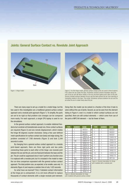
There are many ways to set up a model for a metal hinge, but the<br />
two used in this investigation are a traditional general surface contact<br />
approach and a revolute joint approach (Figure 1). To simplify, the parts<br />
are set to be rigid so that problem size changes can be compared<br />
more easily. For each approach, a single CPU laptop is used to run<br />
the simulations.<br />
In the general surface contact approach, to enable rotational freedoms<br />
but constrain all translationals except one, three contact surfaces<br />
are required (Figure 2) and one remote displacement, which rotates<br />
the hinge 90 degrees counter-clockwise. Using a few user-defined<br />
mesh specifications for surface contact size (body and edge sizing), the<br />
problem consisted of 7,188 elements (Figure 3) and took 2,249<br />
seconds to solve.<br />
By changing from a general surface contact approach to a revolute<br />
joint–based approach, there are three rigid parts and two joints<br />
connecting those parts to each other at the hinge: one revolute joint<br />
between the ear and the pin, and one fixed joint between the base and the<br />
pin. The pin could be suppressed since it won’t perform any function once<br />
it is replaced with a revolute joint, but it is included in the model to make<br />
the run-time comparison equivalent with the general surface contact<br />
approach. The total problem size, as expected, is far smaller, uses only 14<br />
elements (Figure 4) and requires a solution time of only 1.625 seconds.<br />
So what have we learned? First, if detailed contact information<br />
at the hinge pin is unimportant, it is a lot more efficient to replace<br />
thousands of contact elements with a single revolute joint element.<br />
PRODUCTS & TECHNOLOGY: MULTIBODY<br />
Figure 1. Hinge model Figure 2. For this hinge model, general surface contact joints are used in three locations.<br />
First, where the ear meets the base, frictionless surfaces prevent translation along the<br />
axis of the pin and still allow rotation of the ear and base against each other at the joint.<br />
Second, bonded surfaces between the pin and the base prevent the pin from spinning or<br />
translating relative to the base. Then lastly, frictionless surfaces between the ear and the<br />
pin allow the ear to rotate freely about the pin.<br />
Doing that, the model can be solved in a fraction of the time it took to<br />
solve without the use of joints. Second, as can be seen from the element<br />
listing in Figure 4, even in a model in which contact surfaces are not<br />
specified, there are still contact elements — which come from use of<br />
the joint or MPC184 element — but far fewer of them.<br />
TYPE NUMBER NAME<br />
1 1 MASS21<br />
2 1 MASS21<br />
3 1 MASS21<br />
4 1 CONTA176<br />
5 1 TARGE170<br />
6 180 CONTA174<br />
8 1 TARGE170<br />
9 178 CONTA174<br />
10 180 CONTA174<br />
11 178 TARGE170<br />
12 576 CONTA174<br />
13 1 CONTA176<br />
14 1 TARGE170<br />
15 832 CONTA174<br />
16 1408 CONTA174<br />
17 1408 TARGE170<br />
18 288 CONTA174<br />
19 832 CONTA174<br />
20 288 CONTA174<br />
21 832 TARGE170<br />
Figure 3. Element description for hinge<br />
joint modeled with general surface contact<br />
TYPE NUMBER NAME<br />
1 1 MASS21<br />
2 1 MASS21<br />
3 1 MASS21<br />
4 1 CONTA176<br />
5 1 TARGE170<br />
6 2 CONTA176<br />
7 1 TARGE170<br />
8 1 CONTA176<br />
9 1 TARGE170<br />
10 2 CONTA176<br />
11 1 TARGE170<br />
12 1 MPC184<br />
Figure 4. Element description for hinge<br />
joint modeled with a revolute joint<br />
www.ansys.com <strong>ANSYS</strong> Advantage • Volume II, Issue 2, 2008 21