Simulation - ANSYS
Simulation - ANSYS
Simulation - ANSYS

You also want an ePaper? Increase the reach of your titles
YUMPU automatically turns print PDFs into web optimized ePapers that Google loves.
TIPS & TRICKS<br />
Using New Meshing<br />
Features in <strong>ANSYS</strong><br />
Workbench <strong>Simulation</strong><br />
Knowing when and how to apply key features of the<br />
latest structural meshing tools can result in greater efficiency.<br />
By Sheldon Imaoka, Technical Support Engineer, <strong>ANSYS</strong>, Inc.<br />
As solvers become faster and computers more powerful,<br />
the solution portion of finite element analysis shortens and a<br />
larger portion of overall simulation time is spent on<br />
pre-processing, including generating the mesh — the fundamental<br />
element-based representation of parts to be<br />
analyzed. Recognizing this trend, <strong>ANSYS</strong>, Inc. has addressed<br />
the need for faster and more reliable structural meshing with<br />
new technologies in <strong>ANSYS</strong> Workbench <strong>Simulation</strong> 11.0 (also<br />
known as <strong>ANSYS</strong> Workbench Meshing 11.0). These new<br />
capabilities result in very robust meshing and save considerable<br />
amounts of time (especially for complex geometries)<br />
with features that automate many routine tasks while<br />
providing users high levels of control of their model.<br />
During the past several years, meshing in <strong>ANSYS</strong><br />
Workbench <strong>Simulation</strong> has not only grown to encompass<br />
typical meshing algorithms available in traditional structural<br />
software from <strong>ANSYS</strong> but has also included many features<br />
requested by its large base of users worldwide. This wealth<br />
of new meshing capabilities includes:<br />
• Physics-based meshing and element shape checking<br />
• Higher degree of mesh sizing controls<br />
• Patch independent surface and volume meshing<br />
• Flexible sweep and hexahedral meshing, including<br />
automated generation of SOLSH190 solid-shell<br />
elements<br />
Physics-Based Meshing and Element Shape Checking<br />
Traditionally, software from <strong>ANSYS</strong> requires users to<br />
select the appropriate element type first; meshing<br />
algorithms and conservative shape-checking criteria are<br />
typically independent of the physics of the problem. On the<br />
other hand, <strong>ANSYS</strong> Workbench <strong>Simulation</strong> provides users<br />
with the ability to set default global meshing options under<br />
the DETAILS view of the MESH branch that is dependent<br />
on the analysis physics.<br />
46<br />
<strong>ANSYS</strong> Advantage • Volume II, Issue 2, 2008<br />
The <strong>ANSYS</strong> Workbench platform can generate meshes<br />
for structural, thermal, electromagnetics, explicit dynamics<br />
or computational fluid dynamics (CFD) analyses, but the<br />
meshing considerations vary for each. For example, lowerorder<br />
elements with a finer mesh density tend to be used<br />
in CFD analyses, whereas higher-order elements with a<br />
coarser mesh density may be preferred in structural analyses.<br />
For each physics, different criteria are used for element<br />
shape checking to ensure that the elements provide accurate<br />
results for that particular analysis. For mechanical analysis<br />
users, STANDARD and AGGRESSIVE shape checking are<br />
also available. STANDARD shape checking is suitable for<br />
linear analyses, while AGGRESSIVE checking provides more<br />
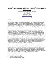
Figure 1. In an analysis of 2-D contact between gears, a SPHERE OF INFLUENCE<br />
(in red) is defined with a user-specified radius (left). This generates a fine mesh<br />
within this area for studying von Mises stresses at the point of tooth contact as well<br />
as within the geometry of the gear body (right).<br />
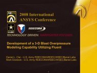
Figure 2. In modeling a fastener in a part (left), CONTACT SIZING is used to<br />
automatically create a fine mesh density in the area of initial contact. Section planes<br />
show the resulting detailed stress distribution inside the part (right), providing an<br />
optimal mesh in capturing contact behavior.<br />
www.ansys.com