Simulation - ANSYS
Simulation - ANSYS
Simulation - ANSYS

Create successful ePaper yourself
Turn your PDF publications into a flip-book with our unique Google optimized e-Paper software.
conservative element shape-checking criteria to account for<br />
possible distortion of the elements during nonlinear analyses.<br />
Higher Degree of Mesh Sizing Controls<br />
Mesh sizing controls are available in <strong>ANSYS</strong> Workbench<br />
<strong>Simulation</strong> under the MESH branch, allowing users to<br />
specify element size on vertices, edges, faces or bodies<br />
(parts), with number of divisions and mesh biasing<br />
available on edges. Two features introduced in <strong>ANSYS</strong><br />
Workbench <strong>Simulation</strong> 10.0 are SPHERE OF INFLUENCE<br />
and CONTACT SIZING.<br />
Under a surface or body mesh sizing branch, instead of<br />
specifying a uniform mesh density for the entire geometric<br />
entity, a user can use a defined COORDINATE SYSTEM<br />
and a radius to designate a sphere where elements will have<br />
a certain size. This is helpful in specifying a smaller mesh<br />
density without requiring existing geometry to identify that<br />
region. The sphere of influence mesh control is also useful in<br />
propagating a mesh density inside the geometry, rather than<br />
concentrating a finer mesh only on the surface of the model.<br />
In analyzing the stress distribution of 2-D contact between<br />
gears, for example, a user may create a sphere of influence<br />
to generate a fine mesh on the edges of the gear teeth as<br />
well as within the geometry of the gear body (Figure 1).<br />
Many users already know that contact regions are associated<br />
with the geometry in <strong>ANSYS</strong> Workbench <strong>Simulation</strong>,<br />
so remeshing an assembly does not require re-creating<br />
contact pairs. Another useful related feature is CONTACT<br />
SIZING, which allows users to define a more uniform,<br />
finer mesh density in a contact region to provide a better<br />
distribution of contact pressure. Instead of having users<br />
manually select surfaces on which to define element sizes,<br />
however, the CONTACT SIZING control allows users to<br />
specify mesh densities that are applied only in areas of<br />
initial contact for the defined contact regions. Thus, a user<br />
only has to drag-and-drop a contact region from the<br />
CONNECTIONS branch to the MESH branch and specify an<br />
element size — so only the actual areas that are in initial<br />
contact will have that finer mesh (Figure 2).<br />
Meshing and Defeaturing<br />
The default volume mesher in <strong>ANSYS</strong> Workbench<br />
<strong>Simulation</strong> automatically includes some defeaturing, unlike<br />
the mesher in traditional software from <strong>ANSYS</strong>, which<br />
meshes all surfaces, including any sliver areas present in the<br />
model. The user can control the percentage of defeaturing<br />
by specifying the DSMESH DEFEATUREPERCENT variable<br />
in the VARIABLE MANAGER located under the TOOLS<br />
menu. Consequently, instead of meshing small slivers<br />
(which would generate more nodes and elements), <strong>ANSYS</strong><br />
Workbench <strong>Simulation</strong> internally ignores these surfaces,<br />
providing a more robust, efficient mesh that requires little<br />
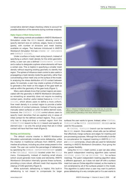
cleanup of CAD geometry (Figure 3).<br />
While automatic defeaturing is helpful, this built-in<br />
defeaturing is not meant to compensate for larger<br />
TIPS & TRICKS<br />
Figure 3. Instead of modeling the small sliver in this model (top), the automatic<br />
defeaturing capability in <strong>ANSYS</strong> Workbench <strong>Simulation</strong> intentionally ignores this<br />
surface (bottom) in generating a more robust, efficient mesh.<br />
surfaces the user wants to ignore. Instead, either VIRTUAL<br />
TOPOLOGY or the PATCH INDEPENDENT MESHER can be<br />
used for this purpose.<br />
A VIRTUAL TOPOLOGY branch can be inserted from<br />
the MODEL branch. Once added, virtual cells can be defined<br />
that effectively merge surfaces and edges for meshing and<br />
pre-processing purposes. Although the functionality is similar<br />
to concatenation for mapped meshing in <strong>ANSYS</strong> (ACCAT<br />
and LCCAT commands), virtual cells are used for tetrahedral<br />
meshing in <strong>ANSYS</strong> Workbench <strong>Simulation</strong>, thus giving the<br />
user greater flexibility.<br />
Using the METHOD mesh control, a user can also utilize<br />
the patch independent meshing algorithm (also named<br />
UNIFORM QUAD/TRI or UNIFORM TRI for surface<br />
meshing). The patch independent meshing algorithm takes<br />
a different approach, as it does not start off with a surface<br />
mesh but uses an Octree algorithm instead, so the mesher is<br />
not constrained by all of the surfaces present in the model.<br />
This algorithm is useful when a user may want to perform<br />
gross defeaturing of a very complex part or if a user wants to<br />
www.ansys.com <strong>ANSYS</strong> Advantage • Volume II, Issue 2, 2008 47