Simulation - ANSYS
Simulation - ANSYS
Simulation - ANSYS

You also want an ePaper? Increase the reach of your titles
YUMPU automatically turns print PDFs into web optimized ePapers that Google loves.
PRODUCTS & TECHNOLOGY: MULTIBODY<br />
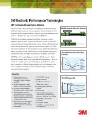
Angle=46.9715 Degrees<br />
Figure 5. Interactive joint manipulation is possible within the <strong>ANSYS</strong> Rigid Dynamics module, performed on a computer<br />
screen by using the mouse to move the model.<br />
<strong>ANSYS</strong> Rigid Dynamics<br />
The <strong>ANSYS</strong> Rigid Dynamics<br />
module, first released at Version 11.0,<br />
makes extensive use of joints for<br />
connecting parts. This is an <strong>ANSYS</strong><br />
Workbench add-on tool for users<br />
who have <strong>ANSYS</strong> Structural, <strong>ANSYS</strong><br />
Mechanical or <strong>ANSYS</strong> Multiphysics<br />
licenses. The module enhances the<br />
capability of those products by adding an<br />
explicit solver that is tuned for solving<br />
purely rigid assemblies. As a result, it is<br />
significantly faster than the implicit solver<br />
for purely rigid transient dynamic simulations.<br />
The <strong>ANSYS</strong> Rigid Dynamics<br />
module also has added interactive joint<br />
manipulation and <strong>ANSYS</strong> Workbench<br />
<strong>Simulation</strong> interface options.<br />
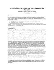
Figure 6. Folding arms of John Deere agricultural sprayer model to be subjected to time–history loading<br />
Image courtesy Brenden L. Stephens, John Deere<br />
Interactive joint manipulation allows<br />
the user to solve a model essentially in<br />
real time — the explicit solver produces<br />
a kinematic solution with part positions<br />
and velocities — using the mouse to<br />
displace the parts of the model.<br />
This tool is on the menu bar in the Connections<br />
folder. New Configure, Set and<br />
Revert buttons can be used to exercise<br />
a model that is connected via joints, set<br />
a configuration to use as a starting<br />
point or revert back to the original configuration<br />
as needed. In the case shown<br />
in Figure 5, before finding a solution, the<br />
hinge has been rotated a little more<br />
than 46 degrees to verify that the joint<br />
is, in fact, behaving like a hinge.<br />
The <strong>ANSYS</strong> Rigid Dynamics module<br />
is run using the same techniques<br />
that are used in <strong>ANSYS</strong> Workbench<br />
<strong>Simulation</strong> — attaching to the CAD or<br />
the <strong>ANSYS</strong> DesignModeler model,<br />
using the model tree, populating the<br />
Connections folder and inserting New<br />
Analysis, for example.<br />
The combination of the explicit<br />
Runge–Kutta time integration scheme<br />
and a dedicated rigid body formulation<br />
creates a product that while limited to<br />
working only with completely rigid parts,<br />
22<br />
22 <strong>ANSYS</strong> Advantage • Volume II, Issue 2, 2008<br />
www.ansys.com