Rigorous Sensor Modeling and Triangulation for OrbView-3 - asprs
Rigorous Sensor Modeling and Triangulation for OrbView-3 - asprs
Rigorous Sensor Modeling and Triangulation for OrbView-3 - asprs

You also want an ePaper? Increase the reach of your titles
YUMPU automatically turns print PDFs into web optimized ePapers that Google loves.
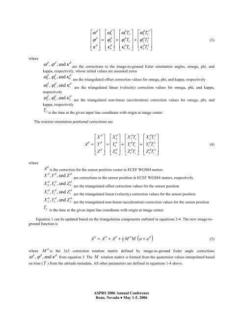
where<br />
where<br />
δ δ<br />
ω , ϕ , <strong>and</strong> κ<br />
δ<br />
δ δ δ<br />
δ 2<br />
⎡ω<br />
⎤ ⎡ω<br />
⎤ ⎡ ⎤ ⎡ ⎤<br />
0 ω1<br />
TC<br />
ω2TC<br />
⎢ δ ⎥ ⎢ δ ⎥ ⎢ δ ⎥ ⎢ δ 2 ⎥<br />
⎢ϕ<br />
⎥ = ⎢ϕ0<br />
⎥ + ⎢ϕ1<br />
TC<br />
⎥ + ⎢ϕ2<br />
TC<br />
⎥<br />
⎢ δ ⎥ ⎢ δ ⎥ ⎢ δ ⎥ ⎢ δ 2 ⎥<br />
⎣κ<br />
⎦ ⎣κ0<br />
⎦ ⎣κ1<br />
TC<br />
⎦ ⎣κ<br />
2TC<br />
⎦<br />
are the corrections to the image-to-ground Euler orientation angles, omega, phi, <strong>and</strong><br />
kappa, respectively, whose initial values are assumed zeros<br />
δ δ δ<br />
ω0 , ϕ0<br />
, <strong>and</strong> κ0<br />
are the triangulated offset correction values <strong>for</strong> omega, phi, <strong>and</strong> kappa, respectively<br />
δ δ δ<br />
ω1 , ϕ1<br />
, <strong>and</strong> κ1<br />
are the triangulated linear (velocity) correction values <strong>for</strong> omega, phi, <strong>and</strong> kappa,<br />
respectively<br />
δ δ δ<br />
ω2 , ϕ2<br />
, <strong>and</strong> κ2<br />
are the triangulated non-linear (acceleration) correction values <strong>for</strong> omega, phi, <strong>and</strong><br />
kappa, respectively<br />
TC is the time at the given input line coordinate with origin at image center.<br />
The exterior orientation positional corrections are<br />
A<br />
δ<br />
⎡X<br />
⎢<br />
= ⎢Y<br />
⎢<br />
⎣ Z<br />
δ<br />
δ<br />
δ<br />
δ δ<br />
δ 2<br />
⎤ ⎡X<br />
⎤ ⎡ ⎤ ⎡ ⎤<br />
0 X1<br />
Tc<br />
X 2Tc<br />
⎥ ⎢ δ ⎥ ⎢ δ ⎥ ⎢ δ 2 ⎥<br />
⎥ = ⎢Y0<br />
⎥ + ⎢Y1<br />
Tc<br />
⎥ + ⎢Y2<br />
Tc<br />
⎥<br />
⎥ ⎢ δ ⎥ ⎢ δ ⎥ ⎢ δ 2 ⎥<br />
⎦ ⎣ Z0<br />
⎦ ⎣ Z1<br />
Tc<br />
⎦ ⎣ Z2<br />
Tc<br />
⎦<br />
δ<br />
A is the correction <strong>for</strong> the sensor position vector in ECEF WGS84 meters<br />
δ δ<br />
δ<br />
X , Y , <strong>and</strong> Z<br />
are corrections to the sensor position in ECEF WGS84 meters, respectively<br />
δ δ<br />
δ<br />
X 0 , Y0<br />
, <strong>and</strong> Z0<br />
are the triangulated offset correction values <strong>for</strong> the sensor position<br />
δ δ<br />
δ<br />
X1<br />
, Y1<br />
, <strong>and</strong> Z1<br />
are the triangulated linear (velocity) correction values <strong>for</strong> the sensor position<br />
δ δ<br />
δ<br />
X 2 , Y2<br />
, <strong>and</strong> Z2<br />
are the triangulated non-linear (acceleration) correction values <strong>for</strong> the sensor position<br />
T C is the time at the given input line coordinate with origin at image center.<br />
Equation 1 can be updated based on the triangulation components outlined in equations 2-4. The new image-toground<br />
function is<br />
G O δ 1<br />
A = A + A + k<br />
M<br />
δ ( a + a )<br />
δ<br />
where M is the 3x3 correction rotation matrix defined by image-to-ground Euler angle corrections<br />
δ δ δ<br />
ω , ϕ , <strong>and</strong> κ from equation 3. The M rotation matrix is <strong>for</strong>med from the quaternion values interpolated based<br />
on time (T ) from the attitude metadata. All other parameters are defined in equations 1-4 above.<br />
ASPRS 2006 Annual Conference<br />
Reno, Nevada ♦ May 1-5, 2006<br />
δ<br />
M<br />
(3)<br />
(4)<br />
(5)