- Page 1 and 2: TopPage SAFETY PRECAUTION IMPORTANT
- Page 3 and 4: ii EIP-5000/5000L PRECAUTIONS A PRE
- Page 5 and 6: UV-RADIATION PRECAUTION (Continued)
- Page 7 and 8: Precautions for using lead-free sol
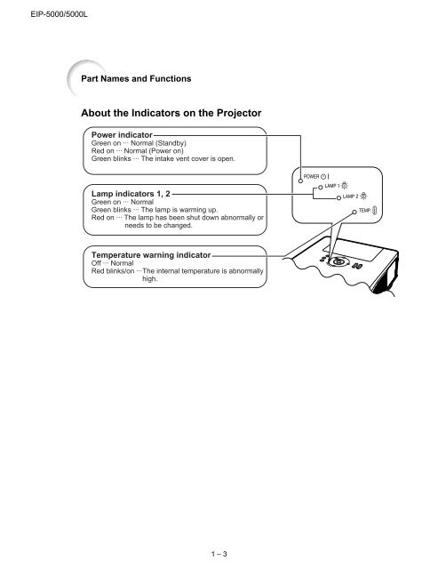
- Page 9: [2] Operation Manual Part Names and
- Page 13 and 14: Usable Range The remote control can
- Page 15 and 16: DVI digital Terminal (INPUT 3) 24 8
- Page 17 and 18: [4] Maintenance Indicators Maintena
- Page 19 and 20: [5] Regarding the Lamp Regarding th
- Page 21 and 22: Regarding the Lamp 4 Remove the lam
- Page 23 and 24: EIP-5000/5000L U/D CHAPTER 2. REMOV
- Page 25 and 26: [3] Removing the Lens Hood * For EI
- Page 27 and 28: [7] Removing the Top Cabinet 1. Rem
- Page 29 and 30: [9] Removing the PWB Units 1. Disco
- Page 31 and 32: 7. Remove the three screws from the
- Page 33 and 34: [12] Removing the Filter Unit 1. Di
- Page 35 and 36: EIP-5000/5000L U/D CHAPTER 3. ELECT
- Page 37 and 38: No. Adjusting point Adjusting condi
- Page 39 and 40: [4] SERVICE MODE 1. How to enter Se
- Page 41 and 42: 9. Network setting 10. Exit from se
- Page 43 and 44: EIP-5000/5000L U/D CHAPTER 4. TROUB
- Page 45 and 46: Check Video signal input. Go to "Ch
- Page 47 and 48: Checking the Main unit. Check outpu
- Page 49 and 50: Checking the Terminal unit. Check i
- Page 51 and 52: 1 2 3 Checking the RGB input Feed t
- Page 53 and 54: RGB signal check Is the Signal Type
- Page 55 and 56: 4 Component input (except 408i) che
- Page 57 and 58: VIDEO sync signal check Measure TL8
- Page 59 and 60: — MEMO — 4 - 17 EIP-5000/5000L
- Page 61 and 62:
k B+12VM B+5VM B+3V3AT IC26/27/ 28/
- Page 63 and 64:
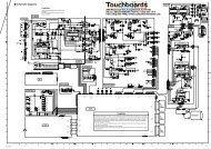
Overall wiring diagram ermal nsor D
- Page 65 and 66:
11 12 13 14 15 16 17 18 19 6 - 2 EI
- Page 67 and 68:
11 12 13 14 15 16 17 18 19 6 - 4 EI
- Page 69 and 70:
J I H G F E D C B A FORMATTER Unit
- Page 71 and 72:
J I H G F E D C B A POWER Unit (Sid
- Page 73 and 74:
J I H G F E D C B A FILTER Unit (Si
- Page 75 and 76:
J I H G F E D C B A PC I/F Unit (Si
- Page 77 and 78:
[7] AUDIO Unit J I H G F E D C B A
- Page 79 and 80:
J I H G F E D C B A KEYPAD Unit (Si
- Page 81 and 82:
[10] IR (FRONT)/IR (REAR)/LAMP1 COV
- Page 83 and 84:
EIP-5000/5000L U/D CHAPTER 8. SCHEM
- Page 85 and 86:
PartsGuide [1] PRINTED WIRING BOARD
- Page 87 and 88:
NO. PARTS CODE [2] 9NK5600600363 (M
- Page 89 and 90:
NO. PARTS CODE [2] 9NK5600600363 (M
- Page 91 and 92:
NO. PARTS CODE [2] 9NK5600600363 (M
- Page 93 and 94:
NO. PARTS CODE [2] 9NK5600600363 (M
- Page 95 and 96:
NO. PARTS CODE [2] 9NK5600600363 (M
- Page 97 and 98:
NO. PARTS CODE [2] 9NK5600600363 (M
- Page 99 and 100:
NO. PARTS CODE [2] 9NK5600600363 (M
- Page 101 and 102:
NO. PARTS CODE [3] 9NK5600600498 (F
- Page 103 and 104:
NO. PARTS CODE [4] 9NK5600204367 (P
- Page 105 and 106:
NO. PARTS CODE [5] 9NK5600204350 (F
- Page 107 and 108:
NO. PARTS CODE [6] 9NK5600600362 (P
- Page 109 and 110:
NO. PARTS CODE [6] 9NK5600600362 (P
- Page 111 and 112:
NO. PARTS CODE [6] 9NK5600600362 (P
- Page 113 and 114:
NO. PARTS CODE [6] 9NK5600600362 (P
- Page 115 and 116:
NO. PARTS CODE [9] 9NK5600204245 (P
- Page 117 and 118:
NO. PARTS CODE [11] 9NK5600204319 (
- Page 119 and 120:
NO. PARTS CODE [11] 9NK5600204319 (
- Page 121 and 122:
NO. PARTS CODE [14] 9NK5600204260 (
- Page 123 and 124:
[19] CABINET AND MECHANICAL PARTS (
- Page 125 and 126:
[21] CABINET AND MECHANICAL PARTS (
- Page 127 and 128:
NO. PARTS CODE [22] CABINET AND MEC
- Page 129 and 130:
NO. PARTS CODE [22] CABINET AND MEC
- Page 131 and 132:
NO. PARTS CODE [23] OPTICAL MECHANI
- Page 133 and 134:
[25] PACKING PARTS (NOT REPLACEMENT