CERN-THESIS-2012-153 26/07/2012 - CERN Document Server
CERN-THESIS-2012-153 26/07/2012 - CERN Document Server
CERN-THESIS-2012-153 26/07/2012 - CERN Document Server

You also want an ePaper? Increase the reach of your titles
YUMPU automatically turns print PDFs into web optimized ePapers that Google loves.
The positive x-direction is defined as pointing from the interaction point to the center of the LHC ring<br />
and the positive y-axis is defined as pointing upwards. The azimuthal angle, φ, is measured around the<br />
beam axis, and the polar angle θ is the angle from the beam axis. The pseudorapidity is defined as<br />
η ≡ −ln tan(θ/2). The distance between objects 1 and 2 in the pseudorapidity-azimuthal angle space,<br />
is defined as ∆R ≡ (φ1 − φ2) 2 + (η1 − η2) 2 . The transverse momentum, pT, is defined as psin θ, where p<br />
is the momentum. The transverse energy, ET, is defined as E sin θ, where E is the energy measured in the<br />
calorimeter, and θ is the polar angle of the energy deposition.<br />
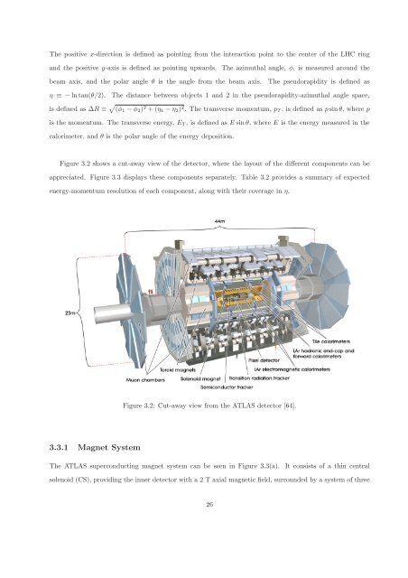
Figure 3.2 shows a cut-away view of the detector, where the layout of the different components can be<br />
appreciated. Figure 3.3 displays these components separately. Table 3.2 provides a summary of expected<br />
energy-momentum resolution of each component, along with their coverage in η.<br />
3.3.1 Magnet System<br />
Figure 3.2: Cut-away view from the ATLAS detector [64].<br />
The ATLAS superconducting magnet system can be seen in Figure 3.3(a). It consists of a thin central<br />
solenoid (CS), providing the inner detector with a 2 T axial magnetic field, surrounded by a system of three<br />
<strong>26</strong>