Operating Instructions Dplmagic Marker Dplgenesis ... - ACI Laser
Operating Instructions Dplmagic Marker Dplgenesis ... - ACI Laser
Operating Instructions Dplmagic Marker Dplgenesis ... - ACI Laser

Create successful ePaper yourself
Turn your PDF publications into a flip-book with our unique Google optimized e-Paper software.
Brief Description<br />
3.7.2 Connection<br />
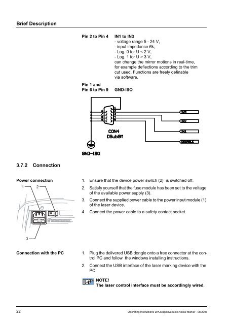
Pin 2 to Pin 4 IN1 to IN3<br />
- voltage range 5 - 24 V,<br />
- input impedance 6k,<br />
- Log. 0 for U < 2 V,<br />
- Log. 1 for U > 3 V,<br />
can change the mirror motions in real-time,<br />
for example deflections according to the trim<br />
cut used. Functions are freely definable<br />
via software.<br />
Pin 1 and<br />
Pin 6 to Pin 9 GND-ISO<br />
Power connection 1. Ensure that the device power switch (2) is switched off.<br />
1 2<br />
2. Satisfy yourself that the fuse module has been set to the voltage<br />
of the available power supply (3).<br />
3. Connect the supplied power cable to the power input module (1)<br />
of the laser device.<br />
4. Connect the power cable to a safety contact socket.<br />
3<br />
230 V<br />
Connection with the PC 1. Plug the delivered USB dongle onto a free connector at the control<br />
PC and follow the windows installing instructions.<br />
2. Connect the USB interface of the laser marking device with the<br />
PC.<br />
NOTE!<br />
The laser control interface must be accordingly wired.<br />
22 <strong>Operating</strong> <strong>Instructions</strong> DPLMagic/Genesis/Nexus <strong>Marker</strong> - 08/2006