Operating Instructions Dplmagic Marker Dplgenesis ... - ACI Laser
Operating Instructions Dplmagic Marker Dplgenesis ... - ACI Laser
Operating Instructions Dplmagic Marker Dplgenesis ... - ACI Laser

You also want an ePaper? Increase the reach of your titles
YUMPU automatically turns print PDFs into web optimized ePapers that Google loves.
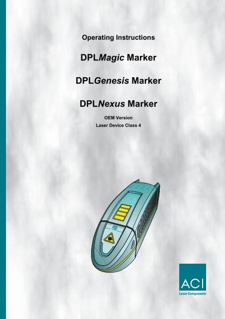
<strong>Operating</strong> <strong>Instructions</strong><br />
DPLMagic <strong>Marker</strong><br />
DPLGenesis <strong>Marker</strong><br />
DPLNexus <strong>Marker</strong><br />
OEM Version<br />
<strong>Laser</strong> Device Class 4
This product conforms to the requirements of the Machinery Directive 98/37/ EU<br />
(Machine regulations 9.GSGV). The CE symbol is located on the type plate.<br />
Manufacturer <strong>ACI</strong> <strong>Laser</strong> GmbH<br />
Österholzstraße 9<br />
D-99428 Nohra<br />
Germany<br />
Phone: +49 3643 4152-0<br />
Fax: +49 3643 4152-77<br />
Internet: www.<strong>ACI</strong>-<strong>Laser</strong>.de<br />
e-mail: info@<strong>ACI</strong>-<strong>Laser</strong>.de<br />
We are constantly working on further developments.<br />
Therefore, please understand that we must reserve the right to change the scope of the delivery in<br />
respect of the form, equipment and technology at any time.<br />
Reprinting, copying or translating this document in whole or in part is forbidden without the express<br />
written permission of <strong>ACI</strong> <strong>Laser</strong> GmbH!<br />
All rights under the copyright laws are expressly reserved by <strong>ACI</strong> <strong>Laser</strong> GmbH.<br />
The manufacturer shall only be responsible for the safety characteristics of this device within the<br />
scope of the legally applicable regulations if it is operated by the user in accordance with the<br />
operating instructions and repaired by <strong>ACI</strong> <strong>Laser</strong> GmbH itself or someone appointed by and acting<br />
under the instructions of <strong>ACI</strong> <strong>Laser</strong> GmbH.<br />
Last update: 08/2006<br />
© <strong>ACI</strong> <strong>Laser</strong> GmbH
Table of Contents<br />
1 Introduction ...................................................................................... 5<br />
2 Important Information...................................................................... 5<br />
2.1 Intended Use..................................................................................... 6<br />
2.2 Improper Use .................................................................................... 6<br />
2.3 Symbols in the Document ............................................................... 7<br />
Warning notes................................................................................ 7<br />
Additional symbols ......................................................................... 7<br />
Warning Notices on the Device...................................................... 8<br />
Type plate ...................................................................................... 9<br />
2.4 Basic Safety <strong>Instructions</strong> .............................................................. 10<br />
<strong>Laser</strong> class................................................................................... 10<br />
General Information ..................................................................... 11<br />
Initial operation............................................................................. 12<br />
Operation ..................................................................................... 12<br />
Maintenance/Care........................................................................ 12<br />
3 Brief Description ............................................................................ 13<br />
3.1 View of device ................................................................................ 13<br />
3.2 Intended purpose ........................................................................... 13<br />
3.3 Principle of Operation.................................................................... 14<br />
<strong>Laser</strong> beam source ...................................................................... 14<br />
Shutter ......................................................................................... 14<br />
Pilot laser ..................................................................................... 14<br />
Beam deflection ........................................................................... 14<br />
<strong>Laser</strong> electronics.......................................................................... 14<br />
3.4 Unpacking....................................................................................... 15<br />
Scope of delivery ......................................................................... 15<br />
3.5 Mechanical Installation.................................................................. 16<br />
Assembly ..................................................................................... 16<br />
Swivelling the scan unit................................................................ 16<br />
Focussing..................................................................................... 17<br />
3.6 Installing the Marking Software .................................................... 18<br />
Minimum hardware requirements ................................................ 18<br />
Installation.................................................................................... 18<br />
3.7 Electrical Installation ..................................................................... 19<br />
3.7.1 Interfaces ........................................................................................ 19<br />
<strong>Laser</strong> control interface ................................................................. 19<br />
Optional trim-module.................................................................... 21<br />
3.7.2 Connection ...................................................................................... 22<br />
Power connection ........................................................................ 22<br />
Connection with the PC ............................................................... 22<br />
<strong>Operating</strong> <strong>Instructions</strong> DPLMagic/Genesis/Nexus <strong>Marker</strong> -08/2006 1
Table of Contents<br />
4 Initial operation............................................................................... 23<br />
4.1 Checking the Installation............................................................... 23<br />
4.2 Starting the <strong>Laser</strong> Marking Device................................................ 24<br />
Control elements .......................................................................... 24<br />
Start.............................................................................................. 24<br />
5 Operation ........................................................................................ 25<br />
Multi function display.................................................................... 25<br />
6 Maintenance, Repair....................................................................... 26<br />
7 Care ................................................................................................. 26<br />
Cleaning the objective.................................................................. 26<br />
Cleaning the ventilation slits......................................................... 27<br />
8 Scrap Disposal ............................................................................... 28<br />
9 Fault Finding................................................................................... 29<br />
9.1 General Faults ................................................................................ 29<br />
9.2 Specific Faults ................................................................................ 30<br />
10 Technical Customer Service ......................................................... 32<br />
11 Warranty.......................................................................................... 32<br />
12 Technical Data ................................................................................ 33<br />
<strong>Laser</strong> device................................................................................. 33<br />
Connection values........................................................................ 33<br />
Fuse protection ............................................................................ 33<br />
Interfaces ..................................................................................... 33<br />
Scan unit ...................................................................................... 34<br />
Beam source dimensions incl. scanner........................................ 34<br />
Operation and Storage Conditions .............................................. 34<br />
13 Detailed Advanced Information..................................................... 35<br />
13.1 DPLMagic/Genesis/Nexus <strong>Marker</strong>, a highly integrated<br />
marking system .............................................................................. 35<br />
13.2 Design and function....................................................................... 35<br />
Preliminary remarks ..................................................................... 35<br />
Basic terminology......................................................................... 36<br />
13.2.1 <strong>Laser</strong> beam source .......................................................................... 37<br />
13.2.2 Q-switch .......................................................................................... 38<br />
Continuous wave mode (cw)........................................................ 38<br />
Pulse operation ........................................................................... 38<br />
13.2.3 Beam deflection ............................................................................... 38<br />
13.2.4 Plane field objective ........................................................................ 39<br />
Field correction............................................................................. 39<br />
2 <strong>Operating</strong> <strong>Instructions</strong> DPLMagic/Genesis/Nexus <strong>Marker</strong> - 08/2006
Table of Contents<br />
13.2.5 <strong>Laser</strong> Control ................................................................................... 40<br />
Power supply ............................................................................... 40<br />
Control system ............................................................................. 40<br />
Interfaces ..................................................................................... 40<br />
13.2.6 Marking Software ............................................................................ 41<br />
13.3 <strong>Laser</strong> beam quality......................................................................... 42<br />
Multimode laser............................................................................ 42<br />
DPLMagic/Genesis/Nexus <strong>Marker</strong>............................................... 42<br />
13.3.1 Pulse Power Density ....................................................................... 43<br />
Example 1 .................................................................................... 43<br />
Example 2 .................................................................................... 44<br />
Summary...................................................................................... 44<br />
13.4 Thermoelectric Air Cooling ........................................................... 44<br />
13.4.1 Design ............................................................................................. 44<br />
Principle of operation of a Peltier element ................................... 45<br />
13.4.2 Cooler Dimensioning ....................................................................... 45<br />
Cooling the laser diode ................................................................ 45<br />
Temperature stabilisation of the resonator .................................. 46<br />
13.5 The Materials Science of <strong>Laser</strong> Marking in Brief ........................ 46<br />
13.5.1 Pulse Overlapping ........................................................................... 47<br />
Example 1 .................................................................................... 47<br />
Example 2 .................................................................................... 47<br />
13.5.2 Marking Methods ............................................................................. 48<br />
Heating......................................................................................... 48<br />
Melting ......................................................................................... 48<br />
Vaporisation ................................................................................. 48<br />
Removal....................................................................................... 48<br />
13.5.3 Materials .......................................................................................... 48<br />
Metals .......................................................................................... 48<br />
Plastics......................................................................................... 49<br />
<strong>Laser</strong> foils..................................................................................... 49<br />
14 Appendix......................................................................................... 50<br />
14.1 Saturation vapour pressure as a function of the temperature .. 50<br />
14.2 Technical drawing.......................................................................... 51<br />
14.3 EG Declaration of Conformity....................................................... 52<br />
15 Index................................................................................................ 53<br />
<strong>Operating</strong> <strong>Instructions</strong> DPLMagic/Genesis/Nexus <strong>Marker</strong> -08/2006 3
Table of Contents<br />
4 <strong>Operating</strong> <strong>Instructions</strong> DPLMagic/Genesis/Nexus <strong>Marker</strong> - 08/2006
1 Introduction<br />
2 Important Information<br />
Introduction<br />
Dear customer,<br />
thank you for the confidence which you have shown in us by<br />
purchasing our quality product. We would like to wish you every<br />
success with the use of the device.<br />
Make yourself familiar with these operating instructions before<br />
starting use. The operating instructions tell you how to use your new<br />
device correctly and safely, and take you step by step through the<br />
actions which have to be performed before using it for the first time.<br />
Our Products are developed and manufactured under strict quality<br />
monitoring to give a long and fault-free service life.<br />
This guarantees:<br />
• highest quality and a long life,<br />
• easy and safe operation,<br />
• functional design,<br />
• optimisation for the intended purpose.<br />
The DPLMagic/Genesis/Nexus <strong>Marker</strong> is a state-of-the-art device.<br />
The Declaration of Conformity confirms that the manufacturer has<br />
complied with the relevant directives. The CE-symbol is located on<br />
the type plate.<br />
The laser marking device contains a class 4 laser according to DIN<br />
EN 60825-1 "Safety of <strong>Laser</strong> Devices“.<br />
Should the operating company integrate the device as an OEM<br />
component into an existing installation, it shall bear the sole<br />
responsibility for fulfilling the standards and directives. This<br />
includes, for example, fitting it into a laser protection hood or<br />
integrating it into a production line.<br />
The company operating the laser marking device is obliged to<br />
implement the safety measures arising from BGV B 2 "<strong>Laser</strong><br />
Irradiation" (formerly VBG 93) and from DIN EN 60825-1 "Safety of<br />
<strong>Laser</strong> Devices".<br />
Please read these operating instructions carefully from the<br />
beginning in order to avoid errors and risks.<br />
Reference is made to residual hazards at the relevant places in the<br />
operating instructions. Please also take note of the warning notice<br />
stickers on the device.<br />
<strong>Operating</strong> <strong>Instructions</strong> DPLMagic/Genesis/Nexus <strong>Marker</strong> -08/2006 5
Important Information<br />
2.1 Intended Use<br />
2.2 Improper Use<br />
• The operating company is obliged to appoint a laser safety officer<br />
in accordance with para. 6 of BGV B2 "<strong>Laser</strong> Irradiation" to ensure<br />
that the relevant safety guidelines and standards are observed.<br />
• The DPLMagic/Genesis/Nexus <strong>Marker</strong> laser marking system is<br />
intended to be used exclusively for marking applications in<br />
conjunction with the associated MagicMark software.<br />
The performance parameters must be adapted to suit the<br />
properties of the materials to be marked.<br />
• The laser marking device is intended for integration into<br />
installations or lines.<br />
Please contact the customer for information about other possible<br />
applications.<br />
• Usage for the intended purpose includes observance of these<br />
operating instructions, the instructions in the software manual and<br />
the warning stickers on the device.<br />
• The supplier/manufacturer shall not be liable for personal injury or<br />
material damage resulting from improper use of the laser itself or<br />
the safety devices.<br />
All other uses other than use for the intended purpose, including that<br />
with other control software, shall be deemed to be improper use.<br />
The laser marking device must not be used by:<br />
• Persons who have not read or understood these operating<br />
instructions,<br />
• Persons who have not been instructed in the proper operation,<br />
• Persons who are under the influence of alcohol and or drugs, or<br />
• Persons whose alertness is impaired by medicines or other<br />
influences.<br />
The laser marking device must not be used:<br />
• if the required protective devices have not been provided<br />
according to para. 4 of BGV B2 "<strong>Laser</strong> Irradiation“,<br />
• if protective/safety devices are bridged, defective or if they cannot<br />
reliably fulfil their function,<br />
• if there is a suspicion that direct or leakage radiation can emanate.<br />
6 <strong>Operating</strong> <strong>Instructions</strong> DPLMagic/Genesis/Nexus <strong>Marker</strong> - 08/2006
2.3 Symbols in the Document<br />
Warning notes Examples of warning notes:<br />
Important Information<br />
Take note of the warning notices, take the specified actions and<br />
observe the prohibitions.<br />
A warning notice warns of a possible hazard and contains<br />
recommendations for preventing the hazard occurring. Key words<br />
indicate the type of hazard, symbols emphasise this visually.<br />
Follow the stated measures for preventing hazards to the operator<br />
or tangible material assets.<br />
WARNING!<br />
Risk of fire/explosion! Do not mark any easily flammable<br />
or combustible materials.<br />
DANGER!<br />
Injury hazard from leakage radiation!<br />
Wear protective goggles!<br />
CAUTION!<br />
Possible property damage!<br />
Determine the condensation temperature!<br />
Condensation water may damage the device!<br />
Additional symbols NOTE!<br />
Useful additional information and tips!<br />
Protect the environment!<br />
<strong>Instructions</strong> for observing environmental protection<br />
regulations!<br />
<strong>Operating</strong> <strong>Instructions</strong> DPLMagic/Genesis/Nexus <strong>Marker</strong> -08/2006 7
Important Information<br />
Warning Notices on the<br />
Device<br />
1<br />
2<br />
The warning notices on the device point out possible hazards from<br />
the laser and provide information about the basic performance data<br />
of the laser units.<br />
• On the top of the enclosure<br />
(1)<br />
• On the beam outlet cover<br />
(2)<br />
DPLMagic <strong>Marker</strong> DPLGenesis <strong>Marker</strong> DPLNexus <strong>Marker</strong><br />
) 8 � 1, - : 2 � 5 7 4 - 6 � 4 ) , 1) 6 1� �<br />
- � 15 5 1� � � . 8 15 1* � - ) � ,<br />
1� 8 15 1* � - � ) 5 - 4 4 ) , 1) 6 1� �<br />
8 15 1* � - ) � , 1� 8 15 1* � -<br />
� ) 5 - 4 4 ) , 1) 6 1� �<br />
) 8 � 1, - : 2 � 5 7 4 - � . - ; - � 4 5 � 1� 6 �<br />
, 14 - + 6 � 4 5 + ) 6 6 - 4 - , 4 ) , 1) 6 1� �<br />
+ � ) 5 5 " � ) 5 - 4<br />
� ) : � 2 � 9 - 4 � # 9 �# � �<br />
2 7 � 5 , 7 4 ) 6 1� � � # � # � I<br />
9 ) 8 - � - � / 6 0 � $ " � �<br />
� � 4 � � - � $ & # �<br />
2 7 * � 1+ ) 6 1� �<br />
� ) : � 2 � 9 - 4 � � 9<br />
9 ) 8 - � - � / 6 0 � $ # � �<br />
� � 4 � � - � $ & # �<br />
2 7 * � 1+ ) 6 1� �<br />
) 8 � 1, - : 2 � 5 7 4 - 6 � 4 ) , 1) 6 1� �<br />
- � 15 5 1� � � . 8 15 1* � - ) � ,<br />
1� 8 15 1* � - � ) 5 - 4 4 ) , 1) 6 1� �<br />
8 15 1* � - ) � , 1� 8 15 1* � -<br />
� ) 5 - 4 4 ) , 1) 6 1� �<br />
) 8 � 1, - : 2 � 5 7 4 - � . - ; - � 4 5 � 1� 6 �<br />
, 14 - + 6 � 4 5 + ) 6 6 - 4 - , 4 ) , 1) 6 1� �<br />
+ � ) 5 5 " � ) 5 - 4<br />
� ) : � 2 � 9 - 4 � 9 � � �<br />
2 7 � 5 , 7 4 ) 6 1� � � # � # � I<br />
9 ) 8 - � - � / 6 0 � $ " � �<br />
� � 4 � � - � $ & # �<br />
2 7 * � 1+ ) 6 1� �<br />
� ) : � 2 � 9 - 4 � � 9<br />
9 ) 8 - � - � / 6 0 � $ # � �<br />
� � 4 � � - � $ & # �<br />
2 7 * � 1+ ) 6 1� �<br />
8 <strong>Operating</strong> <strong>Instructions</strong> DPLMagic/Genesis/Nexus <strong>Marker</strong> - 08/2006
Important Information<br />
Type plate The type plate (1) on the back of the laser marking device contains<br />
information about:<br />
• series number,<br />
• manufacturer,<br />
• date of manufacture<br />
• operating voltage/frequency range,<br />
• power consumption and<br />
• device fuse<br />
1<br />
<strong>Operating</strong> <strong>Instructions</strong> DPLMagic/Genesis/Nexus <strong>Marker</strong> -08/2006 9
Important Information<br />
2.4 Basic Safety <strong>Instructions</strong><br />
The following safety instructions have fundamental importance for<br />
the use of the laser marking device, and for its care and<br />
maintenance.<br />
They must always be followed and are only stated centrally here.<br />
<strong>Laser</strong> class As an OEM component, the DPLMagic/Genesis/Nexus <strong>Marker</strong> is a<br />
class 4 laser marking device according to DIN EN 60825-1 "Safety<br />
of <strong>Laser</strong> Devices“.<br />
• The accessible laser radiation is very dangerous to the eyes and<br />
skin.<br />
• Even diffuse, scattered laser radiation can be dangerous if the<br />
accessible radiation exceeds the class 1 threshold.<br />
• Improperly used laser radiation may lead to a risk of fire or<br />
explosion.<br />
The following measures must be taken in order to be able to<br />
categorise the DPLMagic/Genesis/Nexus <strong>Marker</strong> as a class 1 laser<br />
device (accessible laser radiation is harmless):<br />
• Ensure that the entire beam path to the work piece is shielded<br />
beam-tight.<br />
• Those parts of the screening which can be removed without tools<br />
must be fitted with safety switches which interrupt the beam path<br />
before the laser beam leaves the device.<br />
• Viewing windows (e.g. in the enclosure or the screening) must be<br />
fitted with laser protection glass appropriate for the wavelength<br />
and the laser power class.<br />
The guidelines stated in DIN EN 60825-1 "Safety of <strong>Laser</strong> Devices"<br />
and BGV B2 "<strong>Laser</strong> Irradiation" must be implemented if the<br />
accessible laser radiation cannot be reduced to below the class 1<br />
threshold values when the device is integrated into the installation.<br />
The laser safety officer can receive training from the customer. This<br />
training is recognised by the statutory industrial accident insurance<br />
institution.<br />
You will find other training opportunities under:<br />
www.lasersicherheit.de<br />
10 <strong>Operating</strong> <strong>Instructions</strong> DPLMagic/Genesis/Nexus <strong>Marker</strong> - 08/2006
Important Information<br />
General Information Take note of the following before each start up:<br />
• Do not transport, store or operate the device in a vertical position.<br />
There is a risk of damaging optical components.<br />
• Read the operating instructions and always keep them in an<br />
accessible place.<br />
• The ventilation slits must be clear and free of any residual packing<br />
material.<br />
• The ambient temperature must lie within the range of > 15 °C and<br />
< 35 °C. The condensation temperature as a function of the<br />
momentary relative air humidity must be < 20 °C. You will find an<br />
instruction for estimating the momentary value in the appendix.<br />
• Ensure that the relative air humidity does not exceed 85%.<br />
• Never start the device immediately after large temperature<br />
changes. Condensation water may damage the device.<br />
• If the design of the installation prevents the requirements for class<br />
1 laser devices being fulfilled, the area around the laser system<br />
must be protected by<br />
• adjustable walls,<br />
• light signals and<br />
• warning notices<br />
so that adequate notice is given of the danger before the area is<br />
entered.<br />
• Install a second emission warning light in the view of the operator.<br />
During operation, this signals that the beam catcher (shutter)<br />
arranged in the laser beam path is open.<br />
The shutter consists of a screen which can be swivelled into the<br />
beam path, so interrupting the laser process.<br />
• Chemical and physical reactions during the laser marking can<br />
cause<br />
• gases,<br />
• vapours,<br />
• aerosols,<br />
• dusts,<br />
• mists or<br />
• other reaction products<br />
to be given off from the material surface.<br />
These may be toxic, depending upon the material being<br />
processed.<br />
The operating company must therefore provide effective<br />
extraction. Information about this can be found, for example,<br />
in the VDI guideline 2262 1...3 "Air Quality in the Work Place“.<br />
<strong>Operating</strong> <strong>Instructions</strong> DPLMagic/Genesis/Nexus <strong>Marker</strong> -08/2006 11
Important Information<br />
Initial operation • Ensure that an adequate air supply can be provided at the<br />
installation site and that none of the ventilation slits are covered.<br />
• Mount the device at the installation site in accordance with the<br />
regulations.<br />
• Ensure that the shutter is active (closed) during the set up.<br />
The main beam is simulated by a class 2 pilot laser.<br />
The laser is not harmful to the skin. The eyes are protected by the<br />
natural blink reflex.<br />
Operation • The laser marking device may only be operated by trained<br />
personnel.<br />
It is advisable to log both the initial training as well as the regular<br />
refresher courses.<br />
• The device may only be operated when connected to an<br />
alternating voltage supply corresponding to the specifications on<br />
the type plate.<br />
• The effectiveness of the protective conductor must be regularly<br />
checked and confirmed by an authorised skilled worker.<br />
• If a defect occurs in the laser marking device, it must be<br />
disconnected from the power supply system and secured against<br />
being switched on again.<br />
Maintenance/Care • Maintenance and repair work on the laser device may only be<br />
performed by the manufacturer, the customer.<br />
• The device must be disconnected from the power supply system<br />
before the covers are removed.<br />
• Do not touch the electrical/electronic components. Capacitors<br />
could still be charged and so be under voltage.<br />
12 <strong>Operating</strong> <strong>Instructions</strong> DPLMagic/Genesis/Nexus <strong>Marker</strong> - 08/2006
3 Brief Description<br />
3.1 View of device<br />
1<br />
2<br />
3<br />
3.2 Intended purpose<br />
4<br />
5<br />
6<br />
7<br />
Brief Description<br />
The functional units of the laser marking device contain the following<br />
components:<br />
(1) <strong>Laser</strong> diode with thermoelectric air cooling,<br />
(2) Optical bank consisting of:<br />
lens system,<br />
resonator with laser crystal, mirror system, Q-switch and<br />
shutter (beam catcher),<br />
(3) Objective (laser beam outlet),<br />
(4) <strong>Laser</strong> electronics,<br />
(5) Galvanometer scan unit,<br />
(6) Multi-function-display,<br />
(7) Power input module and interfaces.<br />
The object of marking a work piece is to produce a marking with the<br />
following properties:<br />
• durability,<br />
• high contrast,<br />
• high resolution,<br />
• minimal stress on the material and<br />
• minimal change in its properties.<br />
These requirements are optimally fulfilled by the<br />
DPLMagic/Genesis/Nexus <strong>Marker</strong>.<br />
The laser marking device is a highly-integrated marking system.<br />
The components<br />
• optics,<br />
• control electronics,<br />
• thermoelectric air cooling<br />
are located in a compact functional unit.<br />
In contrast to other comparable systems, the DPLMagic/Genesis/<br />
Nexus <strong>Marker</strong> guarantees:<br />
• The easiest integration into existing production lines because of<br />
its small dimensions and low weight.<br />
• Increased operational safety by the elimination of external<br />
electrical and fiber-optic connections between the components.<br />
• Increased operational safety by the elimination of complex<br />
water-air-cooling units.<br />
• Minimising the down times and maintenance costs by replacing<br />
the complete functional unit during maintenance and service<br />
work.<br />
<strong>Operating</strong> <strong>Instructions</strong> DPLMagic/Genesis/Nexus <strong>Marker</strong> -08/2006 13
Brief Description<br />
3.3 Principle of Operation<br />
<strong>Laser</strong> beam source The laser beam source comprises a resonator for beam generation<br />
and amplification.<br />
The radiation of a laser diode (5) focused through a lens (1) excites<br />
1<br />
2 3 4<br />
a laser crystal (2). This, together with the following Q-switch (7), is<br />
positioned on the optical axis between the mirrors (6) and (8).<br />
The excited laser crystal (in this case a Nd:YAG) emits a continuous<br />
high-energy beam with a wavelength of 1064 nm.<br />
The laser beam is switched on and off with a pulse frequency (3) to<br />
1 Hz - 100 kHz by passing it through a Q-switch in order to achieve<br />
the energy density on the material to be marked that is required for<br />
the field of application. This achieves a power amplification of<br />
several orders of magnitude.<br />
5 6 7 8 A easily-focusable, pulsed laser beam (4) with an ideal energy<br />
distribution over its cross-section is available at the beam outlet.<br />
Shutter A swivelling screen is arranged in the resonator. The laser process<br />
is interrupted by closing the shutter.<br />
Pilot laser The wavelength of the working laser is not in the visible range. The<br />
light of a low power red laser diode is reflected into the beam path<br />
between the shutter and scanhead to check the marking window.<br />
This enables the positions of the marking window to be made visible<br />
when the shutter is closed.<br />
Beam deflection The focusing point of the laser beam has to be deflected in the x and<br />
y directions in order to mark greatly differing materials. This is<br />
achieved by the deflection units of a galvanometer scanner.<br />
Focusing is assisted by one of three alternative plane field<br />
objectives, whose focal length determines the size of the marking<br />
field and the spot diameter.<br />
<strong>Laser</strong> electronics The internal laser control monitors and regulates the entire process<br />
of beam generation and deflection. It communicates with the<br />
controlling PC via an USB interface.<br />
Its information and commands are evaluated and executed.<br />
The laser marking device has a laser control interface with active 24<br />
V I/O signals as an interface to external systems.<br />
14 <strong>Operating</strong> <strong>Instructions</strong> DPLMagic/Genesis/Nexus <strong>Marker</strong> - 08/2006
3.4 Unpacking<br />
Brief Description<br />
The laser marking device is delivered in a packaging which meets<br />
UPS "falling regulations".<br />
From the inside outwards:<br />
• DPLMagic/Genesis/Nexus laser device with the FireSCAN scan<br />
unit completely mounted,<br />
• foam grid,<br />
• vacuum-tight, welded aluminium foil with desiccant,<br />
• inner carton,<br />
• foam corners,<br />
• outer carton with accessories included in the scope of delivery.<br />
1. Open the carton on the top. Take note of the marking<br />
OBEN (TOP)!<br />
2. Remove the laser marking device in its packing material and put<br />
it down in a safe place.<br />
3. Open the foil packing and pull it off.<br />
4. Remove the foam grid from the device.<br />
5. Place the device on a flat surface.<br />
6. Remove the accessories and place them down.<br />
7. Check the scope of delivery for completeness.<br />
NOTE!<br />
Store the packaging material in a safe place in case the<br />
device has to be returned to the manufacturer under<br />
warranty for maintenance and repair work.<br />
In such a case repack the laser marking device into its original<br />
packaging in the reverse order and seal it securely.<br />
Scope of delivery • The DPLMagic/Genesis/Nexus laser device and the FireSCAN<br />
scan unit completely mounted,<br />
• Power cable,<br />
• Connection cable for USB 2.0,<br />
• CD-ROM with Marking software,<br />
• <strong>Operating</strong> instructions,<br />
• Software manual,<br />
• Software dongle.<br />
NOTE!<br />
Check that the delivery is complete and undamaged.<br />
Please contact our service department if you have any<br />
queries.<br />
<strong>Operating</strong> <strong>Instructions</strong> DPLMagic/Genesis/Nexus <strong>Marker</strong> -08/2006 15
Brief Description<br />
3.5 Mechanical Installation<br />
CAUTION!<br />
Risk of damaging the objective!<br />
Leave the protective cover on the objective throughout<br />
the entire installation.<br />
Assembly A mounting surface (1) is provided on the underside of the device to<br />
enable it to be mechanically integrated into a system.<br />
The position of the bore holes (measured in mm) for<br />
451<br />
• 8 x M6 fixing screws (3) with washers/ tooth lock washers<br />
80 • 4 x alignment pins (2) ø6 H7<br />
± 0,1<br />
can be seen in the drawing on the left.<br />
For the attachment four screws and two pins are used at a time.<br />
NOTE!<br />
The above-mentioned standard parts are not included in<br />
the scope of delivery.<br />
Take note of the maximum screw depth of 8 mm.<br />
The length of the bearing surface on the system side should be at<br />
least 100 mm.<br />
NOTE!<br />
The manufacturer recommends fitting in a horizontal<br />
position as the scan unit can be swivelled through<br />
± (90° + 10°) from the basic vertical position if<br />
necessary.<br />
Swivelling the scan unit 1. Loosen the fixing screw (2) of the clamp ring (1).<br />
10°<br />
82,5<br />
25 ± 0,1<br />
80 ± 0,1<br />
1 2 3<br />
90°<br />
1 2<br />
3 4<br />
90°<br />
50 ± 0,1<br />
10°<br />
CAUTION!<br />
Risk of damaging the cable harness!<br />
Avoid the damage of the cable harness when rotating<br />
the scan unit.<br />
2. Rotate the scan unit (3) through the permissible swivelling<br />
range (4).<br />
3. Lock the scan unit by hand-tightening the fixing screw (2).<br />
16 <strong>Operating</strong> <strong>Instructions</strong> DPLMagic/Genesis/Nexus <strong>Marker</strong> - 08/2006
Brief Description<br />
Focussing NOTE!<br />
A defined distance between the objective of the<br />
scanhead and the work piece must be set in order to<br />
focus the laser beam optimally on the surface of the<br />
work piece.<br />
A<br />
1<br />
2<br />
3<br />
The distance (A) between the lower edge of the scan unit (2) and the<br />
surface of the workpiece (1) depends upon the type of objective<br />
used:<br />
• F-Theta 100: A = 142 ± 3 mm,<br />
• F-Theta 163: A = 220 ± 3 mm,<br />
• F-Theta 254: A = 400 ± 5 mm.<br />
The availability of a suitable height adjustment (3) is a useful aid<br />
when focusing.<br />
WARNING!<br />
Hazards of injury to personnel or damage to property!<br />
All safety-related devices must be installed and their<br />
effectiveness proven before the system is started up.<br />
The acceptance must be performed by the laser safety<br />
officer and recorded in writing.<br />
For safety reasons, the laser must not be activated until<br />
all the above-mentioned conditions have been fulfilled.<br />
<strong>Operating</strong> <strong>Instructions</strong> DPLMagic/Genesis/Nexus <strong>Marker</strong> -08/2006 17
Brief Description<br />
3.6 Installing the Marking Software<br />
Minimum hardware<br />
requirements<br />
Installation 1. Start your PC.<br />
• IBM-compatible Pentium 4 PC > 2 GHz,<br />
• Windows 2000/XP operating system,<br />
• 512 MB main memory,<br />
• 100 MB free hard disk capacity,<br />
• CD ROM drive,<br />
• 2 free USB 2.0 interfaces (for the device and for the dongle),<br />
• monitor (recommendation: 17 inch),<br />
• keyboard, mouse.<br />
2. Ensure that one of the above-mentioned operating systems is<br />
installed on your PC.<br />
3. Place the CD labelled MagicMark into the CD drive.<br />
4. Open the directory MagicMark in Explorer with a double click.<br />
5. Start the setup.exe by double-clicking.<br />
6. Follow the instructions of the installation program.<br />
The following message appears when the installation has been<br />
completed:<br />
Setup Complete.<br />
7. Confirm this by pressing the ENTER key.<br />
8. Start your PC again.<br />
NOTE!<br />
You find detailed references to the configuration of the<br />
marking system in the software manual.<br />
18 <strong>Operating</strong> <strong>Instructions</strong> DPLMagic/Genesis/Nexus <strong>Marker</strong> - 08/2006
3.7 Electrical Installation<br />
3.7.1 Interfaces<br />
1 2 3 4<br />
5 6<br />
Brief Description<br />
The interfaces are located on the back above the laser diode<br />
module.<br />
• The power input module (1) with integrated power switch and<br />
drawer for fine fuses.,<br />
• Power switch (2),<br />
• USB 2.0 interface (6),<br />
for communication between control PC and laser marking device,<br />
• <strong>Laser</strong> control interface (5), 37-pin, sub-D, panel socket<br />
as an interface to the plant/line.<br />
• Optional trim-module,<br />
potential-free inputs - CON3 (3) and<br />
potential-free inputs - CON4 (4).<br />
<strong>Laser</strong> control interface The <strong>Laser</strong> control interface is realised by a 37-pin, sub-D, panel<br />
socket, two-rowed.<br />
Depending upon the application case, the laser control interface<br />
1<br />
20 may be wired by the user.<br />
2<br />
3<br />
4<br />
5<br />
6<br />
7<br />
8<br />
9<br />
10<br />
11<br />
12<br />
13<br />
14<br />
15<br />
16<br />
17<br />
18<br />
19<br />
21<br />
22<br />
23<br />
24<br />
25<br />
26<br />
27<br />
28<br />
29<br />
30<br />
31<br />
32<br />
33<br />
34<br />
35<br />
36<br />
37<br />
WARNING!<br />
Hazard for persons and property.<br />
The laser control interface may only be connected to the<br />
plant by an electrician in cooperation with a laser safety<br />
officer.<br />
CAUTION!<br />
Only use safety switches authorised by the Customer.<br />
The external switches and signals are essential for complying with<br />
the laser protection regulations according to DIN EN 60825-1.<br />
Safety circuit - Chamber Interlock<br />
Pin 1, Pin 20 INTLOCK1, INTLOCK2<br />
External interlock circuit<br />
A potential-free safety switch must be wired between pin 1 and pin<br />
20 to integrate the shutter into an external safety circuit.<br />
Opening the switch sends a signal to the software and switches off<br />
the supply voltage to the shutter locking magnets.<br />
This swivels the shutter into the beam path and interrupts the laser<br />
process.<br />
When the switch is closed, the shutter can be opened by software.<br />
<strong>Operating</strong> <strong>Instructions</strong> DPLMagic/Genesis/Nexus <strong>Marker</strong> -08/2006 19
Brief Description<br />
External emission light<br />
Pin 22 EMISSION<br />
24 V, max. 200 mA, protected by polyfuse.<br />
Pin 22 carries 24 V when the shutter is open.<br />
The connected emission warning light signals:<br />
CAUTION!<br />
<strong>Laser</strong> radiation!<br />
Wiring this output is specified for operation in accordance with a<br />
class 4 laser.<br />
Emission ready<br />
Pin 3 READY<br />
24 V, max. 200 mA, protected by polyfuse.<br />
This output produces a composite signal of all possible error states.<br />
The output is set when all components function within normal<br />
parameters and the laser is ready for operation.<br />
This signal can be processed both optically and electronically.<br />
This output is an essential aid, particularly for use in production<br />
lines.<br />
Inputs and outputs<br />
Pin 5 to 12 IN1 to IN8<br />
24 V, 3.5 mA<br />
Control inputs for the PLC connector<br />
Pin 23 to 30 OUT1 to OUT8<br />
24 V, max. 0.5 A<br />
electronically secured, short-circuit-proof,<br />
Inductive loads may be connected.<br />
There is an internal freewheel diode.<br />
Pin 2, 4, 21 GND I/O<br />
Reference points for all 24 V inputs and outputs<br />
as well as READY and EMISSION<br />
The inputs can be queried during a marking cycle and so start e.g.<br />
a marking job. The freely programmable outputs can, for example,<br />
be used to indicate the end of an inscription.<br />
Please refer to the software manual for information concerning the<br />
processing of signals by the marking software.<br />
CAUTION!<br />
Current limitation: the maximum permissible current is<br />
the same for all outputs, all outputs are switched off if<br />
0.55 A is exceeded (see page 30 Overload I/O.)<br />
20 <strong>Operating</strong> <strong>Instructions</strong> DPLMagic/Genesis/Nexus <strong>Marker</strong> - 08/2006
Brief Description<br />
Connections for optional encoders (Marking on the fly)<br />
Pin 13, Pin 31 A1+, A1-<br />
Pin 14, Pin 32 B1+, B1-<br />
Pin 15, Pin 33 I1+, I1-<br />
Differential encoder inputs for 1.5 V level<br />
Pin 16, Pin 34 A2+, A2-<br />
Pin 17, Pin 35 B2+, B2-<br />
Pin 18, Pin 36 I2+, I2-<br />
Differential encoder inputs for 2.5 V level.<br />
Pin 19, Pin 37 5V EXT, GND EXT<br />
Encoder power supply, 5 V,<br />
max. 100 mA, protected by polyfuse,<br />
The supply voltage is switched<br />
on by software.<br />
Optional trim-module CON3 - potential-free inputs (open collector)<br />
9-pin, sub-D, panel socket, two-rowed<br />
Pin 1 GATE<br />
Lowside switch, max. 30 V, max. 25 mA,<br />
Blanking signal synchronous with laser pulses.<br />
Pin 2 to Pin 4 OUT1 to OUT3<br />
High-speed outputs synchronous<br />
with mirror motions and pulse generation,<br />
functions are freely definable via software.<br />
Pin 5 to Pin 9 GND-ISO<br />
CON4 - potential-free inputs<br />
9-pin, sub-D, panel plug, two-rowed.<br />
Pin 5 DISABLE<br />
Stops laser pulses in realtime.<br />
<strong>Operating</strong> <strong>Instructions</strong> DPLMagic/Genesis/Nexus <strong>Marker</strong> -08/2006 21
Brief Description<br />
3.7.2 Connection<br />
Pin 2 to Pin 4 IN1 to IN3<br />
- voltage range 5 - 24 V,<br />
- input impedance 6k,<br />
- Log. 0 for U < 2 V,<br />
- Log. 1 for U > 3 V,<br />
can change the mirror motions in real-time,<br />
for example deflections according to the trim<br />
cut used. Functions are freely definable<br />
via software.<br />
Pin 1 and<br />
Pin 6 to Pin 9 GND-ISO<br />
Power connection 1. Ensure that the device power switch (2) is switched off.<br />
1 2<br />
2. Satisfy yourself that the fuse module has been set to the voltage<br />
of the available power supply (3).<br />
3. Connect the supplied power cable to the power input module (1)<br />
of the laser device.<br />
4. Connect the power cable to a safety contact socket.<br />
3<br />
230 V<br />
Connection with the PC 1. Plug the delivered USB dongle onto a free connector at the control<br />
PC and follow the windows installing instructions.<br />
2. Connect the USB interface of the laser marking device with the<br />
PC.<br />
NOTE!<br />
The laser control interface must be accordingly wired.<br />
22 <strong>Operating</strong> <strong>Instructions</strong> DPLMagic/Genesis/Nexus <strong>Marker</strong> - 08/2006
4 Initial operation<br />
4.1 Checking the Installation<br />
Initial operation<br />
CAUTION!<br />
Possible property damage! Perform the following tests<br />
to avoid material damage.<br />
Please check the following points again before you start your laser<br />
system:<br />
• Have the mechanical and electrical installations been performed<br />
correctly and completely?<br />
• Does the fuse for the device correspond to the available operating<br />
voltage (110 V: 5 A, 2 x or 220 V: 2.5 A, 2 x)?<br />
• Have you removed the protective cover from the focusing<br />
objective?<br />
• Is the focusing objective clean and dust-free?<br />
• Do the environmental conditions meet the requirements<br />
(temperature, air humidity)?<br />
• Are all the ventilation slits open?<br />
• Is there an adequate fresh air supply to the laser device?<br />
• Are you familiar with the essential laser protection regulations?<br />
Have all the laser safety measures been taken?<br />
• Has the laser safety officer accepted the installation?<br />
<strong>Operating</strong> <strong>Instructions</strong> DPLMagic/Genesis/Nexus <strong>Marker</strong> -08/2006 23
Initial operation<br />
4.2 Starting the <strong>Laser</strong> Marking Device<br />
Control elements The laser marking system just has a power switch (1) beside the<br />
power input module.<br />
1<br />
It is operated via the marking software.<br />
Start 1. Start the control PC.<br />
NOTE!<br />
Keep to the switching sequence on each start.<br />
2. Wait until the operating system has completely loaded.<br />
3. Switch on the device power switch.<br />
Follow the windows installing instructions when starting up for<br />
the first time.<br />
The main power pack supplies the supply voltages required.<br />
The laser is not yet ready for operation.<br />
4. Start the marking software.<br />
The laser and scanner control, and the galvanometer are then<br />
initialised.<br />
NOTE!<br />
The marking software starts in demo mode if it is not<br />
possible to communicate with the laser marking device.<br />
The same happens if the software is started before the<br />
marking device.<br />
You find detailed advanced information in the software<br />
manual.<br />
24 <strong>Operating</strong> <strong>Instructions</strong> DPLMagic/Genesis/Nexus <strong>Marker</strong> - 08/2006
5 Operation<br />
Operation<br />
All operating sequences are controlled from the control PC via the<br />
laser control interface.<br />
All the parameters are exclusively entered on the keyboard of the<br />
control computer.<br />
NOTE!<br />
Detailed information for using the marking software is<br />
contained in the software manual provided.<br />
Multi function display On the multi-function-display (1) the current working state of the laser<br />
marking device is to be seen.<br />
1<br />
Display State Meaning<br />
Dark blue Offline Device switched on<br />
Software not started or no<br />
communication<br />
Dark-straw Off Communication exists,<br />
laser not activated<br />
Dark green with pale<br />
yellow flash<br />
On<br />
(not ready)<br />
Dark-green On<br />
(ready)<br />
Dark green with pale<br />
yellow light running<br />
down on both sides<br />
<strong>Laser</strong> activated,<br />
not ready for operation<br />
<strong>Laser</strong> activated,<br />
ready for operation<br />
Emission Device operates<br />
Light-yellow flashing Warning Warning<br />
but the device continues to<br />
operate<br />
Bright red flashing Error Fault,<br />
device deactivated,<br />
all power levels switched off<br />
electronically,<br />
see Fault Finding<br />
<strong>Operating</strong> <strong>Instructions</strong> DPLMagic/Genesis/Nexus <strong>Marker</strong> -08/2006 25
Maintenance, Repair<br />
6 Maintenance, Repair<br />
7 Care<br />
The laser device does not contain any parts which can be<br />
maintained or repaired by the user.<br />
All maintenance and repair work must be performed exclusively by<br />
the customer.<br />
The right to claim under warranty is lost as soon as third parties work<br />
on or modify the device.<br />
The customer has suitable test benches and routines to maintain<br />
your laser system optimally.<br />
CAUTION!<br />
Possible property damage!<br />
During the warranty period, use the original packaging<br />
exclusively when dispatching the defective device.<br />
Perform the following care activities on the device at regular<br />
intervals:<br />
• cleaning the objective,<br />
• cleaning the ventilation slits in the cover.<br />
WARNING!<br />
Hazards of injury to personnel or damage to property!<br />
Ensure that the power plug has been pulled out before<br />
starting the care tasks.<br />
Cleaning the objective A dirty objective reduces the transmission of the laser radiation. This<br />
leads to a reduction of the laser power on the work piece. The dirt<br />
can burn into the surface and damage the focusing objective. A<br />
protecting glass is therefore fixed in front of the objective by means<br />
of a threaded ring.<br />
NOTE!<br />
The warranty does not cover any damage caused by<br />
inadequate or improper cleaning.<br />
Make a regular visual inspection of the focusing objective/protecting<br />
glass. Clean the protecting glass if any dirt is found (and the<br />
objective if necessary). Only cleansers which are authorised for<br />
high-quality optics may be used for this purpose:<br />
• Never attempt to remove particles of dirt from the surface with<br />
compressed air.<br />
• Use a suitable lens cleaning paper and ethanol of optical purity<br />
standard.<br />
• Moisten one side of the cleaning paper. Do not touch the moist<br />
side under any circumstances.<br />
• Draw the cleaning paper slowly over the protective glass/focusing<br />
26 <strong>Operating</strong> <strong>Instructions</strong> DPLMagic/Genesis/Nexus <strong>Marker</strong> - 08/2006
Care<br />
objective. In so doing, draw the cloth in one direction only.<br />
• Remove any ethanol residue with a dry lens cleaning paper if<br />
necessary.<br />
• Repeat the procedure until the surface is completely clean. Use a<br />
new cleaning paper each time.<br />
NOTE!<br />
Suitable cleansers can be obtained from the<br />
manufacturer.<br />
Cleaning the ventilation slits Cleaning the ventilation slits regularly is a prerequisite for faultless<br />
operation of the device. Clean the ventilation slits as follows:<br />
1<br />
1. Remove the two fixing screws (1) from the back of the laser device<br />
and the four screws (2) from the bottom.<br />
2<br />
3<br />
4<br />
5<br />
4<br />
230 V<br />
2. Pull the rear cover off the device.<br />
3. Remove the two rear screws (3) of the center cover.<br />
4. Loosen the screw (4) holding the clamping ring of the scan unit<br />
and turn the scan unit to the side or remove it.<br />
Ensure that the connecting cable is not damaged or jammed.<br />
5. Remove the two front screws (5) of the center cover.<br />
6. Remove the center cover.<br />
7. Clean the ventilation slits in the covers with a dry or slightly<br />
damp cloth.<br />
Do not use any solvent for cleaning them.<br />
8. Ensure that the covers are completely dry before reclosing the<br />
device.<br />
9. Reassemble the covers in the reverse order.<br />
NOTE!<br />
Slide the cover onto the device into position.<br />
Screw the fixing screws in hand tight.<br />
10. Check the electrical connections before bringing the device<br />
back into operation.<br />
<strong>Operating</strong> <strong>Instructions</strong> DPLMagic/Genesis/Nexus <strong>Marker</strong> -08/2006 27
Scrap Disposal<br />
8 Scrap Disposal<br />
ENVIRONMENTAL PROTECTION!<br />
For a small fee, the customer will accept return of the<br />
laser device and dispose of it properly in a manner that<br />
is environmentally compatible.<br />
Environmentally sensible disposal of electrical and electronic<br />
equipment!<br />
Electrical and electronic equipment contains valuable materials that<br />
should be supplied to recycling or recovery.<br />
Please dispose of electrical and electronic equipment at qualified<br />
collecting points separate from municipal waste.<br />
28 <strong>Operating</strong> <strong>Instructions</strong> DPLMagic/Genesis/Nexus <strong>Marker</strong> - 08/2006
9 Fault Finding<br />
9.1 General Faults<br />
Problem/Fault Possible cause Elimination<br />
Error message when<br />
loading the<br />
marking software<br />
Marking software<br />
incorrectly installed<br />
USB cable not connected<br />
properly<br />
<strong>Laser</strong> will not start USB cable not connected<br />
properly<br />
Reinstall the software.<br />
Fault Finding<br />
Check whether the cable is plugged in correctly.<br />
No supply voltage Check whether your laser is supplied with<br />
power.<br />
Check whether the cable is plugged in correctly.<br />
No laser beam Shutter closed Check whether all safety switches are locked.<br />
Check whether the shutter is opened in your<br />
marking job.<br />
Defocusing Check the focus position by changing the distance<br />
between focusing objective and work<br />
piece.<br />
Incorrect laser<br />
parameters<br />
Check your laser parameters, they may not<br />
be suitable for the work piece to be marked.<br />
<strong>Laser</strong> power too low Defocusing Check the focus position by changing the distance<br />
between focusing objective and work<br />
piece.<br />
Incorrect laser<br />
parameters<br />
<strong>Laser</strong> does not pulse Incorrect laser<br />
parameters<br />
<strong>Laser</strong> switches off automatically<br />
Environmental conditions<br />
do not meet the<br />
specifications<br />
Check your laser parameters, they may not<br />
be suitable for the work piece to be marked.<br />
Check the laser parameter settings, the laser<br />
may be working in cw operation.<br />
Check the environmental conditions.<br />
Keep to the environmental conditions<br />
required.<br />
NOTE!<br />
Please contact our Technical Customer Service in the<br />
first instance if the fault cannot be eliminated as<br />
described above.<br />
<strong>Operating</strong> <strong>Instructions</strong> DPLMagic/Genesis/Nexus <strong>Marker</strong> -08/2006 29
Fault Finding<br />
9.2 Specific Faults<br />
The MagicMark marking software monitors the laser device for<br />
possible faults and provides the user with status messages about<br />
the state of individual system components.<br />
The messages are displayed in the system windows Messages on<br />
the monitor.<br />
Status/Error Trigger Message<br />
Break_NTC_DiodeDrv DiodeDrv Break Sensor LD<br />
Driver<br />
Evaluation per<br />
Software<br />
Display + Cut Off<br />
Overcurrent_<strong>Laser</strong>diode DiodeDrv Overcurrent LD Display + Cut Off<br />
Overtemp_Diode-Driver DiodeDrv Overtemp LD-Driver Display + Cut Off<br />
5V Error,
Status/Error Trigger Message<br />
LoopStatus_<strong>Laser</strong>Crystal TempCtrl Crystal Temp <strong>Laser</strong> OOR Display<br />
LoopStatus_<strong>Laser</strong>Crystal<br />
> Limit 1 (10 Min.)<br />
LoopStatus_<strong>Laser</strong>Crystal<br />
> Limit 2 (20 Min.)<br />
Fault Finding<br />
TempCtrl Crystal Temp <strong>Laser</strong> OOR1 Display + Cut Off<br />
TempCtrl Crystal Temp <strong>Laser</strong> OOR2 Display<br />
Break Sensor Crystal TempCtrl Crystal Break Sensor Crystal Display + Cut Off<br />
Break TE Diode TempCtrl Diode Break TE Diode Display + Cut Off<br />
LoopStatus_<strong>Laser</strong>Diode TempCtrl Diode Temp Diode OOR Display<br />
LoopStatus_<strong>Laser</strong>Diode<br />
> Limit 1 (10 Min.)<br />
LoopStatus_<strong>Laser</strong>Diode<br />
> Limit 2 (20 Min.)<br />
TempCtrl Diode Temp Diode OOR1 Display + Cut Off<br />
TempCtrl Diode Temp Diode OOR2 Display<br />
Evaluation per<br />
Software<br />
Overtemp_Diode TempCtrl Diode Overtemp Diode Display + Cut Off<br />
Break Sensor Diode TempCtrl Diode Break Sensor Diode Display + Cut Off<br />
An overview of the possible messages and their meaning can be<br />
found in the software manual.<br />
<strong>Operating</strong> <strong>Instructions</strong> DPLMagic/Genesis/Nexus <strong>Marker</strong> -08/2006 31
Technical Customer Service<br />
10 Technical Customer Service<br />
11 Warranty<br />
<strong>ACI</strong> <strong>Laser</strong> GmbH<br />
Österholzstraße 9<br />
D-99428 Nohra<br />
Deutschland<br />
Phone: +49 3643 4152-0<br />
Fax: +49 3643 4152-77<br />
Internet: www.<strong>ACI</strong>-<strong>Laser</strong>.de<br />
email: service@<strong>ACI</strong>-<strong>Laser</strong>.de<br />
NOTE!<br />
The laser device may only be maintained and repaired<br />
by the manufacturer. Any manipulations on the device<br />
or breaking the warranty seal will void any claims under<br />
warranty.<br />
The customer guarantees that the product does not have any<br />
manufacturing or material defects.<br />
The warranty period shall be 12 months from the dispatch date in as<br />
far as no other contractual ruling has been made.<br />
The scope of warranty is limited to the repair or replacement of the<br />
product supplied by the customer.<br />
The customer is responsible for returning repairs under warranty to<br />
the customer, the customer is responsible for returning the device to<br />
the customer.<br />
The customer does not accept any liability under warranty<br />
• if the product has been damaged by incorrect handling or<br />
operation, or as a result of improper use,<br />
• if seals on the device have been broken,<br />
• for damage caused by use under unauthorised environmental<br />
conditions,<br />
• for damage to the device if it is not returned in its original<br />
packaging,<br />
• for consequential damage.<br />
32 <strong>Operating</strong> <strong>Instructions</strong> DPLMagic/Genesis/Nexus <strong>Marker</strong> - 08/2006
12 Technical Data<br />
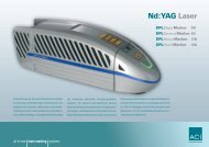
<strong>Laser</strong> device Diode pumped, actively Q-switched solid-state laser<br />
Technical Data<br />
<strong>Laser</strong> material: Nd:YAG<br />
Wave length: 1064 nm<br />
<strong>Laser</strong> power: DPLMagic <strong>Marker</strong> 5 W<br />
DPLGenesis <strong>Marker</strong> 8 W<br />
DPLNexus <strong>Marker</strong> 12 W<br />
Pulse train frequency: 1 - 100 kHz<br />
Pilot laser: 650 nm, 1 mW<br />
<strong>Laser</strong> class: 4<br />
Connection values Power supply:<br />
Power consumption<br />
100 - 240 VAC / 6 A / 50 - 60 Hz<br />
(typical): DPLMagic <strong>Marker</strong> 200 W<br />
DPLGenesis <strong>Marker</strong> 250 W<br />
Power consumption<br />
DPLNexus <strong>Marker</strong> 300 W<br />
(max.): DPLMagic <strong>Marker</strong> 450 W<br />
DPLGenesis <strong>Marker</strong> 550 W<br />
DPLNexus <strong>Marker</strong> 600 W<br />
Fuse protection 110 VAC: 2 x 5 AT<br />
220 VAC: 2 x 2.5 AT<br />
Interfaces Power supply: 3-pin socket with fine-wire fuse<br />
PC interface:<br />
<strong>Laser</strong> control<br />
USB 2.0<br />
interface for: - Chamber Interlock<br />
- External emission light<br />
- Signal Ready<br />
- 8 freely programmable in-/outputs<br />
- optional connections for encoder<br />
- optional trim-interface<br />
<strong>Operating</strong> <strong>Instructions</strong> DPLMagic/Genesis/Nexus <strong>Marker</strong> -08/2006 33
Technical Data<br />
Scan unit Galvanometer scanner:FireSCAN<br />
Aperture: 10 mm<br />
Scanning speed: < 5 m/sec<br />
Beam source dimensions incl.<br />
scanner<br />
Operation and Storage<br />
Conditions<br />
Focusing objectives, optional:<br />
F-Theta 100<br />
Spot diameter (1) : 25 µm<br />
Marking field size: 60 x 60 mm<br />
Focusing length: 142 ± 3 mm from lower edge of scan unit<br />
F-Theta 163<br />
Spot diameter (1) : 35 µm<br />
Marking field size: 110 x 110 mm<br />
Focusing length: 220 ± 3 mm from lower edge of scan unit<br />
F-Theta 254<br />
Spot diameter (1) : 50 µm<br />
Marking field size: 180 x 180 mm<br />
Focusing length: 400 ± 5 mm from lower edge of scan unit<br />
(1) Deviations may occur with different materials.<br />
Length x width x height:740 x 201 x 233 mm<br />
Weight: 20 kg<br />
<strong>Operating</strong> temperature: 25 °C ± 10 °C<br />
Storage temperature: 10 °C to 50 °C<br />
Air humidity: maximum 85%, non-condensing,<br />
non-corroding<br />
34 <strong>Operating</strong> <strong>Instructions</strong> DPLMagic/Genesis/Nexus <strong>Marker</strong> - 08/2006
13 Detailed Advanced Information<br />
Detailed Advanced Information<br />
13.1 DPLMagic/Genesis/Nexus <strong>Marker</strong>, a highly integrated marking system<br />
13.2 Design and function<br />
Highly integrated means that the laser consists of only one<br />
component. The components<br />
• optics,<br />
• control electronics and<br />
• thermoelectric air cooling<br />
are combined in a single casing.<br />
External power units, external laser diode pump modules and<br />
external water-air cooling units are now definitely things of the past.<br />
The advantages are obvious:<br />
• Integration into existing production lines has been made much<br />
easier as dimensions of e. g. only 740 x 201 x 233 mm reduce the<br />
space requirement and the total weight is 20 kg.<br />
• Operational safety has been increased by eliminating electrical<br />
and fiber-optic connections.<br />
• Complex water-air cooling units have been eliminated.<br />
• A unique service concept has been set up. The complete unit is<br />
exchanged during maintenance work thus minimisinged down<br />
times and maintenance costs.<br />
Preliminary remarks The object of all laser marking is to produce high contrast markings<br />
on many different types of materials. Various marking processes<br />
can be selected by varying the pulse power density.<br />
These include:<br />
• <strong>Laser</strong> engraving (erosion by vaporising the<br />
base material),<br />
• Vaporising the covering layers,<br />
• Colour changes produced by chemical reactions in the material.<br />
The contrast is optimised by adapting the most important laser<br />
parameters to the material to be marked.<br />
These include:<br />
• laser beam quality,<br />
• pulse length,<br />
• cw output and peak pulse power density,<br />
• pulse train frequency,<br />
• vector velocity.<br />
<strong>Operating</strong> <strong>Instructions</strong> DPLMagic/Genesis/Nexus <strong>Marker</strong> -08/2006 35
Detailed Advanced Information<br />
Basic terminology The most important terms have been briefly stated and described in<br />
the following in order to aid understanding of the complex physical<br />
interactions involved in the generation of a laser beam.<br />
• <strong>Laser</strong>:<br />
Light Amplification by Stimulated Emission of Radiation.<br />
E<br />
E<br />
• TEM oo - Mode, basic mode:<br />
The power distribution over the cross-section corresponds to a<br />
Gaussian function. The highest power occurs in the centre of the<br />
laser beam. The laser beam can be optimally focused.<br />
• Multimode:<br />
The power distribution across the beam cross-section is random.<br />
Multimode laser beam sources cannot be well focused.<br />
• Mode diaphragm:<br />
A mode diaphragm corresponds to an apertured diaphragm,<br />
which cuts off the outer part of the laser radiation. The laser beam<br />
quality is increased, but the laser power is substantially reduced.<br />
• Beam parameter product SF:<br />
Product of the divergence angle of the laser beam and the beam<br />
diameter at the laser outlet.<br />
The focusability of the laser beam improves as the SF falls.<br />
• Pulse length:<br />
The pulse length is another characteristic parameter of a Qswitched<br />
laser beam source. Depending upon the resonator<br />
structure, typical pulse lengths between 100 and 200 ns are<br />
achieved in the marking system’s field of application.<br />
The pulse length has a crucial influence on the peak pulse power<br />
which can be achieved on the surface of the material, and thus on<br />
the performance capability of the laser marker.<br />
The DPLMagic/Genesis/Nexus <strong>Marker</strong> achieves pulse lengths<br />
between ca. 20 and 50 ns. This enables the available cw laser<br />
power to be combined into extremely short pulses.<br />
The chronological reduction of the pulse lengths enables the cw<br />
power to be reduced while the peak pulse power remains<br />
constant.<br />
• Pulse width dt:<br />
As a rule, the pulse width does not designate the length of a laser<br />
pulse but rather the opening time of the Q-switch. This gives the<br />
user the opportunity of treating the material with continuous laser<br />
radiation after a laser shot.<br />
• cw laser power:<br />
... This is the average continuous power output by the laser.<br />
In the case of the DPL Magic/Genesis/Nexus <strong>Marker</strong> , this is at<br />
least 3/8/12 W in the basic mode.<br />
36 <strong>Operating</strong> <strong>Instructions</strong> DPLMagic/Genesis/Nexus <strong>Marker</strong> - 08/2006
13.2.1 <strong>Laser</strong> beam source<br />
1<br />
E[ev]<br />
E 4<br />
E 3<br />
E 2<br />
E 1<br />
2<br />
5<br />
3<br />
6<br />
4<br />
7<br />
= 1064 nm<br />
l<br />
8<br />
Detailed Advanced Information<br />
• Pulse train frequency:<br />
The pulse train frequency is the number of laser pulses per<br />
second.<br />
• Vector velocity:<br />
Velocity with which the laser beam is deflected in the x-y direction.<br />
The pulse width, cw laser power, pulse frequency and vector<br />
velocity are parameters which can be varied by the user. These<br />
parameters can be selected with the aid of the MagicMARK marking<br />
software according to the material and the desired marking effect.<br />
For marking, the laser beam is positioned and focused on the work<br />
piece to be marked by the FireSCAN mirror deflection unit and a<br />
plane field lens.<br />
The laser is controlled and monitored from the MagicMARK marking<br />
software.<br />
The laser beam source consists of an optical resonator for beam<br />
generation and amplification.<br />
The resonator contains the excitation source consisting of laser<br />
diode (5) and convergent lens (1), two mirrors (6, 8), the active laser<br />
medium (2 and the Q-switch (7) arranged on an optical axis.<br />
Ions or electrons in the active medium are brought to a higher<br />
energy level by the excitation source (pumping). The optical energy<br />
of the laser diodes is used for the excitation.<br />
An Nd:YAG (yttrium-aluminium-garnet) laser crystal which is doped<br />
with Nd 3+ ions is used in the DPLMagic/Genesis/Nexus <strong>Marker</strong>.<br />
The energy level schema of the Nd 3+ ions permits four possible<br />
energy levels. They are referred to as E1 to E4. Supplying the<br />
excitation energy raises the Nd 3+ ion from the basic state E1 to the<br />
E4 state. The Nd 3+ ion tries to return to the basic state E1. In so<br />
doing, it passes through the intermediate energy levels E3 and E2<br />
into the basic state E1. The transition from level E3 into level E2<br />
results in the spontaneous emission of light at a wavelength of 1064<br />
nm. The transitions E4-E3 and E2-E1 are to the greatest extent<br />
without radiation.<br />
<strong>Operating</strong> <strong>Instructions</strong> DPLMagic/Genesis/Nexus <strong>Marker</strong> -08/2006 37
Detailed Advanced Information<br />
13.2.2 Q-switch<br />
The laser is equipped with an active Q-switch to amplify its power.<br />
This enables the continuous power of the laser to be amplified by<br />
several orders of magnitude.<br />
The optical axis runs centrally through the Q-switch). If energy is<br />
supplied via the laser diode to the amplifier medium (Nd:YAG) and<br />
if the Q-switch is closed, all possible upper energy levels of the laser<br />
crystal are occupied. The laser process builds up like an avalanche<br />
if the Q-switch is now quickly opened. A laser pulse is generated, the<br />
power of which corresponds to the peak pulse power. The Q-switch<br />
is opened and closed by applying and interrupting a high-frequency<br />
voltage.<br />
Continuous wave mode (cw) If there is no high-frequency voltage at the Q-switch transducer, then<br />
the photons generated in the amplifier medium can pass unhindered<br />
through the Q-switch between the two laser mirrors.<br />
Pulse operation If a high-frequency voltage is applied to the Q-switch, this produces<br />
a very high loss which interrupts the stimulated emission.<br />
High-energy laser pulses are released by switching the high<br />
frequency on and off at a pulse frequency.<br />
This pulse frequency may be freely selected within the range of 1<br />
kHz to 100 kHz. It is set via the marking software. The frequency is<br />
selected according to the work piece material. Practical working<br />
frequencies lie in the range of 1 kHz to 35 kHz.<br />
13.2.3 Beam deflection<br />
For marking purposes, the laser beam has to be deflected onto the<br />
material within a working window which is freely selectable within<br />
certain limits.<br />
The laser beam is deflected by a mirror system. The mirrors are<br />
arranged so that one mirror covers the x-axis and the other mirror<br />
the y-axis. This enables every point in the marking field to be<br />
reached. The deflection units used are galvanometer scanners.<br />
38 <strong>Operating</strong> <strong>Instructions</strong> DPLMagic/Genesis/Nexus <strong>Marker</strong> - 08/2006
13.2.4 Plane field objective<br />
Detailed Advanced Information<br />
The size of the marking field is determined by the selection of a<br />
suitable objective.<br />
Three objective sizes are offered for the DPLMagic/Genesis/Nexus<br />
<strong>Marker</strong>:<br />
F-THETA 100<br />
Size of marking field: 60 x 60 mm<br />
Spot diameter: 25 µm<br />
F-THETA 163<br />
Size of marking field: 110 x 110 mm<br />
Spot diameter: 35 µm<br />
F-THETA 254<br />
Size of marking field: 180 x 180 mm<br />
Spot diameter: 50 µm<br />
After positioning the laser beam with the aid of the galvanometer<br />
scanning unit, it is focused on the work piece by a plane field<br />
objective.<br />
Using this objective brings the entire marking level into focus.<br />
Field correction The special arrangement of the galvanometer mirror and the<br />
properties of the plane field objective distort the marking image.<br />
A field correction therefore has to be made. This is done by predistorting<br />
the control signals for the galvanometer.<br />
The distortion is system-specific and is therefore individually defined<br />
in your marking software.<br />
<strong>Operating</strong> <strong>Instructions</strong> DPLMagic/Genesis/Nexus <strong>Marker</strong> -08/2006 39
Detailed Advanced Information<br />
13.2.5 <strong>Laser</strong> Control<br />
Power supply The operating voltages required for beam generation, the control<br />
system and the laser control interface are generated by a switched<br />
mode power supply. The input voltage range<br />
100 - 240 V AC at 50/60 Hz which this can achieve enables the<br />
DPLMagic/Genesis/Nexus <strong>Marker</strong> to be ready for immediate<br />
operation worldwide.<br />
The low power consumption of < 300 W contributes to reducing the<br />
operating costs and protecting the environment.<br />
Control system The laser control (USB laser control) monitors and controls the<br />
entire laser process. Over a bus system it links the components:<br />
• HF driver,<br />
• laser diode driver,<br />
• TE driver (laser diode),<br />
• TE driver (resonator),<br />
• laser interface.<br />
The laser control communicates with the controlling PC via the<br />
USB 2.0 interface.<br />
All the information and commands required for the operation of the<br />
laser pass to the laser control in this manner. The data are evaluated<br />
and the appropriate responses produced in the device.<br />
Interfaces As the interface to external systems, the laser marking device has a<br />
laser control interface with active 24 V I/O signals.<br />
40 <strong>Operating</strong> <strong>Instructions</strong> DPLMagic/Genesis/Nexus <strong>Marker</strong> - 08/2006
13.2.6 Marking Software<br />
Detailed Advanced Information<br />
All the laser’s functions are controlled from the Windows-oriented<br />
MagicMark marking software.<br />
This includes both control functions such as laser power, frequency,<br />
velocity etc., and data transmission of the actual marking content.<br />
The most important functions of the marking software are:<br />
• Sequence control:<br />
• laser On/Off,<br />
• shutter On/Off,<br />
• subroutines,<br />
• communication with external devices,<br />
• handling,<br />
• links to host.<br />
• Setting laser parameters:<br />
• power,<br />
• frequency.<br />
• Setting galvanometer parameters:<br />
• delays,<br />
• speed.<br />
• Character set selection:<br />
• fonts,<br />
• barcodes.<br />
• Text formatting commands:<br />
• left and right justified, centred,<br />
• arc.<br />
• Text content:<br />
• serial numbers,<br />
• fixed texts.<br />
• Graphics:<br />
The laser works vector-oriented.<br />
The user should be aware of this when creating the marking jobs<br />
and when selecting the laser parameters.<br />
The marking sequence may affect the total marking time. The user<br />
should avoid large jumps between the end and starting points of<br />
characters and/or graphic elements.<br />
Please refer to your software manual for further information about<br />
the marking software.<br />
<strong>Operating</strong> <strong>Instructions</strong> DPLMagic/Genesis/Nexus <strong>Marker</strong> -08/2006 41
Detailed Advanced Information<br />
13.3 <strong>Laser</strong> beam quality<br />
The laser beam quality is a system constant of the laser beam<br />
source. It is a measure of the quality of the laser radiation.<br />
The laser beam quality is a function of the design of the laser. The<br />
so-called beam parameter product SF is used as a measure of the<br />
beam quality.<br />
The smaller the beam parameter product SF, the better the laser<br />
beam can be focused.<br />
The energy distribution over the cross-section of the laser beam is<br />
equally important for the beam quality.<br />
A basic operating mode (TEM oo) of the laser in which the energy<br />
distribution corresponds to a Gaussian function is ideal.<br />
In this case, the divergence of the laser is particularly small and the<br />
beam can be very well focused.<br />
Multimode laser Conventional laser beam sources emit a multimode beam. The<br />
energy is distributed randomly over the beam cross-section.<br />
The beam quality of multimode lasers can only be increased by<br />
using aperture or mode diaphragms.<br />
The diaphragms frequently reduce the power to 10% of the<br />
multimode power. In so doing, a TEM oo mode is only approximately<br />
achieved.<br />
The beam parameter product SF for the multimode laser is calculated<br />
according to the following formula:<br />
DPLMagic/Genesis/Nexus<br />
<strong>Marker</strong><br />
SF TEMxx = ϕ TEMxx · d m<br />
with SF Beam parameter product<br />
ϕ Divergence<br />
d Beam diameter<br />
The diode-pumped DPLMagic/Genesis/Nexus <strong>Marker</strong> laser system<br />
achieves direct generation of the basic mode by means of an<br />
ingenious resonator concept which eliminates the need for mode<br />
diaphragms. This guarantees the highest possible beam quality and<br />
the best focus.<br />
This provides the basic conditions for achieving the above average,<br />
high efficiency of the compact marker.<br />
The beam parameter product SF for the DPLMagic/Genesis/Nexus<br />
<strong>Marker</strong> is calculated according to the following formula:<br />
SF TEMoo = ϕ TEMoo · d o = λ / π<br />
with SF Beam parameter product<br />
ϕ Divergence<br />
d Beam diameter<br />
λ Wave length 1064 nm<br />
42 <strong>Operating</strong> <strong>Instructions</strong> DPLMagic/Genesis/Nexus <strong>Marker</strong> - 08/2006
13.3.1 Pulse Power Density<br />
Detailed Advanced Information<br />
The pulse power density provides a measure of the actual<br />
performance capability of a laser marker.<br />
It is a function of the<br />
• pulse frequency,<br />
• pulse length and,<br />
• beam radius<br />
in the focus.<br />
The following applies:<br />
PP = ———<br />
f · dt<br />
with PP Pcw f<br />
pulse power<br />
continuous power<br />
pulse train frequency<br />
dt pulse duration<br />
and:<br />
P Pd = ———<br />
with P Pd pulse power density<br />
r beam radius in the focus<br />
Example 1 DPLMagic/Genesis/Nexus <strong>Marker</strong>,<br />
Basic mode TEMoo Starting values:<br />
Pcw = 3 W<br />
f = 2000 Hz<br />
dt = 30 ns<br />
r = 17.5 · 10 -6 m<br />
This gives:<br />
and:<br />
5 W<br />
PP = —————————— = 83,333 W<br />
P Pd = —————————— = 8.65 · 10 13 Wm -2<br />
<strong>Operating</strong> <strong>Instructions</strong> DPLMagic/Genesis/Nexus <strong>Marker</strong> -08/2006 43<br />
P cw<br />
P P<br />
r 2 · π<br />
2000 s -1 · 30 · 10 -9 s<br />
83,333 W<br />
(17.5 · 10 -6 m) 2 · π
Detailed Advanced Information<br />
Example 2 Conventional, diode-pumped marking laser,<br />
multimode<br />
Starting values:<br />
Pcw = 40 W<br />
f = 2000 Hz<br />
dt = 100 ns<br />
r = 35 · 10 -6 m<br />
This gives:<br />
and:<br />
40 W<br />
PP = —————————— = 200,000 W<br />
P Pd = —————————— = 5.19 · 10 13 Wm -2<br />
Summary It can be seen that the pulse power density on the material is higher<br />
with the DPL Magic/Genesis/Nexus <strong>Marker</strong> than with conventional,<br />
diode-pumped marking lasers in multimode operation.<br />
It does not rise linearly with the value of the continuous power.<br />
13.4 Thermoelectric Air Cooling<br />
13.4.1 Design<br />
2000 s -1 · 100 · 10 -9 s<br />
200,000 W<br />
(35 · 10 -6 m) 2 · π<br />
The design of the laser with the realisation of the highest peak pulse<br />
powers at low cw power enables the required pump output of the<br />
laser diode to be substantially reduced. This means that the heat<br />
generated and the dissipation power at the laser diode module are<br />
very low.<br />
The dissipation power which is turned into heat in the DPLMagic/<br />
Genesis/Nexus <strong>Marker</strong> is about 25 W. This means that this<br />
important characteristic is substantially lower in comparison to<br />
conventional diode-pumped laser marking systems.<br />
For cooling and stabilising the temperature of the laser diode, the<br />
DPLMagic/Genesis/Nexus <strong>Marker</strong> can therefore do without a waterair<br />
cooling system without impairing the performance capability of<br />
the cooling. Modern thermoelectric air cooling by means of Peltier<br />
elements is used instead.<br />
44 <strong>Operating</strong> <strong>Instructions</strong> DPLMagic/Genesis/Nexus <strong>Marker</strong> - 08/2006
Principle of operation of a<br />
Peltier element<br />
13.4.2 Cooler Dimensioning<br />
Detailed Advanced Information<br />
Peltier, the French physicist, discovered in 1834 the effect that the<br />
temperature falls below the ambient temperature when current flows<br />
at the contact point of two touching metals. The efficiency of this<br />
effect has been increased enormously over the last few years by the<br />
use of modern semiconductor materials.<br />
A Peltier element consists of an n- and a p-conducting<br />
semiconductor leg. These legs are linked by a copper bridge.<br />
If a direct current flows through such an element, one side of the<br />
element cools and thus takes heat energy from the environment.<br />
This heat energy is then released again to the environment or a heat<br />
sink on the other side. The direction of the heat flow is reversed by<br />
changing the direction of the current.<br />
A high cooling capacity is achieved by combining several Peltier<br />
elements in a Peltier block. The individual elements are connected<br />
electrically in series and thermally in parallel.<br />
Cooling the laser diode The following boundary conditions apply to the dimensions of the<br />
cooler for the DPLMagic/Genesis/Nexus <strong>Marker</strong>:<br />
• minimum cold side temperature<br />
on the laser diode: Tk = 20 °C,<br />
• maximum dissipation power<br />
of the laser diode: Pv = 25 W,<br />
• maximum permissible<br />
ambient temperature: Tu = 35 °C.<br />
A cooler unit which fulfils these requirements is integrated into the<br />
DPLMagic/Genesis/Nexus <strong>Marker</strong>. A constant cold side<br />
temperature is maintained at the laser diode at an ambient<br />
temperature of<br />
T u = 35 °C with simultaneous full load operation of the laser (P v = 25<br />
W). This requires the use of high performance Peltier blocks. Two<br />
Peltier blocks, each with 127 Peltier elements are used thermally in<br />
parallel for cooling the laser diode.<br />
The waste heat thus taken away from the laser diode is transferred<br />
to an aluminium cooler and released to the environmental air by<br />
means of a high performance fan.<br />
The dimensioning of the aluminium cooler (surface, volume etc.),<br />
the selection of a suitable fan and the implementation of optimal<br />
heat transmissions play a key role here. The thermal resistance,<br />
characteristic of the cooler module are determined to<br />
Rth < 0.1 K/W.<br />
<strong>Operating</strong> <strong>Instructions</strong> DPLMagic/Genesis/Nexus <strong>Marker</strong> -08/2006 45
Detailed Advanced Information<br />
Temperature stabilisation of<br />
the resonator<br />
The stability of the laser in respect of power and beam quality is<br />
especially important for the reproducibility of inscriptions. The<br />
DPLMagic/Genesis/Nexus <strong>Marker</strong> has therefore been equipped<br />
with temperature stabilisation of the active laser medium. This<br />
guarantees first class marking results even with very different power<br />
settings or even after the laser has been on stand-by for a long time.<br />
The temperature stabilisation of the laser crystal clearly reduced the<br />
formation of the so-called "thermal lens".<br />
This temperature stabilisation is also realised via a thermoelectric<br />
module. As the resonator is very efficient, the module requires<br />
significantly less power. The waste heat is conveyed out by means<br />
of a fan.<br />
13.5 The Materials Science of <strong>Laser</strong> Marking in Brief<br />
The question of whether a material is suitable for laser marking can<br />
generally be answered with yes, provided that it adequately absorbs<br />
the processing wavelength, this is 1064 nm in the case of the<br />
DPLMagic/Genesis/Nexus <strong>Marker</strong>.<br />
Complex interactions take place between the laser beam and the<br />
work piece during the marking procedure.<br />
The workability of a material depends upon the following material<br />
properties, among others:<br />
• chemical composition,<br />
• carbon content,<br />
• spectral absorption,<br />
• thermal conductivity,<br />
• surface condition (dirt, structure, etc.).<br />
The laser beam parameters also play a significant role.<br />
These include:<br />
• wave length,<br />
• pulse frequency,<br />
• pulse energy,<br />
• peak pulse power,<br />
• beam quality,<br />
• focus diameter.<br />
The large number of parameters show that the marking result<br />
depends upon several influencing factors.<br />
The following section is intended to give the user an insight into the<br />
many possibilities for marking by means of a laser beam.<br />
46 <strong>Operating</strong> <strong>Instructions</strong> DPLMagic/Genesis/Nexus <strong>Marker</strong> - 08/2006
13.5.1 Pulse Overlapping<br />
Detailed Advanced Information<br />
Targeted pulse overlapping is required in order to create a<br />
continuous line during the marking. The degree of overlapping<br />
substantially determines the marking result and it is selected<br />
according to the materials to be marked. The overlapping depends<br />
upon the vector velocity, the pulse train frequency and the focus<br />
diameter.<br />
The following applies:<br />
v<br />
ü = 1 - ——<br />
f · d<br />
Example 1 Starting values:<br />
v = 100 mms-1 with ü overlapping<br />
f pulse train frequency<br />
v vector velocity<br />
d beam diameter at the focus<br />
f = 5500 Hz<br />
d = 35 µm<br />
This gives:<br />
Example 2 Starting values:<br />
v = 70 mms -1<br />
0.1<br />
ü = 1 - ———————— = 0.48<br />
The overlapping of the laser pulses is thus ca. 50%.<br />
f = 2000 Hz<br />
d = 35 µm<br />
This gives:<br />
5500 · 35 · 10 -6<br />
0.07<br />
ü = 1 - ———————— = 0<br />
2000 · 35 · 10 -6<br />
There is no pulse overlapping in this example calculation, the pulses<br />
lie alongside each other.<br />
<strong>Operating</strong> <strong>Instructions</strong> DPLMagic/Genesis/Nexus <strong>Marker</strong> -08/2006 47
Detailed Advanced Information<br />
13.5.2 Marking Methods<br />
Heating Low pulse power densities are used to heat the material surface<br />
without melting or vaporising it. The molecular structures on the<br />
surface are destroyed in this process, which can lead to the material<br />
changing colour.<br />
If the temperatures are high enough, oxidation processes can cause<br />
a colour change and thus create contrasts.<br />
Melting The material melts at higher pulse power densities. After<br />
processing, the molten mass re-solidifies and this may change the<br />
surface structure, e.g. swelling. A contrast is thus created at the<br />
treated places.<br />
Vaporisation If the peak pulse power density is increased still further, vaporisation<br />
processes will occur locally on the material and thus form holes and/<br />
or trenches (depending upon the overlapping parameters). The<br />
trenches thus formed throw shadows which creates a contrast.<br />
Heaping up generally occurs at the edges of the trenches in this<br />
form of marking.<br />
Removal The removal of surface coatings is a special form of laser engraving.<br />
Examples of this are colour removal and the removal of an anodising<br />
layer.<br />
In these cases, the lower-lying layers are exposed. Colour markings<br />
can be created in this way which have very good contrast.<br />
13.5.3 Materials<br />
Metals Metals can be laser marked by all three types of marking described.<br />
Magnetism is a fundamentally different option to the marking results<br />
which can be achieved. Non-magnetic metals such as aluminium,<br />
copper and brass can be engraved by laser. The contrast arises<br />
solely from the shadow formation. A colour change is not possible<br />
with these metals.<br />
Magnetic materials such as steel can of course also be engraved.<br />
Depending upon the carbon content, a<br />
colour reaction is possible, which is produced by an annealing<br />
colour. In practice, inscriptions on steel are often a mixture of laser<br />
engraving and annealing marking.<br />
Surface contamination can affect the marking result. For example,<br />
an oil film leads to an improved annealing marking on steel.<br />
The surface structure has an equally great effect on the marking<br />
result. The absorption on high reflecting surfaces (polished special<br />
steel) is very low. The possible processing speed is correspondingly<br />
reduced.<br />
48 <strong>Operating</strong> <strong>Instructions</strong> DPLMagic/Genesis/Nexus <strong>Marker</strong> - 08/2006
Detailed Advanced Information<br />
Plastics The diversity of plastics makes it difficult to provide a comprehensive<br />
overview of the marking behaviour of these materials. In principle,<br />
one differentiates between three types of plastics:<br />
• thermoplastics,<br />
• duroplastics,<br />
• elastomer.<br />
The plastics often contain other additives such as stabilisers,<br />
softeners, dyes etc.<br />
Experience shows that ABS and certain thermoplasts can be<br />
marked very well and with high contrast. Whereas partially<br />
crystalline materials such as polyethylene (PE) and polypropylene<br />
(PP) can, as a rule, only be marked by the addition of laser-intensive<br />
additives.<br />
The laser radiation produces a thermal reaction on the surface of the<br />
plastic material. This leads to vaporisation, removal of black<br />
pigments, frothing, bleaching or carbonisation of the plastics.<br />
In the case of light-coloured plastics with good absorption, the<br />
carbonisation leads to dark markings as a result of the local<br />
temperature increase. Whereas in the case of dark plastics, the<br />
bleaching of carbon black or graphite ingredients can produce a<br />
high-contrast, light-coloured marking.<br />
The addition of laser-sensitive pigments enables plastics which are<br />
otherwise difficult or impossible to mark to be treated so that a high<br />
contrast marking can be achieved.<br />
<strong>Laser</strong> foils If it is difficult or impossible to mark the materials directly, an<br />
alternative is to use foils which can be marked by a laser. These are<br />
self-adhesive foils which, as a rule, allow a high contrast marking by<br />
the removal of a covering layer. These labels can also be cut out by<br />
selecting suitable laser parameters.<br />
The foils are available in many different colour combinations. Labels<br />
made in this way can only be removed from the workpiece with great<br />
difficulty and are usually destroyed in the process. These foils<br />
therefore offer high security against counterfeiting.<br />
<strong>Operating</strong> <strong>Instructions</strong> DPLMagic/Genesis/Nexus <strong>Marker</strong> -08/2006 49
Appendix<br />
14 Appendix<br />
14.1 Saturation vapour pressure as a function of the temperature<br />
t [°C] p´ d [mbar]<br />
15 17.04<br />
16 18.17<br />
17 19.36<br />
18 20.63<br />
19 21.96<br />
20 23.37<br />
21 24.86<br />
22 26.42<br />
23 28.08<br />
24 29.82<br />
25 31.66<br />
26 33.60<br />
27 35.64<br />
28 37.79<br />
29 40.04<br />
30 42.42<br />
31 44.91<br />
32 47.54<br />
33 50.29<br />
34 53.18<br />
35 56.22<br />
To estimate the condensation temperature Tk , you need:<br />
•Tu ambient temperature,<br />
•Tc internal temperature of the laser marking device = 20 °C = const,<br />
• ϕ air humidity.<br />
Example calculation (T u = 25 °C, ϕ = 0.65%)<br />
Proceed as follows:<br />
1. Determine the saturation vapour pressure p´ d for t = Tu in the table (p´ d = 31.66 mbar).<br />
2. Calculate the vapour pressure p d = ϕ * p´ d (p d = 0.65% x 31.66 mbar = 20.58 mbar).<br />
3. Determine the value t = T K associated with p d in the table = 20.63 (nearest value) (T K = 18 °C).<br />
The following applies as a rule:<br />
For Tk < Tc or Tk < 20 °C<br />
there is no risk of condensation on the laser components.<br />
50 <strong>Operating</strong> <strong>Instructions</strong> DPLMagic/Genesis/Nexus <strong>Marker</strong> - 08/2006
14.2 Technical drawing<br />
M6 x10 deep (8x) hole distances ±0.1<br />
265.5<br />
diameter 6H7 x 10 tief (4x) hole distances ±0.1<br />
227.5<br />
198.0<br />
185.5<br />
118.0<br />
56.0<br />
0<br />
43.8<br />
58.1<br />
115.6<br />
mounting surface<br />
78.0<br />
55.7<br />
53.0<br />
37.5<br />
28.0<br />
0<br />
ø 90.0<br />
M4 x 6 deep (4x) hole distances ±0.1<br />
739.9<br />
161.7<br />
Appendix<br />
<strong>Operating</strong> <strong>Instructions</strong> DPLMagic/Genesis/Nexus <strong>Marker</strong> -08/2006 51<br />
233.0<br />
176.9<br />
service freespace (50 mm)<br />
service freespace (30 mm)<br />
50.0<br />
30.0<br />
90°+10° scan head 90°+10°<br />
201.0
Appendix<br />
14.3 EG Declaration of Conformity<br />
We herewith declare that the products described below<br />
Model: <strong>Laser</strong> marker (OEM version, laser class 4 according to EN 60825-1:2001)<br />
Type designation: DPLMagic <strong>Marker</strong>, DPLGenesis <strong>Marker</strong>, DPLNexus <strong>Marker</strong><br />
comform to the requirementes of the following European Directives:<br />
EU Directive 73/23/EEC Low Voltage Directive<br />
EU Directive 89/336/EEC EMC Directive<br />
The conformity of the named products with the basic requirements of the stated directives is proven by<br />
compliance with the following harmonized standards:<br />
EN 60825-1: 2001 Safety of laser devices - Part 1: Classification of equipment, requirements and<br />
user guidelines<br />
EN 60950-1: 2001 Safety of information technology devices - Safety - Part 1: General requirements<br />
EN 61010-1: 2001 Safety requirements for electrical equipment for measurement, control, and<br />
laboratory use - Part 1: General requirements<br />
EN 61000-6-1: 2001 Electromagnetic compatibility (EMC) - Part 6-1: Generic standards - Immunity<br />
for residential, business and industrial areas, and small businesses<br />
EN 61000-6-2: 2001 Electromagnetic compatibility (EMC) - Part 6-2: Generic standards - Immunity<br />
for industrial environments<br />
EN 61000-6-3: 2001 Electromagnetic compatibility (EMC) - Part 6-3: Interference emission generic<br />
specification for residential, business and industrial areas, and small<br />
businesses<br />
EN 61000-6-4: 2001 Electromagnetic compatibility (EMC) - Part 6-4: Interference emission generic<br />
specification for industrial areas<br />
Manufacturer: <strong>ACI</strong> <strong>Laser</strong> GmbH<br />
Österholzstraße 9<br />
99428 Nohra<br />
Nohra, 2006-10-01<br />
52 <strong>Operating</strong> <strong>Instructions</strong> DPLMagic/Genesis/Nexus <strong>Marker</strong> - 08/2006
15 Index<br />
Index<br />
A<br />
Additional symbols ......................................................................................... 7<br />
Air humidity, relative ..................................................................................... 11<br />
Ambient temperature ................................................................................... 11<br />
Assembly ..................................................................................................... 16<br />
B<br />
Beam catcher ............................................................................................... 13<br />
Beam deflection ........................................................................................... 14<br />
Beam generation .......................................................................................... 14<br />
Beam outlet .............................................................................................. 8, 14<br />
Beam path .................................................................................................... 10<br />
Beam source ................................................................................................ 34<br />
C<br />
Care ....................................................................................................... 12, 26<br />
Chamber interlock ........................................................................................ 19<br />
Cleaning ....................................................................................................... 26<br />
Cleansers ............................................................................................... 26, 27<br />
Components ................................................................................................. 13<br />
Condensation temperature .......................................................................... 11<br />
Connection ................................................................................................... 22<br />
Connection values ....................................................................................... 33<br />
Control elements .......................................................................................... 24<br />
Customer address ........................................................................................ 32<br />
Customer service ......................................................................................... 32<br />
D<br />
Defect ........................................................................................................... 12<br />
Demo mode ................................................................................................. 24<br />
Device fuse .................................................................................................... 9<br />
DIN EN 60825-1 ..................................................................................... 10, 19<br />
E<br />
EMISSION ................................................................................................... 20<br />
Emission light ............................................................................................... 20<br />
Emission ready ............................................................................................ 20<br />
Emission warning light ................................................................................. 11<br />
Encoder, optional ......................................................................................... 21<br />
Energy density ............................................................................................. 14<br />
Extraction ..................................................................................................... 11<br />
<strong>Operating</strong> <strong>Instructions</strong> DPLMagic/Genesis/Nexus <strong>Marker</strong> -08/2006 53
Index<br />
F<br />
Fault finding .................................................................................................. 29<br />
Fitting position .............................................................................................. 16<br />
Focussing ..................................................................................................... 17<br />
Frequency range ............................................................................................ 9<br />
F-Theta ......................................................................................................... 17<br />
Fuse ............................................................................................................. 19<br />
Fuse module ................................................................................................ 22<br />
Fuse protection ...................................................................................... 23, 33<br />
G<br />
Galvanometer ............................................................................................... 13<br />
I<br />
Improper use .................................................................................................. 6<br />
Initial operation ............................................................................................. 12<br />
Inputs ........................................................................................................... 20<br />
Installation .............................................................................................. 11, 19<br />
Intended use .................................................................................................. 6<br />
Interfaces ............................................................................................... 13, 33<br />
L<br />
<strong>Laser</strong> beam source ...................................................................................... 14<br />
<strong>Laser</strong> control ................................................................................................ 14<br />
<strong>Laser</strong> control interface .................................................................................. 19<br />
<strong>Laser</strong> crystal ................................................................................................. 14<br />
<strong>Laser</strong> diode .................................................................................................. 14<br />
<strong>Laser</strong> electronics .......................................................................................... 14<br />
<strong>Laser</strong> protection hood .................................................................................... 5<br />
<strong>Laser</strong> safety officer ................................................................................. 10, 23<br />
Liability ........................................................................................................... 6<br />
M<br />
MagicMark ...................................................................................................... 6<br />
Maintenance ..................................................................................... 12, 15, 26<br />
Manufacturer .................................................................................................. 9<br />
Marking field ................................................................................................. 14<br />
Marking job ................................................................................................... 20<br />
Marking software .......................................................................................... 24<br />
Installation ............................................................................................ 18<br />
Mirror system ............................................................................................... 13<br />
Multi-function-display ............................................................................. 13, 25<br />
54 <strong>Operating</strong> <strong>Instructions</strong> DPLMagic/Genesis/Nexus <strong>Marker</strong> - 08/2006
Index<br />
O<br />
Objective ...................................................................................................... 13<br />
<strong>Operating</strong> company ........................................................................................ 5<br />
<strong>Operating</strong> voltage ..................................................................................... 9, 23<br />
Operation ..................................................................................................... 12<br />
Optical bank ................................................................................................. 13<br />
Optional trim-module .............................................................................. 19, 21<br />
Outputs ........................................................................................................ 20<br />
P<br />
Pilot laser ..................................................................................................... 14<br />
Plane field objective ..................................................................................... 14<br />
Power amplification ...................................................................................... 14<br />
Power class .................................................................................................. 10<br />
Power connection ........................................................................................ 22<br />
Power consumption ....................................................................................... 9<br />
Power input module ......................................................................... 13, 19, 22<br />
Power switch .......................................................................................... 19, 24<br />
Pulse frequency ........................................................................................... 14<br />
Q<br />
Q-switch ................................................................................................. 13, 14<br />
R<br />
READY ......................................................................................................... 20<br />
Repair .................................................................................................... 12, 26<br />
Repair work .................................................................................................. 15<br />
Resonator .............................................................................................. 13, 14<br />
S<br />
Safety circuit ................................................................................................ 19<br />
Safety instructions ........................................................................................ 10<br />
Safety switches ............................................................................................ 19<br />
Scan unit .......................................................................................... 13, 16, 34<br />
Scope of delivery ......................................................................................... 15<br />
Scrap disposal ............................................................................................. 28<br />
Series number ................................................................................................ 9<br />
Shutter ............................................................................................. 11, 13, 14<br />
Software ......................................................................................................... 6<br />
Spot diameter ............................................................................................... 14<br />
Start ............................................................................................................. 24<br />
Start-up ........................................................................................................ 17<br />
Status messages ......................................................................................... 30<br />
Storage conditions ....................................................................................... 34<br />
Suitable height adjustment ........................................................................... 17<br />
Switching sequence ..................................................................................... 24<br />
Symbols ......................................................................................................... 7<br />
<strong>Operating</strong> <strong>Instructions</strong> DPLMagic/Genesis/Nexus <strong>Marker</strong> -08/2006 55
Index<br />
T<br />
Technical data .............................................................................................. 33<br />
Trainings ...................................................................................................... 12<br />
Transport ...................................................................................................... 11<br />
Type of objective .......................................................................................... 17<br />
Type plate ...................................................................................................... 9<br />
U<br />
USB 2.0 interface ......................................................................................... 19<br />
USB dongle .................................................................................................. 22<br />
V<br />
Ventilation slits ................................................................................. 11, 23, 27<br />
W<br />
Warning notes ................................................................................................ 7<br />
Warning notices ............................................................................................. 8<br />
Warranty ........................................................................................... 15, 26, 32<br />
Wavelength ............................................................................................ 10, 14<br />
56 <strong>Operating</strong> <strong>Instructions</strong> DPLMagic/Genesis/Nexus <strong>Marker</strong> - 08/2006
08/2006<br />
- <strong>Marker</strong> DPLMagic/Genesis/Nexus<br />
<strong>ACI</strong> <strong>Laser</strong> GmbH<br />
<strong>Instructions</strong><br />
Österholzstraße 9<br />
D-99428 Nohra<br />
Phone: +49 3643 4152-0 e-mail: info@<strong>ACI</strong>-<strong>Laser</strong>.de<br />
Fax: +49 3643 4152-77 Internet: www.<strong>ACI</strong>-<strong>Laser</strong>.de <strong>Operating</strong>