RF Communications Test Set, Application Handbook
RF Communications Test Set, Application Handbook
RF Communications Test Set, Application Handbook

Create successful ePaper yourself
Turn your PDF publications into a flip-book with our unique Google optimized e-Paper software.
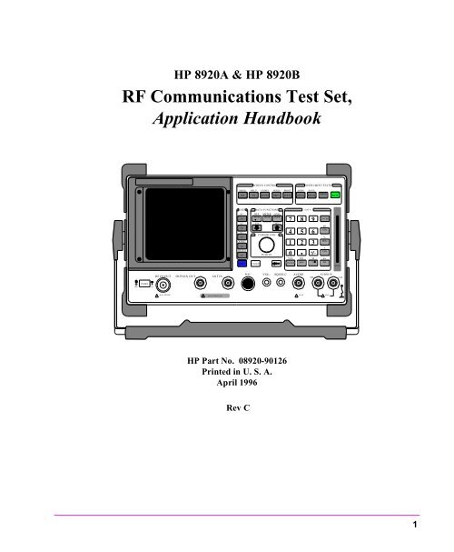
HP 8920A & HP 8920B<br />
<strong>RF</strong> <strong>Communications</strong> <strong>Test</strong> <strong>Set</strong>,<br />
<strong>Application</strong> <strong>Handbook</strong><br />
POWE<br />
OF O<br />
<strong>RF</strong> IN/OUT<br />
! MAX POWER<br />
DUPLEX OUT<br />
ANT IN<br />
! MAX POWER 200<br />
SCREEN CONTROL<br />
INSTRUMENT STATE<br />
MSSG HELP CONFI HOLD PRINT ADRS SAVE<br />
MEAS<br />
RX TX DUPLE PREV TESTS LOCAL RECAL<br />
PRESE<br />
USER DATA FUNCTIONS<br />
DATA<br />
SHIFT<br />
HP Part No. 08920-90126<br />
Printed in U. S. A.<br />
April 1996<br />
k1’<br />
k1<br />
k2’<br />
k2<br />
k3’<br />
k3<br />
ASSIG<br />
k4<br />
RELEA<br />
k5<br />
MIC/<br />
Rev C<br />
REF<br />
IN CR<br />
METER AVG<br />
INCR INCR<br />
LO HI<br />
CANCE<br />
CURSOR CON-<br />
PUSH TO<br />
VOL-<br />
SQUELC<br />
7 8 9<br />
4 5 6<br />
1 2 3<br />
0 + _<br />
YES<br />
ON/OFF<br />
NO<br />
ppm<br />
AUDIO<br />
! MAX<br />
Ω<br />
%<br />
HI<br />
ENTER<br />
dB<br />
GHz<br />
%<br />
MHz<br />
s<br />
kHz<br />
ms<br />
Hz<br />
AUDIO IN<br />
! MAX<br />
MEMO<br />
LO<br />
1
2<br />
Copyright © Hewlett-Packard Company 1994<br />
Notice Information contained in this document is subject to change without notice.<br />
All Rights Reserved. Reproduction, adaptation, or translation without<br />
prior written permission is prohibited, except as allowed under the copyright<br />
laws.<br />
This material may be reproduced by or for the U.S. Government pursuant<br />
to the Copyright License under the clause at DFARS 52.227-7013<br />
(APR 1988).<br />
Hewlett-Packard Company<br />
Learning Products Department<br />
24001 E. Mission<br />
Liberty Lake, WA 99019-9599<br />
U.S.A.
Manufacturer’s<br />
Declaration<br />
Herstellerbeschei<br />
nigung<br />
This statement is provided to comply with the requirements of<br />
the German Sound Emission Directive, from 18 January 1991.<br />
This product has a sound pressure emission (at the operator<br />
position) < 70 dB(A).<br />
• Sound Pressure Lp < 70 dB(A).<br />
• At Operator Position.<br />
• Normal Operation.<br />
• According to ISO 7779:1988/EN 27779:1991 (Type <strong>Test</strong>).<br />
Diese Information steht im Zusammenhang mit den Anforderungen der<br />
Maschinenlärminformationsverordnung vom 18 Januar 1991.<br />
• Schalldruckpegel Lp < 70 dB(A).<br />
• Am Arbeitsplatz.<br />
• Normaler Betrieb.<br />
• Nach ISO 7779:1988/EN 27779:1991 (Typprüfung).<br />
3
Safety<br />
Considerations<br />
4<br />
!<br />
GENERAL<br />
This product and related documentation must be reviewed for familiarization<br />
with safety markings and instructions before operation.<br />
This product is a Safety Class I instrument (provided with a protective<br />
earth terminal).<br />
SAFETY EARTH GROUND<br />
A unterruptible safety earth ground must be provided from the main<br />
power source to the product input wiring terminals, power cord, or supplied<br />
power cord set.<br />
CHASSIS GROUND TERMINAL<br />
To prevent a potential shock hazard, always connect the rear-panel chassis<br />
ground terminal to earth ground when operating this instrument from<br />
a dc power source.<br />
SAFETY SYMBOLS<br />
Indicates instrument damage can occur if indicated operating limits are<br />
exceeded.<br />
Indicates hazardous voltages.<br />
Indicates earth (ground) terminal<br />
WARNING A WARNING note denotes a hazard. It calls attention to a<br />
procedure, practice, or the like, which, if not correctly performed<br />
or adhered to, could result in personal injury. Do not proceed<br />
beyond a WARNING sign until the indicated conditions are fully<br />
understood and met.
CAUTION A CAUTION note denotes a hazard. It calls attentionto an operation<br />
procedure, practice, or the like, which, if not correctly performed or<br />
adhered to, could result in damage to or destruction of part or all of<br />
the product. Do not proceed beyond an CAUTION note until the<br />
indicated conditions are fully understood and met.<br />
Safety Considerations for this Instrument<br />
WARNING Any interruption of the protective (grounding) conductor (inside<br />
or outside the instrument) or disconnection of the protective<br />
earth terminal will cause a potential shock hazard that could<br />
result in personal injury. (Grounding one connector of a two<br />
conductor outlet is not sufficient protection.)<br />
Whenever it likely that the protection has been impaired, the<br />
instrument must be made inoperative and be secured against any<br />
unintended operation.<br />
If this instrument is to be energized via an auto transformer (for<br />
voltage reduction), make sure the common terminal is connected<br />
to the earth terminal of the power source.<br />
Servicing instructions are for use by service trained personnel<br />
only. To avoid dangerous electric shock, do not perform any<br />
servicing unless qualified to do so.<br />
Adjustments described in the manual are performed with power<br />
supplied to the instrument while protective covers are removed.<br />
Energy available at many points may, if contacted, result in<br />
personal injury.<br />
Capacitors inside the instrument may still be charged even if the<br />
instrument has been disconnected from its source of supply.<br />
For Continued protection against fire hazard, replace the line<br />
fuse(s) only with 250 V fuse(s) or the same current rating and<br />
type (for example, normal blow or time delay). Do not use<br />
repaired fuses or short circuited fuseholders.<br />
5
CERTIFICATION Hewlett-Packard Company certifies that this product met its published<br />
specifications at the time of shipment from the factory. Hewlett-Packard<br />
further certifies that its calibration measurements are traceable to the<br />
United States National Institute of Standards and Technology, to the extent<br />
allowed by the Institute’s calibration facility, and to the calibration<br />
facilities of other International Standards Organization members<br />
WARRANTY This Hewlett-Packard instrument product in warranted against defects<br />
in material and workmanship for a period of one year from date of shipment.<br />
During the warranty period, Hewlett-Packard Company will at its<br />
option, either repair or replace products which prove to be defective.<br />
6<br />
For warranty service or repair, this product must be returned to a service<br />
facility designated by HP. Buyer shall prepay shipping charges to HP<br />
and HP shall pay shipping charges, duties, and taxes for products returned<br />
to HP from another country.<br />
HP warrants that its software and Firmware designated by HP for use<br />
with an instrument will execute its programming instructions when<br />
properly installed on that instrument. HP does not warrant that the operation<br />
of the instrument, or software, or firmware will be uninterrupted<br />
or error free.
LIMITATION OF<br />
WARRANTY<br />
EXCLUSIVE<br />
REMEDIES<br />
The foregoing warranty shall not apply to defects resulting from improper<br />
or inadequate maintenance by Buyer, Buyer-supplied software or<br />
interfacing, unauthorized modification or misuse, operation outside of<br />
the environmental specifications for the product, or improper site preparation<br />
or maintenance.<br />
NO OTHER WARRANTY IS EXPRESSED OR IMPLIED. HP SPE-<br />
CIFICALLY DISCLAIMS THE IMPLIED WARRANTIES OF MER-<br />
CHANTABILITY AND FITNESS FOR A PARTIDCULAR<br />
PURPOSE.<br />
THE REMEDIES PROVIDED HEREIN ARE BUYER’S SOLE AND<br />
EXCLUSIVE REMEDIES. HP SHALL NOT BE LIABLE FOR ANY<br />
DIRECT, INDIRECT, SPECIAL, INCIDENTAL, OR CONSEQUEN-<br />
TIAL DAMAGES, WHETHER BASE ON CONTRACT, TORT, OR<br />
ANY OTHER LEGAL THEORY.<br />
ASSISTANCE Product maintenance agreements and other customer assistance agreements<br />
are available for Hewlett-Packard products. For any assistance,<br />
contact your nearest Hewlett-Packard Sales and Service Office.<br />
7
8<br />
DECLARATION OF CONFORMITY<br />
Manufacturer’s Name: Hewlett-Packard Company<br />
Manufacturer’s Address: Spokane Division<br />
24001 E. Mission Ave.<br />
Liberty Lake, WA 99019-9599<br />
Declares that the product(s):<br />
Product Name: <strong>RF</strong> <strong>Communications</strong> <strong>Test</strong> <strong>Set</strong><br />
Model Number(s): HP 8920A, 8920B<br />
Product Options: All<br />
Conforms to the following product specifications.<br />
Safety: HD 401/IEC 348<br />
EMC: EN 55011 (1991) /CISPR 11 (1990): ‘Group 1,<br />
Class A<br />
EMC: EN 50082-1 (1992)/IEC 801-2 (1991): 4 kV CD, 8<br />
kv AD<br />
Lines<br />
nal Lines<br />
Supplementary Information:<br />
/IEC 801-3 (1991): 3 V/m<br />
/IEC 801-4 (1991): 1k V Power<br />
0.5 kV Sig-<br />
The product herewith complies with the requirements of the Low Voltage<br />
Directive 73/23/EEC and EMC Directive 89/336/EEC.<br />
Spokane, Washington<br />
Date Vince Roland, SKD Quality Manager<br />
European Contact: Your local Hewlett-Packard Sales and Service Office or<br />
Hewlett-Packard GmbH. Dept. ZQ/Standards Europe, Herrenberger StarBe<br />
130, D-7030 Boblingen (Fax: +49-7031-14-3143).
In this Book This book is a guide for performing common radio tests using the <strong>Test</strong><br />
<strong>Set</strong>. This guide contains the following chapters and appendices.<br />
Chapter 1, Getting Started With The <strong>Test</strong> <strong>Set</strong><br />
This chapter contains a description of the manual contents, a general<br />
description of the <strong>Test</strong> <strong>Set</strong>, and a general description of the front and rear<br />
panel controls, indicators, and connectors.<br />
Chapter 2, Measurement Considerations<br />
This chapter contains a description of guidelines that must be adhere to<br />
when performing the measurements with the <strong>Test</strong> <strong>Set</strong>.<br />
Chapter 3, <strong>Test</strong>ing FM Radios<br />
This chapter contains the information required to use the <strong>Test</strong> <strong>Set</strong> to<br />
perform FM Transmitter and Receiver measurements.<br />
Chapter 4, <strong>Test</strong>ing AM Radios<br />
This chapter contains the information required to use the <strong>Test</strong> <strong>Set</strong> to<br />
perform AM Transmitter and Receiver measurements.<br />
Chapter 5, <strong>Test</strong>ing SSB Radios<br />
This chapter contains the information required to use the <strong>Test</strong> <strong>Set</strong> to<br />
perform SSB Transmitter and Receiver measurements.<br />
Chapter 6, Spectrum Analyzer Measurements<br />
This chapter contains the information about system measurements using the<br />
Spectrum Analyzer and Tracking Generator.<br />
Chapter 7, Spectrum Analyzer Measurements<br />
This chapter contains the information about system measurements using the<br />
Spectrum Analyzer and Tracking Generator.<br />
Chapter 7, Oscilloscope Measurements<br />
This chapter contains the information about system measurements using the<br />
Oscilloscope.<br />
9
10<br />
Chapter 8, Configuring For Measurements<br />
This chapter contains the information required to install the <strong>Test</strong> <strong>Set</strong> in<br />
preparation of performing measurements. Information provided includes<br />
instructions for power and printer connection, and initial power-up and<br />
configuration.<br />
Chapter 9, References<br />
This chapter lists any manuals, application notes, specifications, and<br />
standards referenced in this guide.<br />
Chapter 10, HP 8920A Specifications<br />
This chapter provides abbreviated specifications for the HP 8920A.<br />
Chapter 11, HP 8920B Specifications<br />
This chapter provides abbreviated specifications for the HP 8920B.<br />
Glossary<br />
This information lists the acronyms, abbreviations, and common terms used<br />
in this guide.
Contents<br />
1 Getting Started With The <strong>Test</strong> <strong>Set</strong><br />
Conventions Used In This Manual 24<br />
Product Description 25<br />
The <strong>Test</strong> <strong>Set</strong>’s Features 28<br />
11
Contents<br />
12<br />
2 Measurements Considerations<br />
Measurement Guideline 1 44<br />
Measurement Guideline 2 45<br />
Measurement Guideline 3 46<br />
Measurement Guideline 4 48
Contents<br />
3 <strong>Test</strong>ing FM Radios<br />
Introduction 50<br />
List of <strong>Test</strong>s 51<br />
FM Transmitters 52<br />
FM Receivers 79<br />
13
Contents<br />
14<br />
4 <strong>Test</strong>ing AM Radios<br />
Introduction 116<br />
List of <strong>Test</strong>s 117<br />
AM Transmitters 118<br />
AM Receivers 136
Contents<br />
5 <strong>Test</strong>ing SSB Radios<br />
Introduction 160<br />
List of <strong>Test</strong>s 161<br />
SSB Transmitters 162<br />
SSB Receivers 173<br />
15
Contents<br />
16<br />
6 Spectrum Analyzer Measurements<br />
Introduction 188<br />
List of Measurements 189<br />
Using the Spectrum Analyzer 190<br />
Using the Tracking Generator 205
Contents<br />
7 Oscilloscope Measurements<br />
Introduction 234<br />
Using the Oscilloscope 235<br />
17
Contents<br />
18<br />
8 Configuring for Measurements<br />
Preparing the <strong>Test</strong> <strong>Set</strong> for DC Operation 244
Contents<br />
9 References<br />
Manuals 250<br />
<strong>Application</strong> Note 251<br />
Specifications and Standards 252<br />
19
Contents<br />
20<br />
10 HP 8920A Specifications<br />
Signal Generator Specifications 255<br />
Audio Source Specifications 261<br />
<strong>RF</strong> Analyzer Specifications 262<br />
AF Analyzer Specifications 268<br />
Oscilloscope Specifications 271<br />
Spectrum Analyzer Specifications (Option 102) 272<br />
Signaling (Option 004) 276<br />
DC Current Meter (Option 103) 277<br />
Remote Programming (Option 103) 278<br />
Reference Oscillator Specifications 279<br />
Save/Recall Registers 280<br />
General Specifications 281
Contents<br />
11 HP 8920B Specifications<br />
Signal Generator Specifications 285<br />
Audio Source Specifications 291<br />
<strong>RF</strong> Analyzer Specifications 292<br />
AF Analyzer Specifications 297<br />
Oscilloscope Specifications 300<br />
Spectrum Analyzer Specifications (Option 102) 301<br />
Signaling (Option 004) 304<br />
DC Current Meter 305<br />
Remote Programming 306<br />
Memory Card Specifications 307<br />
Reference Oscillator Specifications 308<br />
General Specifications 309<br />
21
Contents<br />
22
1<br />
Getting Started With The <strong>Test</strong> <strong>Set</strong><br />
This chapter provides the user with a general introduction to the<br />
instrument. Information provided includes a general description of the<br />
<strong>Test</strong> <strong>Set</strong>, and a general description of the front and rear panel features.<br />
23
Conventions Used In This Manual<br />
Conventions Used In This Manual<br />
24<br />
The <strong>Test</strong> <strong>Set</strong> keys, screen titles, fields, and shifted functions are shown<br />
using the following conventions: (Refer to the RX TEST screen and<br />
the instrument front panel.)<br />
• Screen titles are shown in bold upper-case type −RX TEST<br />
• Field names and some measurements (such as AC Level) are indicated in<br />
lowercase bold type −<strong>RF</strong> Gen Freq<br />
• The contents of a field, and some measurements (such as SINAD) are<br />
shown in italics – −100.000000 or underlined – <strong>RF</strong> In<br />
• Key caps are shown in all capital letters − PRESET<br />
• The SHIFT key is pressed and released to access the blue-labeled functions<br />
printed above the keys. When a SHIFTed function is called-out in this manual,<br />
the use of the SHIFT key is assumed and is not usually indicated. The<br />
function to be accessed is shown in boxed italics text upper-case letters:<br />
MSSG.
Product Description<br />
Product Description<br />
The <strong>Test</strong> <strong>Set</strong> is a single instrument that combines the features of 22<br />
individual radio test instruments. The <strong>Test</strong> <strong>Set</strong> is designed to meet the<br />
communication test needs of both service and manufacturing<br />
environments, and the capability to test land mobile radios, cellular<br />
phones, and various other communications systems.<br />
<strong>Test</strong> and troubleshooting time is decreased by simplifying standard<br />
measurement tasks and providing the required measurement capability<br />
in a single instrument. Transmitters and receivers are characterized<br />
with single-key RX, TX and duplex tests. Each of these tests displays a<br />
specialized screen that provides access to the necessary controls and<br />
measurement results. Measured results may be displayed as digital<br />
readouts and/or bar graphs. All settings and measurements are easily<br />
accessed and changed using the front-panel knob and keys. If desired,<br />
all settings can be saved in nonvolatile save/recall registers for future<br />
access.<br />
The various ports on the <strong>Test</strong> <strong>Set</strong> allow the receiver/transmitter being<br />
tested to be quickly connected. A receiver with 2 μV sensitivity<br />
(typically
Product Description<br />
Features<br />
26<br />
The features currently available for the <strong>Test</strong> <strong>Set</strong> include:<br />
• Synthesized AM/FM signal generator to 1000 MHz<br />
• Function generator (HP 8920A option)<br />
• AM/FM modulation analyzer<br />
• Duplex offset generator<br />
• Signalling encoder and decoder (HP 8920A option)<br />
• SSB demodulator<br />
• <strong>RF</strong> power meter<br />
• <strong>RF</strong> frequency counter/frequency error meter<br />
• Audio frequency counter<br />
• AF power meter<br />
• AC/DC voltmeter<br />
• DC current meter (HP 8920A option)<br />
• SINAD meter<br />
• Distortion meter<br />
• Two variable audio sources<br />
• Digital oscilloscope<br />
• Spectrum analyzer and tracking generator (optional)<br />
• 2 μV sensitivity (typically
Specifications<br />
Product Description<br />
Abbreviated specifications for the <strong>Test</strong> <strong>Set</strong> are provided in "HP 8920A<br />
Specifications" on page 253 and "HP 8920B Specifications" on page 283.<br />
See the HP 8920A /B <strong>RF</strong> <strong>Communications</strong> <strong>Test</strong> <strong>Set</strong> Assembly Level<br />
Repair Guide for a complete list of specifications.<br />
27
The <strong>Test</strong> <strong>Set</strong>’s Features<br />
The <strong>Test</strong> <strong>Set</strong>’s Features<br />
Feature Contents<br />
28<br />
This section contains a brief description of the <strong>Test</strong> <strong>Set</strong>’s keys,<br />
connectors, controls, and screens. Additional operating information for<br />
all keys, connectors, controls, and screens can be found in the <strong>Test</strong><br />
<strong>Set</strong>’s user guide.<br />
"The <strong>Test</strong>’s <strong>Set</strong>s Front-Panel Features" on page 29.<br />
• "Screens" on page 29.<br />
• "Data Function Keys" on page 33.<br />
• "Knobs" on page 34.<br />
• "Screen Control Keys" on page 35.<br />
• "Instrument State Keys" on page 36.<br />
• "Data Keys" on page 37.<br />
• "Connectors" on page 38.<br />
• "Non-Bracketed Keys and Memory Card Slot" on page 39.<br />
"The <strong>Test</strong> <strong>Set</strong>’s Rear-Panel Features" on page 40<br />
• "Connectors" on page 40.<br />
• "Key and Fuse Holders" on page 41.
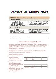
The <strong>Test</strong>’s <strong>Set</strong>s Front-Panel Features<br />
POWER<br />
OFF ON<br />
<strong>RF</strong> IN/OUT<br />
! MAX POWER 60 W<br />
CONTINUOUS<br />
Screens<br />
DUPLEX OUT<br />
!<br />
ANT IN<br />
MAX POWER 200 mW<br />
SCREEN CONTROL<br />
MSSG HELP CONFIG HOLD PRINT<br />
RX TX DUPLEX PREV TESTS<br />
The <strong>Test</strong> <strong>Set</strong>’s Features<br />
The CRT displays the various test screens, measurement results,<br />
waveforms, and messages. The a brief description is provided in the<br />
following:<br />
• “Screens that are Standard to the <strong>Test</strong> <strong>Set</strong>” on page 30.<br />
• “Screens that Require an Option” on page 31.<br />
• “Screens that Require an Optional Instrument” on page 31.<br />
ADRS<br />
LOCAL<br />
INSTRUMENT STATE<br />
SAVE<br />
RECALL<br />
USER DATA FUNCTIONS<br />
DATA<br />
k1’<br />
k1<br />
k2’<br />
k2<br />
k3’<br />
k3<br />
ASSIGN<br />
k4<br />
RELEASE<br />
k5<br />
SHIFT<br />
MIC/ACC<br />
REF SET METER AVG<br />
INCR<br />
: 10<br />
IN CR<br />
SET<br />
IN CR X10<br />
LO LIMIT HI LIMIT<br />
CANCEL<br />
CURSOR CONTROL<br />
PUSH TO SELECT<br />
VOLUME SQUELCH<br />
7 8 9<br />
4 5 6<br />
1 2 3<br />
0<br />
YES<br />
ON/OFF<br />
NO<br />
ppm<br />
W<br />
AUDIO OUT<br />
!<br />
MAX<br />
12 v Pk<br />
+ _<br />
Ω<br />
%<br />
dBμV<br />
HI<br />
MEAS<br />
RESET<br />
ENTER<br />
dB<br />
GHz<br />
dBm<br />
%<br />
MHz<br />
V<br />
s<br />
kHz<br />
mV<br />
ms<br />
Hz<br />
μV<br />
AUDIO IN<br />
! MAX<br />
42 v Pk<br />
PRESET<br />
MEMORY<br />
CARD<br />
LO<br />
29
The <strong>Test</strong> <strong>Set</strong>’s Features<br />
30<br />
Screens that are Standard to the <strong>Test</strong> <strong>Set</strong><br />
• RX <strong>Test</strong> − receiver test screen with <strong>RF</strong> and audio output controls and<br />
receiver measurement results.<br />
• TX <strong>Test</strong> − transmitter test screen with <strong>RF</strong> and audio input/output controls<br />
and transmitter measurement results.<br />
• Duplex <strong>Test</strong> − transmitter and receiver simultaneous test screen with <strong>RF</strong><br />
and audio input/output controls and transmitter and receiver measurement<br />
results.<br />
• <strong>Test</strong>s − access to creation, editing, copying, and execution of automated test<br />
programs loaded from Memory Cards, internal ROM/RAM, or an external<br />
disk drive.<br />
• <strong>RF</strong> Generator − used to control and display the <strong>RF</strong> and modulation signals.<br />
• <strong>RF</strong> Analyzer − used to process and display <strong>RF</strong> signal measurements.<br />
• AF Analyzer − used to process and display audio signal measurements.<br />
• Oscilloscope − used to display the oscilloscope measurement function, with<br />
vertical, time, trigger, and marker controls.<br />
• Configure − used to control the various functions including date, screen<br />
intensity, various <strong>RF</strong> controls, etc.<br />
• I/OConfigure − used to control the various functions including HP-IB,<br />
serial parameter, etc.<br />
• Print Configure − used to setup a printer.<br />
• Adjacent Channel Power − used to control measuring power of signals at a<br />
specific channel spacing above and below the <strong>RF</strong> Analyzer’s center<br />
frequency.
Screens that Require an Option<br />
The <strong>Test</strong> <strong>Set</strong>’s Features<br />
• Spectrum Analyzer − used to display the spectrum analyzer measurement<br />
function, with center frequency, span, reference level, marker, and tracking<br />
generator controls.<br />
• Encoder − used to display the signalling encoder function, with function<br />
generator, tone sequence, DTMF, CDCSS, digital paging, cellular and LTR<br />
and EDACS trunking subscreens.<br />
• Decoder − used to display the decoded data signalling with function<br />
generator, tone sequence, DTMF, CDCSS, digital paging, cellular and LTR<br />
and EDACS trunking subscreens.<br />
• Radio Interface − used to control the various functions of the optional radio<br />
interface.<br />
• Call Control − used to test AMPS TACS Cellular radios.<br />
Screens that Require an Optional Instrument<br />
• TDMA <strong>Test</strong><br />
• PDC <strong>Test</strong><br />
• PHP <strong>Test</strong><br />
• CDMA <strong>Test</strong><br />
• CDMA Analyzer<br />
• CDMA Generator<br />
• Code Domain<br />
• Call Control<br />
31
The <strong>Test</strong> <strong>Set</strong>’s Features<br />
32<br />
User Keys<br />
USER<br />
K1<br />
k1<br />
K2<br />
k2<br />
K3<br />
k3<br />
ASSIGN<br />
k4<br />
RELEASE<br />
k5<br />
SHIFT<br />
DATA FUNCTIONS<br />
REF SET<br />
INCR<br />
: 10<br />
User k1 - k5 keys − referred to as local keys, these keys enable you to<br />
instantly enable a field for fast or repetitive access. Local keys function<br />
for fields on the screen being displayed only.<br />
User k1’ - k3’ keys − referred to as global keys, these keys enable you<br />
to display and control a field from another screen while viewing<br />
another screen.<br />
To Assign a User Key<br />
1. Select the screen which the desired field is on.<br />
2. Position the cursor at the desired field using the Knob.<br />
3. Press the ASSIGN key.<br />
4. Press the desired k1-k5 or k1’-k3’ key.<br />
To Un-assign a User Key<br />
1. Select the screen which the desired field is on.<br />
2. Position the cursor at the desired field using the Knob.<br />
3. Press and release the SHIFT key.<br />
4. Press the RELEASE key.<br />
5. Press the ENTER key.<br />
METER<br />
INCR<br />
SET<br />
AVG<br />
INCR<br />
X10<br />
LO LIMIT HI LIMIT<br />
CANCEL<br />
CURSOR CONTROL<br />
PUSH TO SELECT<br />
7<br />
4<br />
1<br />
0<br />
YES<br />
ON/OFF
Data Function Keys<br />
USER<br />
K1<br />
k1<br />
K2<br />
k2<br />
K3<br />
k3<br />
ASSIGN<br />
k4<br />
RELEASE<br />
k5<br />
SHIFT<br />
DATA FUNCTIONS<br />
REF SET<br />
INCR<br />
: 10<br />
METER<br />
INCR<br />
SET<br />
The <strong>Test</strong> <strong>Set</strong>’s Features<br />
• The INCR ÷ 10, INCR SET, and INCR X10 keys change the increment/<br />
decrement field value (units, tens, hundreds, etc).<br />
• The keys increment/decrement field values, select among<br />
various field choices, or move the cursor within fields.<br />
• The LO LIMIT and HI LIMIT keys set measurement limits for PASS/FAIL<br />
indications.<br />
• The REF SET key sets or removes a measurement reference for relative<br />
AF and <strong>RF</strong> measurements.<br />
• The METER key enables/disables the analog bar-graph meter.<br />
• The AVG key enables/disables measurement averaging.<br />
AVG<br />
INCR<br />
X10<br />
LO LIMIT HI LIMIT<br />
CURSOR CONTROL<br />
CANCEL<br />
PUSH TO SELECT<br />
7<br />
4<br />
1<br />
0<br />
YES<br />
ON/OFF<br />
33
The <strong>Test</strong> <strong>Set</strong>’s Features<br />
34<br />
Knobs<br />
OUT<br />
ANT IN<br />
USER<br />
K1<br />
k1<br />
K2<br />
k2<br />
K3<br />
k3<br />
ASSIGN<br />
k4<br />
RELEASE<br />
k5<br />
SHIFT<br />
MIC/ACC<br />
DATA FUNCTIONS<br />
REF SET<br />
INCR<br />
: 10<br />
The Cursor Control Knob<br />
• Moves the cursor to another field (rotate CW/CCW).<br />
• Selects fields, screens, and settings from a list of choices. (push).<br />
• Increments and decrements numeric field values (push to select, rotate the<br />
knob to increment or decrement the value, then push again to enter).<br />
Volume and Squelch Knobs<br />
VOLUME Control − adjusts the speaker volume for monitoring.<br />
SQUELCH Control − adjusts the squelch threshold for AM, FM, or<br />
SSB signals.<br />
METER<br />
INCR<br />
SET<br />
AVG<br />
INCR<br />
X10<br />
LO LIMIT HI LIMIT<br />
CANCEL<br />
CURSOR CONTROL<br />
PUSH TO SELECT<br />
VOLUME<br />
SQUELCH<br />
7<br />
4<br />
1<br />
0<br />
YES<br />
ON/OFF<br />
AU
Screen Control Keys<br />
SCREEN CONTROL<br />
MSSG HELP CONFIG HOLD PRINT<br />
RX TX DUPLEX PREV TESTS<br />
These keys are used to access several instrument control and<br />
information screens.<br />
The <strong>Test</strong> <strong>Set</strong>’s Features<br />
• RX key − displays the RX TEST screen for test of receivers.<br />
• TX key − displays the TX TEST screen for test of transmitters.<br />
• DUPLEX key − displays the DUPLEX TEST screen for simultaneous test<br />
of transmitters/receivers.<br />
• PREV key − returns the display to the previous screen.<br />
• TESTS key − displays the TESTS (MAIN) screen used to access automated<br />
test program functions.<br />
• MSSG key − displays any error or operation messages since power-up.<br />
• HELP key − displays the HELP screen that provides operating assistance.<br />
• CONFIG key − displays the CONFIGURE screen defining general<br />
operating functions.<br />
• HOLD key − stops all measurements. Selecting again resumes<br />
measurement.<br />
• PRINT key − prints the entire contents of the displayed screen, the time and<br />
date, and any previously defined print title (if a printer is connected).<br />
ADRS<br />
LOCAL<br />
RECALL<br />
USER DATA FUNCTIONS<br />
DATA<br />
INSTRUMENT STATE<br />
SAVE<br />
MEAS<br />
RESET<br />
P<br />
35
The <strong>Test</strong> <strong>Set</strong>’s Features<br />
36<br />
Instrument State Keys<br />
SCREEN CONTROL<br />
MSSG HELP CONFIG HOLD PRINT<br />
RX TX DUPLEX PREV TESTS<br />
ADRS<br />
LOCAL<br />
RECALL<br />
USER DATA FUNCTIONS<br />
DATA<br />
INSTRUMENT STATE<br />
• LOCAL key − returns the instrument to manual control after HP- IB control<br />
is used.<br />
• RECALL key − lists and selects a previously stored instrument setup.<br />
• MEAS RESET key − clears the measurement “history” for all of the<br />
instrument’s measurement algorithms, and re-starts all measurements that<br />
were in progress.<br />
• PRESET key − restores most instrument settings to their factory default<br />
states. (Configure settings are not affected.)<br />
• ADRS key − displays the current HP-IB address.<br />
• SAVE key − stores an instrument setup.<br />
SAVE<br />
MEAS<br />
RESET<br />
PRESET
Data Keys<br />
USER DATA FUNCTIONS<br />
DATA<br />
K1<br />
k1<br />
K2<br />
k2<br />
K3<br />
k3<br />
ASSIGN<br />
k4<br />
RELEASE<br />
k5<br />
SHIFT<br />
REF SET<br />
INCR<br />
: 10<br />
METER<br />
INCR<br />
SET<br />
AVG<br />
INCR<br />
X10<br />
LO LIMIT HI LIMIT<br />
CURSOR CONTROL<br />
CANCEL<br />
PUSH TO SELECT<br />
7 8 9<br />
4 5 6<br />
1 2 3<br />
0<br />
YES<br />
ON/OFF<br />
NO<br />
ppm<br />
W<br />
The <strong>Test</strong> <strong>Set</strong>’s Features<br />
Data Entry keys− used to enter or change alphanumeric data (0-9, A-F,<br />
“.”, “+”, or “−”) for measurements or field entries. The EEX key is used<br />
to enter the exponent for scientific notation.<br />
Termination keys− used to input the entered data in the units selected.<br />
Also allows entry of “YES” or “NO” to confirm selected operations<br />
before they are executed.<br />
• ENTER key − selects a field or screen, and enters numbers when the unitof-measure<br />
is not changed or not specified.<br />
• ON/OFF key − enables and disables measurements, and turns numeric<br />
fields (such as Amplitude) on and off.<br />
+ _<br />
Ω<br />
%<br />
dBμV<br />
ENTER<br />
dB<br />
GHz<br />
dBm<br />
%<br />
MHz<br />
V<br />
s<br />
kHz<br />
mV<br />
ms<br />
Hz<br />
μV<br />
MEMORY<br />
CARD<br />
37
The <strong>Test</strong> <strong>Set</strong>’s Features<br />
POWER<br />
OFF ON<br />
38<br />
! MAX POWER 60 W<br />
<strong>RF</strong> IN/OUT<br />
CONTINUOUS<br />
Connectors<br />
DUPLEX OUT<br />
!<br />
ANT IN<br />
MAX POWER 200 mW<br />
SHIFT<br />
MIC/ACC<br />
CANCEL<br />
VOLUME<br />
SQUELCH<br />
<strong>RF</strong> IN/OUT Connector − type-N female connector for output signals<br />
from the <strong>RF</strong> Generator, and input signals (60 Watts continuous, or 100<br />
Watts for 10 sec/min) to the <strong>RF</strong> Analyzer. Nominal impedance is 50Ω..<br />
DUPLEX OUT Connector − female BNC connector for output <strong>RF</strong><br />
Generator and Tracking Generator signals. Nominal impedance is 50Ω.<br />
ANT IN Connector − female BNC connector for input and analysis of<br />
low-power <strong>RF</strong> signals (≤200 m Watts), and for off-the-air<br />
measurements. Nominal impedance is 50Ω.<br />
MIC/ACC Connector − 8-pin female DIN connector provides various<br />
connections including:<br />
• Audio microphone input for modulation of the <strong>RF</strong> output signal<br />
• Control of the <strong>RF</strong> Generator’s output state<br />
• Switching between the TX TEST and RX TEST screens<br />
• Provides keying signal to control a transmitter under test<br />
AUDIO OUT Connector − female BNC connector to output signals<br />
from AF Generators 1 and 2 (including encoder functions). Nominal<br />
output impedance is%
POWER<br />
FF ON<br />
<strong>RF</strong> IN/OUT<br />
Non-Bracketed Keys and Memory Card Slot<br />
DUPLEX OUT<br />
ANT IN<br />
Non-Bracketed Keys<br />
The POWER key − turns the instrument on or off.<br />
The <strong>Test</strong> <strong>Set</strong>’s Features<br />
The SHIFT key is used to select the blue-labeled functions listed above<br />
certain keys.<br />
The CANCEL key is used to cancel an entry in progress, or stop a<br />
running IBASIC program.<br />
The key is used to move the cursor to the left when entering<br />
numbers in a field, thereby erasing the previous characters.<br />
The Memory Card Slot<br />
K3<br />
k3<br />
ASSIGN<br />
k4<br />
RELEASE<br />
k5<br />
SHIFT<br />
MIC/ACC<br />
CURSOR CONTROL<br />
CANCEL<br />
PUSH TO SELECT<br />
VOLUME<br />
SQUELCH<br />
4 5 6<br />
1 2 3<br />
Slot for memory cards that are inserted to load software, or to record<br />
test results.<br />
0<br />
YES<br />
ON/OFF<br />
NO<br />
ppm<br />
W<br />
AUDIO OUT<br />
+ _<br />
Ω<br />
%<br />
dBμV<br />
HI<br />
dBm<br />
%<br />
MHz<br />
V<br />
s<br />
kHz<br />
mV<br />
ms<br />
Hz<br />
μV<br />
AUDIO IN<br />
MEMORY<br />
CARD<br />
LO<br />
39
The <strong>Test</strong> <strong>Set</strong>’s Features<br />
The <strong>Test</strong> <strong>Set</strong>’s Rear-Panel Features<br />
40<br />
DC CURRENT<br />
MEASUREMENT<br />
HP-IB<br />
(OPTIION)<br />
SERIAL PORT<br />
(OPTION)<br />
PARALLEL PORT<br />
(OPTIION)<br />
MODULATION<br />
INPUT<br />
CRT VIDEO<br />
OUTPUT<br />
EXT SCOPE<br />
TRIGGER<br />
10 MHz REF<br />
OUTPUT<br />
10 MHz REF<br />
INPUT<br />
AUDIO<br />
MONITOR<br />
DC INPUT<br />
15A 11-32 VDC<br />
Connectors<br />
• HP-IB Connector (optional) − 24-pin connector provides communication<br />
between the <strong>Test</strong> <strong>Set</strong> and other instruments or a computer using the IEEE<br />
488 Hewlett-Packard Interface Bus (HP-IB).<br />
• SERIAL PORT Connector (optional) − 6-pin RJ-11 dual serial (RS-232C)<br />
port for entering programs, printing test results and screen images, and<br />
sending test results to external devices.<br />
• DC CURRENT MEASUREMENT Terminals (optional) − dual banana<br />
jacks to measure from 0 to +10 ADC.<br />
• MODULATION INPUT Connector − female BNC connector to input an<br />
external signal to the modulators. Maximum input level is 12 V peak (full<br />
scale input = 1 V peak), and nominal input impedance is 600Ω.<br />
• CRT VIDEO OUTPUT Connector − female BNC connector provides CRT<br />
video to an external “multisync” video monitor.<br />
OPTION INTE<strong>RF</strong>ACE<br />
114.3<br />
MHz<br />
IF<br />
IQ<br />
<strong>RF</strong> IN<br />
DC<br />
FUSE<br />
CONTROL IO<br />
CW <strong>RF</strong><br />
IN<br />
HEADPHONE<br />
AC FUSE<br />
5A 250V<br />
AC DC
The <strong>Test</strong> <strong>Set</strong>’s Features<br />
• EXT SCOPE TRIGGER INPUT Connector − female BNC connector to<br />
input an external oscilloscope trigger. Maximum input level is ≈ 20 V peak.<br />
• 10 MHz REF OUTPUT Connector − female BNC connector outputs a 10<br />
MHz reference signal for locking external instruments.<br />
• 10 MHz REF INPUT Connector − female BNC connector to input an<br />
external 1, 2, 5, or 10 MHz reference signal.<br />
• AUDIO MONITOR OUTPUT Connector − female BNC connector<br />
provides an output from the AF Analyzer. Level is not affected by the<br />
VOLUME control, but is affected by the SQUELCH control.<br />
• Chassis Ground Terminal − provides a chassis connection. Also provides a<br />
safety ground when DC power is used.<br />
• RADIO INTE<strong>RF</strong>ACE Connector (optional) − 37 pin “D” style connector<br />
for parallel and serial communications, and audio/transmitter control lines<br />
between the <strong>Test</strong> <strong>Set</strong> and external radio equipment.<br />
• DC INPUT Connector − 2-pin female connector to input 11-28 Vdc @<br />
120W (maximum) for DC operation.<br />
• AC INPUT Connector − 3-pin male connector to input 100 to 240 Vac for<br />
AC operation.<br />
Key and Fuse Holders<br />
• AC/DC− selects the instrument’s power source.<br />
• DC FUSE Holder − 15A 250V fuse for DC operation.<br />
• AC FUSE Holder − 5A 250V fuse for AC operation.<br />
41
The <strong>Test</strong> <strong>Set</strong>’s Features<br />
42
2<br />
Measurements Considerations<br />
The following guidelines must be adhered to when performing any of<br />
the FM/AM/SSB Transmitter and Receiver, Spectrum Analyzer, or<br />
Oscilloscope Measurements.<br />
43
Measurement Guideline 1<br />
Measurement Guideline 1<br />
Connector Considerations<br />
CAUTION: The <strong>RF</strong> present at any <strong>Test</strong> <strong>Set</strong> input connector must not exceed the specified<br />
level or permanent instrument damage may result. If necessary, use an external<br />
attenuator. If overpower occurs, disconnect the Transmitter, then cycle <strong>Test</strong> <strong>Set</strong><br />
power OFF/ON to reset the protection circuitry.<br />
44<br />
<strong>RF</strong> IN/OUT<br />
The <strong>RF</strong> present at the <strong>Test</strong> <strong>Set</strong> <strong>RF</strong> IN/OUT connector must not exceed<br />
60W continuous (or 100 Watts for 10 sec/minute) or permanent<br />
instrument damage may result.<br />
ANT IN<br />
The <strong>RF</strong> present at the <strong>Test</strong> <strong>Set</strong> ANT IN connector must not exceed 200<br />
mW or permanent instrument damage may result.
Measurement Guideline 2<br />
Cabling and Adapter Considerations<br />
Measurement Guideline 2<br />
For most FM, AM, and SSB measurements, only the standard <strong>Test</strong> <strong>Set</strong><br />
with correct interconnecting cables and adapters are required.<br />
Output Power<br />
If output power is greater than 60W (continuous), an external<br />
attenuator is also required. Any other additional equipment or <strong>Test</strong> <strong>Set</strong><br />
options that are required to perform the measurement are listed in the<br />
procedure.<br />
Cabling <strong>Test</strong> Loads<br />
When measuring audio output, a <strong>Test</strong> Load with a resistance value<br />
dependent on the Receiver’s output impedance (normally 8 Ω) is<br />
required. In most cases, a non-inductive resistor with a power rating<br />
sufficient for the Receiver’s rated output power and resistance that<br />
matches the speaker impedance can be used. Typically, the test load is<br />
connected at the <strong>Test</strong> <strong>Set</strong> AUDIO IN connector using a BNC to dual<br />
banana adapter.<br />
Spectrum Analyzer<br />
For Spectrum Analyzer measurements, the Spectrum Analyzer/<br />
Tracking Generator option (002) must be installed in the <strong>Test</strong> <strong>Set</strong>.<br />
Oscilloscope<br />
For Oscilloscope Measurements, Hewlett-Packard’s HP 104XX series<br />
passive Oscilloscope probes can be used to input signals to the<br />
Oscilloscope via the front panel Audio Input or rear panel<br />
MODULATION INPUT connectors.<br />
45
Measurement Guideline 3<br />
Measurement Guideline 3<br />
Special <strong>Test</strong> Considerations<br />
46<br />
Information for performing any of the FM, AM, or SSB measurements:<br />
Coaxial Cable<br />
Use short runs of high quality coaxial cable and high quality adapters<br />
when connecting the device connected to the <strong>Test</strong> <strong>Set</strong> to ensure the<br />
most accurate power measurement. Double shielded coaxial cable is<br />
recommended when performing measurements on Cavities and<br />
Duplexers.<br />
Cable and Adapter Loss<br />
Remember that cable and adapter losses and mismatch must be<br />
considered when measuring <strong>RF</strong> power at VHF/UHF frequencies. If<br />
losses are known, they can be entered using the CONFIGURATION<br />
screen. Once entered, the measurement results are adjusted<br />
accordingly.<br />
Incidental Audio<br />
Incidental audio into a built-in or attached microphone may cause<br />
inaccurate readings. Whenever possible, disable the microphone input<br />
or minimize ambient audio during the measurement.<br />
Transmitter’s DTMF, CTCSS, and or CDCSS Functions<br />
Verify that the Transmitter’s DTMF, CTCSS, and/or CDCSS functions<br />
are OFF (if equipped), unless otherwise specified.<br />
Receiver <strong>Test</strong> Loads<br />
If using the <strong>Test</strong> Load, the measurement must be performed with only<br />
the load connected to the Receiver’s audio output circuitry (internal<br />
speaker disconnected). If the external speaker jack does not break the
Measurement Guideline 3<br />
internal speaker connection, either the <strong>Test</strong> <strong>Set</strong> AUDIO IN signal must<br />
be connected across the speaker (in this case, enter the impedance<br />
value of the speaker in lieu of the test load resistance), or the internal<br />
speaker must be physically disconnected.<br />
Measuring Audio Output Power<br />
When measuring audio output power in watts, always set Ext Load R<br />
field to the Receiver’s audio output impedance or to the test load<br />
resistance (when connected). Failure to do so will cause the<br />
measurement to be incorrect.<br />
Coded Squelch<br />
Certain receivers use CTCSS, CDCSS, or trunked radio signalling<br />
coded squelch. If the receiver is equipped with a coded squelch device<br />
that cannot be easily overridden, then the instruments AFGen2 or<br />
Encoder must be used to open the squelch for measurement. Also, if<br />
any of these are used, set Filter1 to 300Hz HPF to remove the tone used<br />
to open the squelch prior to measurement. Refer to the “RX” or<br />
“Encoder” screen sections in the <strong>Test</strong> <strong>Set</strong> User’s Guide supplied with<br />
the instrument for more information.<br />
47
Measurement Guideline 4<br />
Measurement Guideline 4<br />
Additional Measurement Considerations<br />
48<br />
Pressing the PRESET and TX or RX keys at the beginning of each test<br />
automatically configures the <strong>Test</strong> <strong>Set</strong> for “standard” transmitter/<br />
receiver measurements. The controls and settings that need to be<br />
adjusted during performance of the measurement are discussed in each<br />
procedure. Additional parameters or controls that may need to be<br />
adjusted when testing a particular radio are described in the “TX”,<br />
“RX”, “Spectrum Analyzer”, “Encoder”, and “Decoder” screen<br />
sections of the <strong>Test</strong> <strong>Set</strong> User’s Guide supplied with the instrument.
3<br />
<strong>Test</strong>ing FM Radios<br />
49
Introduction<br />
Introduction<br />
50<br />
Each procedure may contain the following information:<br />
• A brief measurement overview and a reference to applicable TIA/EIA specifications<br />
for each test.<br />
• A list of the <strong>Test</strong> <strong>Set</strong> options and additional test equipment required to perform<br />
the procedure.<br />
• Any special test considerations that need to be considered for safety, measurement<br />
accuracy, etc.<br />
• Step by step procedures required to perform each measurement (with illustrations).<br />
Refer to "Configuring for Measurements" on page 243, or the <strong>Test</strong> <strong>Set</strong>’s<br />
User Guide on preparing the <strong>Test</strong> <strong>Set</strong> for operation.
List of <strong>Test</strong>s<br />
List of <strong>Test</strong>s<br />
FM Transmitter Measurements<br />
"FM Off The Air Monitoring/Determining Unknown Transmitter<br />
Carrier Frequency" on page 53.<br />
"FM Output Power, Deviation, and Frequency/Frequency Error<br />
Measurement" on page 56.<br />
"FM Deviation and Symmetry Measurement" on page 59.<br />
"FM Microphone Sensitivity and Modulation Limiting Measurement"<br />
on page 62.<br />
"FM CTCSS Encoder Frequency and Deviation Measurement" on<br />
page 65.<br />
"FM CDCSS Coding and Deviation Measurements" on page 67.<br />
"FM DTMF Encodes and Deviation Measurement" on page 70.<br />
"FM Audio Distortion Measurement" on page 74.<br />
"FM Harmonics and Spurious Output Measurement" on page 76.<br />
FM Receiver Measurements<br />
"FM Audio Output Power Measurement" on page 80.<br />
"FM SINAD, Receiver Center Frequency, and Modulation Acceptance<br />
Bandwidth Measurement" on page 83.<br />
"FM Variation Of Sensitivity With Signal Frequency Measurement"<br />
on page 87.<br />
"FM 20 dB Quieting Sensitivity Measurement" on page 91.<br />
"FM Critical and Maximum Squelch Sensitivity Measurement" on<br />
page 94.<br />
"FM CTCSS Sensitivity and Bandwidth Measurement" on page<br />
97.<br />
"FM CDCSS Sensitivity Measurement" on page 101.<br />
"FM Audio Frequency Response Measurement" on page 105.<br />
"FM Audio Distortion Measurement" on page 108.<br />
"FM Spurious Response Attenuation Measurement" on page 111.<br />
51
FM Transmitters<br />
FM Transmitters<br />
52<br />
The following measurements are provided for testing FM Transmitters.<br />
The procedures are arranged in the order that tests are typically performed.
FM Transmitters<br />
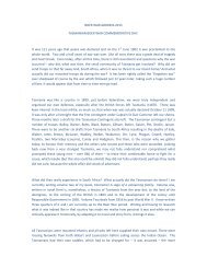
FM Off The Air Monitoring/Determining Unknown Transmitter Carrier Frequency<br />
Description<br />
This procedure is used to locate, demodulate, and measure an FM<br />
signal’s output carrier frequency. The low level signal is input to the<br />
front-panel ANT IN connector, located, then demodulated using the<br />
spectrum analyzer function.<br />
NOTE: For performing an FM Off the Air Monitoring on a Known Transmitter<br />
Carrier Frequency, see page 55.<br />
If attempting to determine the unknown frequency of a Transmitter connected<br />
to the <strong>RF</strong> IN/OUT connector, see “Output Power, Deviation, and Frequency<br />
or Frequency Error Measurement” provided later in this chapter for the<br />
measurement procedure.<br />
POWER<br />
OFF ON<br />
SPECTRUM ANALYZER<br />
<strong>RF</strong> IN/OUT<br />
! MAX POWER 60 W<br />
CONTINUOUS<br />
DUPLEX OUT<br />
!<br />
ANT IN<br />
MAX POWER 200 mW<br />
1<br />
SCREEN CONTROL<br />
MSSG HELP CONFIG HOLD PRINT<br />
RX TX DUPLEX PREV TESTS<br />
ADRS<br />
LOCAL<br />
INSTRUMENT STATE<br />
SAVE<br />
RECALL<br />
USER DATA FUNCTIONS<br />
DATA<br />
k1’<br />
k1<br />
k2’<br />
k2<br />
k3’<br />
k3<br />
ASSIGN<br />
k4<br />
RELEASE<br />
k5<br />
SHIFT<br />
MIC/ACC<br />
Knob<br />
REF SET METER AVG<br />
INCR<br />
: 10<br />
IN CR<br />
SET<br />
IN CR X10<br />
LO LIMIT HI LIMIT<br />
CANCEL<br />
CURSOR CONTROL<br />
PUSH TO SELECT<br />
VOLUME SQUELCH<br />
Data Entry<br />
Keys<br />
7 8 9<br />
4 5 6<br />
1 2 3<br />
0<br />
YES<br />
ON/OFF<br />
NO<br />
ppm<br />
W<br />
AUDIO OUT<br />
!<br />
MAX<br />
12 v Pk<br />
+ _<br />
Ω<br />
%<br />
dBμV<br />
HI<br />
MEAS<br />
RESET<br />
ENTER<br />
dB<br />
GHz<br />
dBm<br />
%<br />
MHz<br />
V<br />
s<br />
kHz<br />
mV<br />
ms<br />
Hz<br />
μV<br />
AUDIO IN<br />
! MAX<br />
42 v Pk<br />
PRESET<br />
MEMORY<br />
CARD<br />
LO<br />
2<br />
53
FM Transmitters<br />
54<br />
<strong>Test</strong> <strong>Set</strong> Options Required<br />
Additional Equipment<br />
Required<br />
Measurement Procedure:<br />
1 Connect the Antenna to the ANT IN connector.<br />
CAUTION: Do not exceed the connector’s rated input or permanent instrument damage<br />
may result.<br />
On the <strong>Test</strong> <strong>Set</strong>:<br />
Spectrum Analyzer/Tracking Generator (option 102)<br />
Whip antenna<br />
2 Press the PRESET key.<br />
❒ If monitoring an FM broadcast signal perform the following steps:<br />
a Press the TX key.<br />
b Use the knob to change IF Filter to 230 kHz.<br />
c Continued to step 3.<br />
❒ If not proceed to step 3.<br />
Using the knob and data entry keys:<br />
3 Select the SPEC ANL screen.<br />
4 From the Controls select Ant.<br />
5 <strong>Set</strong> Center Freq and Span fields to view desired spectrum.<br />
6 <strong>Set</strong> Ref Level from −30 dBm to −50 dBm as required to view the desired<br />
signal.
Once the desired carrier is found:<br />
7 From Controls, select Main.<br />
8 Select Marker from the Choices field.<br />
9 Use the Marker To field to select the desired carrier.<br />
On the <strong>Test</strong> <strong>Set</strong> frequency and level are displayed as shown.<br />
SPECTRUM ANALYZER<br />
BW= 3 kHz<br />
Marker<br />
Freq MHz<br />
101.12980<br />
Lvl dBm<br />
-99.92<br />
FM Transmitters<br />
Level & Frequency<br />
displayed<br />
10 To demodulate the carrier:<br />
a With the marker on the desired carrier, select Marker To to Center<br />
Freq.<br />
b From Controls, select Main.<br />
c Select Marker from the Choices field.<br />
d Decrease the Span to 1.5 MHz (or less).<br />
e Adjust the Volume and Squelch controls to listen to the demodulated<br />
carrier.<br />
FM Off The Air Monitoring on a Known Transmitter Carrier Frequency<br />
1 Press the PRESET key.<br />
2 Press the TX key.<br />
3 <strong>Set</strong> Tune Mode to Manual.<br />
4 <strong>Set</strong> Tune Freq to known frequency.<br />
5 <strong>Set</strong> Input Port to Ant<br />
6 <strong>Set</strong> IF Filter to 230 kHz (if necessary).<br />
55
FM Transmitters<br />
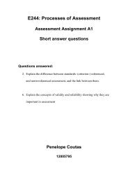
FM Output Power, Deviation, and Frequency/Frequency Error Measurement<br />
56<br />
POWER<br />
OFF ON<br />
50Ω COXIAL<br />
CABLE<br />
Description<br />
This procedure is used to measure an FM Transmitter’s output carrier<br />
power and frequency (or frequency error) into 50 Ω. For FM<br />
Transmitters, deviation and modulating frequency are also measured.<br />
FM reference is ANSI/EIA-RS-152-C-1988, RS-316-C.<br />
<strong>RF</strong> IN/OUT<br />
! MAX POWER 60 W<br />
CONTINUOUS<br />
TX TEST<br />
DUPLEX OUT<br />
1<br />
ANTENNA<br />
(<strong>RF</strong> OUT)<br />
!<br />
ANT IN<br />
MAX POWE R 20 0 mW<br />
3<br />
SCREEN CONTROL<br />
MSSG HELP CONFIG HOLD PRINT<br />
RX TX DUPLEX PREV TESTS<br />
ADRS<br />
LOCAL<br />
INSTRUMENT STATE<br />
SAVE<br />
RECALL<br />
USER DATA FUNCTIONS<br />
DATA<br />
k1’<br />
k1<br />
k2’<br />
k2<br />
k3’<br />
k3<br />
ASSIGN<br />
k4<br />
RELEASE<br />
k5<br />
SHIFT<br />
Knob<br />
MIC/ACC<br />
REF SET METER AVG<br />
INCR<br />
: 10<br />
IN CR<br />
SET<br />
IN CR X10<br />
LO LIMIT HI LIMIT<br />
CANCEL<br />
CURSOR CONTROL<br />
PUSH TO SELECT<br />
VOLUME SQUELCH<br />
ATTENUATOR (OPTIONAL)<br />
TRANSMITTER UNDER TEST<br />
Data Entry<br />
Keys<br />
7 8 9<br />
4 5 6<br />
1 2 3<br />
0<br />
YES<br />
ON/OFF<br />
!<br />
NO<br />
ppm<br />
W<br />
AUDIO OUT<br />
MAX<br />
12 v Pk<br />
+ _<br />
Ω<br />
%<br />
dBμV<br />
HI<br />
MEAS<br />
RESET<br />
ENTER<br />
dB<br />
GHz<br />
dBm<br />
%<br />
MHz<br />
V<br />
s<br />
kHz<br />
mV<br />
ms<br />
Hz<br />
μV<br />
AUDIO IN<br />
! MAX<br />
42 v Pk<br />
PRESET<br />
MEMORY<br />
CARD<br />
LO<br />
2<br />
SHEILDED<br />
AUDIO CABLE<br />
MICROPHONE<br />
(AUDIO INPUT)
<strong>Test</strong> <strong>Set</strong> Options Required<br />
Measurement Procedure:<br />
1 Connect the Transmitter Under <strong>Test</strong> as shown.<br />
FM Transmitters<br />
CAUTION: The <strong>RF</strong> present at the <strong>Test</strong> <strong>Set</strong> <strong>RF</strong> IN/OUT connector must not exceed 60W<br />
continuous (or 100 Watts for 10 sec/minute).<br />
On the <strong>Test</strong> <strong>Set</strong>:<br />
2 Press the PRESET key.<br />
3 Press the TX key.<br />
The typical error for the standard <strong>Test</strong> <strong>Set</strong> timebase is<br />
2-3 Hz per 1 MHz (when measuring carrier frequency). If greater<br />
accuracy is required, use a <strong>Test</strong> with Option 001 (High Stability<br />
Timebase).<br />
Special <strong>Test</strong> Considerations "Cable and Adapter Loss" on page 46.<br />
Using the knob and data entry keys:<br />
4 <strong>Set</strong> AFGen1 Lvl to the correct output level for the desired frequency deviation<br />
(refer to microphone sensitivity and deviation specifications for the<br />
Transmitter being tested).<br />
5 <strong>Set</strong> Filter 1 to 300 Hz HPF.<br />
6 <strong>Set</strong> Filter 2 to 3 kHz LPF.<br />
7 <strong>Set</strong> De-Emphasis to Off.<br />
NOTE: If the <strong>Test</strong> <strong>Set</strong> is equipped with the CCITT filter option, set Filter 1 to<br />
FM Transmitters<br />
58<br />
8. Determine if actual frequency readout or frequency error is the desired<br />
measurement.<br />
❒ For actual frequency readout, continue with step 9<br />
❒ For frequency error:<br />
• <strong>Set</strong> Tune Mode to Manual.<br />
• <strong>Set</strong> Tune Freq to the expected carrier frequency.<br />
On the Radio:<br />
9 Key the Transmitter.<br />
As long as the Transmitter is keyed the measurement results will display.<br />
Frequency<br />
Frequency<br />
Output<br />
Power<br />
TX TEST<br />
TX Freq Error MHz<br />
kHz<br />
TX Frequency<br />
TX Power<br />
Tune Mode<br />
Auto/Manual<br />
Tune Freq<br />
145.280000<br />
MHz<br />
TX Pwr Zero<br />
Zero<br />
0.169 3.579<br />
145.280024<br />
Input Port<br />
<strong>RF</strong> in/Ant<br />
IF Filter<br />
15 kHz<br />
Ext TX Key<br />
On/Off<br />
kHz<br />
W<br />
TX TEST<br />
FM Deviation<br />
AF Anl In<br />
FM Demod<br />
Filter 1<br />
300Hz HPF<br />
Filter 2<br />
3kHz LPF<br />
De-Emphasis<br />
750 us/Off<br />
Detector<br />
Pk+-Max<br />
AF Freq<br />
3.579<br />
2.03 1.00004<br />
AFGen1 Freq<br />
1.0000 MHz<br />
AFGen1 Lvl<br />
-45.5 dBm<br />
kHz<br />
kHz<br />
To Screen<br />
<strong>RF</strong> GEN<br />
<strong>RF</strong> ANL<br />
AF ANL<br />
SCOPE<br />
SPEC ANL<br />
ENCODER<br />
DECODER<br />
RADIO INT<br />
More<br />
Frequency <br />
Modulating<br />
Fre-
FM Deviation and Symmetry Measurement<br />
POWER<br />
OFF ON<br />
50Ω COXIAL<br />
CABLE<br />
FM Transmitters<br />
This procedure is used to measure an FM Transmitter’s frequency<br />
deviation and deviation symmetry. FM deviation is displayed on the<br />
<strong>Test</strong> <strong>Set</strong>. Deviation symmetry requires measuring the plus and minus<br />
peaks, then calculating symmetry.<br />
<strong>RF</strong> IN/OUT<br />
! MAX POWER 60 W<br />
CONTINUOUS<br />
TX TEST<br />
DUPLEX OUT<br />
1<br />
ANTENNA<br />
(<strong>RF</strong> OUT)<br />
!<br />
ANT IN<br />
MAX POWER 200 mW<br />
3<br />
SCREEN CONTROL<br />
MSSG HELP CONFIG HOLD PRINT<br />
RX TX DUPLEX PREV TESTS<br />
ADRS<br />
LOCAL<br />
INSTRUMENT STATE<br />
SAVE<br />
RECALL<br />
USER DATA FUNCTIONS<br />
DATA<br />
k1’<br />
k1<br />
k2’<br />
k2<br />
k3’<br />
k3<br />
ASSIGN<br />
k4<br />
RELEASE<br />
k5<br />
SHIFT<br />
Knob<br />
MIC/ACC<br />
REF SET METER AVG<br />
INCR<br />
: 10<br />
INCR<br />
SET<br />
INCR X10<br />
LO LIMIT HI LIMIT<br />
CANCEL<br />
CURSOR CONTROL<br />
PUSH TO SELECT<br />
VOLUME SQUELCH<br />
ATTENUATOR (OPTIONAL)<br />
TRANSMITTER UNDER TEST<br />
Data Entry<br />
Keys<br />
7 8 9<br />
4 5 6<br />
1 2 3<br />
0<br />
YES<br />
ON/OFF<br />
!<br />
NO<br />
ppm<br />
W<br />
AUDIO OUT<br />
MAX<br />
12 v Pk<br />
+ _<br />
Ω<br />
%<br />
dBμV<br />
HI<br />
MEAS<br />
RESET<br />
ENTER<br />
dB<br />
GHz<br />
dBm<br />
%<br />
MHz<br />
V<br />
s<br />
kHz<br />
mV<br />
ms<br />
Hz<br />
μV<br />
AUDIO IN<br />
! MAX<br />
42 v Pk<br />
PRESET<br />
ME MORY<br />
CARD<br />
LO<br />
2<br />
SHEILDED<br />
AUDIO CABLE<br />
MICROPHONE<br />
(AUDIO INPUT)<br />
59
FM Transmitters<br />
60<br />
Measurement Procedure:<br />
1 Connect the Transmitter Under <strong>Test</strong> as shown.<br />
CAUTION: The <strong>RF</strong> present at the <strong>Test</strong> <strong>Set</strong> <strong>RF</strong> IN/OUT connector must not exceed 60W<br />
continuous (or 100 Watts for 10 sec/minute).<br />
On the <strong>Test</strong> <strong>Set</strong>:<br />
2 Press the PRESET key.<br />
3 Press the TX key.<br />
On the Radio:<br />
4 Key the Transmitter and keep keyed until the remaining steps are complete.<br />
On the <strong>Test</strong> <strong>Set</strong> using the knob and data entry keys:<br />
5 <strong>Set</strong> AFGen1 Lvl so that displayed FM deviation is 60% of the Transmitter’s<br />
specified maximum frequency deviation (typically 3 kHz).<br />
On the <strong>Test</strong> <strong>Set</strong> measured FM Deviation is displayed as shown.<br />
TX Frequency<br />
TX Power<br />
Tune Mode<br />
Auto/Manual<br />
Tune Freq<br />
145.280000<br />
MHz<br />
TX Pwr Zero<br />
Zero<br />
144.680040<br />
IF Filter<br />
15 kHz<br />
To measure FM symmetry on the <strong>Test</strong> <strong>Set</strong>:<br />
6 <strong>Set</strong> Detector to Pk−.<br />
7 Record the displayed FM Deviation as Pk−.<br />
8 <strong>Set</strong> Detector to Pk+.<br />
Input Port<br />
<strong>RF</strong> in/Ant<br />
Ext TX Key<br />
On/Off<br />
kHz<br />
W<br />
TX TEST<br />
FM Deviation<br />
AF Anl In<br />
FM Demod<br />
Filter 1<br />
300Hz HPF<br />
Filter 2<br />
3kHz LPF<br />
De-Emphasis<br />
750 us/Off<br />
Detector<br />
Pk+-Max<br />
AF Freq<br />
Deviation<br />
2.971<br />
0.591 1.00007<br />
AFGen1 Freq<br />
1.0000 MHz<br />
AFGen1 Lvl<br />
-45.5 dBm<br />
kHz<br />
kHz<br />
To Screen<br />
<strong>RF</strong> GEN<br />
<strong>RF</strong> ANL<br />
AF ANL<br />
SCOPE<br />
SPEC ANL<br />
ENCODER<br />
DECODER<br />
RADIO INT<br />
More
9 Record the displayed FM Deviation as Pk+.<br />
Calculate the Measurement:<br />
10 Calculate the Deviation Symmetry as follows:<br />
Deviation Symmetry (in percent) =<br />
For example, =<br />
(3.010) - (2.971)<br />
(3.010<br />
(Pk +) - (Pk -)<br />
(Pk +)<br />
X 100 = 1.29<br />
X 100<br />
FM Transmitters<br />
61
FM Transmitters<br />
FM Microphone Sensitivity and Modulation Limiting Measurement<br />
62<br />
POWER<br />
OFF ON<br />
50Ω COXIAL<br />
CABLE<br />
Description<br />
This procedure is used to measure an FM Transmitter’s audio input<br />
sensitivity, and modulation limiting capability (if available).<br />
Modulation limiting is verified over the Transmitter’s audio frequency<br />
range. FM reference is ANSI/EIA-RS-152-C-1988 RS-316-B.<br />
<strong>RF</strong> IN/OUT<br />
! MAX POWER 60 W<br />
CONTINUOUS<br />
TX TEST<br />
DUPLEX OUT<br />
1<br />
ANTENNA<br />
(<strong>RF</strong> OUT)<br />
!<br />
ANT IN<br />
MAX POWE R 20 0 mW<br />
3<br />
SCREEN CONTROL<br />
MSSG HELP CONFIG HOLD PRINT<br />
RX TX DUPLEX PREV TESTS<br />
ADRS<br />
LOCAL<br />
INSTRUMENT STATE<br />
SAVE<br />
RECALL<br />
USER DATA FUNCTIONS<br />
DATA<br />
k1’<br />
k1<br />
k2’<br />
k2<br />
k3’<br />
k3<br />
ASSIGN<br />
k4<br />
RELEASE<br />
k5<br />
SHIFT<br />
Knob<br />
MIC/ACC<br />
REF SET METER AVG<br />
INCR<br />
: 10<br />
IN CR<br />
SET<br />
IN CR X10<br />
LO LIMIT HI LIMIT<br />
CANCEL<br />
CURSOR CONTROL<br />
PUSH TO SELECT<br />
VOLUME SQUELCH<br />
ATTENUATOR (OPTIONAL)<br />
TRANSMITTER UNDER TEST<br />
Data Entry<br />
Keys<br />
7 8 9<br />
4 5 6<br />
1 2 3<br />
0<br />
YES<br />
ON/OFF<br />
!<br />
NO<br />
ppm<br />
W<br />
AUDIO OUT<br />
MAX<br />
12 v Pk<br />
+ _<br />
Ω<br />
%<br />
dBμV<br />
HI<br />
MEAS<br />
RESET<br />
ENTER<br />
dB<br />
GHz<br />
dBm<br />
%<br />
MHz<br />
V<br />
s<br />
kHz<br />
mV<br />
ms<br />
Hz<br />
μV<br />
AUDIO IN<br />
! MAX<br />
42 v Pk<br />
PRESET<br />
MEMORY<br />
CARD<br />
LO<br />
2<br />
SHEILDED<br />
AUDIO CABLE<br />
MICROPHONE<br />
(AUDIO INPUT)
Special <strong>Test</strong> Considerations See "Incidental Audio" on page 46.<br />
Measurement Procedure:<br />
1 Connect the Transmitter as shown.<br />
FM Transmitters<br />
CAUTION: The <strong>RF</strong> present at the <strong>Test</strong> <strong>Set</strong> <strong>RF</strong> IN/OUT connector must not exceed 60W<br />
continuous (or 100 Watts for 10 sec/minute).<br />
On the <strong>Test</strong> <strong>Set</strong>:<br />
2 Press the PRESET key.<br />
3 Press the TX key.<br />
Using the knob and data keys:<br />
4 <strong>Set</strong> Filter 1 to 300 Hz HPF.<br />
5 <strong>Set</strong> Filter 2 to 3 kHz LPF.<br />
On the Radio:<br />
6 Key the Transmitter and keep keyed until the remaining steps are completed<br />
On the <strong>Test</strong> <strong>Set</strong> using the knob and data entry keys:<br />
7 <strong>Set</strong> AFGen1 Lvl so that displayed FM deviation is 60% of the Transmitter’s<br />
specified frequency deviation (typically 3 kHz).<br />
On the <strong>Test</strong> <strong>Set</strong> Microphone Sensitivity is shown as AFGen1 Lvl.<br />
63
FM Transmitters<br />
64<br />
TX Frequency<br />
TX Power<br />
Tune Mode<br />
Auto/Manual<br />
Tune Freq<br />
145.280000<br />
MHz<br />
TX Pwr Zero<br />
Zero<br />
145.280024<br />
Input Port<br />
<strong>RF</strong> in/Ant<br />
IF Filter<br />
15 kHz<br />
Ext TX Key<br />
On/Off<br />
8 <strong>Set</strong> AFGen1 Lvl measurement units to dBm.<br />
kHz<br />
9 Increase AFGen1 Lvl by 20 dB.<br />
W<br />
TX TEST<br />
FM Deviation<br />
AF Anl In<br />
FM Demod<br />
Filter 1<br />
300Hz HPF<br />
Filter 2<br />
3kHz LPF<br />
De-Emphasis<br />
750 us/Off<br />
Detector<br />
Pk+-Max<br />
AF Freq<br />
2.965<br />
2.03 1.00004<br />
AFGen1 Freq<br />
1.0000 MHz<br />
AFGen1 Lvl<br />
-45.5 dBm<br />
Microphone<br />
Sensitivity<br />
To Screen<br />
<strong>RF</strong> GEN<br />
<strong>RF</strong> ANL<br />
AF ANL<br />
SCOPE<br />
SPEC ANL<br />
ENCODER<br />
DECODER<br />
RADIO INT<br />
Displayed FM deviation should not exceed the Transmitter’s maximum<br />
specified deviation.<br />
10 Change AFGen1 Freq from 300 Hz to 3 kHz (in 100 Hz increments).<br />
11 Verify that the displayed FM deviation does not exceed the Transmitter’s<br />
maximum specified deviation.<br />
kHz<br />
kHz<br />
More
FM CTCSS Encoder Frequency and Deviation Measurement<br />
POWER<br />
OFF ON<br />
50Ω COXIAL<br />
CABLE<br />
Description<br />
FM Transmitters<br />
This procedure is used to measure an FM Transmitter’s Continuous<br />
Tone Coded Squelch System (CTCSS) encoder frequency and<br />
frequency deviation. Both frequency and deviation are read directly off<br />
the <strong>Test</strong> <strong>Set</strong> screen. FM reference is ANSI/EIA RS-220-A.<br />
<strong>RF</strong> IN/OUT<br />
! MAX POWER 60 W<br />
CONTINUOUS<br />
TX TEST<br />
DUPLEX OUT<br />
1<br />
ANTENNA<br />
(<strong>RF</strong> OUT)<br />
!<br />
ANT IN<br />
MAX POWER 200 mW<br />
3<br />
SCREEN CONTROL<br />
MSSG HELP CONFIG HOLD PRINT<br />
RX TX DUPLEX PREV TESTS<br />
ADRS<br />
LOCAL<br />
INSTRUMENT STATE<br />
SAVE<br />
RECALL<br />
USER DATA FUNCTIONS<br />
DATA<br />
k1’<br />
k1<br />
k2’<br />
k2<br />
k3’<br />
k3<br />
ASSIGN<br />
k4<br />
RELEASE<br />
k5<br />
SHIFT<br />
Knob<br />
MIC/ACC<br />
REF SET METER AVG<br />
INCR<br />
: 10<br />
INCR<br />
SET<br />
INCR X10<br />
LO LIMIT HI LIMIT<br />
CANCEL<br />
CURSOR CONTROL<br />
PUSH TO SELECT<br />
VOLUME SQUELCH<br />
ATTENUATOR (OPTIONAL)<br />
TRANSMITTER UNDER TEST<br />
Data Entry<br />
Keys<br />
7 8 9<br />
4 5 6<br />
1 2 3<br />
0<br />
YES<br />
ON/OFF<br />
!<br />
NO<br />
ppm<br />
W<br />
AUDIO OUT<br />
MAX<br />
12 v Pk<br />
+ _<br />
Ω<br />
%<br />
dBμV<br />
HI<br />
MEAS<br />
RESET<br />
ENTER<br />
dB<br />
GHz<br />
dBm<br />
%<br />
MHz<br />
V<br />
s<br />
kHz<br />
mV<br />
ms<br />
Hz<br />
μV<br />
AUDIO IN<br />
! MAX<br />
42 v Pk<br />
PRESET<br />
ME MORY<br />
CARD<br />
LO<br />
2<br />
SHEILDED<br />
AUDIO CABLE<br />
MICROPHONE<br />
(AUDIO INPUT)<br />
65
FM Transmitters<br />
66<br />
Measurement Procedure:<br />
1 Connect the Transmitter as shown.<br />
CAUTION: The <strong>RF</strong> present at the <strong>Test</strong> <strong>Set</strong> <strong>RF</strong> IN/OUT connector must not exceed 60W<br />
continuous (or 100 Watts for 10 sec/minute).<br />
On the <strong>Test</strong> <strong>Set</strong>:<br />
2 Press the PRESET key.<br />
3 Press the TX key.<br />
On the Radio:<br />
4 Key the Transmitter and keep keyed until the remaining steps are completed.<br />
On the <strong>Test</strong> <strong>Set</strong> using the knob and data entry keys:<br />
5 <strong>Set</strong> Filter 2 to 300 Hz LPF.<br />
On the <strong>Test</strong> <strong>Set</strong> Tone frequency deviation is displayed as FM Deviation as<br />
shown.<br />
On the <strong>Test</strong> <strong>Set</strong> Tone frequency is displayed as AF Freq.<br />
TX Frequency<br />
TX Power<br />
Tune Mode<br />
Auto/Manual<br />
Tune Freq<br />
145.280000<br />
MHz<br />
TX Pwr Zero<br />
Zero<br />
145.890058<br />
Input Port<br />
<strong>RF</strong> in/Ant<br />
IF Filter<br />
15 kHz<br />
Ext TX Key<br />
On/Off<br />
kHz<br />
W<br />
TX TEST<br />
FM Deviation<br />
AF Anl In<br />
FM Demod<br />
Filter 1<br />
300Hz HPF<br />
Filter 2<br />
3kHz LPF<br />
De-Emphasis<br />
750 us/Off<br />
Detector<br />
Pk+-Max<br />
AF Freq<br />
0.980<br />
0.587 0.10354<br />
AFGen1 Freq<br />
1.0000 MHz<br />
AFGen1 Lvl<br />
-45.5 dBm<br />
kHz<br />
kHz<br />
To Screen<br />
<strong>RF</strong> GEN<br />
<strong>RF</strong> ANL<br />
AF ANL<br />
SCOPE<br />
SPEC ANL<br />
ENCODER<br />
DECODER<br />
RADIO INT<br />
More<br />
Tone Deviation<br />
Tone Frequency
FM CDCSS Coding and Deviation Measurements<br />
POWER<br />
OFF ON<br />
50Ω COXIAL<br />
CABLE<br />
Description<br />
FM Transmitters<br />
This procedure is used to analyze an FM Transmitter’s Continuous<br />
Digital Coded Squelch System (CDCSS) digital data stream and<br />
frequency deviation. The data rate, binary data stream, and octal code<br />
are all displayed on the <strong>Test</strong> <strong>Set</strong> screen.<br />
<strong>RF</strong> IN/OUT<br />
AF ANALYZER<br />
! MAX POWER 60 W<br />
CONTINUOUS<br />
DECODER<br />
DUPLEX OUT<br />
1<br />
ANTENNA<br />
(<strong>RF</strong> OUT)<br />
!<br />
ANT IN<br />
MAX POWER 200 mW<br />
Knob<br />
SCREEN CONTROL<br />
MSSG HELP CONFIG HOLD PRINT<br />
RX TX DUPLEX PREV TESTS<br />
ADRS<br />
LOCAL<br />
INSTRUMENT STATE<br />
SAVE<br />
RECALL<br />
USER DATA FUNCTIONS<br />
DATA<br />
k1’<br />
k1<br />
k2’<br />
k2<br />
k3’<br />
k3<br />
ASSIGN<br />
k4<br />
RELEASE<br />
k5<br />
SHIFT<br />
MIC/ACC<br />
REF SET METER AVG<br />
INCR<br />
: 10<br />
IN CR<br />
SET<br />
IN CR X10<br />
LO LIMIT HI LIMIT<br />
CANCEL<br />
CURSOR CONTROL<br />
PUSH TO SELECT<br />
VOLUME SQUELCH<br />
ATTENUATOR (OPTIONAL)<br />
TRANSMITTER UNDER TEST<br />
Data Entry<br />
Keys<br />
7 8 9<br />
4 5 6<br />
1 2 3<br />
0<br />
YES<br />
ON/OFF<br />
!<br />
NO<br />
ppm<br />
W<br />
AUDIO OUT<br />
MAX<br />
12 v Pk<br />
+ _<br />
Ω<br />
%<br />
dBμV<br />
HI<br />
MEAS<br />
RESET<br />
ENTER<br />
dB<br />
GHz<br />
dBm<br />
%<br />
MHz<br />
V<br />
s<br />
kHz<br />
mV<br />
ms<br />
Hz<br />
μV<br />
AUDIO IN<br />
! MAX<br />
42 v Pk<br />
PRESET<br />
MEMORY<br />
CARD<br />
LO<br />
2<br />
67
FM Transmitters<br />
68<br />
<strong>Test</strong> <strong>Set</strong> Options Required<br />
Measurement Procedure:<br />
1 Connect the Transmitter as shown.<br />
CAUTION: The <strong>RF</strong> present at the <strong>Test</strong> <strong>Set</strong> <strong>RF</strong> IN/OUT connector must not exceed 60W<br />
continuous (or 100 Watts for 10 sec/minute).<br />
On the <strong>Test</strong> <strong>Set</strong>:<br />
2 Press the PRESET key.<br />
Using the knob and the data entry keys:<br />
3 Select the AF ANL screen.<br />
4 <strong>Set</strong> Filter 1 to
FM Transmitters<br />
NOTE: Because framing information to indicate when a code word is not sent, the<br />
decoded data displayed can result in several possible code combinations as<br />
shown. NPC may appear, indicating that no primary code matches the<br />
decoded data.<br />
Data Rate<br />
Binary Data<br />
Octal Code(s)<br />
To measure deviation of the data stream on the <strong>Test</strong> <strong>Set</strong>:<br />
13 Press the TX key.<br />
SIGNALING DECODER<br />
Data Rate bps<br />
134.400<br />
Arm Meas<br />
Single/Cont<br />
Data (bin)<br />
Stop Meas<br />
1101100011000010101111<br />
Code (oct)<br />
143<br />
333<br />
Data stream deviation is displayed as FM Deviation.<br />
AF Anl In<br />
Audio Out<br />
Input Level<br />
1.0<br />
Trig Level<br />
242 mV<br />
Polarity<br />
Norm/Invert<br />
V<br />
Status:<br />
Computing<br />
Mode<br />
CDCSS<br />
Standard<br />
CDCSS<br />
To Screen<br />
<strong>RF</strong> GEN<br />
<strong>RF</strong> ANL<br />
AF ANL<br />
SCOPE<br />
SPEC ANL<br />
ENCODER<br />
DECODER<br />
RADIO INT<br />
More<br />
69
FM Transmitters<br />
FM DTMF Encodes and Deviation Measurement<br />
70<br />
POWER<br />
OFF ON<br />
50Ω COXIAL<br />
CABLE<br />
Description<br />
This procedure is used to measure an FM Transmitter’s Dual Tone<br />
Multi-Frequency (DTMF) frequency, deviation and frequency<br />
sequence (if desired).<br />
<strong>RF</strong> IN/OUT<br />
! MAX POWE R 60 W<br />
CONTINUOUS<br />
TX TEST<br />
DECODER<br />
DUPLEX OUT<br />
1<br />
ANTENNA<br />
(<strong>RF</strong> OUT)<br />
!<br />
3<br />
ANT IN<br />
MAX POWER 200 mW<br />
Knob<br />
SCREEN CONTROL<br />
MSSG HELP CONFIG HOLD PRINT<br />
RX TX DUPLEX PREV TESTS<br />
ADRS<br />
LOCAL<br />
INSTRUMENT STATE<br />
SAVE<br />
RECALL<br />
USER DATA FUNCTIONS<br />
DATA<br />
k1’<br />
k1<br />
k2’<br />
k2<br />
k3’<br />
k3<br />
ASSIGN<br />
k4<br />
RELEASE<br />
k5<br />
SHIFT<br />
MIC/ACC<br />
REF SET METER AVG<br />
INCR<br />
: 10<br />
INCR<br />
SET<br />
INCR X10<br />
LO LIMIT HI LIMIT<br />
CANCEL<br />
CURSOR CONTROL<br />
PUSH TO SELECT<br />
VOLUME SQUELCH<br />
ATTENUATOR (OPTIONAL)<br />
TRANSMITTER UNDER TEST<br />
Data Entry<br />
Keys<br />
7 8 9<br />
4 5 6<br />
1 2 3<br />
0<br />
YES<br />
ON/OFF<br />
!<br />
NO<br />
ppm<br />
W<br />
AUDIO OUT<br />
MAX<br />
1 2 v Pk<br />
+ _<br />
Ω<br />
%<br />
dBμV<br />
HI<br />
MEAS<br />
RESET<br />
ENTER<br />
dB<br />
GHz<br />
dBm<br />
%<br />
MHz<br />
V<br />
s<br />
kHz<br />
mV<br />
ms<br />
Hz<br />
μV<br />
AUDIO IN<br />
! MAX<br />
42 v Pk<br />
PRESET<br />
MEMORY<br />
CARD<br />
LO<br />
2
<strong>Test</strong> <strong>Set</strong> Options Required<br />
Additional Equipment<br />
Required<br />
Measurement Procedure:<br />
1 Connect the Transmitter as shown.<br />
FM Transmitters<br />
CAUTION: The <strong>RF</strong> present at the <strong>Test</strong> <strong>Set</strong> <strong>RF</strong> IN/OUT connector must not exceed 60W<br />
continuous (or 100 Watts for 10 sec/minute).<br />
On the <strong>Test</strong> <strong>Set</strong>:<br />
2 Press the PRESET key.<br />
3 Press the TX key.<br />
Using the knob and data entry keys:<br />
4 <strong>Set</strong> Filter 1 to 300 Hz HPF.<br />
5 <strong>Set</strong> Filter 2 to 3 kHz LPF.<br />
6 Select the DECODER screen.<br />
7 <strong>Set</strong> Mode to DTMF.<br />
8 <strong>Set</strong> Input Level to 0.95 kHz.<br />
9 <strong>Set</strong> Gate Time to desired value (typically 100 ms).<br />
10 <strong>Set</strong> Arm Meas to Cont.<br />
On the <strong>Test</strong> <strong>Set</strong>:<br />
Decoder Option<br />
None<br />
Special <strong>Test</strong> Considerations None<br />
11 Adjust Volume control to desired level.<br />
12 Adjust Squelch control until just closed.<br />
71
FM Transmitters<br />
72<br />
On the Radio:<br />
13 Key the Transmitter and keep keyed until the remaining steps are completed.<br />
14 Press the desired DTMF key.<br />
The symbol and tone pair frequencies will be displayed on the <strong>Test</strong> <strong>Set</strong> as<br />
shown.<br />
DTMF Tone Pair<br />
Sym<br />
*<br />
Lo Tone Hi Tone<br />
Freq Freq<br />
Hz Hz<br />
953.1 1226.9<br />
SIGNALING DECODER<br />
On Off<br />
Time Time<br />
ms ms Arm Meas<br />
62.4 67.2 Single/Cont<br />
Stop Meas<br />
Gate Time<br />
1.50000 s<br />
AF Anl In<br />
FM Demod<br />
Input Level<br />
3.0 kHz<br />
Status:<br />
Idle<br />
Mode<br />
DTMF<br />
Standard<br />
Bell<br />
To Screen<br />
<strong>RF</strong> GEN<br />
<strong>RF</strong> ANL<br />
AF ANL<br />
SCOPE<br />
SPEC ANL<br />
ENCODER<br />
DECODER<br />
RADIO INT<br />
More
To Measure deviation of the DTMF on the <strong>Test</strong> <strong>Set</strong>:<br />
15 Press the TX key.<br />
Tone deviation is displayed as FM Deviation.<br />
TX Frequency<br />
145.890058<br />
FM Transmitters<br />
❒ If decoding a sequence of DTMF tones, proceed as follows:<br />
a <strong>Set</strong> Gate Time to a value long enough to capture the entire sequence<br />
(typically 1 to 5 seconds).<br />
b <strong>Set</strong> Arm Meas to Single.<br />
c <strong>Set</strong> Arm Meas (status message will change to “ARMED”).<br />
On the Radio:<br />
kHz<br />
TX TEST<br />
FM Deviation<br />
TX Power W<br />
AF Freq kHz<br />
0.587 0.10354<br />
d Key the Transmitter.<br />
e Send DTMF sequence.<br />
0.980<br />
The symbols and tone pair frequencies will be displayed on the<br />
<strong>Test</strong> <strong>Set</strong> as shown.<br />
DTMF Tone<br />
Sequence<br />
Sym<br />
5<br />
5<br />
5<br />
1<br />
2<br />
1<br />
2<br />
kHz<br />
Tone Deviation<br />
Tone Frequency<br />
SIGNALING DECODER<br />
Lo Tone Hi Tone On Off<br />
Freq Freq Time Time<br />
Hz Hz ms ms Arm Meas<br />
770.9 1341.2 109.9 109.8 Single/Cont<br />
770.8 1340.0 107.6 111.2 Stop Meas<br />
770.9<br />
770.4<br />
770.6<br />
770.3<br />
1340.4<br />
1224.6<br />
1340.6<br />
1224.7<br />
108.3<br />
106.0<br />
102.7<br />
107.7<br />
112.8<br />
116.4<br />
112.3<br />
111.7<br />
Gate Time<br />
1.50000<br />
s<br />
770.6 1340.7 106.6<br />
AF Anl In<br />
FM Demod<br />
Input Level<br />
3.0 kHz<br />
Status:<br />
Idle<br />
Mode<br />
DTMF<br />
Standard<br />
Bell<br />
To Screen<br />
<strong>RF</strong> GEN<br />
<strong>RF</strong> ANL<br />
AF ANL<br />
SCOPE<br />
SPEC ANL<br />
ENCODER<br />
DECODER<br />
RADIO INT<br />
More<br />
73
FM Transmitters<br />
FM Audio Distortion Measurement<br />
74<br />
POWER<br />
OFF ON<br />
50Ω COXIAL<br />
CABLE<br />
Description<br />
This procedure is used to measure an FM Transmitter’s audio frequency<br />
harmonic distortion level. FM reference is<br />
ANSI/EIA-RS-152-C, RS-316-B.<br />
<strong>RF</strong> IN/OUT<br />
! MAX POWER 60 W<br />
CONTINUOUS<br />
TX TEST<br />
DUPLEX OUT<br />
1<br />
ANTENNA<br />
(<strong>RF</strong> OUT)<br />
!<br />
ANT IN<br />
MAX POWE R 20 0 mW<br />
3<br />
SCREEN CONTROL<br />
MSSG HELP CONFIG HOLD PRINT<br />
RX TX DUPLEX PREV TESTS<br />
ADRS<br />
LOCAL<br />
INSTRUMENT STATE<br />
SAVE<br />
RECALL<br />
USER DATA FUNCTIONS<br />
DATA<br />
k1’<br />
k1<br />
k2’<br />
k2<br />
k3’<br />
k3<br />
ASSIGN<br />
k4<br />
RELEASE<br />
k5<br />
SHIFT<br />
Knob<br />
MIC/ACC<br />
REF SET METER AVG<br />
INCR<br />
: 10<br />
IN CR<br />
SET<br />
IN CR X10<br />
LO LIMIT HI LIMIT<br />
CANCEL<br />
CURSOR CONTROL<br />
PUSH TO SELECT<br />
VOLUME SQUELCH<br />
ATTENUATOR (OPTIONAL)<br />
TRANSMITTER UNDER TEST<br />
Data Entry<br />
Keys<br />
7 8 9<br />
4 5 6<br />
1 2 3<br />
0<br />
YES<br />
ON/OFF<br />
!<br />
NO<br />
ppm<br />
W<br />
AUDIO OUT<br />
MAX<br />
12 v Pk<br />
+ _<br />
Ω<br />
%<br />
dBμV<br />
HI<br />
MEAS<br />
RESET<br />
ENTER<br />
dB<br />
GHz<br />
dBm<br />
%<br />
MHz<br />
V<br />
s<br />
kHz<br />
mV<br />
ms<br />
Hz<br />
μV<br />
AUDIO IN<br />
! MAX<br />
42 v Pk<br />
PRESET<br />
MEMORY<br />
CARD<br />
LO<br />
2<br />
SHEILDED<br />
AUDIO CABLE<br />
MICROPHONE<br />
(AUDIO INPUT)
Measurement Procedure:<br />
1 Connect the Transmitter as shown.<br />
FM Transmitters<br />
CAUTION: The <strong>RF</strong> present at the <strong>Test</strong> <strong>Set</strong> <strong>RF</strong> IN/OUT connector must not exceed 60W<br />
continuous (or 100 Watts for 10 sec/minute) or permanent instrument damage<br />
may result.<br />
On the <strong>Test</strong> <strong>Set</strong>:<br />
2 Press the PRESET key.<br />
3 Press the TX key.<br />
Using the knob and data entry keys:<br />
4 <strong>Set</strong> Filter 1 to 300 Hz HPF.<br />
5 Select the AF Freq Meter.<br />
6 Select Distn from the Choices field.<br />
7 <strong>Set</strong> AFGen1 Lvl so that displayed FM deviation is 100% of the Transmitter’s<br />
specified maximum frequency deviation.<br />
NOTE: Do not exceed the specified input level that causes maximum frequency<br />
deviation, or the Transmitter’s modulation limiting circuits will cause added<br />
distortion. Refer to the input level/deviation specifications for the Transmitter<br />
being tested.<br />
On the Radio:<br />
8 Key the Transmitter and keep keyed until reading displays.<br />
Distortion (in percent, or dB) is displayed on the <strong>Test</strong> <strong>Set</strong> as shown.<br />
TX Frequency<br />
145.279974<br />
kHz<br />
TX TEST<br />
FM Deviation<br />
4.847<br />
kHz<br />
TX Power W<br />
Distn kHz<br />
2.05 3.4<br />
Deviation<br />
Distortion<br />
75
FM Transmitters<br />
FM Harmonics and Spurious Output Measurement<br />
76<br />
POWER<br />
OFF ON<br />
50Ω COXIAL<br />
CABLE<br />
Description<br />
This procedure is used to measure an FM Transmitter’s conducted<br />
harmonic and spurious emissions. The spectrum analyzer option is<br />
used to display harmonic and spurious components from 400 kHz to<br />
1000 MHz. FM reference is ANSI/EIA-RS-152-C, RS-316-B.<br />
<strong>RF</strong> IN/OUT<br />
! MAX POWER 60 W<br />
CONTINUOUS<br />
TX TEST<br />
SPECTRUM ANALYZER<br />
DUPLEX OUT<br />
1<br />
ANTENNA<br />
(<strong>RF</strong> OUT)<br />
!<br />
ANT IN<br />
MAX POWE R 20 0 mW<br />
3<br />
SCREEN CONTROL<br />
MSSG HELP CONFIG HOLD PRINT<br />
RX TX DUPLEX PREV TESTS<br />
ADRS<br />
LOCAL<br />
INSTRUMENT STATE<br />
SAVE<br />
RECALL<br />
USER DATA FUNCTIONS<br />
DATA<br />
k1’<br />
k1<br />
k2’<br />
k2<br />
k3’<br />
k3<br />
ASSIGN<br />
k4<br />
RELEASE<br />
k5<br />
SHIFT<br />
Knob<br />
MIC/ACC<br />
REF SET METER AVG<br />
INCR<br />
: 10<br />
IN CR<br />
SET<br />
IN CR X10<br />
LO LIMIT HI LIMIT<br />
CANCEL<br />
CURSOR CONTROL<br />
PUSH TO SELECT<br />
VOLUME SQUELCH<br />
ATTENUATOR (OPTIONAL)<br />
TRANSMITTER UNDER TEST<br />
Data Entry<br />
Keys<br />
7 8 9<br />
4 5 6<br />
1 2 3<br />
0<br />
YES<br />
ON/OFF<br />
!<br />
NO<br />
ppm<br />
W<br />
AUDIO OUT<br />
MAX<br />
12 v Pk<br />
+ _<br />
Ω<br />
%<br />
dBμV<br />
HI<br />
MEAS<br />
RESET<br />
ENTER<br />
dB<br />
GHz<br />
dBm<br />
%<br />
MHz<br />
V<br />
s<br />
kHz<br />
mV<br />
ms<br />
Hz<br />
μV<br />
AUDIO IN<br />
! MAX<br />
42 v Pk<br />
PRESET<br />
MEMORY<br />
CARD<br />
LO<br />
2<br />
SHEILDED<br />
AUDIO CABLE<br />
MICROPHONE<br />
(AUDIO INPUT)
<strong>Test</strong> <strong>Set</strong> Options Required<br />
Special <strong>Test</strong> Considerations<br />
Measurement Procedure:<br />
1 Connect the Transmitter as shown.<br />
FM Transmitters<br />
CAUTION: The <strong>RF</strong> present at the <strong>Test</strong> <strong>Set</strong> <strong>RF</strong> IN/OUT connector must not exceed 60W<br />
continuous (or 100 Watts for 10 sec/minute) or permanent instrument damage<br />
may result.<br />
On the <strong>Test</strong> <strong>Set</strong>:<br />
2 Press the PRESET key.<br />
3 Press the TX key.<br />
On the Radio:<br />
4 Key the Transmitter and keep keyed until the remaining steps are completed.<br />
On the <strong>Test</strong> <strong>Set</strong> using the knob and data entry keys:<br />
5 <strong>Set</strong> AFGen1 Lvl so that displayed FM deviation is 50% of the Transmitter’s<br />
specified maximum frequency deviation (typically 2.5 kHz).<br />
6 <strong>Set</strong> AFGen1 Lvl units to dBm.<br />
7 Increase (more positive) AFGen1 Lvl by 16 dB.<br />
8 Select SPEC ANL.<br />
Spectrum Analyzer/Tracking Generator (option 102)<br />
Cable and adapter mismatch must be considered when<br />
measuring harmonics and spurious emissions of a transmitter.<br />
If an external attenuator is used, special care must<br />
be taken to ensure the attenuator is not causing any spurious<br />
or harmonic emission. Also, if spurious emissions are<br />
located, verify that the transmitter is the source, and not<br />
another object radiated emissions near the test site.<br />
9 <strong>Set</strong> Span to 1.1 MHz.<br />
10 <strong>Set</strong> Ref Level to place the carrier peak at the top graticule line.<br />
77
FM Transmitters<br />
78<br />
To set Ref Level:<br />
• From the Marker screen, select Marker To Peak<br />
• Select Marker To Ref Level<br />
11 Tune Center Freq in 1 MHz steps anywhere from 400 kHz to 1 GHz in<br />
search of harmonics, sub-harmonics, multiples, or spurious emissions.<br />
NOTE: If spurious emissions are suspect, un-key the Transmitter, and verify that<br />
emissions are from the transmitter and not another source.<br />
To measure spurious emission of the transmitter under test:<br />
• Place at center frequency.<br />
• Or perform the following:<br />
a Select Main from the Controls field.<br />
b Select Markers from the Choices field.<br />
c Position the marker on the desired peak. (Position or Next Peak)<br />
Marker frequency and level are displayed as shown.<br />
SPECTRUM ANALYZER<br />
BW= 3 kHz<br />
Marker<br />
Freq MHz<br />
101.12980<br />
Lvl dBm<br />
-99.92<br />
Spurious or Harmonic<br />
Level & Frequency
FM Receivers<br />
FM Receivers<br />
The following measurements are provided for testing FM Receivers.<br />
The procedures are arranged in the order that tests are typically performed.<br />
79
FM Receivers<br />
FM Audio Output Power Measurement<br />
50Ω COXIAL<br />
CABLE<br />
80<br />
POWER<br />
OFF ON<br />
Description<br />
This procedure is used to measure an FM Receiver’s maximum audio<br />
output power (or rated output power) into a <strong>Test</strong> Load. Output power is<br />
displayed (in various measurement units, including watts) on the <strong>Test</strong><br />
<strong>Set</strong> screen. The FM reference is RS-204D and RS-316B.<br />
<strong>RF</strong> IN/OUT<br />
! MAX POWER 60 W<br />
CONTINUOUS<br />
ANTENNA (<strong>RF</strong> INPUT)<br />
RX TEST<br />
DUPLEX OUT<br />
1<br />
!<br />
ANT IN<br />
MAX POWER 20 0 mW<br />
3<br />
SCREEN CONTROL<br />
MSSG HELP CONFIG HOLD PRINT<br />
RX TX DUPLEX PREV TESTS<br />
ADRS<br />
LOCAL<br />
INSTRUMENT STATE<br />
SAVE<br />
RECALL<br />
USER DATA FUNCTIONS<br />
DATA<br />
k1’<br />
k1<br />
k2’<br />
k2<br />
k3’<br />
k3<br />
ASSIGN<br />
k4<br />
RELEASE<br />
k5<br />
SHIFT<br />
MIC/ACC<br />
Knob<br />
REF SET METER AVG<br />
INCR<br />
: 10<br />
INCR<br />
SET<br />
IN CR X10<br />
LO LIMIT HI LIMIT<br />
CANCEL<br />
CURSOR CONTROL<br />
PUSH TO SELECT<br />
VOLUME SQUELCH<br />
TEST LOAD<br />
RECEIVER UNDER TEST<br />
Data Entry<br />
Keys<br />
7 8 9<br />
4 5 6<br />
1 2 3<br />
0<br />
YES<br />
ON/OFF<br />
!<br />
NO<br />
ppm<br />
W<br />
AUDIO OUT<br />
MAX<br />
1 2 v Pk<br />
+ _<br />
Ω<br />
%<br />
dBμV<br />
HI<br />
+<br />
GND<br />
MEAS<br />
RESET<br />
ENTER<br />
dB<br />
GHz<br />
dBm<br />
%<br />
MHz<br />
V<br />
s<br />
kHz<br />
mV<br />
ms<br />
Hz<br />
μV<br />
AUDIO IN<br />
! MAX<br />
42 v Pk<br />
PRESET<br />
MEMORY<br />
CARD<br />
LO<br />
2<br />
SPEAKER<br />
(AUDIO<br />
INPUT)
Additional Equipment<br />
Required<br />
Measurement Procedure:<br />
1 Connect the Receiver as shown.<br />
On the <strong>Test</strong> <strong>Set</strong>:<br />
<strong>Test</strong> Load<br />
Special <strong>Test</strong> Considerations See "Receiver <strong>Test</strong> Loads" on page 46.<br />
2 Press the PRESET key.<br />
3 Press the RX key.<br />
Using the knob and data entry keys:<br />
4 <strong>Set</strong> <strong>RF</strong> Gen Freq to the receiver operating frequency.<br />
5 <strong>Set</strong> Amplitude to −47 dBm (1 mV).<br />
FM Receivers<br />
6 <strong>Set</strong> AFGen1 To 60% of the Receiver’s specified maximum frequency deviation<br />
(typically 3 kHz).<br />
7 <strong>Set</strong> Ext Load R to the test load resistance.<br />
8 <strong>Set</strong> AC Level meter to measure Watts.<br />
81
FM Receivers<br />
82<br />
On the Radio set the Receiver’s Controls as follows:<br />
9 <strong>Set</strong> power to ON.<br />
10 If required, set frequency to the same value as step 4<br />
11 <strong>Set</strong> squelch to minimum.<br />
12 <strong>Set</strong> <strong>RF</strong> Gain to maximum (if equipped).<br />
13 <strong>Set</strong> coded squelch feature (if equipped) to OFF.<br />
Refer to "Coded Squelch" on page 47 for information on opening<br />
Receivers with coded squelch.<br />
14 Slowly increase volume control until the AC Level reaches the Receiver’s<br />
rated output power, or reaches a maximum level (stops increasing).<br />
Refer to audio output specifications for the Receiver being tested as<br />
required.<br />
NOTE: If the rated output cannot be obtained, troubleshoot and repair the Receiver’s<br />
audio stages is necessary.<br />
Measurement results are displayed on the <strong>Test</strong> <strong>Set</strong> as shown.<br />
SINAD<br />
0 12.09<br />
Avg<br />
<strong>RF</strong> Gen Freq<br />
145.280000<br />
MHz<br />
Amplitude<br />
0.267<br />
uV<br />
Atten Hold<br />
On/Off<br />
Output Port<br />
<strong>RF</strong> Out/Dupl<br />
dB<br />
24<br />
AFGen1 Freq<br />
1.0000 MHz<br />
AFGen1 To<br />
FM<br />
3.00<br />
kHz<br />
RX TEST<br />
AFGen2 Freq<br />
1.0000<br />
Hz<br />
AFGen2 To<br />
FM<br />
Off<br />
mV<br />
AC Level<br />
0.06054<br />
Filter 1<br />
50Hz HPF<br />
Filter 2<br />
15kHz HPF<br />
Ext Load R<br />
8.00<br />
Ω<br />
W<br />
To Screen<br />
<strong>RF</strong> GEN<br />
<strong>RF</strong> ANL<br />
AF ANL<br />
SCOPE<br />
SPEC ANL<br />
ENCODER<br />
DECODER<br />
RADIO INT<br />
More<br />
Audio (AF)<br />
Output Power
FM Receivers<br />
FM SINAD, Receiver Center Frequency, and Modulation Acceptance Bandwidth<br />
Measurement<br />
50Ω COXIAL<br />
CABLE<br />
POWER<br />
OFF ON<br />
Description<br />
This procedure is used to measure an FM Receiver’s sensitivity (for<br />
12dB SINAD), center frequency, and modulation acceptance<br />
bandwidth. All measurements are read from the <strong>Test</strong> <strong>Set</strong> screen.<br />
Reference is RS-204D.<br />
<strong>RF</strong> IN/OUT<br />
! MAX POWER 60 W<br />
CONTINUOUS<br />
ANTENNA (<strong>RF</strong> INPUT)<br />
RX TEST<br />
DUPLEX OUT<br />
1<br />
!<br />
ANT IN<br />
MAX POWER 200 mW<br />
3<br />
SCREEN CONTROL<br />
MSSG HELP CONFIG HOLD PRINT<br />
RX TX DUPLEX PREV TESTS<br />
ADRS<br />
LOCAL<br />
INSTRUMENT STATE<br />
SAVE<br />
RECALL<br />
USER DATA FUNCTIONS<br />
DATA<br />
k1’<br />
k1<br />
k2’<br />
k2<br />
k3’<br />
k3<br />
ASSIGN<br />
k4<br />
RELEASE<br />
k5<br />
SHIFT<br />
MIC/ACC<br />
Knob<br />
REF SET METER AVG<br />
INCR<br />
: 10<br />
IN CR<br />
SET<br />
INCR X10<br />
LO LIMIT HI LIMIT<br />
CANCEL<br />
CURSOR CONTROL<br />
PUSH TO SELECT<br />
VOLUME SQUELCH<br />
TEST LOAD<br />
RECEIVER UNDER TEST<br />
Data Entry<br />
Keys<br />
7 8 9<br />
4 5 6<br />
1 2 3<br />
0<br />
YES<br />
ON/OFF<br />
!<br />
NO<br />
ppm<br />
W<br />
AUDIO OUT<br />
MAX<br />
12 v Pk<br />
+ _<br />
Ω<br />
%<br />
dBμV<br />
HI<br />
+<br />
GND<br />
MEAS<br />
RESET<br />
ENTER<br />
dB<br />
GHz<br />
dBm<br />
%<br />
MHz<br />
V<br />
s<br />
kHz<br />
mV<br />
ms<br />
Hz<br />
μV<br />
AUDIO IN<br />
! MAX<br />
42 v Pk<br />
PRESET<br />
MEMORY<br />
CARD<br />
LO<br />
2<br />
SPEAKER<br />
(AUDIO<br />
INPUT)<br />
83
FM Receivers<br />
84<br />
Additional Equipment<br />
Required<br />
Measurement Procedure:<br />
1 Connect the Receiver as shown.<br />
On the <strong>Test</strong> <strong>Set</strong>:<br />
<strong>Test</strong> Load<br />
Special <strong>Test</strong> Considerations See "Receiver <strong>Test</strong> Loads" on page 46.<br />
2 Press the PRESET key.<br />
3 Press the RX key.<br />
Using the knob and data entry keys:<br />
4 <strong>Set</strong> <strong>RF</strong> Gen Freq to the receiver operating frequency.<br />
5 <strong>Set</strong> Amplitude to −47 dBm (1 mV).<br />
6 <strong>Set</strong> AFGen1 To 60% of the Receiver’s specified maximum frequency deviation<br />
(typically 3 kHz).<br />
7 <strong>Set</strong> Ext Load R to the test load resistance.<br />
8 <strong>Set</strong> AC Level meter to measure Watts.<br />
On the Radio set the Receiver’s Controls as follows:<br />
9 <strong>Set</strong> power to ON.<br />
10 If required, set frequency to the same value as step 4<br />
11 <strong>Set</strong> squelch to minimum.<br />
12 <strong>Set</strong> <strong>RF</strong> Gain to maximum (if equipped).<br />
13 <strong>Set</strong> coded squelch feature (if equipped) to OFF.<br />
NOTE: Failure to set coded squelch to off will cause the SINAD measurement to be<br />
incorrect.<br />
14 <strong>Set</strong> the volume control until the AC Level reads 100% of the Receiver’s rated<br />
audio output power.
FM Receivers<br />
Refer to the audio output specifications for the receiver being tested.<br />
On the <strong>Test</strong> <strong>Set</strong> using the knob and data entry keys:<br />
15 Decrease Amplitude until the SINAD meter reads 12 dB.<br />
Sensitivity (12dB SINAD) is displayed as Amplitude as shown.<br />
• Record the level (in uv) for use in step 17.<br />
SINAD<br />
Center<br />
Frequency<br />
Sensitivity<br />
SINAD<br />
0 14.00<br />
Avg<br />
<strong>RF</strong> Gen Freq<br />
146.519000<br />
MHz<br />
Amplitude<br />
-119.4<br />
dbm<br />
Atten Hold<br />
On/Off<br />
Output Port<br />
<strong>RF</strong> Out/Dupl<br />
RX TEST<br />
AC Level<br />
Filter 1<br />
50Hz HPF<br />
Filter 2<br />
15kHz HPF<br />
Ext Load R<br />
8.00<br />
Ω<br />
To Screen<br />
<strong>RF</strong> GEN<br />
<strong>RF</strong> ANL<br />
AF ANL<br />
SCOPE<br />
SPEC ANL<br />
ENCODER<br />
DECODER<br />
RADIO INT<br />
❒ If desired, use the meter averaging function for the SINAD indicator.<br />
a Select dB on the SINAD meter.<br />
b Press the AVG key.<br />
❒ If desired, select the number of readings to average.<br />
• Enter the number of readings to average.<br />
Higher number of readings averaged will require longer to<br />
reach the final indication.<br />
❒ If desired, verify that the Receiver is tuned to a specific frequency (Receiver<br />
Center Frequency)<br />
• Slowly increase or decrease <strong>RF</strong> Gen Freq (in 100 Hz steps) until<br />
SINAD meter reads maximum.<br />
Receiver Center Frequency is displayed as <strong>RF</strong> Gen Freq as shown<br />
above.<br />
16 If changed because of the previous steps, reset <strong>RF</strong> Gen Freq to receiver operating<br />
frequency.<br />
17 <strong>Set</strong> Amplitude to a level 6 dB higher (more positive) than the level recorded<br />
in step 5.<br />
18 Increase AFGen1 To Deviation until SINAD meter reads 12 dB.<br />
uv<br />
24<br />
AFGen1 Freq<br />
1.0000 kHz<br />
AFGen1 To<br />
FM<br />
3.00<br />
kHz<br />
AFGen2 Freq<br />
1.0000<br />
kHz<br />
AFGen2 To<br />
FM<br />
Off<br />
0.4527<br />
W<br />
More<br />
85
FM Receivers<br />
86<br />
On the <strong>Test</strong> <strong>Set</strong> modulation acceptance bandwidth is displayed as<br />
AFGen1 To Deviation as shown.<br />
Modulation<br />
Acceptance<br />
Bandwidth<br />
SINAD<br />
0 12.08<br />
Avg<br />
<strong>RF</strong> Gen Freq<br />
146.519000<br />
MHz<br />
Amplitude<br />
-119.4<br />
dbm<br />
Atten Hold<br />
On/Off<br />
Output Port<br />
<strong>RF</strong> Out/Dupl<br />
dB<br />
24<br />
AFGen1 Freq<br />
1.0000 kHz<br />
AFGen1 To<br />
FM<br />
7.70<br />
kHz<br />
RX TEST<br />
AFGen2 Freq<br />
1.0000<br />
kHz<br />
AFGen2 To<br />
FM<br />
Off<br />
AC Level<br />
0.6950<br />
Filter 1<br />
50Hz HPF<br />
Filter 2<br />
15kHz HPF<br />
Ext Load R<br />
8.00<br />
Ω<br />
W<br />
To Screen<br />
<strong>RF</strong> GEN<br />
<strong>RF</strong> ANL<br />
AF ANL<br />
SCOPE<br />
SPEC ANL<br />
ENCODER<br />
DECODER<br />
RADIO INT<br />
More
FM Variation Of Sensitivity With Signal Frequency Measurement<br />
50Ω COXIAL<br />
CABLE<br />
POWER<br />
OFF ON<br />
Description<br />
FM Receivers<br />
This procedure is used to measure an FM Receiver’s usable bandwidth<br />
(at 12 dB SINAD). A reference is established (at 12 dB SINAD), then<br />
the level is increased by 6 dB. Frequency is increased and decreased<br />
until the SINAD of 12 dB is again obtained. Usable bandwidth is then<br />
calculated. Reference is EIA-204-D.<br />
<strong>RF</strong> IN/OUT<br />
! MAX POWER 60 W<br />
CONTINUOUS<br />
ANTENNA (<strong>RF</strong> INPUT)<br />
RX TEST<br />
DUPLEX OUT<br />
1<br />
!<br />
ANT IN<br />
MAX POWER 200 mW<br />
3<br />
SCREEN CONTROL<br />
MSSG HELP CONFIG HOLD PRINT<br />
RX TX DUPLEX PREV TESTS<br />
ADRS<br />
LOCAL<br />
INSTRUMENT STATE<br />
SAVE<br />
RECALL<br />
USER DATA FUNCTIONS<br />
DATA<br />
k1’<br />
k1<br />
k2’<br />
k2<br />
k3’<br />
k3<br />
ASSIGN<br />
k4<br />
RELEASE<br />
k5<br />
SHIFT<br />
MIC/ACC<br />
Knob<br />
REF SET METER AVG<br />
INCR<br />
: 10<br />
IN CR<br />
SET<br />
INCR X10<br />
LO LIMIT HI LIMIT<br />
CANCEL<br />
CURSOR CONTROL<br />
PUSH TO SELECT<br />
VOLUME SQUELCH<br />
TEST LOAD<br />
RECEIVER UNDER TEST<br />
Data Entry<br />
Keys<br />
7 8 9<br />
4 5 6<br />
1 2 3<br />
0<br />
YES<br />
ON/OFF<br />
!<br />
NO<br />
ppm<br />
W<br />
AUDIO OUT<br />
MAX<br />
12 v Pk<br />
+ _<br />
Ω<br />
%<br />
dBμV<br />
HI<br />
+<br />
GND<br />
MEAS<br />
RESET<br />
ENTER<br />
dB<br />
GHz<br />
dBm<br />
%<br />
MHz<br />
V<br />
s<br />
kHz<br />
mV<br />
ms<br />
Hz<br />
μV<br />
AUDIO IN<br />
! MAX<br />
42 v Pk<br />
PRESET<br />
MEMORY<br />
CARD<br />
LO<br />
2<br />
SPEAKER<br />
(AUDIO<br />
INPUT)<br />
87
FM Receivers<br />
88<br />
Additional Equipment<br />
Required<br />
Measurement Procedure:<br />
1 Connect the Receiver as shown.<br />
On the <strong>Test</strong> <strong>Set</strong>:<br />
<strong>Test</strong> Load<br />
Special <strong>Test</strong> Considerations See "Receiver <strong>Test</strong> Loads" on page 46.<br />
2 Press the PRESET key.<br />
3 Press the RX key.<br />
Using the knob and data entry keys:<br />
4 <strong>Set</strong> <strong>RF</strong> Gen Freq to the receiver operating frequency.<br />
5 <strong>Set</strong> Amplitude to −47 dBm (1 mV).<br />
6 <strong>Set</strong> AFGen1 To 60% of the Receiver’s specified maximum frequency deviation<br />
(typically 3 kHz).<br />
7 <strong>Set</strong> Ext Load R to the test load resistance.<br />
8 <strong>Set</strong> AC Level meter to measure Watts.
On the Radio set the Receiver’s Controls as follows:<br />
9 <strong>Set</strong> power to ON.<br />
10 If required, set frequency to the same value as step 4.<br />
11 <strong>Set</strong> squelch to minimum.<br />
12 <strong>Set</strong> <strong>RF</strong> Gain to maximum (if equipped).<br />
13 <strong>Set</strong> coded squelch feature (if equipped) to OFF.<br />
FM Receivers<br />
NOTE: Failure to set coded squelch to off will cause the SINAD measurement to be<br />
incorrect.<br />
14 <strong>Set</strong> the volume control until the AC Level reads 100% of the Receiver’s rated<br />
audio output power.<br />
Refer to the audio output specifications for the receiver being tested.<br />
On the <strong>Test</strong> <strong>Set</strong> using the knob and data entry keys:<br />
15 Decrease Amplitude until the SINAD meter reads 12 dB.<br />
Sensitivity (12dB SINAD) is displayed as Amplitude as shown.<br />
• Record the frequency as Assigned Freq for use later in the procedure.<br />
Assigned<br />
High, Low<br />
Frequency<br />
SINAD<br />
0 11.97<br />
Avg<br />
<strong>RF</strong> Gen Freq<br />
145.285900<br />
MHz<br />
Amplitude<br />
-113.0<br />
dbm<br />
Atten Hold<br />
On/Off<br />
Output Port<br />
<strong>RF</strong> Out/Dupl<br />
dB<br />
24<br />
AFGen1 Freq<br />
1.0000 kHz<br />
AFGen1 To<br />
FM<br />
7.70<br />
kHz<br />
RX TEST<br />
AFGen2 Freq<br />
1.0000<br />
kHz<br />
AFGen2 To<br />
FM<br />
Off<br />
AC Level<br />
0.2775<br />
Filter 1<br />
50Hz HPF<br />
Filter 2<br />
15kHz HPF<br />
Ext Load R<br />
8.00<br />
Ω<br />
W<br />
To Screen<br />
<strong>RF</strong> GEN<br />
<strong>RF</strong> ANL<br />
AF ANL<br />
SCOPE<br />
SPEC ANL<br />
ENCODER<br />
DECODER<br />
RADIO INT<br />
More<br />
89
FM Receivers<br />
90<br />
❒ If desired, use the meter averaging function for the SINAD indicator.<br />
a Select dB on the SINAD meter.<br />
b Press the AVG key.<br />
❒ If desired, select the number of readings to average.<br />
• Enter the number of readings to average.<br />
Higher number of readings averaged will require longer to<br />
reach the final indication.<br />
16 Increase Amplitude (more positive) by 6 dB.<br />
17 Increase <strong>RF</strong> Gen Freq (in 100 Hz steps) until the SINAD meter again reads<br />
12 dB.<br />
• Record the frequency as High Freq for use later in the procedure.<br />
18 Decrease <strong>RF</strong> Gen Freq (in 100 Hz steps) until the SINAD meter again<br />
reads 12 dB.<br />
• Record the frequency as Low Freq for use later in the procedure.<br />
Calculate the measurement:<br />
19 High Freq − Assigned Freq and Assigned Freq − Low Freq<br />
The minimum usable bandwidth is the smaller result.
FM 20 dB Quieting Sensitivity Measurement<br />
50Ω COXIAL<br />
CABLE<br />
POWER<br />
OFF ON<br />
Description<br />
FM Receivers<br />
This procedure is used to measure an FM Receiver’s quieting<br />
sensitivity (20 dB reduction in noise). A reference is established with<br />
no signal at the Receiver’s antenna, then an un-modulated carrier is<br />
applied and the <strong>RF</strong> amplitude is increased until a 20 dB reduction in<br />
noise is measured at the audio output.<br />
<strong>RF</strong> IN/OUT<br />
! MAX POWER 60 W<br />
CONTINUOUS<br />
ANTENNA (<strong>RF</strong> INPUT)<br />
RX TEST<br />
DUPLEX OUT<br />
1<br />
!<br />
ANT IN<br />
MAX POWER 200 mW<br />
3<br />
SCREEN CONTROL<br />
MSSG HELP CONFIG HOLD PRINT<br />
RX TX DUPLEX PREV TESTS<br />
ADRS<br />
LOCAL<br />
INSTRUMENT STATE<br />
SAVE<br />
RECALL<br />
USER DATA FUNCTIONS<br />
DATA<br />
k1’<br />
k1<br />
k2’<br />
k2<br />
k3’<br />
k3<br />
ASSIGN<br />
k4<br />
RELEASE<br />
k5<br />
SHIFT<br />
MIC/ACC<br />
Knob<br />
REF SET METER AVG<br />
INCR<br />
: 10<br />
IN CR<br />
SET<br />
INCR X10<br />
LO LIMIT HI LIMIT<br />
CANCEL<br />
CURSOR CONTROL<br />
PUSH TO SELECT<br />
VOLUME SQUELCH<br />
TEST LOAD<br />
RECEIVER UNDER TEST<br />
Data Entry<br />
Keys<br />
7 8 9<br />
4 5 6<br />
1 2 3<br />
0<br />
YES<br />
ON/OFF<br />
!<br />
NO<br />
ppm<br />
W<br />
AUDIO OUT<br />
MAX<br />
12 v Pk<br />
+ _<br />
Ω<br />
%<br />
dBμV<br />
HI<br />
+<br />
GND<br />
MEAS<br />
RESET<br />
ENTER<br />
dB<br />
GHz<br />
dBm<br />
%<br />
MHz<br />
V<br />
s<br />
kHz<br />
mV<br />
ms<br />
Hz<br />
μV<br />
AUDIO IN<br />
! MAX<br />
42 v Pk<br />
PRESET<br />
MEMORY<br />
CARD<br />
LO<br />
2<br />
SPEAKER<br />
(AUDIO<br />
INPUT)<br />
91
FM Receivers<br />
92<br />
Additional Equipment<br />
Required<br />
<strong>Test</strong> Load<br />
Special <strong>Test</strong> Considerations See "Receiver <strong>Test</strong> Loads" on page 46.<br />
Measurement Procedure:<br />
1 Connect the Receiver as shown.<br />
On the <strong>Test</strong> <strong>Set</strong>:<br />
2 Press the PRESET key.<br />
3 Press the RX key.<br />
Using the knob and data entry keys:<br />
4 <strong>Set</strong> <strong>RF</strong> Gen Freq to receiver operating frequency.<br />
5 <strong>Set</strong> AFGen1 to OFF.<br />
6 <strong>Set</strong> Amplitude to OFF.<br />
7 <strong>Set</strong> Ext Load R to the test load resistance.<br />
8 <strong>Set</strong> AC Level meter to measure Watts.
On the Radio set the Receiver’s Controls as follows:<br />
9 <strong>Set</strong> power to ON.<br />
10 If required, set frequency to same value as step 4.<br />
11 <strong>Set</strong> squelch to minimum.<br />
12 <strong>Set</strong> <strong>RF</strong> Gain to maximum (if equipped).<br />
13 <strong>Set</strong> coded squelch feature (if equipped) to OFF.<br />
Refer to "Coded Squelch" on page 47 for information on opening<br />
Receivers with coded squelch.<br />
FM Receivers<br />
14 <strong>Set</strong> the volume control until the AC Level reads 25% of the Receiver’s rated<br />
audio output power.<br />
Refer to the audio output specifications for the receiver being tested.<br />
On the <strong>Test</strong> <strong>Set</strong> using the knob and data entry keys:<br />
15 Select AC Level<br />
16 Press the REF SET key.<br />
17 Increase Amplitude until the AC Level meter reads -20.00 dB.<br />
On the <strong>Test</strong> <strong>Set</strong> 20 dB Quieting Sensitivity is displayed as Amplitude as<br />
shown.<br />
20 dB QuietingSensitivity<br />
SINAD<br />
0 1.36<br />
Avg<br />
<strong>RF</strong> Gen Freq<br />
145.280000<br />
MHz<br />
Amplitude<br />
0.501<br />
uV<br />
Atten Hold<br />
On/Off<br />
Output Port<br />
<strong>RF</strong> Out/Dupl<br />
dB<br />
AFGen1 Freq<br />
1.0000 kHz<br />
AFGen1 To<br />
FM<br />
Off<br />
24<br />
RX TEST<br />
AFGen2 Freq<br />
1.0000<br />
kHz<br />
AFGen2 To<br />
FM<br />
Off<br />
AC Level<br />
-20.34<br />
Ref<br />
Filter 1<br />
50Hz HPF<br />
Filter 2<br />
15kHz HPF<br />
Ext Load R<br />
8.00<br />
Ω<br />
dB<br />
To Screen<br />
<strong>RF</strong> GEN<br />
<strong>RF</strong> ANL<br />
AF ANL<br />
SCOPE<br />
SPEC ANL<br />
ENCODER<br />
DECODER<br />
RADIO INT<br />
More<br />
93
FM Receivers<br />
FM Critical and Maximum Squelch Sensitivity Measurement<br />
94<br />
POWER<br />
OFF ON<br />
50Ω COXIAL<br />
CABLE<br />
<strong>RF</strong> IN/OUT<br />
! MAX POWER 60 W<br />
CONTINUOUS<br />
Description<br />
This procedure is used to measure an FM Receiver’s critical squelch<br />
and maximum squelch sensitivity. For critical squelch, the receiver is<br />
just squelched with minimum modulated input at the Receiver’s<br />
antenna, then the input is increased until the squelch is opened.<br />
Maximum squelch is the amount of modulated signal required to open<br />
the squelch when the control is set to maximum. Minimum and<br />
maximum squelch hysteresis is also measured and calculated. The FM<br />
reference is EIA/TIA-204-D.<br />
RX TEST<br />
DUPLEX OUT<br />
!<br />
ANT IN<br />
MAX POWER 200 mW<br />
3 Knob<br />
SCREEN CONTROL<br />
MSSG HELP CONFIG HOLD PRINT<br />
RX TX DUPLEX PREV TESTS<br />
ADRS<br />
LOCAL<br />
INSTRUMENT STATE<br />
SAVE<br />
RECALL<br />
USER DATA FUNCTIONS<br />
DATA<br />
k1’<br />
k1<br />
k2’<br />
k2<br />
k3’<br />
k3<br />
ASSIGN<br />
k4<br />
RELEASE<br />
k5<br />
SHIFT<br />
MIC/ACC<br />
REF SET METER AVG<br />
IN CR<br />
: 10<br />
INCR<br />
SET<br />
INCR X10<br />
LO LIMIT HI LIMIT<br />
CANCEL<br />
ANTENNA (<strong>RF</strong> INPUT)<br />
CURSOR CONTROL<br />
PUSH TO SELECT<br />
VOLUME SQUELCH<br />
1<br />
Data Entry<br />
Keys<br />
7 8 9<br />
4 5 6<br />
1 2 3<br />
0<br />
YES<br />
ON/OFF<br />
NO<br />
ppm<br />
W<br />
AUDIO OUT<br />
!<br />
MAX<br />
12 v Pk<br />
+ _<br />
Ω<br />
%<br />
dBμV<br />
HI<br />
MEAS<br />
RESET<br />
ENTER<br />
dB<br />
GHz<br />
dBm<br />
%<br />
MHz<br />
V<br />
s<br />
kHz<br />
mV<br />
ms<br />
Hz<br />
μV<br />
AUDIO IN<br />
! MAX<br />
4 2 v Pk<br />
PRESET<br />
MEMORY<br />
CARD<br />
LO<br />
2<br />
RECEIVER UNDER TEST
Special <strong>Test</strong> Considerations See "Coded Squelch" on page 47.<br />
Measurement Procedure:<br />
1 Connect the Receiver as shown.<br />
On the <strong>Test</strong> <strong>Set</strong>:<br />
2 Press the PRESET key.<br />
3 Press the RX key.<br />
Using the knob and data entry keys:<br />
4 <strong>Set</strong> <strong>RF</strong> Gen Freq to the receiver operating frequency.<br />
5 <strong>Set</strong> Amplitude to −137 dBm.<br />
On the Radio set the Receiver’s Controls as follows:<br />
6 <strong>Set</strong> power to ON.<br />
7 If required, set frequency to the same value as step 4.<br />
8 <strong>Set</strong> squelch to minimum.<br />
9 <strong>Set</strong> <strong>RF</strong> Gain to maximum (if equipped).<br />
10 <strong>Set</strong> coded squelch feature (if equipped) to OFF.<br />
11 <strong>Set</strong> the volume control until noise is at a comfortable level.<br />
FM Receivers<br />
12 Increase the Receiver’s squelch control until audio is just squelched.<br />
95
FM Receivers<br />
96<br />
On the <strong>Test</strong> <strong>Set</strong> using the knob and data entry keys:<br />
13 Slowly increase the Amplitude until squelch just remains open.<br />
Critical Squelch is displayed as Amplitude as shown.<br />
• Record this level.<br />
Squelch<br />
Sensitivity<br />
14 Decrease Amplitude until the Receiver’s squelch just closes.<br />
• Record this level.<br />
Calculate the measurement:<br />
15 Critical Squelch Hysteresis is the difference between the two readings.<br />
On the Radio set the Receiver’s Controls as follows:<br />
16 <strong>Set</strong> the Receiver’s squelch control to maximum.<br />
On the <strong>Test</strong> <strong>Set</strong> using the knob and data entry keys:<br />
17 Increase Amplitude until the Receiver’s squelch just opens.<br />
• Record this level.<br />
18 Record the maximum squelch sensitivity is displayed as Amplitude as<br />
shown.<br />
19 Decrease Amplitude until the Receiver’s squelch just closes.<br />
• Record this level.<br />
Calculate the reading:<br />
SINAD<br />
0 2.23<br />
Avg<br />
<strong>RF</strong> Gen Freq<br />
145.280000<br />
MHz<br />
Amplitude<br />
0.0890<br />
uV<br />
Atten Hold<br />
On/Off<br />
Output Port<br />
<strong>RF</strong> Out/Dupl<br />
RX TEST<br />
AC Level<br />
Filter 1<br />
50Hz HPF<br />
Filter 2<br />
15kHz HPF<br />
Ext Load R<br />
8.00<br />
Ω<br />
To Screen<br />
<strong>RF</strong> GEN<br />
<strong>RF</strong> ANL<br />
AF ANL<br />
SCOPE<br />
SPEC ANL<br />
ENCODER<br />
DECODER<br />
RADIO INT<br />
20 Maximum Squelch Hysteresis is the difference between the two readings.<br />
dB<br />
24<br />
AFGen1 Freq<br />
1.0000 kHz<br />
AFGen1 To<br />
FM<br />
3.00<br />
kHz<br />
AFGen2 Freq<br />
1.0000<br />
kHz<br />
AFGen2 To<br />
FM<br />
Off<br />
-20.34<br />
Ref<br />
dB<br />
More
FM CTCSS Sensitivity and Bandwidth Measurement<br />
50Ω COXIAL<br />
CABLE<br />
POWER<br />
OFF ON<br />
FM Receivers<br />
Description<br />
This procedure is used to measure an FM Receiver’s Continuous Tone Coded<br />
Squelch System (CTCSS) sensitivity and bandwidth. For sensitivity, the<br />
minimum signal input at the Receiver’s antenna (modulated with tone) that<br />
opens the squelch is measured and displayed. Squelch hysteresis is also<br />
measured and calculated. Tone frequency is then increased and decreased until<br />
the squelch boundaries are determined and the Bandwidth is calculated.<br />
Reference is ANSI/EIA RS-220A.<br />
<strong>RF</strong> IN/OUT<br />
! MAX POWER 60 W<br />
CONTINUOUS<br />
ANTENNA (<strong>RF</strong> INPUT)<br />
RX TEST<br />
DUPLEX OUT<br />
1<br />
!<br />
ANT IN<br />
MAX POWER 200 mW<br />
3<br />
SCREEN CONTROL<br />
MSSG HELP CONFIG HOLD PRINT<br />
RX TX DUPLEX PREV TESTS<br />
ADRS<br />
LOCAL<br />
INSTRUMENT STATE<br />
SAVE<br />
RECALL<br />
USER DATA FUNCTIONS<br />
DATA<br />
k1’<br />
k1<br />
k2’<br />
k2<br />
k3’<br />
k3<br />
ASSIGN<br />
k4<br />
RELEASE<br />
k5<br />
SHIFT<br />
MIC/ACC<br />
Knob<br />
REF SET METER AVG<br />
INCR<br />
: 10<br />
IN CR<br />
SET<br />
INCR X10<br />
LO LIMIT HI LIMIT<br />
CANCEL<br />
CURSOR CONTROL<br />
PUSH TO SELECT<br />
VOLUME SQUELCH<br />
TEST LOAD<br />
RECEIVER UNDER TEST<br />
Data Entry<br />
Keys<br />
7 8 9<br />
4 5 6<br />
1 2 3<br />
0<br />
YES<br />
ON/OFF<br />
!<br />
NO<br />
ppm<br />
W<br />
AUDIO OUT<br />
MAX<br />
12 v Pk<br />
+ _<br />
Ω<br />
%<br />
dBμV<br />
HI<br />
+<br />
GND<br />
MEAS<br />
RESET<br />
ENTER<br />
dB<br />
GHz<br />
dBm<br />
%<br />
MHz<br />
V<br />
s<br />
kHz<br />
mV<br />
ms<br />
Hz<br />
μV<br />
AUDIO IN<br />
! MAX<br />
42 v Pk<br />
PRESET<br />
MEMORY<br />
CARD<br />
LO<br />
2<br />
SPEAKER<br />
(AUDIO<br />
INPUT)<br />
97
FM Receivers<br />
98<br />
Additional Equipment<br />
Required<br />
Measurement Procedure:<br />
1 Connect the Receiver as shown.<br />
On the <strong>Test</strong> <strong>Set</strong>:<br />
<strong>Test</strong> Load<br />
Special <strong>Test</strong> Considerations See "Receiver <strong>Test</strong> Loads" on page 46.<br />
2 Press the PRESET key.<br />
3 Press the RX key.<br />
Using the knob and data entry keys:<br />
4 <strong>Set</strong> <strong>RF</strong> Gen Freq to the receiver operating frequency.<br />
5 <strong>Set</strong> Amplitude to −47 dBm (1 mV).<br />
6 <strong>Set</strong> AFGen1 To 60% of the Receiver’s specified maximum frequency deviation<br />
(typically 3 kHz).<br />
7 <strong>Set</strong> AFGen2 Freq to the Receiver’s CTCSS tone frequency.<br />
8 <strong>Set</strong> AFGen2 To to the 500 Hz.<br />
9 <strong>Set</strong> Ext Load R to the test load resistance.<br />
10 <strong>Set</strong> AC Level meter to measure Watts.
On the Radio set the Receiver’s Controls as follows:<br />
11 <strong>Set</strong> power to ON.<br />
12 If required, set frequency to the same value as step 4<br />
13 If required, set CTCSS tone frequency to the same value as step 4<br />
14 <strong>Set</strong> <strong>RF</strong> Gain to maximum (if equipped).<br />
15 <strong>Set</strong> squelch control to minimum (if equipped).<br />
FM Receivers<br />
16 <strong>Set</strong> the volume control until the AC Level reads 100% of the Receiver’s<br />
specified audio output.<br />
Refer to the audio output specifications for the receiver being tested.<br />
17 Verify Receiver’s squelch is closed.<br />
On the <strong>Test</strong> <strong>Set</strong> using the knob and data entry keys:<br />
18 <strong>Set</strong> Amplitude to -137 dBm.<br />
19 Slowly increase the Amplitude until the squelch remains open and the SI-<br />
NAD indicator shows 10 dB (minimum).<br />
CTCSS Sensitivity is displayed as Amplitude as shown.<br />
• Record this level.<br />
CTCSS<br />
Squelch Sensitivity<br />
SINAD<br />
20 <strong>Set</strong> Amplitude to −47 dBm.<br />
21 Slowly increase the AFGEN2 Freq in 0.1 Hz increments until the squelch<br />
just closes.<br />
• Record the frequency.<br />
0 11.16<br />
Avg<br />
<strong>RF</strong> Gen Freq<br />
145.280000<br />
MHz<br />
Amplitude<br />
0.282<br />
uV<br />
Atten Hold<br />
On/Off<br />
Output Port<br />
<strong>RF</strong> Out/Dupl<br />
RX TEST<br />
AC Level<br />
Filter 1<br />
50Hz HPF<br />
Filter 2<br />
15kHz HPF<br />
Ext Load R<br />
8.00<br />
Ω<br />
To Screen<br />
<strong>RF</strong> GEN<br />
<strong>RF</strong> ANL<br />
AF ANL<br />
SCOPE<br />
SPEC ANL<br />
ENCODER<br />
DECODER<br />
RADIO INT<br />
22 Slowly decrease the AFGEN2 Freq in 0.1 Hz increments until the squelch<br />
dB<br />
24<br />
AFGen1 Freq<br />
1.0000 kHz<br />
AFGen1 To<br />
FM<br />
3.00<br />
kHz<br />
AFGen2 Freq<br />
100.0<br />
Hz<br />
AFGen2 To<br />
FM<br />
5.00<br />
Hz<br />
0.6321<br />
W<br />
More<br />
99
FM Receivers<br />
100<br />
just closes.<br />
• Record the frequency.<br />
SINAD<br />
<strong>RF</strong> Gen Freq<br />
145.280000<br />
MHz<br />
Amplitude<br />
-47.0<br />
uV<br />
Atten Hold<br />
On/Off<br />
Calculate the Bandwidth:<br />
0 11.68<br />
Avg<br />
Output Port<br />
<strong>RF</strong> Out/Dupl<br />
RX TEST<br />
AC Level<br />
Filter 1<br />
50Hz HPF<br />
Filter 2<br />
15kHz HPF<br />
Ext Load R<br />
8.00<br />
Ω<br />
To Screen<br />
<strong>RF</strong> GEN<br />
<strong>RF</strong> ANL<br />
AF ANL<br />
SCOPE<br />
SPEC ANL<br />
ENCODER<br />
DECODER<br />
RADIO INT<br />
23 Bandwidth = Larger AFGen2 Freq - Smaller AFGen2 Freq<br />
NOTE: Calculated bandwidth should be no less than 1% or no more than 6% of the<br />
encoder frequency.<br />
dB<br />
24<br />
AFGen1 Freq<br />
1.0000 kHz<br />
AFGen1 To<br />
FM<br />
3.00<br />
kHz<br />
AFGen2 Freq<br />
101.8<br />
Hz<br />
AFGen2 To<br />
FM<br />
5.00<br />
Hz<br />
CTCSS Bandwidth<br />
0.6584<br />
W<br />
More
FM CDCSS Sensitivity Measurement<br />
50Ω COXIAL<br />
CABLE<br />
POWER<br />
OFF ON<br />
Description<br />
FM Receivers<br />
This procedure is used to measure an FM Receiver’s Continuous<br />
Digital Coded Squelch System (CTCSS) sensitivity. The minimum<br />
signal input at the Receiver’s antenna (modulated with digital code) that<br />
opens the squelch is measured and displayed. Squelch hysteresis is also<br />
measured and calculated.<br />
<strong>RF</strong> IN/OUT<br />
! MAX POWER 60 W<br />
CONTINUOUS<br />
ANTENNA (<strong>RF</strong> INPUT)<br />
RX TEST<br />
ENCODER<br />
DUPLEX OUT<br />
1<br />
!<br />
ANT IN<br />
MAX POWER 200 mW<br />
3<br />
SCREEN CONTROL<br />
MSSG HELP CONFIG HOLD PRINT<br />
RX TX DUPLEX PREV TESTS<br />
ADRS<br />
LOCAL<br />
INSTRUMENT STATE<br />
SAVE<br />
RECALL<br />
USER DATA FUNCTIONS<br />
DATA<br />
k1’<br />
k1<br />
k2’<br />
k2<br />
k3’<br />
k3<br />
ASSIGN<br />
k4<br />
RELEASE<br />
k5<br />
SHIFT<br />
MIC/ACC<br />
Knob<br />
REF SET METER AVG<br />
INCR<br />
: 10<br />
IN CR<br />
SET<br />
INCR X10<br />
LO LIMIT HI LIMIT<br />
CANCEL<br />
CURSOR CONTROL<br />
PUSH TO SELECT<br />
VOLUME SQUELCH<br />
TEST LOAD<br />
RECEIVER UNDER TEST<br />
Data Entry<br />
Keys<br />
7 8 9<br />
4 5 6<br />
1 2 3<br />
0<br />
YES<br />
ON/OFF<br />
!<br />
NO<br />
ppm<br />
W<br />
AUDIO OUT<br />
MAX<br />
12 v Pk<br />
+ _<br />
Ω<br />
%<br />
dBμV<br />
HI<br />
+<br />
GND<br />
MEAS<br />
RESET<br />
ENTER<br />
dB<br />
GHz<br />
dBm<br />
%<br />
MHz<br />
V<br />
s<br />
kHz<br />
mV<br />
ms<br />
Hz<br />
μV<br />
AUDIO IN<br />
! MAX<br />
42 v Pk<br />
PRESET<br />
MEMORY<br />
CARD<br />
LO<br />
2<br />
SPEAKER<br />
(AUDIO<br />
INPUT)<br />
101
FM Receivers<br />
102<br />
Additional Equipment<br />
Required<br />
Measurement Procedure:<br />
1 Connect the Receiver as shown.<br />
On the <strong>Test</strong> <strong>Set</strong>:<br />
2 Press the PRESET key.<br />
3 Press the RX key.<br />
Using the knob and data keys:<br />
4 Select the ENCODER screen.<br />
5 <strong>Set</strong> Mode to CDCSS.<br />
6 <strong>Set</strong> Standard to CDCSS.<br />
7 <strong>Set</strong> Code to the Receiver’s CDCSS 3-digit octal code.<br />
8 <strong>Set</strong> Send Mode to Cont.<br />
9 <strong>Set</strong> FM Coupling to DC.<br />
10 <strong>Set</strong> AFGen2 To to 500 Hz.<br />
11 Select Send.<br />
<strong>Test</strong> Load<br />
Special <strong>Test</strong> Considerations See "Receiver <strong>Test</strong> Loads" on page 46.<br />
12 verify the Status Flag indicates Sending.<br />
SIGNALING ENCODER (AF GENERATOR 2)<br />
Code<br />
Send Mode<br />
143<br />
Cont<br />
Data Rate<br />
Bursts<br />
134.4<br />
2<br />
bps<br />
TOC Time<br />
Send<br />
200.0<br />
ms Stop<br />
Status:<br />
Sending<br />
Mode<br />
CDCSS<br />
Standard<br />
CDCSS<br />
AFGen2 To To Screen<br />
FM<br />
<strong>RF</strong> GEN<br />
5.00<br />
Hz<br />
Audio Out<br />
<strong>RF</strong> ANL<br />
AF ANL<br />
Sending
Once the Sending:<br />
13 Press the PREV key to return to the RX TEST screen.<br />
14 <strong>Set</strong> <strong>RF</strong> Gen Freq to the receiver operating frequency.<br />
15 <strong>Set</strong> Amplitude to −47 dBm (1 mV).<br />
FM Receivers<br />
16 <strong>Set</strong> AFGen1 To 60% of the Receiver’s specified maximum frequency deviation<br />
(typically 3 kHz).<br />
17 <strong>Set</strong> Ext Load R to the test load resistance.<br />
18 <strong>Set</strong> AC Level meter to measure Watts.<br />
On the Radio set the Receiver’s Controls as follows:<br />
19 <strong>Set</strong> power to ON.<br />
20 If required, set frequency to the same value as step 4j.<br />
21 <strong>Set</strong> <strong>RF</strong> Gain to maximum (if equipped).<br />
22 <strong>Set</strong> squelch control to minimum (if equipped).<br />
23 <strong>Set</strong> the volume control until the AC Level reads 100% of the Receiver’s<br />
specified audio output.<br />
Refer to the audio output specifications for the receiver being tested.<br />
103
FM Receivers<br />
104<br />
On the <strong>Test</strong> <strong>Set</strong> using the knob and data entry keys:<br />
24 Verify Receiver’s squelch is closed.<br />
25 <strong>Set</strong> Amplitude to −137 dBm.<br />
26 Slowly increase the Amplitude until the squelch remains open and the SI-<br />
NAD indicator shows 10 dB (minimum).<br />
CDCSS Sensitivity is displayed as Amplitude as shown.<br />
CDCSS<br />
Squelch Sensitivity<br />
SINAD<br />
0 10.18<br />
Avg<br />
<strong>RF</strong> Gen Freq<br />
145.280000<br />
MHz<br />
Amplitude<br />
0.351<br />
uV<br />
Atten Hold<br />
On/Off<br />
dB<br />
24<br />
AFGen1 Freq<br />
1.0000 kHz<br />
RX TEST<br />
AFGen2<br />
Send<br />
Stop<br />
AFGen1 To AFGen2 To<br />
FM<br />
FM<br />
3.00<br />
kHz<br />
5.00<br />
Hz<br />
AC Level<br />
2.341<br />
Filter 1<br />
50Hz HPF<br />
Filter 2<br />
15kHz HPF<br />
Ext Load R<br />
V<br />
To Screen<br />
<strong>RF</strong> GEN<br />
<strong>RF</strong> ANL<br />
AF ANL<br />
SCOPE<br />
SPEC ANL<br />
ENCODER<br />
DECODER<br />
RADIO INT
FM Audio Frequency Response Measurement<br />
50Ω COXIAL<br />
CABLE<br />
POWER<br />
OFF ON<br />
Description<br />
FM Receivers<br />
This procedure is used to measure an FM Receiver’s audio frequency<br />
response. A reference is established at 50% of the Receiver’s rated<br />
audio output, then the output is measured while the audio frequency is<br />
varied over the receivers range. The FM reference is<br />
ANSI/EIA/TIA-204D.<br />
<strong>RF</strong> IN/OUT<br />
! MAX POWER 60 W<br />
CONTINUOUS<br />
ANTENNA (<strong>RF</strong> INPUT)<br />
RX TEST<br />
DUPLEX OUT<br />
1<br />
!<br />
ANT IN<br />
MAX POWER 200 mW<br />
3<br />
SCREEN CONTROL<br />
MSSG HELP CONFIG HOLD PRINT<br />
RX TX DUPLEX PREV TESTS<br />
ADRS<br />
LOCAL<br />
INSTRUMENT STATE<br />
SAVE<br />
RECALL<br />
USER DATA FUNCTIONS<br />
DATA<br />
k1’<br />
k1<br />
k2’<br />
k2<br />
k3’<br />
k3<br />
ASSIGN<br />
k4<br />
RELEASE<br />
k5<br />
SHIFT<br />
MIC/ACC<br />
Knob<br />
REF SET METER AVG<br />
INCR<br />
: 10<br />
IN CR<br />
SET<br />
INCR X10<br />
LO LIMIT HI LIMIT<br />
CANCEL<br />
CURSOR CONTROL<br />
PUSH TO SELECT<br />
VOLUME SQUELCH<br />
TEST LOAD<br />
RECEIVER UNDER TEST<br />
Data Entry<br />
Keys<br />
7 8 9<br />
4 5 6<br />
1 2 3<br />
0<br />
YES<br />
ON/OFF<br />
!<br />
NO<br />
ppm<br />
W<br />
AUDIO OUT<br />
MAX<br />
12 v Pk<br />
+ _<br />
Ω<br />
%<br />
dBμV<br />
HI<br />
+<br />
GND<br />
MEAS<br />
RESET<br />
ENTER<br />
dB<br />
GHz<br />
dBm<br />
%<br />
MHz<br />
V<br />
s<br />
kHz<br />
mV<br />
ms<br />
Hz<br />
μV<br />
AUDIO IN<br />
! MAX<br />
42 v Pk<br />
PRESET<br />
MEMORY<br />
CARD<br />
LO<br />
2<br />
SPEAKER<br />
(AUDIO<br />
INPUT)<br />
105
FM Receivers<br />
106<br />
Additional Equipment<br />
Required<br />
Special <strong>Test</strong> Considerations<br />
Measurement Procedure:<br />
1 Connect the Receiver as shown.<br />
On the <strong>Test</strong> <strong>Set</strong>:<br />
<strong>Test</strong> Load<br />
2 Press the PRESET key.<br />
3 Press the RX key.<br />
Using the knob and data entry keys:<br />
4 <strong>Set</strong> <strong>RF</strong> Gen Freq to the receiver operating frequency.<br />
5 <strong>Set</strong> Amplitude to −47 dBm (1 mV).<br />
6 <strong>Set</strong> AFGen1 To 60% of the Receiver’s specified maximum frequency deviation<br />
(typically 3 kHz).<br />
7 <strong>Set</strong> Filter 1 to
On the <strong>Test</strong> <strong>Set</strong> using the knob and data entry keys:<br />
FM Receivers<br />
15 <strong>Set</strong> AFGen1 To 20% of the Receiver’s maximum frequency deviation<br />
(1 kHz for Receivers with specified maximum frequency deviation of<br />
5 kHz).<br />
16 Select AC Level.<br />
17 Press the REF SET key.<br />
18 Change AFGen1 Freq from 300 Hz to 3 kHz while observing AC Level<br />
Meter.<br />
Frequency Response is displayed on the screen as AC Level in relative dB<br />
(from 300Hz to 3 kHz) as shown.<br />
NOTE: The audio response should not vary more than +2 to −8 dB (Receiver’s with<br />
loudspeakers) or +1 to −3 dB (Receivers with headphones or feed-line) from<br />
a standard 6 dB per octave de-emphasis curve over the frequency range of<br />
300 to 3000 Hz.<br />
SINAD<br />
<strong>RF</strong> Gen Freq<br />
145.280000<br />
MHz<br />
Amplitude<br />
-47.0<br />
uV<br />
Atten Hold<br />
On/Off<br />
dB<br />
0 0.07 24<br />
Output Port<br />
<strong>RF</strong> Out/Dupl<br />
AFGen1 Freq<br />
3.0000 kHz<br />
AFGen1 To<br />
FM<br />
1.00<br />
kHz<br />
RX TEST<br />
AFGen2 Freq<br />
1.0000<br />
kHz<br />
AFGen2 To<br />
FM<br />
Off<br />
AC Level<br />
-7.61<br />
Ref<br />
Filter 1<br />
FM Receivers<br />
FM Audio Distortion Measurement<br />
50Ω COXIAL<br />
CABLE<br />
108<br />
POWER<br />
OFF ON<br />
Description<br />
This procedure is used to measure an FM Receiver’s audio distortion.<br />
Distortion is measured at full rated audio output and 17 dB below full<br />
rated audio output. Measurement is read directly from the HP 8920A<br />
screen. The FM reference is ANSI/EIA/TIA-204D.<br />
<strong>RF</strong> IN/OUT<br />
! MAX POWER 60 W<br />
CONTINUOUS<br />
ANTENNA (<strong>RF</strong> INPUT)<br />
RX TEST<br />
DUPLEX OUT<br />
1<br />
!<br />
ANT IN<br />
MAX POWER 20 0 mW<br />
3<br />
SCREEN CONTROL<br />
MSSG HELP CONFIG HOLD PRINT<br />
RX TX DUPLEX PREV TESTS<br />
ADRS<br />
LOCAL<br />
INSTRUMENT STATE<br />
SAVE<br />
RECALL<br />
USER DATA FUNCTIONS<br />
DATA<br />
k1’<br />
k1<br />
k2’<br />
k2<br />
k3’<br />
k3<br />
ASSIGN<br />
k4<br />
RELEASE<br />
k5<br />
SHIFT<br />
MIC/ACC<br />
Knob<br />
REF SET METER AVG<br />
INCR<br />
: 10<br />
INCR<br />
SET<br />
IN CR X10<br />
LO LIMIT HI LIMIT<br />
CANCEL<br />
CURSOR CONTROL<br />
PUSH TO SELECT<br />
VOLUME SQUELCH<br />
TEST LOAD<br />
RECEIVER UNDER TEST<br />
Data Entry<br />
Keys<br />
7 8 9<br />
4 5 6<br />
1 2 3<br />
0<br />
YES<br />
ON/OFF<br />
!<br />
NO<br />
ppm<br />
W<br />
AUDIO OUT<br />
MAX<br />
1 2 v Pk<br />
+ _<br />
Ω<br />
%<br />
dBμV<br />
HI<br />
+<br />
GND<br />
MEAS<br />
RESET<br />
ENTER<br />
dB<br />
GHz<br />
dBm<br />
%<br />
MHz<br />
V<br />
s<br />
kHz<br />
mV<br />
ms<br />
Hz<br />
μV<br />
AUDIO IN<br />
! MAX<br />
42 v Pk<br />
PRESET<br />
MEMORY<br />
CARD<br />
LO<br />
2<br />
SPEAKER<br />
(AUDIO<br />
INPUT)
Additional Equipment<br />
Required<br />
Special <strong>Test</strong> Considerations<br />
Measurement Procedure:<br />
1 Connect the Receiver as shown.<br />
On the <strong>Test</strong> <strong>Set</strong>:<br />
<strong>Test</strong> Load<br />
2 Press the PRESET key.<br />
3 Press the RX key.<br />
Using the knob and data entry keys:<br />
4 <strong>Set</strong> <strong>RF</strong> Gen Freq to the receiver operating frequency.<br />
5 <strong>Set</strong> Amplitude to −47 dBm (1 mV).<br />
FM Receivers<br />
6 <strong>Set</strong> AFGen1 To 60% of the Receiver’s specified maximum frequency deviation<br />
(typically 3 kHz).<br />
7 <strong>Set</strong> Ext Load R to the test load resistance.<br />
8 <strong>Set</strong> AC Level meter to measure Watts.<br />
On the Radio set the Receiver’s Controls as follows:<br />
9 <strong>Set</strong> power to ON.<br />
See "Receiver <strong>Test</strong> Loads" on page 46.<br />
See "Coded Squelch" on page 47.<br />
10 If required, set frequency to the same value as step 4.<br />
11 <strong>Set</strong> <strong>RF</strong> Gain to maximum (if equipped).<br />
12 <strong>Set</strong> coded squelch feature to minimum (if equipped).<br />
13 <strong>Set</strong> the volume control until the AC Level reads 100% of the Receiver’s<br />
specified audio output.<br />
Refer to the audio output specifications for the receiver being tested.<br />
109
FM Receivers<br />
110<br />
On the <strong>Test</strong> <strong>Set</strong> using the knob and data entry keys:<br />
14 Change SINAD meter to read Distortion.<br />
Distortion is displayed as shown.<br />
Distortion<br />
Distn<br />
15 Select AC Level.<br />
<strong>RF</strong> Gen Freq<br />
145.280000<br />
MHz<br />
Amplitude<br />
-47.0<br />
dBm<br />
Atten Hold<br />
On/Off<br />
Output Port<br />
<strong>RF</strong> Out/Dupl<br />
16 Press the REF SET key.<br />
1.2<br />
RX TEST<br />
17 Decrease the Receiver’s volume control until the <strong>Test</strong> <strong>Set</strong>’s AC Level<br />
meter reads −17 dB.<br />
Distortion displayed as shown above.<br />
%<br />
AFGen1 Freq<br />
1.0000 kHz<br />
AFGen1 To<br />
FM<br />
3.00<br />
kHz<br />
AFGen2 Freq<br />
1.0000<br />
kHz<br />
AFGen2 To<br />
FM<br />
Off<br />
AC Level<br />
-17.18<br />
Ref<br />
Filter 1<br />
50Hz HPF<br />
Filter 2<br />
15kHz HPF<br />
Ext Load R<br />
8.00<br />
Ω<br />
dB<br />
To Screen<br />
<strong>RF</strong> GEN<br />
<strong>RF</strong> ANL<br />
AF ANL<br />
SCOPE<br />
SPEC ANL<br />
ENCODER<br />
DECODER<br />
RADIO INT<br />
More
FM Spurious Response Attenuation Measurement<br />
50Ω<br />
COX-<br />
IAL<br />
1<br />
POWER<br />
OFF ON<br />
Description<br />
FM Receivers<br />
This procedure is used to measure an FM Receiver’s spurious response<br />
attenuation (the receiver’s ability to prevent unwanted signals from<br />
causing response in the audio output). A reference is established, and<br />
high level modulated signals from 1 MHz to 1000 MHz (or as required)<br />
are input to the Receiver while audio output response is measured. FM<br />
reference is ANSI/EIA/TIA-204D.<br />
<strong>RF</strong> IN/OUT<br />
! MAX POWER 60 W<br />
CONTINUOUS<br />
TO SIGNAL<br />
GENERATOR’S<br />
<strong>RF</strong> OUTPUT<br />
RX TEST<br />
COMBINER<br />
DUPLEX OUT<br />
1<br />
!<br />
ANT IN<br />
MAX POWER 200 mW<br />
3<br />
SCREEN CONTROL<br />
MSSG HELP CONFIG HOLD PRINT<br />
RX TX DUPLEX PREV TESTS<br />
ADRS<br />
LOCAL<br />
INSTRUMENT STATE<br />
SAVE<br />
RECALL<br />
USER DATA FUNCTIONS<br />
DATA<br />
k1’<br />
k1<br />
k2’<br />
k2<br />
k3’<br />
k3<br />
ASSIGN<br />
k4<br />
RELEASE<br />
k5<br />
SHIFT<br />
MIC/ACC<br />
REF SET METER AVG<br />
INCR<br />
: 10<br />
INCR<br />
SET<br />
INCR X10<br />
LO LIMIT HI LIMIT<br />
CANCEL<br />
CURSOR CONTROL<br />
PUSH TO SELECT<br />
VOLUME SQUELCH<br />
RECEIVER UNDER TEST<br />
ANTENNA (<strong>RF</strong> INPUT)<br />
Knob<br />
Data Entry<br />
Keys<br />
7 8 9<br />
4 5 6<br />
1 2 3<br />
0<br />
YES<br />
ON/OFF<br />
!<br />
NO<br />
ppm<br />
W<br />
AUDIO OUT<br />
MAX<br />
12 v Pk<br />
+ _<br />
Ω<br />
%<br />
dBμV<br />
HI<br />
MEAS<br />
RESET<br />
ENTER<br />
dB<br />
GHz<br />
dBm<br />
%<br />
MHz<br />
V<br />
s<br />
kHz<br />
mV<br />
ms<br />
Hz<br />
μV<br />
AUDIO IN<br />
! MAX<br />
42 v Pk<br />
PRESET<br />
MEMORY<br />
CARD<br />
LO<br />
2<br />
SHEILDED<br />
ADUIO<br />
CABLE<br />
SPEAKER<br />
(AUDIO<br />
OUTPUT)<br />
111
FM Receivers<br />
112<br />
Additional Equipment<br />
Required<br />
Measurement Procedure:<br />
CAUTION: Before connecting the Signal Generator, set <strong>RF</strong> Output power to OFF (or<br />
maximum attenuation).<br />
1 Connect the Receiver and Signal Generator as shown.<br />
On the <strong>Test</strong> <strong>Set</strong>:<br />
2 Press the PRESET key.<br />
3 Press the RX key.<br />
Using the knob and data entry keys:<br />
4 <strong>Set</strong> <strong>RF</strong> Gen Freq to the receiver operating frequency.<br />
5 <strong>Set</strong> Amplitude to −47 dBm (1 mV).<br />
6 <strong>Set</strong> AFGen1 To 60% of the Receiver’s specified maximum frequency deviation<br />
(typically 3 kHz).<br />
7 <strong>Set</strong> Ext Load R to the specified audio output impedance (typically 8 ohms).<br />
8 <strong>Set</strong> AC Level meter to measure Watts.<br />
On the Radio set the Receiver’s Controls as follows:<br />
9 <strong>Set</strong> power to ON.<br />
Signal Generator (HP 8647A) and a Power Splitter/Combiner<br />
(HP 11636A).<br />
Special <strong>Test</strong> Considerations See "Coded Squelch" on page 47.<br />
10 If required, set frequency to the same value as step 4.<br />
11 <strong>Set</strong> <strong>RF</strong> Gain to maximum (if equipped).<br />
12 <strong>Set</strong> coded squelch feature to minimum (if equipped).<br />
13 <strong>Set</strong> the volume control until the AC Level reads 100% of the Receiver’s<br />
specified audio output.<br />
Refer to the audio output specifications for the receiver being tested.
On the <strong>Test</strong> <strong>Set</strong> using the knob and data entry keys:<br />
14 Decrease Amplitude until the SINAD meter reads 12 dB.<br />
FM Receivers<br />
❒ If desired, use the meter averaging function for the SINAD indicator.<br />
a Select dB on the SINAD meter.<br />
b Press the AVG key.<br />
❒ If desired, select the number of readings to average.<br />
• Enter the number of readings to average.<br />
15 <strong>Set</strong> Amplitude units to dBm.<br />
Higher number of readings averaged will require longer to<br />
reach the final indication.<br />
SINAD<br />
0 9.51<br />
Avg<br />
<strong>RF</strong> Gen Freq<br />
145.280000<br />
MHz<br />
Amplitude<br />
0199<br />
uV<br />
Atten Hold<br />
On/Off<br />
Output Port<br />
<strong>RF</strong> Out/Dupl<br />
RX TEST<br />
16 Increase Amplitude (more positive) by 3 dB.<br />
• Record Amplitude setting for later use.<br />
dB<br />
24<br />
AFGen1 Freq<br />
1.0000 kHz<br />
AFGen2 Freq<br />
400.0 kHz<br />
AFGen1 To AFGen2 To<br />
FM<br />
Audio Out<br />
3.00<br />
kHz<br />
10.00<br />
mV<br />
AC Level<br />
0.4106<br />
Filter 1<br />
50Hz HPF<br />
Filter 2<br />
15kHz HPF<br />
Ext Load R<br />
8.00<br />
Ω<br />
W<br />
To Screen<br />
<strong>RF</strong> GEN<br />
<strong>RF</strong> ANL<br />
AF ANL<br />
SCOPE<br />
SPEC ANL<br />
ENCODER<br />
DECODER<br />
RADIO INT<br />
More<br />
113
FM Receivers<br />
114<br />
On the Signal Generator:<br />
17 <strong>Set</strong> <strong>RF</strong> Power to ON.<br />
18 <strong>Set</strong> Output Level to 31.6 mV.<br />
19 <strong>Set</strong> Output Frequency to lowest frequency being checked (typically<br />
4<br />
<strong>Test</strong>ing AM Radios<br />
115
Introduction<br />
Introduction<br />
116<br />
Each procedure may contain the following information:<br />
• A brief measurement overview and a reference to applicable TIA/EIA specifications<br />
for each test.<br />
• A list of the <strong>Test</strong> <strong>Set</strong> options and additional test equipment required to perform<br />
the procedure.<br />
• Any special test considerations that need to be considered for safety, measurement<br />
accuracy, etc.<br />
• Step by step procedures required to perform each measurement (with illustrations).<br />
Refer to "Configuring for Measurements" on page 243, or the <strong>Test</strong> <strong>Set</strong>’s<br />
User Guide on preparing the <strong>Test</strong> <strong>Set</strong> for operation.
List of <strong>Test</strong>s<br />
List of <strong>Test</strong>s<br />
AM Transmitter Measurements<br />
"AM Off The Air Monitoring/Determining Unknown Transmitter<br />
Carrier Frequency" on page 119.<br />
"AM Output Power, Deviation, and Frequency/Frequency Error<br />
Measurement" on page 122.<br />
"AM Microphone Sensitivity and Modulation Limiting Measurement"<br />
on page 125.<br />
"AM Audio Distortion Measurement" on page 128.<br />
"AM Harmonics and Spurious Output Measurement" on page 130.<br />
"AM Envelope Display Measurement" on page 133.<br />
AM Receiver<br />
"AM Audio Output Power Measurement" on page 137.<br />
"AM Sensitivity Measurement" on page 140.<br />
"AM Audio Output Power Measurement" on page 137.<br />
"AM AGC Measurement" on page 143.<br />
"AM Squelch Sensitivity Measurement" on page 146.<br />
"AM Audio Frequency Response Measurement" on page 149.<br />
"AM Audio Distortion Measurement" on page 152.<br />
"AM Spurious Response Attenuation Measurement" on page 155.<br />
117
AM Transmitters<br />
AM Transmitters<br />
118<br />
The following measurements are provided for testing AM Transmitters.<br />
The procedures are arranged in the order that tests are typically<br />
performed.
AM Transmitters<br />
AM Off The Air Monitoring/Determining Unknown Transmitter Carrier Frequency<br />
Description<br />
This procedure is used to locate, demodulate, and measure an AM<br />
signal’s output carrier frequency. The low level signal is input to the<br />
front-panel ANT IN connector, located, then demodulated using the<br />
spectrum analyzer function.<br />
NOTE: For Performing an AM Off the Air Monitoring on a Known Transmitter<br />
Carrier Frequency, page 121.<br />
If attempting to determine the unknown frequency of a Transmitter connected<br />
to the <strong>RF</strong> IN/OUT connector, see “Output Power, Deviation, and Frequency<br />
or Frequency Error Measurement” provided later in this chapter for the<br />
measurement procedure.<br />
POWER<br />
OFF ON<br />
SPECTRUM ANALYZER<br />
<strong>RF</strong> IN/OUT<br />
! MAX POWER 60 W<br />
CONTINUOUS<br />
DUPLEX OUT<br />
!<br />
ANT IN<br />
MAX POWER 200 mW<br />
1<br />
SCREEN CONTROL<br />
MSSG HELP CONFIG HOLD PRINT<br />
RX TX DUPLEX PREV TESTS<br />
ADRS<br />
LOCAL<br />
INSTRUMENT STATE<br />
SAVE<br />
RECALL<br />
USER DATA FUNCTIONS<br />
DATA<br />
k1’<br />
k1<br />
k2’<br />
k2<br />
k3’<br />
k3<br />
ASSIGN<br />
k4<br />
RELEASE<br />
k5<br />
SHIFT<br />
MIC/ACC<br />
Knob<br />
REF SET METER AVG<br />
INCR<br />
: 10<br />
IN CR<br />
SET<br />
IN CR X10<br />
LO LIMIT HI LIMIT<br />
CANCEL<br />
CURSOR CONTROL<br />
PUSH TO SELECT<br />
VOLUME SQUELCH<br />
Data Entry<br />
Keys<br />
7 8 9<br />
4 5 6<br />
1 2 3<br />
0<br />
YES<br />
ON/OFF<br />
NO<br />
ppm<br />
W<br />
AUDIO OUT<br />
!<br />
MAX<br />
12 v Pk<br />
+ _<br />
Ω<br />
%<br />
dBμV<br />
HI<br />
MEAS<br />
RESET<br />
ENTER<br />
dB<br />
GHz<br />
dBm<br />
%<br />
MHz<br />
V<br />
s<br />
kHz<br />
mV<br />
ms<br />
Hz<br />
μV<br />
AUDIO IN<br />
! MAX<br />
42 v Pk<br />
PRESET<br />
MEMORY<br />
CARD<br />
LO<br />
2<br />
119
AM Transmitters<br />
<strong>Test</strong> <strong>Set</strong> Options Required<br />
Additional Equipment<br />
Required<br />
120<br />
Measurement Procedure:<br />
1 Connect the Antenna to the ANT IN connector.<br />
CAUTION: Do not exceed the connector’s rated input or permanent instrument damage<br />
may result.<br />
On the <strong>Test</strong> <strong>Set</strong>:<br />
Spectrum Analyzer/Tracking Generator (option 102)<br />
Whip antenna<br />
2 Press the PRESET key.<br />
Using the knob and data entry keys:<br />
3 <strong>Set</strong> AF Anl In to AM Demod.<br />
4 Select the SPEC ANL screen.<br />
5 From the Controls select Ant.<br />
6 <strong>Set</strong> Center Freq and Span fields to view desired spectrum.<br />
7 <strong>Set</strong> Ref Level from −30 dBm to −50 dBm as required to view the desired<br />
signal.
Once the desired carrier is found:<br />
8 From Controls, select Main.<br />
9 Select Marker from the Choices field.<br />
10 Use the Marker To field to select the desired carrier.<br />
On the <strong>Test</strong> <strong>Set</strong> frequency and level are displayed as shown.<br />
SPECTRUM ANALYZER<br />
BW= 3 kHz<br />
Marker<br />
Freq MHz<br />
101.12980<br />
Lvl dBm<br />
-99.92<br />
AM Transmitters<br />
Level & Frequency<br />
displayed<br />
11 To demodulate the carrier:<br />
a. With the marker on the desired carrier, select Marker To to Center<br />
Freq.<br />
b. From Controls, select Main.<br />
c. Select Marker from the Choices field.<br />
d. Decrease the Span to 1.5 MHz (or less).<br />
e. Adjust the Volume and Squelch controls to listen to the demodulated<br />
carrier.<br />
AM Off The Air Monitoring on a Known Transmitter Carrier Frequency<br />
1 Press the PRESET key.<br />
2 Press the TX key.<br />
3 <strong>Set</strong> AF Anl In to AM Demod<br />
4 <strong>Set</strong> Tune Mode to Manual<br />
5 <strong>Set</strong> Tune Freq to desired frequency<br />
6 <strong>Set</strong> Input Port to Ant<br />
121
AM Transmitters<br />
AM Output Power, Deviation, and Frequency/Frequency Error Measurement<br />
122<br />
POWER<br />
OFF ON<br />
50Ω COXIAL<br />
CABLE<br />
Description<br />
This procedure is used to measure an AM Transmitter’s output carrier<br />
power and frequency (or frequency error) into 50 Ω. For AM<br />
Transmitters, modulation depth and modulating frequency are<br />
measured.<br />
<strong>RF</strong> IN/OUT<br />
! MAX POWER 60 W<br />
CONTINUOUS<br />
TX TEST<br />
DUPLEX OUT<br />
1<br />
ANTENNA<br />
(<strong>RF</strong> OUT)<br />
!<br />
ANT IN<br />
MAX POWE R 20 0 mW<br />
3<br />
SCREEN CONTROL<br />
MSSG HELP CONFIG HOLD PRINT<br />
RX TX DUPLEX PREV TESTS<br />
ADRS<br />
LOCAL<br />
INSTRUMENT STATE<br />
SAVE<br />
RECALL<br />
USER DATA FUNCTIONS<br />
DATA<br />
k1’<br />
k1<br />
k2’<br />
k2<br />
k3’<br />
k3<br />
ASSIGN<br />
k4<br />
RELEASE<br />
k5<br />
SHIFT<br />
Knob<br />
MIC/ACC<br />
REF SET METER AVG<br />
INCR<br />
: 10<br />
IN CR<br />
SET<br />
IN CR X10<br />
LO LIMIT HI LIMIT<br />
CANCEL<br />
CURSOR CONTROL<br />
PUSH TO SELECT<br />
VOLUME SQUELCH<br />
ATTENUATOR (OPTIONAL)<br />
TRANSMITTER UNDER TEST<br />
Data Entry<br />
Keys<br />
7 8 9<br />
4 5 6<br />
1 2 3<br />
0<br />
YES<br />
ON/OFF<br />
!<br />
NO<br />
ppm<br />
W<br />
AUDIO OUT<br />
MAX<br />
12 v Pk<br />
+ _<br />
Ω<br />
%<br />
dBμV<br />
HI<br />
MEAS<br />
RESET<br />
ENTER<br />
dB<br />
GHz<br />
dBm<br />
%<br />
MHz<br />
V<br />
s<br />
kHz<br />
mV<br />
ms<br />
Hz<br />
μV<br />
AUDIO IN<br />
! MAX<br />
42 v Pk<br />
PRESET<br />
MEMORY<br />
CARD<br />
LO<br />
2<br />
SHEILDED<br />
ADUIO CABLE<br />
MICROPHONE<br />
(AUDIO INPUT)
<strong>Test</strong> <strong>Set</strong> Options Required<br />
Measurement Procedure:<br />
1. Connect the Transmitter Under <strong>Test</strong> as shown.<br />
AM Transmitters<br />
CAUTION: The <strong>RF</strong> present at the <strong>Test</strong> <strong>Set</strong> <strong>RF</strong> IN/OUT connector must not exceed 60W<br />
continuous (or 100 Watts for 10 sec/minute).<br />
On the <strong>Test</strong> <strong>Set</strong>:<br />
2. Press the PRESET key.<br />
3. Press the TX key.<br />
The typical error for the standard <strong>Test</strong> <strong>Set</strong> timebase is<br />
2-3 Hz per 1 MHz (when measuring carrier frequency). If greater<br />
accuracy is required, use a <strong>Test</strong> with Option 001 (High Stability<br />
Timebase).<br />
Special <strong>Test</strong> Considerations "Cable and Adapter Loss" on page 46.<br />
Using the knob and data entry keys:<br />
4. <strong>Set</strong> AF Anl In to AM Demod.<br />
5. <strong>Set</strong> AFGen1 Lvl to the correct output level for the desired frequency<br />
deviation (refer to microphone sensitivity and deviation specifications for<br />
the Transmitter being tested).<br />
6. <strong>Set</strong> Filter 1 to 300 Hz HPF.<br />
7. <strong>Set</strong> Filter 2 to 3 kHz LPF.<br />
8. <strong>Set</strong> De-Emphasis to Off.<br />
NOTE: If the <strong>Test</strong> <strong>Set</strong> is equipped with the CCITT filter option, set Filter 1 to
AM Transmitters<br />
124<br />
Frequency<br />
9. Determine if actual frequency readout or frequency error is the desired<br />
measurement.<br />
❒ For actual frequency readout, continue with step 10.<br />
❒ For frequency error:<br />
• <strong>Set</strong> Tune Mode to Manual.<br />
• <strong>Set</strong> Tune Freq to the expected carrier frequency.<br />
On the Radio:<br />
10. Key the Transmitter.<br />
Frequency<br />
Output<br />
Power<br />
As long as the Transmitter is keyed the measurement results will display.<br />
TX TEST<br />
TX Freq Error MHz<br />
kHz<br />
TX Frequency<br />
TX Power<br />
Tune Mode<br />
Auto/Manual<br />
Tune Freq<br />
28.310000 MHz<br />
TX Pwr Zero<br />
Zero<br />
0.169 3.579<br />
28.310075<br />
Input Port<br />
<strong>RF</strong> in/Ant<br />
IF Filter<br />
15 kHz<br />
Ext TX Key<br />
On/Off<br />
MHz<br />
W<br />
TX TEST<br />
AM Depth<br />
AF Anl In<br />
AM Demod<br />
Filter 1<br />
300Hz HPF<br />
Filter 2<br />
3kHz LPF<br />
De-Emphasis<br />
750 us/Off<br />
Detector<br />
Pk+-Max<br />
AF Freq<br />
83.3<br />
18.9 0.99951<br />
AFGen1 Freq<br />
1.0000 kHz<br />
AFGen1 Lvl<br />
8.00 mv<br />
%<br />
kHz<br />
To Screen<br />
<strong>RF</strong> GEN<br />
<strong>RF</strong> ANL<br />
AF ANL<br />
SCOPE<br />
SPEC ANL<br />
ENCODER<br />
DECODER<br />
RADIO INT<br />
More<br />
Frequency<br />
Modulating<br />
Frequency
AM Microphone Sensitivity and Modulation Limiting Measurement<br />
POWER<br />
OFF ON<br />
50Ω COXIAL<br />
CABLE<br />
Description<br />
AM Transmitters<br />
This procedure is used to measure an AM Transmitter’s audio input<br />
sensitivity, and modulation limiting capability (if available).<br />
Modulation limiting is verified over the Transmitter’s audio frequency<br />
range.<br />
<strong>RF</strong> IN/OUT<br />
! MAX POWER 60 W<br />
CONTINUOUS<br />
TX TEST<br />
DUPLEX OUT<br />
1<br />
ANTENNA<br />
(<strong>RF</strong> OUT)<br />
!<br />
ANT IN<br />
MAX POWER 200 mW<br />
3<br />
SCREEN CONTROL<br />
MSSG HELP CONFIG HOLD PRINT<br />
RX TX DUPLEX PREV TESTS<br />
ADRS<br />
LOCAL<br />
INSTRUMENT STATE<br />
SAVE<br />
RECALL<br />
USER DATA FUNCTIONS<br />
DATA<br />
k1’<br />
k1<br />
k2’<br />
k2<br />
k3’<br />
k3<br />
ASSIGN<br />
k4<br />
RELEASE<br />
k5<br />
SHIFT<br />
Knob<br />
MIC/ACC<br />
REF SET METER AVG<br />
INCR<br />
: 10<br />
INCR<br />
SET<br />
INCR X10<br />
LO LIMIT HI LIMIT<br />
CANCEL<br />
CURSOR CONTROL<br />
PUSH TO SELECT<br />
VOLUME SQUELCH<br />
ATTENUATOR (OPTIONAL)<br />
TRANSMITTER UNDER TEST<br />
Data Entry<br />
Keys<br />
7 8 9<br />
4 5 6<br />
1 2 3<br />
0<br />
YES<br />
ON/OFF<br />
!<br />
NO<br />
ppm<br />
W<br />
AUDIO OUT<br />
MAX<br />
12 v Pk<br />
+ _<br />
Ω<br />
%<br />
dBμV<br />
HI<br />
MEAS<br />
RESET<br />
ENTER<br />
dB<br />
GHz<br />
dBm<br />
%<br />
MHz<br />
V<br />
s<br />
kHz<br />
mV<br />
ms<br />
Hz<br />
μV<br />
AUDIO IN<br />
! MAX<br />
42 v Pk<br />
PRESET<br />
ME MORY<br />
CARD<br />
LO<br />
2<br />
SHEILDED<br />
ADUIO CABLE<br />
MICROPHONE<br />
(AUDIO INPUT)<br />
125
AM Transmitters<br />
Special <strong>Test</strong> Considerations See "Incidental Audio" on page 46.<br />
126<br />
Measurement Procedure:<br />
1. Connect the Transmitter as shown.<br />
CAUTION: The <strong>RF</strong> present at the <strong>Test</strong> <strong>Set</strong> <strong>RF</strong> IN/OUT connector must not exceed 60W<br />
continuous (or 100 Watts for 10 sec/minute).<br />
On the <strong>Test</strong> <strong>Set</strong>:<br />
2. Press the PRESET key.<br />
3. Press the TX key.<br />
Using the knob and data keys:<br />
4. <strong>Set</strong> AF Anl In to AM Demod.<br />
5. <strong>Set</strong> Filter 1 to 300 Hz HPF.<br />
6. <strong>Set</strong> Filter 2 to 3 kHz LPF.<br />
On the Radio:<br />
7. Key the Transmitter and keep keyed until the remaining steps are<br />
completed<br />
On the <strong>Test</strong> <strong>Set</strong> using the knob and data entry keys:<br />
8. <strong>Set</strong> AFGen1 Lvl so that displayed AM depth is 30%.<br />
On the <strong>Test</strong> <strong>Set</strong> Microphone Sensitivity is shown as AFGen1 Lvl.
TX Frequency<br />
TX Power<br />
Tune Mode<br />
Auto/Manual<br />
Tune Freq<br />
28.310000 MHz<br />
TX Pwr Zero<br />
Zero<br />
28.310176<br />
Input Port<br />
<strong>RF</strong> in/Ant<br />
IF Filter<br />
15 kHz<br />
Ext TX Key<br />
On/Off<br />
MHz<br />
TX TEST<br />
AM Depth<br />
9. <strong>Set</strong> AFGen1 Lvl measurement units to dBm.<br />
10. Increase AFGen1 Lvl by 20 dB.<br />
W<br />
AF Anl In<br />
AM Demod<br />
Filter 1<br />
300Hz HPF<br />
Filter 2<br />
3kHz LPF<br />
De-Emphasis<br />
750 us/Off<br />
Detector<br />
Pk+-Max<br />
AF Freq<br />
31.2<br />
18.3 0.99852<br />
AFGen1 Freq<br />
1.0000 kHz<br />
AFGen1 Lvl<br />
3.00 mV<br />
Microphone<br />
Sensitivity<br />
To Screen<br />
<strong>RF</strong> GEN<br />
<strong>RF</strong> ANL<br />
AF ANL<br />
SCOPE<br />
SPEC ANL<br />
ENCODER<br />
DECODER<br />
RADIO INT<br />
Displayed AM depth should not exceed 100%.<br />
AM Transmitters<br />
11. Change AFGen1 Freq from 300 Hz to 3 kHz (in 100 Hz increments).<br />
12. Verify that the displayed AM depth does not exceed 100%.<br />
%<br />
kHz<br />
More<br />
127
AM Transmitters<br />
AM Audio Distortion Measurement<br />
128<br />
POWER<br />
OFF ON<br />
50Ω COXIAL<br />
CABLE<br />
Description<br />
This procedure is used to measure an AM Transmitter’s audio<br />
frequency harmonic distortion level.<br />
<strong>RF</strong> IN/OUT<br />
! MAX POWER 60 W<br />
CONTINUOUS<br />
TX TEST<br />
DUPLEX OUT<br />
1<br />
ANTENNA<br />
(<strong>RF</strong> OUT)<br />
!<br />
ANT IN<br />
MAX POWE R 20 0 mW<br />
3<br />
SCREEN CONTROL<br />
MSSG HELP CONFIG HOLD PRINT<br />
RX TX DUPLEX PREV TESTS<br />
ADRS<br />
LOCAL<br />
INSTRUMENT STATE<br />
SAVE<br />
RECALL<br />
USER DATA FUNCTIONS<br />
DATA<br />
k1’<br />
k1<br />
k2’<br />
k2<br />
k3’<br />
k3<br />
ASSIGN<br />
k4<br />
RELEASE<br />
k5<br />
SHIFT<br />
Knob<br />
MIC/ACC<br />
REF SET METER AVG<br />
INCR<br />
: 10<br />
IN CR<br />
SET<br />
IN CR X10<br />
LO LIMIT HI LIMIT<br />
CANCEL<br />
CURSOR CONTROL<br />
PUSH TO SELECT<br />
VOLUME SQUELCH<br />
ATTENUATOR (OPTIONAL)<br />
TRANSMITTER UNDER TEST<br />
Data Entry<br />
Keys<br />
7 8 9<br />
4 5 6<br />
1 2 3<br />
0<br />
YES<br />
ON/OFF<br />
!<br />
NO<br />
ppm<br />
W<br />
AUDIO OUT<br />
MAX<br />
12 v Pk<br />
+ _<br />
Ω<br />
%<br />
dBμV<br />
HI<br />
MEAS<br />
RESET<br />
ENTER<br />
dB<br />
GHz<br />
dBm<br />
%<br />
MHz<br />
V<br />
s<br />
kHz<br />
mV<br />
ms<br />
Hz<br />
μV<br />
AUDIO IN<br />
! MAX<br />
42 v Pk<br />
PRESET<br />
MEMORY<br />
CARD<br />
LO<br />
2<br />
SHEILDED<br />
ADUIO CABLE<br />
MICROPHONE<br />
(AUDIO INPUT)
Measurement Procedure:<br />
1. Connect the Transmitter as shown.<br />
AM Transmitters<br />
CAUTION: The <strong>RF</strong> present at the <strong>Test</strong> <strong>Set</strong> <strong>RF</strong> IN/OUT connector must not exceed 60W<br />
continuous (or 100 Watts for 10 sec/minute) or permanent instrument damage<br />
may result.<br />
On the <strong>Test</strong> <strong>Set</strong>:<br />
2. Press the PRESET key.<br />
3. Press the TX key.<br />
Using the knob and data entry keys:<br />
4. <strong>Set</strong> AF Anl In to AM Demod.<br />
5. <strong>Set</strong> Filter 1 to 300 Hz HPF.<br />
6. Select the AF Freq Meter.<br />
7. Select Distn from the Choices field.<br />
8. <strong>Set</strong> AFGen1 Lvl so that displayed AM depth is 80%.<br />
NOTE: Do not exceed the specified input level that causes 100% depth, or the<br />
Transmitter’s modulation limiting circuits will cause added distortion. Refer<br />
to the input level specifications for the Transmitter being tested.<br />
On the Radio:<br />
9. Key the Transmitter and keep keyed until reading displays.<br />
Distortion (in percent, or dB) is displayed on the <strong>Test</strong> <strong>Set</strong> as shown.<br />
TX Frequency<br />
28.310176<br />
MHzH<br />
TX TEST<br />
AM Depth<br />
98.9<br />
TX Power W<br />
Distn %<br />
18.3 12.8<br />
%<br />
Depth<br />
Distortion<br />
129
AM Transmitters<br />
AM Harmonics and Spurious Output Measurement<br />
130<br />
POWER<br />
OFF ON<br />
50Ω COXIAL<br />
CABLE<br />
Description<br />
This procedure is used to measure an AM Transmitter’s conducted<br />
harmonic and spurious emissions. The spectrum analyzer option is<br />
used to display harmonic and spurious components from 400 kHz to<br />
1000 MHz.<br />
<strong>RF</strong> IN/OUT<br />
! MAX POWER 60 W<br />
CONTINUOUS<br />
TX TEST<br />
SPECTRUM ANALYZER<br />
DUPLEX OUT<br />
1<br />
ANTENNA<br />
(<strong>RF</strong> OUT)<br />
!<br />
ANT IN<br />
MAX POWE R 20 0 mW<br />
3<br />
SCREEN CONTROL<br />
MSSG HELP CONFIG HOLD PRINT<br />
RX TX DUPLEX PREV TESTS<br />
ADRS<br />
LOCAL<br />
INSTRUMENT STATE<br />
SAVE<br />
RECALL<br />
USER DATA FUNCTIONS<br />
DATA<br />
k1’<br />
k1<br />
k2’<br />
k2<br />
k3’<br />
k3<br />
ASSIGN<br />
k4<br />
RELEASE<br />
k5<br />
SHIFT<br />
Knob<br />
MIC/ACC<br />
REF SET METER AVG<br />
INCR<br />
: 10<br />
IN CR<br />
SET<br />
IN CR X10<br />
LO LIMIT HI LIMIT<br />
CANCEL<br />
CURSOR CONTROL<br />
PUSH TO SELECT<br />
VOLUME SQUELCH<br />
ATTENUATOR (OPTIONAL)<br />
TRANSMITTER UNDER TEST<br />
Data Entry<br />
Keys<br />
7 8 9<br />
4 5 6<br />
1 2 3<br />
0<br />
YES<br />
ON/OFF<br />
!<br />
NO<br />
ppm<br />
W<br />
AUDIO OUT<br />
MAX<br />
12 v Pk<br />
+ _<br />
Ω<br />
%<br />
dBμV<br />
HI<br />
MEAS<br />
RESET<br />
ENTER<br />
dB<br />
GHz<br />
dBm<br />
%<br />
MHz<br />
V<br />
s<br />
kHz<br />
mV<br />
ms<br />
Hz<br />
μV<br />
AUDIO IN<br />
! MAX<br />
42 v Pk<br />
PRESET<br />
MEMORY<br />
CARD<br />
LO<br />
2<br />
SHEILDED<br />
ADUIO CABLE<br />
MICROPHONE<br />
(AUDIO INPUT)
<strong>Test</strong> <strong>Set</strong> Options Required Spectrum Analyzer/Tracking Generator (option 102)<br />
Special <strong>Test</strong> Considerations<br />
Measurement Procedure:<br />
1. Connect the Transmitter as shown.<br />
AM Transmitters<br />
CAUTION: The <strong>RF</strong> present at the <strong>Test</strong> <strong>Set</strong> <strong>RF</strong> IN/OUT connector must not exceed 60W<br />
continuous (or 100 Watts for 10 sec/minute) or permanent instrument damage<br />
may result.<br />
On the <strong>Test</strong> <strong>Set</strong>:<br />
2. Press the PRESET key.<br />
3. Press the TX key.<br />
Using the knob:<br />
4. <strong>Set</strong> AF Anl In to AM Demod.<br />
On the Radio:<br />
Cable and adapter mismatch must be considered when<br />
measuring harmonics and spurious emissions of a transmitter.<br />
If an external attenuator is used, special care must<br />
be taken to ensure the attenuator is not causing any spurious<br />
or harmonic emission. Also, if spurious emissions are<br />
located, verify that the transmitter is the source, and not<br />
another object radiated emissions near the test site.<br />
5. Key the Transmitter and keep keyed until the remaining steps are<br />
completed.<br />
On the <strong>Test</strong> <strong>Set</strong> using the knob and data entry keys:<br />
6. <strong>Set</strong> AFGen1 Lvl so that displayed AM depth is 85%.<br />
131
AM Transmitters<br />
132<br />
7. Select SPEC ANL screen.<br />
8. <strong>Set</strong> Span to 1.1 MHz.<br />
9. <strong>Set</strong> Ref Level to place the carrier peak at the top graticule line.<br />
To set Ref Level:<br />
• From the Marker screen, select Marker To Peak<br />
• Select Marker To Ref Level<br />
10. Tune Center Freq in 1 MHz steps anywhere from 400 kHz to 1 GHz in<br />
search of harmonics, subharmonics, multiples, or spurious emissions.<br />
11. Un-key the Transmitter.<br />
NOTE: If spurious emissions are suspect and verify that emissions are from the<br />
transmitter and not another source.<br />
To measure spurious emission of the transmitter under test:<br />
• Place at center frequency.<br />
• Or perform the following:<br />
a. Select Main from the Controls field.<br />
b. Select Markers from the Choices field.<br />
c. Position the marker on the desired peak. (Position or Next Peak)<br />
Marker frequency and level are displayed as shown.<br />
SPECTRUM ANALYZER<br />
BW= 3 kHz<br />
Marker<br />
Freq MHz<br />
101.12980<br />
Lvl dBm<br />
-99.92<br />
Spurious or Harmonic<br />
Level & Frequency
AM Envelope Display Measurement<br />
POWER<br />
OFF ON<br />
50Ω COXIAL<br />
CABLE<br />
Description<br />
AM Transmitters<br />
This procedure is used to measure an AM Transmitter’s AM envelope.<br />
In order to display the envelope on the Oscilloscope, the SSB<br />
demodulator is used to down convert the incoming <strong>RF</strong> signal to an IF<br />
frequency of 20 Hz.<br />
<strong>RF</strong> IN/OUT<br />
! MAX POWER 60 W<br />
CONTINUOUS<br />
TX TEST<br />
DUPLEX OUT<br />
1<br />
ANTENNA<br />
(<strong>RF</strong> OUT)<br />
!<br />
ANT IN<br />
MAX POWER 200 mW<br />
3<br />
SCREEN CONTROL<br />
MSSG HELP CONFIG HOLD PRINT<br />
RX TX DUPLEX PREV TESTS<br />
ADRS<br />
LOCAL<br />
INSTRUMENT STATE<br />
SAVE<br />
RECALL<br />
USER DATA FUNCTIONS<br />
DATA<br />
k1’<br />
k1<br />
k2’<br />
k2<br />
k3’<br />
k3<br />
ASSIGN<br />
k4<br />
RELEASE<br />
k5<br />
SHIFT<br />
Knob<br />
MIC/ACC<br />
REF SET METER AVG<br />
INCR<br />
: 10<br />
INCR<br />
SET<br />
INCR X10<br />
LO LIMIT HI LIMIT<br />
CANCEL<br />
CURSOR CONTROL<br />
PUSH TO SELECT<br />
VOLUME SQUELCH<br />
ATTENUATOR (OPTIONAL)<br />
TRANSMITTER UNDER TEST<br />
Data Entry<br />
Keys<br />
7 8 9<br />
4 5 6<br />
1 2 3<br />
0<br />
YES<br />
ON/OFF<br />
!<br />
NO<br />
ppm<br />
W<br />
AUDIO OUT<br />
MAX<br />
12 v Pk<br />
+ _<br />
Ω<br />
%<br />
dBμV<br />
HI<br />
MEAS<br />
RESET<br />
ENTER<br />
dB<br />
GHz<br />
dBm<br />
%<br />
MHz<br />
V<br />
s<br />
kHz<br />
mV<br />
ms<br />
Hz<br />
μV<br />
AUDIO IN<br />
! MAX<br />
42 v Pk<br />
PRESET<br />
ME MORY<br />
CARD<br />
LO<br />
2<br />
SHEILDED<br />
ADUIO CABLE<br />
MICROPHONE<br />
(AUDIO INPUT)<br />
133
AM Transmitters<br />
134<br />
Measurement Procedure:<br />
1. Connect the Transmitter as shown.<br />
CAUTION: The <strong>RF</strong> present at the <strong>Test</strong> <strong>Set</strong> <strong>RF</strong> IN/OUT connector must not exceed 60W<br />
continuous (or 100 Watts for 10 sec/minute) or permanent instrument damage<br />
may result.<br />
On the <strong>Test</strong> <strong>Set</strong>:<br />
2. Press the PRESET key.<br />
3. Press the TX key.<br />
On the Radio:<br />
4. Key the Transmitter.<br />
On the <strong>Test</strong> <strong>Set</strong> using the knob and data entry keys:<br />
5. <strong>Set</strong> AF Anl In to AM Demod.<br />
6. Adjust AFGen1 Lvl until AM Depth is 80%.<br />
Tune Mode<br />
Auto/Manual<br />
On the Radio:<br />
TX Frequency<br />
TX Power<br />
Tune Freq<br />
27.065000 MHz<br />
TX Pwr Zero<br />
Zero<br />
27.064762<br />
Input Port<br />
<strong>RF</strong> In/Ant<br />
IF Filter<br />
230 kHz<br />
Ext TX Key<br />
On/Off<br />
MHz<br />
7. Un-key the Transmitter.<br />
W<br />
TX TEST<br />
AM Depth<br />
AF Anl In<br />
SSB Demod<br />
Filter 1<br />
99kHz LPF<br />
De-Emphasis<br />
750 us/Off<br />
Detector<br />
Pk+-Max<br />
AF Freq<br />
78.3<br />
4.58 1.00001<br />
AFGen1 Freq<br />
1.0000 kHz<br />
AFGen1 Lvl<br />
830 mV<br />
%<br />
kHz<br />
To Screen<br />
<strong>RF</strong> GEN<br />
<strong>RF</strong> ANL<br />
AF ANL<br />
SCOPE<br />
SPEC ANL<br />
ENCODER<br />
DECODER<br />
RADIO INT<br />
More<br />
AM Depth
On the <strong>Test</strong> <strong>Set</strong> using the knob and data entry keys:<br />
8. <strong>Set</strong> Tune Mode to Manual.<br />
AM Transmitters<br />
9. <strong>Set</strong> Tune Freq to a frequency 20 kHz higher than presently indicated (e.g.,<br />
if current Tune Freq is 120.540000 MHz, change to 120.560000 MHz).<br />
10. <strong>Set</strong> AF Anl In to SSB Demod.<br />
11. <strong>Set</strong> IF Filter to 230 kHz.<br />
12. <strong>Set</strong> Filter 1 to 99 kHz LP.<br />
14. <strong>Set</strong> De-Emphasis to Off.<br />
15. Select SCOPE.<br />
On the Radio:<br />
16. Key the Transmitter and keep it keyed until the remaining steps are<br />
completed.<br />
On the <strong>Test</strong> <strong>Set</strong> using the knob and data entry keys:<br />
17. <strong>Set</strong> Vert/div to optimize the displayed waveform (typically 200 mV).<br />
18. Select Main from the Controls field.<br />
19. Select Trigger from the Choices field.<br />
20. <strong>Set</strong> Level (div) until the displayed waveform is stable (typically 1.9).<br />
135
AM Receivers<br />
AM Receivers<br />
136<br />
The following measurements are provided for testing AM Receivers.<br />
The procedures are arranged in the order that tests are typically performed.
AM Audio Output Power Measurement<br />
50Ω COXIAL<br />
CABLE<br />
POWER<br />
OFF ON<br />
Description<br />
AM Receivers<br />
This procedure is used to measure an AM Receiver’s maximum audio<br />
output power (or rated output power) into a <strong>Test</strong> Load. Output power is<br />
displayed (in various measurement units, including watts) on the <strong>Test</strong><br />
<strong>Set</strong> screen.<br />
<strong>RF</strong> IN/OUT<br />
! MAX POWER 60 W<br />
CONTINUOUS<br />
ANTENNA (<strong>RF</strong> INPUT)<br />
RX TEST<br />
DUPLEX OUT<br />
1<br />
!<br />
ANT IN<br />
MAX POWER 200 mW<br />
3<br />
SCREEN CONTROL<br />
MSSG HELP CONFIG HOLD PRINT<br />
RX TX DUPLEX PREV TESTS<br />
ADRS<br />
LOCAL<br />
INSTRUMENT STATE<br />
SAVE<br />
RECALL<br />
USER DATA FUNCTIONS<br />
DATA<br />
k1’<br />
k1<br />
k2’<br />
k2<br />
k3’<br />
k3<br />
ASSIGN<br />
k4<br />
RELEASE<br />
k5<br />
SHIFT<br />
MIC/ACC<br />
Knob<br />
REF SET METER AVG<br />
INCR<br />
: 10<br />
IN CR<br />
SET<br />
INCR X10<br />
LO LIMIT HI LIMIT<br />
CANCEL<br />
CURSOR CONTROL<br />
PUSH TO SELECT<br />
VOLUME SQUELCH<br />
TEST LOAD<br />
RECEIVER UNDER TEST<br />
Data Entry<br />
Keys<br />
7 8 9<br />
4 5 6<br />
1 2 3<br />
0<br />
YES<br />
ON/OFF<br />
!<br />
NO<br />
ppm<br />
W<br />
AUDIO OUT<br />
MAX<br />
12 v Pk<br />
+ _<br />
Ω<br />
%<br />
dBμV<br />
HI<br />
+<br />
GND<br />
MEAS<br />
RESET<br />
ENTER<br />
dB<br />
GHz<br />
dBm<br />
%<br />
MHz<br />
V<br />
s<br />
kHz<br />
mV<br />
ms<br />
Hz<br />
μV<br />
AUDIO IN<br />
! MAX<br />
42 v Pk<br />
PRESET<br />
MEMORY<br />
CARD<br />
LO<br />
2<br />
SPEAKER<br />
(AUDIO<br />
INPUT)<br />
137
AM Receivers<br />
Additional Equipment<br />
Required<br />
138<br />
Measurement Procedure:<br />
1. Connect the Receiver as shown.<br />
On the <strong>Test</strong> <strong>Set</strong>:<br />
<strong>Test</strong> Load<br />
Special <strong>Test</strong> Considerations See "Receiver <strong>Test</strong> Loads" on page 46.<br />
2. Press the PRESET key.<br />
3. Press the RX key.<br />
Using the knob and data entry keys:<br />
4. <strong>Set</strong> <strong>RF</strong> Gen Freq to the receiver operating frequency.<br />
5. <strong>Set</strong> Amplitude to −47 dBm (1 mV).<br />
6. <strong>Set</strong> AFGen1 To AM at the desired modulation depth (typically 30%).<br />
7. <strong>Set</strong> Ext Load R to the test load resistance.<br />
8. <strong>Set</strong> AC Level meter to measure Watts.
On the Radio set the Receiver’s Controls as follows:<br />
9. <strong>Set</strong> power to ON.<br />
10. If required, set frequency to the same value as step 4.<br />
11. <strong>Set</strong> squelch to minimum.<br />
12. <strong>Set</strong> <strong>RF</strong> Gain to maximum (if equipped).<br />
AM Receivers<br />
13. Slowly increase volume control until the AC Level reaches the Receiver’s<br />
rated output power, or reaches a maximum level (stops increasing).<br />
Refer to audio output specifications for the Receiver being tested as<br />
required.<br />
NOTE: If the rated output cannot be obtained, troubleshoot and repair the Receiver’s<br />
audio stages is necessary.<br />
Measurement results are displayed on the <strong>Test</strong> <strong>Set</strong> as shown.<br />
SINAD<br />
<strong>RF</strong> Gen Freq<br />
28.310000<br />
MHz<br />
Amplitude<br />
-47.0<br />
dBm<br />
Atten Hold<br />
On/Off<br />
dB<br />
0 23.99 24<br />
Output Port<br />
<strong>RF</strong> Out/Dupl<br />
AFGen1 Freq<br />
1.0000 kHz<br />
AFGen1 To<br />
AM<br />
30.00<br />
%<br />
RX TEST<br />
AFGen2 Freq<br />
1.0000<br />
kHz<br />
AFGen2 To<br />
FM<br />
Off<br />
AC Level<br />
2.036<br />
Filter 1<br />
50Hz HPF<br />
Filter 2<br />
15kHz HPF<br />
Ext Load R<br />
8.00<br />
Ω<br />
W<br />
To Screen<br />
<strong>RF</strong> GEN<br />
<strong>RF</strong> ANL<br />
AF ANL<br />
SCOPE<br />
SPEC ANL<br />
ENCODER<br />
DECODER<br />
RADIO INT<br />
More<br />
Audio (AF)<br />
Output Power<br />
139
AM Receivers<br />
AM Sensitivity Measurement<br />
50Ω COXIAL<br />
CABLE<br />
140<br />
POWER<br />
OFF ON<br />
Description<br />
This procedure is used to measure an AM Receiver’s receiver<br />
sensitivity. Sensitivity is displayed (in various measurement units) on<br />
the <strong>Test</strong> <strong>Set</strong> screen.<br />
<strong>RF</strong> IN/OUT<br />
! MAX POWER 60 W<br />
CONTINUOUS<br />
ANTENNA (<strong>RF</strong> INPUT)<br />
RX TEST<br />
DUPLEX OUT<br />
1<br />
!<br />
ANT IN<br />
MAX POWER 20 0 mW<br />
3<br />
SCREEN CONTROL<br />
MSSG HELP CONFIG HOLD PRINT<br />
RX TX DUPLEX PREV TESTS<br />
ADRS<br />
LOCAL<br />
INSTRUMENT STATE<br />
SAVE<br />
RECALL<br />
USER DATA FUNCTIONS<br />
DATA<br />
k1’<br />
k1<br />
k2’<br />
k2<br />
k3’<br />
k3<br />
ASSIGN<br />
k4<br />
RELEASE<br />
k5<br />
SHIFT<br />
MIC/ACC<br />
Knob<br />
REF SET METER AVG<br />
INCR<br />
: 10<br />
INCR<br />
SET<br />
IN CR X10<br />
LO LIMIT HI LIMIT<br />
CANCEL<br />
CURSOR CONTROL<br />
PUSH TO SELECT<br />
VOLUME SQUELCH<br />
TEST LOAD<br />
RECEIVER UNDER TEST<br />
Data Entry<br />
Keys<br />
7 8 9<br />
4 5 6<br />
1 2 3<br />
0<br />
YES<br />
ON/OFF<br />
!<br />
NO<br />
ppm<br />
W<br />
AUDIO OUT<br />
MAX<br />
1 2 v Pk<br />
+ _<br />
Ω<br />
%<br />
dBμV<br />
HI<br />
+<br />
GND<br />
MEAS<br />
RESET<br />
ENTER<br />
dB<br />
GHz<br />
dBm<br />
%<br />
MHz<br />
V<br />
s<br />
kHz<br />
mV<br />
ms<br />
Hz<br />
μV<br />
AUDIO IN<br />
! MAX<br />
42 v Pk<br />
PRESET<br />
MEMORY<br />
CARD<br />
LO<br />
2<br />
SPEAKER<br />
(AUDIO<br />
INPUT)
Additional Equipment<br />
Required<br />
Measurement Procedure:<br />
1. Connect the Receiver as shown.<br />
On the <strong>Test</strong> <strong>Set</strong>:<br />
<strong>Test</strong> Load<br />
Special <strong>Test</strong> Considerations See "Receiver <strong>Test</strong> Loads" on page 46.<br />
2. Press the PRESET key.<br />
3. Press the RX key.<br />
Using the knob and data entry keys:<br />
4. <strong>Set</strong> <strong>RF</strong> Gen Freq to the receiver operating frequency.<br />
5. <strong>Set</strong> Amplitude to −47 dBm (1 mV).<br />
AM Receivers<br />
6. <strong>Set</strong> AFGen1 To AM at the desired modulation depth (typically 30%).<br />
7. <strong>Set</strong> Ext Load R to the test load resistance.<br />
8. <strong>Set</strong> AC Level meter to measure Watts.<br />
141
AM Receivers<br />
142<br />
On the Radio set the Receiver’s Controls as follows:<br />
9. <strong>Set</strong> power to ON.<br />
10. If required, set frequency to the same value as step 4.<br />
11. <strong>Set</strong> squelch to minimum.<br />
12. <strong>Set</strong> <strong>RF</strong> Gain to maximum (if equipped).<br />
13. <strong>Set</strong> the volume control until the AC Level reads 100% of the Receiver’s<br />
specified audio output.<br />
Refer to the audio output specifications for the receiver being tested.<br />
On the <strong>Test</strong> <strong>Set</strong> using the knob and data entry keys:<br />
14. Decrease Amplitude until the SINAD meter reads 10 dB.<br />
Sensitivity (10dB SINAD) is displayed as Amplitude as shown.<br />
Sensitivity<br />
SINAD<br />
0 10.05<br />
Avg<br />
<strong>RF</strong> Gen Freq<br />
28.310000<br />
MHz<br />
Amplitude<br />
.707<br />
uV<br />
Atten Hold<br />
On/Off<br />
Output Port<br />
<strong>RF</strong> Out/Dupl<br />
RX TEST<br />
AC Level<br />
Filter 1<br />
50Hz HPF<br />
Filter 2<br />
15kHz HPF<br />
Ext Load R<br />
8.00<br />
Ω<br />
To Screen<br />
<strong>RF</strong> GEN<br />
<strong>RF</strong> ANL<br />
AF ANL<br />
SCOPE<br />
SPEC ANL<br />
ENCODER<br />
DECODER<br />
RADIO INT<br />
❒ If desired, use the meter averaging function for the SINAD indicator.<br />
a. Select dB on the SINAD meter.<br />
b. Press the AVG key.<br />
❒ If desired, select the number of readings to average.<br />
• Enter the number of readings to average.<br />
dB<br />
24<br />
AFGen1 Freq<br />
1.0000 kHz<br />
AFGen1 To<br />
AM<br />
30.0<br />
%<br />
AFGen2 Freq<br />
1.0000<br />
kHz<br />
AFGen2 To<br />
FM<br />
Off<br />
0.004040<br />
Higher number of readings averaged will require longer to<br />
reach the final indication.<br />
W<br />
More
AM AGC Measurement<br />
50Ω COXIAL<br />
CABLE<br />
POWER<br />
OFF ON<br />
Description<br />
AM Receivers<br />
This procedure is used to measure an AM Receiver’s Automatic Gain<br />
Control (AGC). A reference is established at 13 dB below full rated<br />
audio output, and the Receiver’s output level and distortion are<br />
measured with inputs varying from 500 mV to 5 Ω V.<br />
<strong>RF</strong> IN/OUT<br />
! MAX POWER 60 W<br />
CONTINUOUS<br />
ANTENNA (<strong>RF</strong> INPUT)<br />
RX TEST<br />
DUPLEX OUT<br />
1<br />
!<br />
ANT IN<br />
MAX POWER 200 mW<br />
3<br />
SCREEN CONTROL<br />
MSSG HELP CONFIG HOLD PRINT<br />
RX TX DUPLEX PREV TESTS<br />
ADRS<br />
LOCAL<br />
INSTRUMENT STATE<br />
SAVE<br />
RECALL<br />
USER DATA FUNCTIONS<br />
DATA<br />
k1’<br />
k1<br />
k2’<br />
k2<br />
k3’<br />
k3<br />
ASSIGN<br />
k4<br />
RELEASE<br />
k5<br />
SHIFT<br />
MIC/ACC<br />
Knob<br />
REF SET METER AVG<br />
INCR<br />
: 10<br />
IN CR<br />
SET<br />
INCR X10<br />
LO LIMIT HI LIMIT<br />
CANCEL<br />
CURSOR CONTROL<br />
PUSH TO SELECT<br />
VOLUME SQUELCH<br />
TEST LOAD<br />
RECEIVER UNDER TEST<br />
Data Entry<br />
Keys<br />
7 8 9<br />
4 5 6<br />
1 2 3<br />
0<br />
YES<br />
ON/OFF<br />
!<br />
NO<br />
ppm<br />
W<br />
AUDIO OUT<br />
MAX<br />
12 v Pk<br />
+ _<br />
Ω<br />
%<br />
dBμV<br />
HI<br />
+<br />
GND<br />
MEAS<br />
RESET<br />
ENTER<br />
dB<br />
GHz<br />
dBm<br />
%<br />
MHz<br />
V<br />
s<br />
kHz<br />
mV<br />
ms<br />
Hz<br />
μV<br />
AUDIO IN<br />
! MAX<br />
42 v Pk<br />
PRESET<br />
MEMORY<br />
CARD<br />
LO<br />
2<br />
SPEAKER<br />
(AUDIO<br />
INPUT)<br />
143
AM Receivers<br />
Additional Equipment<br />
Required<br />
144<br />
<strong>Test</strong> Load<br />
Special <strong>Test</strong> Considerations See "Receiver <strong>Test</strong> Loads" on page 46.<br />
Measurement Procedure:<br />
1. Connect the Receiver as shown.<br />
On the <strong>Test</strong> <strong>Set</strong>:<br />
2. Press the PRESET key.<br />
3. Press the RX key.<br />
Using the knob and data entry keys:<br />
4. <strong>Set</strong> <strong>RF</strong> Gen Freq to the receiver operating frequency.<br />
5. <strong>Set</strong> Amplitude to −47 dBm (1 mV).<br />
6. <strong>Set</strong> Output Port to Dupl.<br />
7. <strong>Set</strong> AFGen1 To AM at the desired modulation depth (typically 30%).<br />
8. <strong>Set</strong> Ext Load R to the test load resistance.<br />
9. <strong>Set</strong> AC Level meter to measure Watts.<br />
On the Radio set the Receiver’s Controls as follows:<br />
10. <strong>Set</strong> power to ON.<br />
11. If required, set frequency to same value as step 4.<br />
12. <strong>Set</strong> squelch to minimum.<br />
13. <strong>Set</strong> <strong>RF</strong> Gain to maximum (if equipped).<br />
14. <strong>Set</strong> the volume control until the AC Level reads 100% of the Receiver’s<br />
specified audio output.<br />
Refer to the audio output specifications for the receiver being tested.<br />
On the <strong>Test</strong> <strong>Set</strong> using the knob and data entry keys:<br />
15. Select AC Level<br />
16. Press the REF SET key.
AM Receivers<br />
17. Decrease the receiver’s volume control until the AC Level meter reads<br />
−13 dB.<br />
18. Select AC Level<br />
19. Press the REF SET key.<br />
20. Change SINAD meter to read Distortion.<br />
21. Tune Amplitude over the range of 500 mV to 5 Ω V.<br />
:Distortion<br />
Input<br />
Distortion (for given input) is displayed as shown (should not exceed<br />
±10%).<br />
Relative output level (for given input) is displayed as AC Level (should<br />
not exceed ±10 dB).<br />
SINAD<br />
<strong>RF</strong> Gen Freq<br />
28.310000<br />
MHz<br />
Amplitude<br />
5.00<br />
uV<br />
Atten Hold<br />
On/Off<br />
dB<br />
0 25.16 24<br />
Output Port<br />
<strong>RF</strong> Out/Dupl<br />
AFGen1 Freq<br />
1.0000 kHz<br />
AFGen1 To<br />
AM<br />
30.0<br />
%<br />
RX TEST<br />
AFGen2 Freq<br />
1.0000<br />
kHz<br />
AFGen2 To<br />
FM<br />
Off<br />
AC Level<br />
-3.88<br />
Ref<br />
Filter 1<br />
50Hz HPF<br />
Filter 2<br />
15kHz HPF<br />
Ext Load R<br />
8.00<br />
Ω<br />
dB<br />
To Screen<br />
<strong>RF</strong> GEN<br />
<strong>RF</strong> ANL<br />
AF ANL<br />
SCOPE<br />
SPEC ANL<br />
ENCODER<br />
DECODER<br />
RADIO INT<br />
More<br />
:Output<br />
145
AM Receivers<br />
AM Squelch Sensitivity Measurement<br />
146<br />
POWER<br />
OFF ON<br />
50Ω COXIAL<br />
CABLE<br />
<strong>RF</strong> IN/OUT<br />
! MAX POWER 60 W<br />
CONTINUOUS<br />
Description<br />
This procedure is used to measure an AM Receiver’s critical squelch<br />
and maximum squelch sensitivity. For critical squelch, the receiver is<br />
just squelched with minimum modulated input at the Receiver’s<br />
antenna, then the input is increased until the squelch is opened.<br />
Maximum squelch is the amount of modulated signal required to open<br />
the squelch when the control is set to maximum. Minimum and<br />
maximum squelch hysteresis is also measured and calculated.<br />
RX TEST<br />
DUPLEX OUT<br />
!<br />
ANT IN<br />
MAX POWER 200 mW<br />
SCREEN CONTROL<br />
MSSG HELP CONFIG HOLD PRINT<br />
RX TX DUPLEX PREV TESTS<br />
ADRS<br />
LOCAL<br />
INSTRUMENT STATE<br />
SAVE<br />
RECALL<br />
USER DATA FUNCTIONS<br />
DATA<br />
k1’<br />
k1<br />
k2’<br />
k2<br />
k3’<br />
k3<br />
ASSIGN<br />
k4<br />
RELEASE<br />
k5<br />
SHIFT<br />
MIC/ACC<br />
ANTENNA (<strong>RF</strong> INPUT)<br />
3 Knob<br />
REF SET METER AVG<br />
IN CR<br />
: 10<br />
INCR<br />
SET<br />
INCR X10<br />
LO LIMIT HI LIMIT<br />
CANCEL<br />
CURSOR CONTROL<br />
PUSH TO SELECT<br />
VOLUME SQUELCH<br />
1<br />
Data Entry<br />
Keys<br />
7 8 9<br />
4 5 6<br />
1 2 3<br />
0<br />
YES<br />
ON/OFF<br />
NO<br />
ppm<br />
W<br />
AUDIO OUT<br />
!<br />
MAX<br />
12 v Pk<br />
+ _<br />
Ω<br />
%<br />
dBμV<br />
HI<br />
MEAS<br />
RESET<br />
ENTER<br />
dB<br />
GHz<br />
dBm<br />
%<br />
MHz<br />
V<br />
s<br />
kHz<br />
mV<br />
ms<br />
Hz<br />
μV<br />
AUDIO IN<br />
! MAX<br />
4 2 v Pk<br />
PRESET<br />
MEMORY<br />
CARD<br />
LO<br />
2<br />
RECEIVER UNDER TEST
Measurement Procedure:<br />
1. Connect the Receiver as shown.<br />
On the <strong>Test</strong> <strong>Set</strong>:<br />
2. Press the PRESET key.<br />
3. Press the RX key.<br />
Using the knob and data entry keys:<br />
4. <strong>Set</strong> <strong>RF</strong> Gen Freq to the receiver operating frequency.<br />
5. <strong>Set</strong> Amplitude to −137 dBm.<br />
6. <strong>Set</strong> AFGen1 To AM at desired modulation depth (typically 30%).<br />
On the Radio set the Receiver’s Controls as follows:<br />
7. <strong>Set</strong> power to ON.<br />
8. <strong>Set</strong> AFGen1 To AM at desired modulation depth (typically 30%).<br />
9. If required, set frequency to the same value as step 4.<br />
10. <strong>Set</strong> squelch to minimum.<br />
11. <strong>Set</strong> <strong>RF</strong> Gain to maximum (if equipped).<br />
12. <strong>Set</strong> coded squelch feature (if equipped) to OFF.<br />
13. <strong>Set</strong> the volume control until noise is at a comfortable level.<br />
AM Receivers<br />
14. Increase the Receiver’s squelch control until audio is just squelched.<br />
147
AM Receivers<br />
148<br />
On the <strong>Test</strong> <strong>Set</strong> using the knob and data entry keys:<br />
15. Slowly increase the Amplitude until squelch just remains open.<br />
Critical Squelch is displayed as Amplitude as shown.<br />
• Record this level.<br />
Squelch<br />
Sensitivity<br />
16. Decrease Amplitude until the Receiver’s squelch just closes.<br />
• Record this level.<br />
Calculate the measurement:<br />
17. Critical Squelch Hysteresis is the difference between the two readings.<br />
On the Radio set the Receiver’s Controls as follows:<br />
18. <strong>Set</strong> the Receiver’s squelch control to maximum.<br />
On the <strong>Test</strong> <strong>Set</strong> using the knob and data entry keys:<br />
19. Increase Amplitude until the Receiver’s squelch just opens.<br />
• Record this level.<br />
20. Record the maximum squelch sensitivity is displayed as Amplitude as<br />
shown.<br />
21. Decrease Amplitude until the Receiver’s squelch just closes.<br />
• Record this level.<br />
Calculate the reading:<br />
SINAD<br />
<strong>RF</strong> Gen Freq<br />
28.310000<br />
MHz<br />
Amplitude<br />
1.58<br />
uV<br />
Atten Hold<br />
On/Off<br />
Output Port<br />
<strong>RF</strong> Out/Dupl<br />
RX TEST<br />
AC Level<br />
Filter 1<br />
50Hz HPF<br />
Filter 2<br />
15kHz HPF<br />
Ext Load R<br />
8.00<br />
Ω<br />
To Screen<br />
<strong>RF</strong> GEN<br />
<strong>RF</strong> ANL<br />
AF ANL<br />
SCOPE<br />
SPEC ANL<br />
ENCODER<br />
DECODER<br />
RADIO INT<br />
22. Maximum Squelch Hysteresis is the difference between the two readings.<br />
dB<br />
0 20.44 24<br />
AFGen1 Freq<br />
1.0000 kHz<br />
AFGen1 To<br />
AM<br />
30.0<br />
%<br />
AFGen2 Freq<br />
1.0000<br />
kHz<br />
AFGen2 To<br />
FM<br />
Off<br />
0.7878<br />
V<br />
More
AM Audio Frequency Response Measurement<br />
50Ω COXIAL<br />
CABLE<br />
POWER<br />
OFF ON<br />
Description<br />
AM Receivers<br />
This procedure is used to measure an AM Receiver’s audio frequency<br />
response. A reference is established at 50% of the Receiver’s rated<br />
audio output, then the output is measured while the audio frequency is<br />
varied over the receivers range.<br />
<strong>RF</strong> IN/OUT<br />
! MAX POWER 60 W<br />
CONTINUOUS<br />
ANTENNA (<strong>RF</strong> OUT)<br />
RX TEST<br />
DUPLEX OUT<br />
1<br />
!<br />
ANT IN<br />
MAX POWER 200 mW<br />
3<br />
SCREEN CONTROL<br />
MSSG HELP CONFIG HOLD PRINT<br />
RX TX DUPLEX PREV TESTS<br />
ADRS<br />
LOCAL<br />
INSTRUMENT STATE<br />
SAVE<br />
RECALL<br />
USER DATA FUNCTIONS<br />
DATA<br />
k1’<br />
k1<br />
k2’<br />
k2<br />
k3’<br />
k3<br />
ASSIGN<br />
k4<br />
RELEASE<br />
k5<br />
SHIFT<br />
MIC/ACC<br />
Knob<br />
REF SET METER AVG<br />
INCR<br />
: 10<br />
IN CR<br />
SET<br />
INCR X10<br />
LO LIMIT HI LIMIT<br />
CANCEL<br />
CURSOR CONTROL<br />
PUSH TO SELECT<br />
VOLUME SQUELCH<br />
TEST LOAD<br />
RECEIVER UNDER TEST<br />
Data Entry<br />
Keys<br />
7 8 9<br />
4 5 6<br />
1 2 3<br />
0<br />
YES<br />
ON/OFF<br />
!<br />
NO<br />
ppm<br />
W<br />
AUDIO OUT<br />
MAX<br />
12 v Pk<br />
+ _<br />
Ω<br />
%<br />
dBμV<br />
HI<br />
+<br />
GND<br />
MEAS<br />
RESET<br />
ENTER<br />
dB<br />
GHz<br />
dBm<br />
%<br />
MHz<br />
V<br />
s<br />
kHz<br />
mV<br />
ms<br />
Hz<br />
μV<br />
AUDIO IN<br />
! MAX<br />
42 v Pk<br />
PRESET<br />
MEMORY<br />
CARD<br />
LO<br />
2<br />
SPEAKER<br />
(AUDIO<br />
INPUT)<br />
149
AM Receivers<br />
Additional Equipment<br />
Required<br />
150<br />
Measurement Procedure:<br />
1. Connect the Receiver as shown.<br />
On the <strong>Test</strong> <strong>Set</strong>:<br />
<strong>Test</strong> Load<br />
Special <strong>Test</strong> Considerations See "Receiver <strong>Test</strong> Loads" on page 46.<br />
2. Press the PRESET key.<br />
3. Press the RX key.<br />
Using the knob and data entry keys:<br />
4. <strong>Set</strong> <strong>RF</strong> Gen Freq to the receiver operating frequency.<br />
5. <strong>Set</strong> Amplitude to −47 dBm (1 mV).<br />
6. <strong>Set</strong> AFGen1 To AM at desired modulation depth (typically 30%).<br />
7. <strong>Set</strong> Filter 1 to
On the <strong>Test</strong> <strong>Set</strong> using the knob and data entry keys:<br />
15. Select AC Level.<br />
16. Press the REF SET key.<br />
AM Receivers<br />
17. Change AFGen1 Freq from 300 Hz to 3 kHz while observing AC Level<br />
Meter.<br />
Frequency Response is displayed on the screen as AC Level in relative dB<br />
(from 300Hz to 3 kHz) as shown.<br />
NOTE: The audio response should not vary more than +2 to −14 dB (Receiver’s with<br />
loudspeakers) or +1 to −8 dB (Receivers with headphones or feed a line) from<br />
a standard 6 dB per octave de-emphasis curve over the frequency range of 300<br />
to 3 kHz.<br />
SINAD<br />
<strong>RF</strong> Gen Freq<br />
28.310000<br />
MHz<br />
Amplitude<br />
-47.0<br />
dBm<br />
Atten Hold<br />
On/Off<br />
dB<br />
0 -0.07 24<br />
Output Port<br />
<strong>RF</strong> Out/Dupl<br />
AFGen1 Freq<br />
0.5000 kHz<br />
AFGen1 To<br />
AM<br />
30.0<br />
%<br />
RX TEST<br />
AFGen2 Freq<br />
1.0000<br />
kHz<br />
AFGen2 To<br />
FM<br />
Off<br />
AC Level<br />
-4.72<br />
Ref<br />
Filter 1<br />
50Hz HPF<br />
Filter 2<br />
15kHz HPF<br />
Ext Load R<br />
8.00<br />
Ω<br />
dB<br />
To Screen<br />
<strong>RF</strong> GEN<br />
<strong>RF</strong> ANL<br />
AF ANL<br />
SCOPE<br />
SPEC ANL<br />
ENCODER<br />
DECODER<br />
RADIO INT<br />
More<br />
Audio<br />
Frequency<br />
Response<br />
151
AM Receivers<br />
AM Audio Distortion Measurement<br />
50Ω COXIAL<br />
CABLE<br />
152<br />
POWER<br />
OFF ON<br />
Description<br />
This procedure is used to measure an AM Receiver’s audio distortion.<br />
Distortion is measured at full rated audio output and 17 dB below full<br />
rated audio output. Measurement is read directly from the <strong>Test</strong> <strong>Set</strong><br />
screen.<br />
<strong>RF</strong> IN/OUT<br />
! MAX POWER 60 W<br />
CONTINUOUS<br />
ANTENNA (<strong>RF</strong> OUT)<br />
RX TEST<br />
DUPLEX OUT<br />
1<br />
!<br />
ANT IN<br />
MAX POWER 20 0 mW<br />
3<br />
SCREEN CONTROL<br />
MSSG HELP CONFIG HOLD PRINT<br />
RX TX DUPLEX PREV TESTS<br />
ADRS<br />
LOCAL<br />
INSTRUMENT STATE<br />
SAVE<br />
RECALL<br />
USER DATA FUNCTIONS<br />
DATA<br />
k1’<br />
k1<br />
k2’<br />
k2<br />
k3’<br />
k3<br />
ASSIGN<br />
k4<br />
RELEASE<br />
k5<br />
SHIFT<br />
MIC/ACC<br />
Knob<br />
REF SET METER AVG<br />
INCR<br />
: 10<br />
INCR<br />
SET<br />
IN CR X10<br />
LO LIMIT HI LIMIT<br />
CANCEL<br />
CURSOR CONTROL<br />
PUSH TO SELECT<br />
VOLUME SQUELCH<br />
TEST LOAD<br />
RECEIVER UNDER TEST<br />
Data Entry<br />
Keys<br />
7 8 9<br />
4 5 6<br />
1 2 3<br />
0<br />
YES<br />
ON/OFF<br />
!<br />
NO<br />
ppm<br />
W<br />
AUDIO OUT<br />
MAX<br />
1 2 v Pk<br />
+ _<br />
Ω<br />
%<br />
dBμV<br />
HI<br />
+<br />
GND<br />
MEAS<br />
RESET<br />
ENTER<br />
dB<br />
GHz<br />
dBm<br />
%<br />
MHz<br />
V<br />
s<br />
kHz<br />
mV<br />
ms<br />
Hz<br />
μV<br />
AUDIO IN<br />
! MAX<br />
42 v Pk<br />
PRESET<br />
MEMORY<br />
CARD<br />
LO<br />
2<br />
SPEAKER<br />
(AUDIO<br />
INPUT)
Additional Equipment<br />
Required<br />
Measurement Procedure:<br />
1. Connect the Receiver as shown.<br />
On the <strong>Test</strong> <strong>Set</strong>:<br />
<strong>Test</strong> Load<br />
Special <strong>Test</strong> Considerations See "Receiver <strong>Test</strong> Loads" on page 46.<br />
2. Press the PRESET key.<br />
3. Press the RX key.<br />
Using the knob and data entry keys:<br />
4. <strong>Set</strong> <strong>RF</strong> Gen Freq to the receiver operating frequency.<br />
5. <strong>Set</strong> Amplitude to −47 dBm (1 mV).<br />
6. <strong>Set</strong> AFGen1 To AM at desired modulation depth (typically 30%).<br />
7. <strong>Set</strong> Ext Load R to the test load resistance.<br />
8. <strong>Set</strong> AC Level meter to measure Watts.<br />
On the Radio set the Receiver’s Controls as follows:<br />
9. <strong>Set</strong> power to ON.<br />
10. If required, set frequency to the same value as step 4.<br />
11. <strong>Set</strong> <strong>RF</strong> Gain to maximum (if equipped).<br />
12. <strong>Set</strong> squelch control to minimum (if equipped).<br />
AM Receivers<br />
13. <strong>Set</strong> the volume control until the AC Level reads 100% of the Receiver’s<br />
specified audio output.<br />
Refer to the audio output specifications for the receiver being tested.<br />
153
AM Receivers<br />
154<br />
On the <strong>Test</strong> <strong>Set</strong> using the knob and data entry keys:<br />
14. Change SINAD meter to read Distortion.<br />
Distortion is displayed as shown.<br />
Distortion<br />
Distn<br />
15. Select AC Level.<br />
<strong>RF</strong> Gen Freq<br />
28.310000<br />
MHz<br />
Amplitude<br />
-47.0<br />
dBm<br />
Atten Hold<br />
On/Off<br />
Output Port<br />
<strong>RF</strong> Out/Dupl<br />
16. Press the REF SET key.<br />
2.3<br />
RX TEST<br />
17. Decrease the Receiver’s volume control until the <strong>Test</strong> <strong>Set</strong>’s AC Level<br />
meter reads −17 dB.<br />
Distortion displayed as shown above.<br />
%<br />
AFGen1 Freq<br />
1.0000 kHz<br />
AFGen1 To<br />
AM<br />
30.0<br />
%<br />
AFGen2 Freq<br />
1.0000<br />
kHz<br />
AFGen2 To<br />
FM<br />
Off<br />
AC Level<br />
-17.18<br />
Ref<br />
Filter 1<br />
50Hz HPF<br />
Filter 2<br />
15kHz HPF<br />
Ext Load R<br />
8.00<br />
Ω<br />
dB<br />
To Screen<br />
<strong>RF</strong> GEN<br />
<strong>RF</strong> ANL<br />
AF ANL<br />
SCOPE<br />
SPEC ANL<br />
ENCODER<br />
DECODER<br />
RADIO INT<br />
More
AM Spurious Response Attenuation Measurement<br />
50Ω<br />
COX-<br />
IAL<br />
1<br />
POWER<br />
OFF ON<br />
Description<br />
AM Receivers<br />
This procedure is used to measure an AM Receiver’s spurious response<br />
attenuation (the receiver’s ability to prevent unwanted signals from<br />
causing response in the audio output). A reference is established, and<br />
high level modulated signals from 1 MHz to 1000 MHz (or as required)<br />
are input to the Receiver while audio output response is measured.<br />
<strong>RF</strong> IN/OUT<br />
! MAX POWER 60 W<br />
CONTINUOUS<br />
TO SIGNAL<br />
GENERATOR’S<br />
<strong>RF</strong> OUTPUT<br />
RX TEST<br />
COMBINER<br />
DUPLEX OUT<br />
1<br />
!<br />
ANT IN<br />
MAX POWER 200 mW<br />
3<br />
SCREEN CONTROL<br />
MSSG HELP CONFIG HOLD PRINT<br />
RX TX DUPLEX PREV TESTS<br />
ADRS<br />
LOCAL<br />
INSTRUMENT STATE<br />
SAVE<br />
RECALL<br />
USER DATA FUNCTIONS<br />
DATA<br />
k1’<br />
k1<br />
k2’<br />
k2<br />
k3’<br />
k3<br />
ASSIGN<br />
k4<br />
RELEASE<br />
k5<br />
SHIFT<br />
MIC/ACC<br />
REF SET METER AVG<br />
INCR<br />
: 10<br />
INCR<br />
SET<br />
INCR X10<br />
LO LIMIT HI LIMIT<br />
CANCEL<br />
CURSOR CONTROL<br />
PUSH TO SELECT<br />
VOLUME SQUELCH<br />
RECEIVER UNDER TEST<br />
ANTENNA (<strong>RF</strong> INPUT)<br />
Knob<br />
Data Entry<br />
Keys<br />
7 8 9<br />
4 5 6<br />
1 2 3<br />
0<br />
YES<br />
ON/OFF<br />
!<br />
NO<br />
ppm<br />
W<br />
AUDIO OUT<br />
MAX<br />
12 v Pk<br />
+ _<br />
Ω<br />
%<br />
dBμV<br />
HI<br />
MEAS<br />
RESET<br />
ENTER<br />
dB<br />
GHz<br />
dBm<br />
%<br />
MHz<br />
V<br />
s<br />
kHz<br />
mV<br />
ms<br />
Hz<br />
μV<br />
AUDIO IN<br />
! MAX<br />
42 v Pk<br />
PRESET<br />
MEMORY<br />
CARD<br />
LO<br />
2<br />
SHEILDED<br />
ADUIO<br />
CABLE<br />
SPEAKER<br />
(AUDIO<br />
OUTPUT)<br />
155
AM Receivers<br />
Additional Equipment<br />
Required<br />
156<br />
Measurement Procedure:<br />
CAUTION: Before connecting the Signal Generator, set <strong>RF</strong> Output power to OFF (or<br />
maximum attenuation).<br />
1. Connect the Receiver and Signal Generator as shown.<br />
On the <strong>Test</strong> <strong>Set</strong>:<br />
2. Press the PRESET key.<br />
3. Press the RX key.<br />
Using the knob and data entry keys:<br />
4. <strong>Set</strong> <strong>RF</strong> Gen Freq to the receiver operating frequency.<br />
5. <strong>Set</strong> Amplitude to −47 dBm (1 mV).<br />
6. <strong>Set</strong> AFGen1 To AM at desired modulation depth (typically 30%).<br />
7. <strong>Set</strong> Ext Load R to the specified audio output impedance (typically 8 ohms).<br />
8. <strong>Set</strong> AC Level meter to measure Watts.<br />
On the Radio set the Receiver’s Controls as follows:<br />
9. <strong>Set</strong> power to ON.<br />
Signal Generator (HP 8647A) and a Power Splitter/Combiner<br />
(HP 11636A).<br />
10. If required, set frequency to the same value as step 4.<br />
11. <strong>Set</strong> <strong>RF</strong> Gain to maximum (if equipped).<br />
12. <strong>Set</strong> squelch control to minimum (if equipped).<br />
13. <strong>Set</strong> the volume control until the AC Level reads 100% of the Receiver’s<br />
specified audio output.<br />
Refer to the audio output specifications for the receiver being tested.
On the <strong>Test</strong> <strong>Set</strong> using the knob and data entry keys:<br />
14. Decrease Amplitude until the SINAD meter reads 10 dB.<br />
AM Receivers<br />
❒ If desired, use the meter averaging function for the SINAD indicator.<br />
a. Select dB on the SINAD meter.<br />
b. Press the AVG key.<br />
❒ If desired, select the number of readings to average.<br />
• Enter the number of readings to average.<br />
15. <strong>Set</strong> Amplitude units to dBm.<br />
Higher number of readings averaged will require longer to<br />
reach the final indication.<br />
SINAD<br />
0 9.51<br />
Avg<br />
<strong>RF</strong> Gen Freq<br />
145.280000<br />
MHz<br />
Amplitude<br />
0199<br />
uV<br />
Atten Hold<br />
On/Off<br />
Output Port<br />
<strong>RF</strong> Out/Dupl<br />
RX TEST<br />
16. Increase Amplitude (more positive) by 3 dB.<br />
• Record Amplitude setting for later use.<br />
dB<br />
24<br />
AFGen1 Freq<br />
1.0000 kHz<br />
AFGen2 Freq<br />
400.0 kHz<br />
AFGen1 To AFGen2 To<br />
FM<br />
Audio Out<br />
3.00<br />
kHz<br />
10.00<br />
mV<br />
AC Level<br />
0.4106<br />
Filter 1<br />
50Hz HPF<br />
Filter 2<br />
15kHz HPF<br />
Ext Load R<br />
8.00<br />
Ω<br />
W<br />
To Screen<br />
<strong>RF</strong> GEN<br />
<strong>RF</strong> ANL<br />
AF ANL<br />
SCOPE<br />
SPEC ANL<br />
ENCODER<br />
DECODER<br />
RADIO INT<br />
More<br />
157
AM Receivers<br />
158<br />
On the Signal Generator:<br />
17. <strong>Set</strong> <strong>RF</strong> Power to ON.<br />
18. <strong>Set</strong> Output Level to 31.6 mV.<br />
19. <strong>Set</strong> Output Frequency to lowest frequency being checked (typically<br />
5<br />
<strong>Test</strong>ing SSB Radios<br />
159
Introduction<br />
Introduction<br />
160<br />
Each procedure may contain the following information:<br />
• A brief measurement overview and a reference to applicable TIA/EIA specifications<br />
for each test.<br />
• A list of the <strong>Test</strong> <strong>Set</strong> options and additional test equipment required to perform<br />
the procedure.<br />
• Any special test considerations that need to be considered for safety, measurement<br />
accuracy, etc.<br />
• Step by step procedures required to perform each measurement (with illustrations).<br />
Refer to "Configuring for Measurements" on page 243, or the <strong>Test</strong> <strong>Set</strong>’s<br />
User Guide on preparing the <strong>Test</strong> <strong>Set</strong> for operation.
List of <strong>Test</strong>s<br />
List of <strong>Test</strong>s<br />
SSB Transmitter Measurements<br />
"SSB Frequency or Frequency Error Measurement" on page 163.<br />
"SSB Rated Output Power/Carrier Suppression Measurement" on<br />
page 166.<br />
"SSB Harmonics and Spurious Output Measurement" on page<br />
170.<br />
SSB Receiver Measurements<br />
"SSB Audio Output Power and Distortion Measurement" on page<br />
174.<br />
"SSB Sensitivity Measurement" on page 178.<br />
"SSB Squelch Sensitivity Measurement" on page 182.<br />
161
SSB Transmitters<br />
SSB Transmitters<br />
162<br />
The following measurements are provided for testing SSB Transmitters.<br />
The procedures are arranged in the order that tests are typically<br />
performed.
SSB Frequency or Frequency Error Measurement<br />
50Ω COXIAL<br />
CABLE<br />
ANTENNA<br />
(<strong>RF</strong> OUTPUT)<br />
POWER<br />
OFF ON<br />
SSB Transmitters<br />
This procedure is used to measure a SSB Transmitter’s frequency (or<br />
frequency error) into 50 Ω. The transmitted signal frequency is<br />
measured, then dependent on the side-band (upper or lower) used, the<br />
actual frequency or frequency error is calculated.<br />
<strong>RF</strong> IN/OUT<br />
! MAX POWER 60 W<br />
CONTINUOUS<br />
TX TEST<br />
SPECTRUM ANALYZER<br />
1<br />
DUPLEX OUT<br />
!<br />
ANT IN<br />
MAX POWER 200 mW<br />
3<br />
SCREEN CONTROL<br />
MSSG HELP CONFIG HOLD PRINT<br />
RX TX DUPLEX PREV TESTS<br />
ADRS<br />
LOCAL<br />
INSTRUMENT STATE<br />
SAVE<br />
RECALL<br />
USER DATA FUNCTIONS<br />
DATA<br />
k1’<br />
k1<br />
k2’<br />
k2<br />
k3’<br />
k3<br />
ASSIGN<br />
k4<br />
RELEASE<br />
k5<br />
SHIFT<br />
MIC/ACC<br />
Knob<br />
REF SET METER AVG<br />
INCR<br />
: 10<br />
INCR<br />
SET<br />
INCR X10<br />
LO LIMIT HI LIMIT<br />
CANCEL<br />
CURSOR CONTROL<br />
PUSH TO SELECT<br />
VOLUME SQUELCH<br />
ATTENUATOR (OPTIONAL)<br />
7 8 9<br />
4 5 6<br />
1 2 3<br />
0<br />
YES<br />
ON/OFF<br />
SSB TRANSMITTER UNDER TEST<br />
Data Entry<br />
Keys<br />
!<br />
NO<br />
ppm<br />
W<br />
AUDIO OUT<br />
MAX<br />
12 v Pk<br />
+ _<br />
Ω<br />
%<br />
dBμV<br />
HI<br />
MEAS<br />
RESET<br />
ENTER<br />
dB<br />
GHz<br />
dBm<br />
%<br />
MHz<br />
V<br />
s<br />
kHz<br />
mV<br />
ms<br />
Hz<br />
μV<br />
AUDIO IN<br />
! MAX<br />
4 2 v Pk<br />
PRESET<br />
MEMORY<br />
CARD<br />
LO<br />
2<br />
SHEILDED<br />
AUDIO CABLE<br />
MICROPHONE<br />
(AUDIO INPUT)<br />
163
SSB Transmitters<br />
<strong>Test</strong> <strong>Set</strong> Options Required<br />
Special <strong>Test</strong> Considerations<br />
164<br />
Measurement Procedure:<br />
1. Connect the Transmitter Under <strong>Test</strong> as shown.<br />
CAUTION: The <strong>RF</strong> present at the <strong>Test</strong> <strong>Set</strong> <strong>RF</strong> IN/OUT connector must not exceed 60W<br />
continuous (or 100 Watts for 10 sec/minute) or permanent instrument damage<br />
may result.<br />
On the <strong>Test</strong> <strong>Set</strong>:<br />
2. Press the PRESET key.<br />
3. Press the TX key.<br />
Using the knob and data entry keys:<br />
4. <strong>Set</strong> AF Anl In to SSB Demod.<br />
Determine readout measurement:<br />
5. For actual frequency readout, continue with step 7.<br />
6. For frequency error:<br />
a <strong>Set</strong> Tune Mode to Manual.<br />
b <strong>Set</strong> Tune Freq to the expected carrier frequency.<br />
On the Radio:<br />
The typical error for the standard <strong>Test</strong> <strong>Set</strong> timebase is 2-3 Hz per<br />
1 MHz (when measuring carrier frequency). If greater frequency<br />
accuracy is required, use an <strong>Test</strong> <strong>Set</strong> with Option 001 (High Stability<br />
Timebase).<br />
The accuracy and stability of both the AF source and the <strong>RF</strong><br />
counter, and knowledge of the transmitter’s carrier suppression<br />
and the current operating side-band selection are required for<br />
precise frequency/frequency error measurements.<br />
7. Key the Transmitter and keep keyed until the remaining steps are complete.
Frequency<br />
Frequency<br />
Output<br />
Power<br />
On the <strong>Test</strong> <strong>Set</strong> using the knob and data entry keys:<br />
SSB Transmitters<br />
8. <strong>Set</strong> AFGen1 Lvl until a measurable <strong>RF</strong> signal is displayed (typically<br />
>5-10 mV).<br />
Frequency or frequency error is displayed as shown.<br />
Calculate the Measurement:<br />
TX TEST<br />
TX Freq Error kHz<br />
kHz<br />
TX Frequency<br />
TX Power<br />
Tune Mode<br />
Auto/Manual<br />
Tune Freq<br />
28.311000 MHz<br />
TX Pwr Zero<br />
Zero<br />
-0.119 3.579<br />
28.310885<br />
Input Port<br />
<strong>RF</strong> in/Ant<br />
IF Filter<br />
15 kHz<br />
Ext TX Key<br />
On/Off<br />
kHz<br />
W<br />
TX TEST<br />
AC Level<br />
AF Anl In<br />
SSB Demod<br />
Filter 1<br />
50Hz HPF<br />
Filter 2<br />
15kHz LPF<br />
De-Emphasis<br />
750 us/Off<br />
Detector<br />
Pk+-Max<br />
To Screen<br />
NOTE: Do not use the displayed AF Freq for the AFGen1 Freq in the calculation.<br />
AF Freq<br />
0.2845<br />
19.5 0.16522<br />
AFGen1 Freq<br />
1.0000 MHz<br />
AFGen1 Lvl<br />
10.0 mV<br />
<strong>RF</strong> GEN<br />
<strong>RF</strong> ANL<br />
AF ANL<br />
SCOPE<br />
SPEC ANL<br />
ENCODER<br />
DECODER<br />
RADIO INT<br />
9. Calculate the frequency or frequency error as follows:<br />
Frequency = TX Frequency − AFGen1 Freq<br />
For example, 28.310885 MHz − 1 kHz = 28.309885 MHz<br />
More<br />
Frequency Error = TX Freq Error − AFGen1 Freq<br />
For example, −0.119 kHz − 1 kHz = −1.119 kHz<br />
V<br />
kHz<br />
165
SSB Transmitters<br />
SSB Rated Output Power/Carrier Suppression Measurement<br />
50Ω COXIAL<br />
CABLE<br />
ANTENNA<br />
(<strong>RF</strong> OUTPUT)<br />
166<br />
POWER<br />
OFF ON<br />
Description<br />
This procedure is used to measure a SSB Transmitter’s rated output<br />
power into 50 Ω. The transmitter is modulated with two separate audio<br />
signals at different frequencies. The amplitude of each audio signal is<br />
adjusted until the transmitted side-band signals are equal as displayed<br />
on the spectrum analyzer screen. Once properly adjusted, the <strong>RF</strong><br />
Output power is measured. A reference is then established, and the<br />
carrier suppression is measured by removing all audio to the<br />
microphone input.<br />
<strong>RF</strong> IN/OUT<br />
! MAX POWER 60 W<br />
CONTINUOUS<br />
TX TEST<br />
SPECTRUM ANALYZER<br />
1<br />
DUPLEX OUT<br />
!<br />
ANT IN<br />
MAX POWER 200 mW<br />
3<br />
SCREEN CONTROL<br />
MSSG HELP CONFIG HOLD PRINT<br />
RX TX DUPLEX PREV TESTS<br />
ADRS<br />
LOCAL<br />
INSTRUMENT STATE<br />
SAVE<br />
RECALL<br />
USER DATA FUNCTIONS<br />
DATA<br />
k1’<br />
k1<br />
k2’<br />
k2<br />
k3’<br />
k3<br />
ASSIGN<br />
k4<br />
RELEASE<br />
k5<br />
SHIFT<br />
Knob<br />
MIC/ACC<br />
REF SET METER AVG<br />
INCR<br />
: 10<br />
INCR<br />
SET<br />
INCR X10<br />
LO LIMIT HI LIMIT<br />
CANCEL<br />
CURSOR CONTROL<br />
PUSH TO SELECT<br />
VOLUME SQUELCH<br />
ATTENUATOR (OPTIONAL)<br />
7 8 9<br />
4 5 6<br />
1 2 3<br />
0<br />
YES<br />
ON/OFF<br />
SSB TRANSMITTER UNDER TEST<br />
Data Entry<br />
Keys<br />
!<br />
NO<br />
ppm<br />
W<br />
AUDIO OUT<br />
MAX<br />
12 v Pk<br />
+ _<br />
Ω<br />
%<br />
dBμV<br />
HI<br />
MEAS<br />
RESET<br />
ENTER<br />
dB<br />
GHz<br />
dBm<br />
%<br />
MHz<br />
V<br />
s<br />
kHz<br />
mV<br />
ms<br />
Hz<br />
μV<br />
AUDIO IN<br />
! MAX<br />
42 v Pk<br />
PRESET<br />
ME MORY<br />
CARD<br />
LO<br />
2<br />
SHEILDED<br />
AUDIO CABLE<br />
MICROPHONE<br />
(AUDIO INPUT)
<strong>Test</strong> <strong>Set</strong> Options Required<br />
Special <strong>Test</strong> Considerations<br />
Measurement Procedure:<br />
1. Connect the Transmitter as shown.<br />
SSB Transmitters<br />
CAUTION: The <strong>RF</strong> present at the <strong>Test</strong> <strong>Set</strong> <strong>RF</strong> IN/OUT connector must not exceed 60W<br />
continuous (or 100 Watts for 10 sec/minute) or permanent instrument damage<br />
may result.<br />
On the <strong>Test</strong> <strong>Set</strong>:<br />
Spectrum Analyzer/Tracking Generator (option 102)<br />
"Cable and Adapter Loss" on page 46.<br />
Also, the accuracy and stability of both the AF source and<br />
the <strong>RF</strong> power measurement device, and knowledge of the<br />
transmitter’s carrier suppression and the current operating<br />
side-band selection are required for precise measurements.<br />
2. Press the PRESET key.<br />
Using the knob and data entry keys:<br />
3. <strong>Set</strong> Amplitude to Off.<br />
4. <strong>Set</strong> AFGen1 To to Audio Out.<br />
5. Assign global key k1’ to AFGen1 To.<br />
a Select AFGen1 To mV field.<br />
b Press the SHIFT key.<br />
c Press the ASSIGN key.<br />
d Press the k1’ key.<br />
6. <strong>Set</strong> AFGen2 Freq to 1.6 kHz.<br />
7. <strong>Set</strong> AFGen2 To to Audio Out at 50 mV.<br />
8. <strong>Set</strong> AFGen2 To to Audio Out.<br />
9. Assign global key k2’ to AFGen2 To.<br />
Assign like in step 5..<br />
167
SSB Transmitters<br />
168<br />
10. Select SPEC ANL screen.<br />
11. <strong>Set</strong> Center Freq to transmitter frequency + 1 kHz (USB) or − 1 kHz (LSB)<br />
depending on side-band mode.<br />
12. <strong>Set</strong> Ref Level to +50 dBm.<br />
To set Ref Level:<br />
• From the Marker screen, select Marker To Peak<br />
• Select Marker To Ref Level<br />
13. <strong>Set</strong> Span to 5 kHz.<br />
On the Radio:<br />
14. Key the Transmitter.<br />
On the <strong>Test</strong> <strong>Set</strong> using the knob and data entry keys:<br />
15. Adjust Ref Level and/or Span as required to display the signal.<br />
16. Use global keys k1’ and/or k2’ to adjust AFGen1 and AFGen2 output levels<br />
until two side-band signals of equal <strong>RF</strong> levels are produced as shown.
SSB Transmitters<br />
NOTE: <strong>Test</strong> set up and cabling for this test are critical. <strong>RF</strong> feedback into the<br />
Transmitter audio input may cause the displayed waveform to be distorted.<br />
Use caution to carefully bypass input lines at the microphone connector when<br />
performing this test.<br />
17. Verify that the distortion products (smaller signals to either side of the sideband<br />
signals) do not exceed the Transmitter’s specification.<br />
If incorrect, repeat step 4 using reduced modulation levels until the distortion<br />
products meet specified limits.<br />
NOTE: If the distortion product specification is expressed as a percentage, it must be<br />
converted to dB for use in this measurement. A rating of 10% distortion<br />
products corresponds to a reduction of 20 dB, 5% is 26 dB, and 3% is 30 dB.<br />
If the distortion product specification is unknown, use 30 dB.<br />
SSB<br />
Power<br />
Carrier Suppression<br />
On the <strong>Test</strong> <strong>Set</strong>:<br />
18. Select TX Power W.<br />
19. Press the REF SET key.<br />
Measurement results are displayed as TX Power.<br />
Carrier Suppression is displayed as TX Power as shown.<br />
TX Frequency<br />
28.311451<br />
MHz<br />
TX TEST<br />
AC Level<br />
0.2371<br />
TX Power W<br />
AF Freq kHz<br />
TX Frequency<br />
TX Power<br />
Tune Mode<br />
Auto/Manual<br />
Tune Freq<br />
28.311000 MHz<br />
TX Pwr Zero<br />
Zero<br />
28.301370<br />
Input Port<br />
<strong>RF</strong> in/Ant<br />
IF Filter<br />
15 kHz<br />
Ext TX Key<br />
On/Off<br />
16.3 6.11381<br />
MHz<br />
dB<br />
TX TEST<br />
AC Level<br />
AF Anl In<br />
SSB Demod<br />
Filter 1<br />
50Hz HPF<br />
Filter 2<br />
15kHz LPF<br />
De-Emphasis<br />
750 us/Off<br />
Detector<br />
Pk+-Max<br />
AF Freq<br />
0.2371<br />
-42.94 6.11381<br />
AFGen1 Freq<br />
1.0000 kHz<br />
AFGen1 Lvl<br />
50.0<br />
mV<br />
V<br />
kHz<br />
V<br />
To Screen<br />
<strong>RF</strong> GEN<br />
<strong>RF</strong> ANL<br />
AF ANL<br />
SCOPE<br />
SPEC ANL<br />
ENCODER<br />
DECODER<br />
RADIO INT<br />
More<br />
169
SSB Transmitters<br />
SSB Harmonics and Spurious Output Measurement<br />
50Ω COXIAL<br />
CABLE<br />
ANTENNA<br />
(<strong>RF</strong> OUTPUT)<br />
170<br />
POWER<br />
OFF ON<br />
Description<br />
This procedure is used to measure an SSB Transmitter’s conducted<br />
harmonic and spurious emissions. The spectrum analyzer option is<br />
used to display harmonic and spurious components from 400 kHz to<br />
1000 MHz.<br />
<strong>RF</strong> IN/OUT<br />
! MAX POWER 60 W<br />
CONTINUOUS<br />
TX TEST<br />
SPECTRUM ANALYZER<br />
1<br />
DUPLEX OUT<br />
!<br />
ANT IN<br />
MAX POWER 200 mW<br />
3<br />
SCREEN CONTROL<br />
MSSG HELP CONFIG HOLD PRINT<br />
RX TX DUPLEX PREV TESTS<br />
ADRS<br />
LOCAL<br />
INSTRUMENT STATE<br />
SAVE<br />
RECALL<br />
USER DATA FUNCTIONS<br />
DATA<br />
k1’<br />
k1<br />
k2’<br />
k2<br />
k3’<br />
k3<br />
ASSIGN<br />
k4<br />
RELEASE<br />
k5<br />
SHIFT<br />
Knob<br />
MIC/ACC<br />
REF SET METER AVG<br />
INCR<br />
: 10<br />
INCR<br />
SET<br />
INCR X10<br />
LO LIMIT HI LIMIT<br />
CANCEL<br />
CURSOR CONTROL<br />
PUSH TO SELECT<br />
VOLUME SQUELCH<br />
ATTENUATOR (OPTIONAL)<br />
7 8 9<br />
4 5 6<br />
1 2 3<br />
0<br />
YES<br />
ON/OFF<br />
SSB TRANSMITTER UNDER TEST<br />
Data Entry<br />
Keys<br />
!<br />
NO<br />
ppm<br />
W<br />
AUDIO OUT<br />
MAX<br />
12 v Pk<br />
+ _<br />
Ω<br />
%<br />
dBμV<br />
HI<br />
MEAS<br />
RESET<br />
ENTER<br />
dB<br />
GHz<br />
dBm<br />
%<br />
MHz<br />
V<br />
s<br />
kHz<br />
mV<br />
ms<br />
Hz<br />
μV<br />
AUDIO IN<br />
! MAX<br />
42 v Pk<br />
PRESET<br />
ME MORY<br />
CARD<br />
LO<br />
2<br />
SHEILDED<br />
AUDIO CABLE<br />
MICROPHONE<br />
(AUDIO INPUT)
<strong>Test</strong> <strong>Set</strong> Options Required<br />
Special <strong>Test</strong> Considerations<br />
Measurement Procedure:<br />
1. Connect the Transmitter as shown.<br />
SSB Transmitters<br />
CAUTION: The <strong>RF</strong> present at the <strong>Test</strong> <strong>Set</strong> <strong>RF</strong> IN/OUT connector must not exceed 60W<br />
continuous (or 100 Watts for 10 sec/minute) or permanent instrument damage<br />
may result.<br />
On the <strong>Test</strong> <strong>Set</strong>:<br />
2. Press the PRESET key.<br />
3. Press the TX key.<br />
Using the knob:<br />
4. <strong>Set</strong> AF Anl In to SSB Demod.<br />
On the Radio:<br />
Spectrum Analyzer/Tracking Generator (option 102)<br />
Cable and adapter mismatch must be considered when<br />
measuring harmonics and spurious emissions of a transmitter.<br />
If an external attenuator is used, special care must<br />
be taken to ensure the attenuator is not causing any spurious<br />
or harmonic emission. Also, if spurious emissions are<br />
located, verify that the transmitter is the source, and not<br />
another object radiated emissions near the test site.<br />
5. Key the Transmitter and keep keyed until the remaining steps are completed.<br />
On the <strong>Test</strong> <strong>Set</strong> using the knob and data entry keys:<br />
6. <strong>Set</strong> AFGen1 Lvl until a measurable <strong>RF</strong> signal is displayed (typically >5-10<br />
mV).<br />
171
SSB Transmitters<br />
172<br />
7. Select SPEC ANL screen.<br />
8. <strong>Set</strong> Span to 1.1 MHz.<br />
9. <strong>Set</strong> Ref Level to place the carrier peak at the top graticule line.<br />
To set Ref Level:<br />
• From the Marker screen, select Marker To Peak<br />
• Select Marker To Ref Level<br />
10. Tune Center Freq in 1 MHz steps anywhere from 400 kHz to 1 GHz in<br />
search of harmonics, subharmonics, multiples, or spurious emissions.<br />
.<br />
NOTE: If spurious emissions are suspect, un-key the Transmitter, and verify that<br />
emissions are from the transmitter and not another source.<br />
To measure spurious emission of the transmitter under test:<br />
• Place at center frequency.<br />
• Or perform the following:<br />
a. Select Main from the Controls field.<br />
b. Select Markers from the Choices field.<br />
c. Position the marker on the desired peak. (Position or Next Peak)<br />
Marker frequency and level are displayed as shown.<br />
SPECTRUM ANALYZER<br />
BW= 3 kHz<br />
Marker<br />
Freq MHz<br />
101.12980<br />
Lvl dBm<br />
-99.92<br />
Spurious or Harmonic<br />
Level & Frequency
SSB Receivers<br />
SSB Receivers<br />
The following measurements are provided for testing SSB Receivers.<br />
The procedures are arranged in the order that tests are typically performed.<br />
173
SSB Receivers<br />
SSB Audio Output Power and Distortion Measurement<br />
50Ω COXIAL<br />
CABLE<br />
174<br />
POWER<br />
OFF ON<br />
Description<br />
This procedure is used to measure an SSB Receiver’s audio output<br />
power and distortion into a <strong>Test</strong> Load. Output power is displayed (in<br />
various measurement units, including watts) on the <strong>Test</strong> <strong>Set</strong> screen.<br />
Distortion is measured and displayed at one-half the rated audio output.<br />
Reference is IEC 489-5, paragraph 3.1.2.<br />
<strong>RF</strong> IN/OUT<br />
! MAX POWER 60 W<br />
CONTINUOUS<br />
ANTENNA (<strong>RF</strong> INPUT)<br />
RX TEST<br />
DUPLEX OUT<br />
1<br />
!<br />
ANT IN<br />
MAX POWER 20 0 mW<br />
SCREEN CONTROL<br />
MSSG HELP CONFIG HOLD PRINT<br />
RX TX DUPLEX PREV TESTS<br />
ADRS<br />
LOCAL<br />
INSTRUMENT STATE<br />
SAVE<br />
RECALL<br />
USER DATA FUNCTIONS<br />
DATA<br />
k1’<br />
k1<br />
k2’<br />
k2<br />
k3’<br />
k3<br />
ASSIGN<br />
k4<br />
RELEASE<br />
k5<br />
SHIFT<br />
MIC/ACC<br />
REF SET METER AVG<br />
INCR<br />
: 10<br />
INCR<br />
SET<br />
IN CR X10<br />
LO LIMIT HI LIMIT<br />
CANCEL<br />
CURSOR CONTROL<br />
PUSH TO SELECT<br />
VOLUME SQUELCH<br />
TEST LOAD<br />
SSB RECEIVER UNDER TEST<br />
3<br />
Knob<br />
Data Entry<br />
Keys<br />
7 8 9<br />
4 5 6<br />
1 2 3<br />
0<br />
YES<br />
ON/OFF<br />
!<br />
NO<br />
ppm<br />
W<br />
AUDIO OUT<br />
MAX<br />
1 2 v Pk<br />
+ _<br />
Ω<br />
%<br />
dBμV<br />
HI<br />
+<br />
GND<br />
MEAS<br />
RESET<br />
ENTER<br />
dB<br />
GHz<br />
dBm<br />
%<br />
MHz<br />
V<br />
s<br />
kHz<br />
mV<br />
ms<br />
Hz<br />
μV<br />
AUDIO IN<br />
! MAX<br />
42 v Pk<br />
PRESET<br />
MEMORY<br />
CARD<br />
LO<br />
2<br />
SPEAKER<br />
(AUDIO<br />
INPUT)
Additional Equipment<br />
Required<br />
Measurement Procedure:<br />
1. Connect the Receiver as shown.<br />
On the <strong>Test</strong> <strong>Set</strong>:<br />
<strong>Test</strong> Load<br />
Special <strong>Test</strong> Considerations See "Receiver <strong>Test</strong> Loads" on page 46.<br />
2. Press the PRESET key.<br />
3. Press the RX key.<br />
Using the knob and data entry keys:<br />
4. <strong>Set</strong> <strong>RF</strong> Gen Freq to the receiver operating frequency.<br />
SSB Receivers<br />
NOTE: <strong>RF</strong> Gen Freq is dependent on the Receiver’s mode (LSB/USB) and the audio<br />
frequency desired (normally 1 kHz). When setting for LSB, set <strong>RF</strong> Gen FREQ<br />
to a setting 1 kHz less than the normal carrier frequency. For USB, set to 1<br />
kHz higher.<br />
5. <strong>Set</strong> Amplitude to −47 dBm (1 mV).<br />
6. <strong>Set</strong> AFGen1 To OFF.<br />
7. <strong>Set</strong> Ext Load R to the test load resistance.<br />
8. <strong>Set</strong> AC Level meter to measure Watts.<br />
9. <strong>Set</strong> SINAD meter to measure AF Freq.<br />
175
SSB Receivers<br />
176<br />
On the Radio set the Receiver’s Controls as follows:<br />
10. <strong>Set</strong> power to ON.<br />
11. <strong>Set</strong> mode to LSB or USB.<br />
12. If required, set frequency to the same value as step 4.<br />
13. <strong>Set</strong> squelch to minimum.<br />
14. <strong>Set</strong> RIT to center or disable (if equipped).<br />
15. <strong>Set</strong> <strong>RF</strong> Gain to maximum (if equipped).<br />
On the <strong>Test</strong> <strong>Set</strong> using the knob and data entry keys:<br />
16. Change the value of <strong>RF</strong> Gen Freq until the AF Freq meter reads 1 kHz.<br />
On the Radio set the Receiver’s Controls as follows:<br />
17. <strong>Set</strong> the Receiver’s volume control until the AC Level meter indicates the<br />
Receiver’s rated output power.<br />
Refer to audio output specifications for the Receiver being tested as<br />
required. If unknown, increase the volume control until the AC Level<br />
meter stops increasing (or at maximum).<br />
Measurement results are displayed on the <strong>Test</strong> <strong>Set</strong> as shown.<br />
AF Freq<br />
<strong>RF</strong> Gen Freq<br />
28.310700<br />
MHz<br />
Amplitude<br />
-47.0<br />
dBm<br />
Atten Hold<br />
On/Off<br />
Output Port<br />
<strong>RF</strong> Out/Dupl<br />
1.08224<br />
Avg<br />
kHz<br />
AFGen1 Freq<br />
1.0000 kHz<br />
AFGen1 To<br />
FM<br />
Off<br />
RX TEST<br />
AFGen2 Freq<br />
1.0000<br />
kHz<br />
AFGen2 To<br />
FM<br />
Off<br />
AC Level<br />
2.010<br />
Filter 1<br />
50Hz HPF<br />
Filter 2<br />
15kHz HPF<br />
Ext Load R<br />
8.00<br />
Ω<br />
W<br />
To Screen<br />
<strong>RF</strong> GEN<br />
<strong>RF</strong> ANL<br />
AF ANL<br />
SCOPE<br />
SPEC ANL<br />
ENCODER<br />
DECODER<br />
RADIO INT<br />
More<br />
Audio Output
On the <strong>Test</strong> <strong>Set</strong> using the knob and data entry keys:<br />
18. <strong>Set</strong> AF Freq meter to measure Distortion.<br />
19. Select AC Level.<br />
20. Press the REF SET key.<br />
On the Radio set the Receiver’s Controls as follows:<br />
SSB Receivers<br />
21. Decrease the Receiver’s volume control until the AC Level meter reads<br />
−3 dB.<br />
Distortion measurement results are displayed on the screen as shown.<br />
Distn<br />
Distortion 1.08224<br />
<strong>RF</strong> Gen Freq<br />
28.310700<br />
MHz<br />
Amplitude<br />
-47.0<br />
dBm<br />
Atten Hold<br />
On/Off<br />
Output Port<br />
<strong>RF</strong> Out/Dupl<br />
Avg<br />
%<br />
AFGen1 Freq<br />
1.0000 kHz<br />
AFGen1 To<br />
FM<br />
Off<br />
RX TEST<br />
AFGen2 Freq<br />
1.0000<br />
kHz<br />
AFGen2 To<br />
FM<br />
Off<br />
AC Level<br />
-3.10<br />
Ref<br />
Filter 1<br />
50Hz HPF<br />
Filter 2<br />
15kHz HPF<br />
Ext Load R<br />
8.00<br />
Ω<br />
dB<br />
To Screen<br />
<strong>RF</strong> GEN<br />
<strong>RF</strong> ANL<br />
AF ANL<br />
SCOPE<br />
SPEC ANL<br />
ENCODER<br />
DECODER<br />
RADIO INT<br />
More<br />
177
SSB Receivers<br />
SSB Sensitivity Measurement<br />
50Ω COXIAL<br />
CABLE<br />
178<br />
POWER<br />
OFF ON<br />
Description<br />
This procedure is used to measure an SSB Receiver’s receiver<br />
sensitivity. Sensitivity is displayed (in various measurement units) on<br />
the <strong>Test</strong> <strong>Set</strong> screen.<br />
<strong>RF</strong> IN/OUT<br />
! MAX POWER 60 W<br />
CONTINUOUS<br />
ANTENNA (<strong>RF</strong> INPUT)<br />
RX TEST<br />
DUPLEX OUT<br />
1<br />
!<br />
ANT IN<br />
MAX POWER 20 0 mW<br />
SCREEN CONTROL<br />
MSSG HELP CONFIG HOLD PRINT<br />
RX TX DUPLEX PREV TESTS<br />
ADRS<br />
LOCAL<br />
INSTRUMENT STATE<br />
SAVE<br />
RECALL<br />
USER DATA FUNCTIONS<br />
DATA<br />
k1’<br />
k1<br />
k2’<br />
k2<br />
k3’<br />
k3<br />
ASSIGN<br />
k4<br />
RELEASE<br />
k5<br />
SHIFT<br />
MIC/ACC<br />
REF SET METER AVG<br />
INCR<br />
: 10<br />
INCR<br />
SET<br />
IN CR X10<br />
LO LIMIT HI LIMIT<br />
CANCEL<br />
CURSOR CONTROL<br />
PUSH TO SELECT<br />
VOLUME SQUELCH<br />
TEST LOAD<br />
SSB RECEIVER UNDER TEST<br />
3<br />
Knob<br />
Data Entry<br />
Keys<br />
7 8 9<br />
4 5 6<br />
1 2 3<br />
0<br />
YES<br />
ON/OFF<br />
!<br />
NO<br />
ppm<br />
W<br />
AUDIO OUT<br />
MAX<br />
1 2 v Pk<br />
+ _<br />
Ω<br />
%<br />
dBμV<br />
HI<br />
+<br />
GND<br />
MEAS<br />
RESET<br />
ENTER<br />
dB<br />
GHz<br />
dBm<br />
%<br />
MHz<br />
V<br />
s<br />
kHz<br />
mV<br />
ms<br />
Hz<br />
μV<br />
AUDIO IN<br />
! MAX<br />
42 v Pk<br />
PRESET<br />
MEMORY<br />
CARD<br />
LO<br />
2<br />
SPEAKER<br />
(AUDIO<br />
INPUT)
Additional Equipment<br />
Required<br />
Measurement Procedure:<br />
1. Connect the Receiver as shown.<br />
On the <strong>Test</strong> <strong>Set</strong>:<br />
<strong>Test</strong> Load<br />
Special <strong>Test</strong> Considerations See "Receiver <strong>Test</strong> Loads" on page 46.<br />
2. Press the PRESET key.<br />
3. Press the RX key.<br />
Using the knob and data entry keys:<br />
4. <strong>Set</strong> <strong>RF</strong> Gen Freq to the receiver operating frequency.<br />
5. <strong>Set</strong> Amplitude to −47 dBm (1 mV).<br />
6. <strong>Set</strong> AFGen1 To OFF.<br />
7. <strong>Set</strong> Ext Load R to the test load resistance.<br />
8. <strong>Set</strong> AC Level meter to measure Watts.<br />
9. <strong>Set</strong> SINAD meter to measure AF Freq.<br />
On the Radio set the Receiver’s Controls as follows:<br />
10. <strong>Set</strong> power to ON.<br />
11. <strong>Set</strong> mode to LSB or USB.<br />
12. If required, set frequency to the same value as step 4.<br />
13. <strong>Set</strong> squelch to minimum.<br />
14. <strong>Set</strong> RIT to center or disable (if equipped).<br />
15. <strong>Set</strong> <strong>RF</strong> Gain to maximum (if equipped).<br />
SSB Receivers<br />
179
SSB Receivers<br />
180<br />
On the <strong>Test</strong> <strong>Set</strong> using the knob and data entry keys:<br />
16. Change the value of <strong>RF</strong> Gen Freq until the AF Freq meter reads 1 kHz.<br />
On the Radio set the Receiver’s Controls as follows:<br />
17. <strong>Set</strong> the Receiver’s volume control until the AC Level meter indicates the<br />
Receiver’s rated output power.<br />
Refer to audio output specifications for the Receiver being tested as<br />
required. If unknown, increase the volume control until the AC Level<br />
meter stops increasing (or at maximum).<br />
On the <strong>Test</strong> <strong>Set</strong> using the knob and data entry keys:<br />
18. <strong>Set</strong> AF Freq meter to measure SINAD.<br />
19. Select AC Level.<br />
20. Press the REF SET key.
On the Radio set the Receiver’s Controls as follows:<br />
SSB Receivers<br />
21. Decrease the Receiver’s volume control until the AC Level meter reads<br />
−6 dB.<br />
On the <strong>Test</strong> <strong>Set</strong> using the knob and data entry keys:<br />
22. Decrease Amplitude until the SINAD meter reads 12 dB.<br />
Sensitivity (at 12dB SINAD) is displayed on the screen as Amplitude as<br />
shown.<br />
Sensitivity<br />
SINAD<br />
0 12.57<br />
Avg<br />
<strong>RF</strong> Gen Freq<br />
28.310700<br />
MHz<br />
Amplitude<br />
0.178<br />
uV<br />
Atten Hold<br />
On/Off<br />
Output Port<br />
<strong>RF</strong> Out/Dupl<br />
RX TEST<br />
AC Level<br />
Filter 1<br />
50Hz HPF<br />
Filter 2<br />
15kHz HPF<br />
Ext Load R<br />
8.00<br />
Ω<br />
To Screen<br />
<strong>RF</strong> GEN<br />
<strong>RF</strong> ANL<br />
AF ANL<br />
SCOPE<br />
SPEC ANL<br />
ENCODER<br />
DECODER<br />
RADIO INT<br />
❒ If desired, use the meter averaging function for the SINAD indicator.<br />
a. Select dB on the SINAD meter.<br />
b. Press the AVG key.<br />
❒ If desired, select the number of readings to average.<br />
• Enter the number of readings to average.<br />
dB<br />
AFGen1 Freq<br />
1.0000 kHz<br />
AFGen1 To<br />
FM<br />
Off<br />
24<br />
AFGen2 Freq<br />
1.0000<br />
kHz<br />
AFGen2 To<br />
FM<br />
Off<br />
-33.12<br />
Higher number of readings averaged will require longer to<br />
reach the final indication.<br />
Ref<br />
dB<br />
More<br />
181
SSB Receivers<br />
SSB Squelch Sensitivity Measurement<br />
50Ω COXIAL<br />
CABLE<br />
182<br />
POWER<br />
OFF ON<br />
Description<br />
This procedure is used to measure an SSB Receiver’s critical squelch and<br />
maximum squelch sensitivity. For critical squelch, the receiver is just<br />
squelched with minimum modulated input at the Receiver’s antenna, then the<br />
input is increased until the squelch is opened. Maximum squelch is the amount<br />
of modulated signal required to open the squelch when the control is set to<br />
maximum. Minimum and maximum squelch hysteresis is also measured and<br />
calculated. The SSB reference is IEC 489-5, paragraph 11.<br />
<strong>RF</strong> IN/OUT<br />
! MAX POWER 60 W<br />
CONTINUOUS<br />
ANTENNA (<strong>RF</strong> INPUT)<br />
RX TEST<br />
DUPLEX OUT<br />
1<br />
!<br />
ANT IN<br />
MAX POWER 20 0 mW<br />
SCREEN CONTROL<br />
MSSG HELP CONFIG HOLD PRINT<br />
RX TX DUPLEX PREV TESTS<br />
ADRS<br />
LOCAL<br />
INSTRUMENT STATE<br />
SAVE<br />
RECALL<br />
USER DATA FUNCTIONS<br />
DATA<br />
k1’<br />
k1<br />
k2’<br />
k2<br />
k3’<br />
k3<br />
ASSIGN<br />
k4<br />
RELEASE<br />
k5<br />
SHIFT<br />
MIC/ACC<br />
REF SET METER AVG<br />
INCR<br />
: 10<br />
INCR<br />
SET<br />
IN CR X10<br />
LO LIMIT HI LIMIT<br />
CANCEL<br />
CURSOR CONTROL<br />
PUSH TO SELECT<br />
VOLUME SQUELCH<br />
TEST LOAD<br />
SSB RECEIVER UNDER TEST<br />
3<br />
Knob<br />
Data Entry<br />
Keys<br />
7 8 9<br />
4 5 6<br />
1 2 3<br />
0<br />
YES<br />
ON/OFF<br />
!<br />
NO<br />
ppm<br />
W<br />
AUDIO OUT<br />
MAX<br />
1 2 v Pk<br />
+ _<br />
Ω<br />
%<br />
dBμV<br />
HI<br />
+<br />
GND<br />
MEAS<br />
RESET<br />
ENTER<br />
dB<br />
GHz<br />
dBm<br />
%<br />
MHz<br />
V<br />
s<br />
kHz<br />
mV<br />
ms<br />
Hz<br />
μV<br />
AUDIO IN<br />
! MAX<br />
42 v Pk<br />
PRESET<br />
MEMORY<br />
CARD<br />
LO<br />
2<br />
SPEAKER<br />
(AUDIO<br />
INPUT)
Additional Equipment<br />
Required<br />
Measurement Procedure:<br />
1. Connect the Receiver as shown.<br />
On the <strong>Test</strong> <strong>Set</strong>:<br />
<strong>Test</strong> Load<br />
Special <strong>Test</strong> Considerations See "Receiver <strong>Test</strong> Loads" on page 46.<br />
2. Press the PRESET key.<br />
3. Press the RX key.<br />
Using the knob and data entry keys:<br />
4. <strong>Set</strong> <strong>RF</strong> Gen Freq to the receiver operating frequency.<br />
5. <strong>Set</strong> Amplitude to −47 dBm (1 mV).<br />
6. <strong>Set</strong> AFGen1 To OFF.<br />
7. <strong>Set</strong> Ext Load R to the test load resistance.<br />
8. <strong>Set</strong> AC Level meter to measure Watts.<br />
9. <strong>Set</strong> SINAD meter to measure AF Freq.<br />
On the Radio set the Receiver’s Controls as follows:<br />
10. <strong>Set</strong> power to ON.<br />
11. <strong>Set</strong> mode to LSB or USB.<br />
12. If required, set frequency to the same value as step 4.<br />
13. <strong>Set</strong> squelch to minimum.<br />
14. <strong>Set</strong> RIT to center or disable (if equipped).<br />
15. <strong>Set</strong> <strong>RF</strong> Gain to maximum (if equipped).<br />
SSB Receivers<br />
183
SSB Receivers<br />
184<br />
On the <strong>Test</strong> <strong>Set</strong> using the knob and data entry keys:<br />
16. Change the value of <strong>RF</strong> Gen Freq until the AF Freq meter reads 1 kHz.<br />
On the Radio set the Receiver’s Controls as follows:<br />
17. <strong>Set</strong> the Receiver’s volume control until the AC Level meter indicates the<br />
Receiver’s rated output power.<br />
Refer to audio output specifications for the Receiver being tested as<br />
required. If unknown, increase the volume control until the AC Level<br />
meter stops increasing (or at maximum).<br />
On the <strong>Test</strong> <strong>Set</strong> using the knob and data entry keys:<br />
18. <strong>Set</strong> Amplitude to −137 dBm.<br />
On the Radio set the Receiver’s Controls as follows:<br />
19. <strong>Set</strong> the Receiver’s squelch control until the squelch just closes.<br />
On the <strong>Test</strong> <strong>Set</strong> using the knob and data entry keys:<br />
20. Increase Amplitude until the Receiver’s squelch just opens.<br />
Minimum Squelch Sensitivity is displayed on the screen as Amplitude as<br />
shown.<br />
Squelch Sensitivity<br />
AF Freq<br />
<strong>RF</strong> Gen Freq<br />
28.310700<br />
MHz<br />
Amplitude<br />
-109.0<br />
dBm<br />
Atten Hold<br />
On/Off<br />
Output Port<br />
<strong>RF</strong> Out/Dupl<br />
1.11689<br />
Avg<br />
kHz<br />
AFGen1 Freq<br />
1.0000 kHz<br />
AFGen1 To<br />
FM<br />
Off<br />
RX TEST<br />
AFGen2 Freq<br />
1.0000<br />
kHz<br />
AFGen2 To<br />
FM<br />
Off<br />
AC Level<br />
0.1769<br />
Filter 1<br />
50Hz HPF<br />
Filter 2<br />
15kHz HPF<br />
Ext Load R<br />
8.00<br />
Ω<br />
W<br />
To Screen<br />
<strong>RF</strong> GEN<br />
<strong>RF</strong> ANL<br />
AF ANL<br />
SCOPE<br />
SPEC ANL<br />
ENCODER<br />
DECODER<br />
RADIO INT<br />
More
21. <strong>Set</strong> Amplitude to −137 dBm and verify squelch closes.<br />
If not, repeat step 19. & step 20.<br />
22. Increase until the Receiver’s squelch just opens.<br />
• Record this level.<br />
23. Decrease Amplitude until the Receiver’s squelch just closes.<br />
• Record this level.<br />
Calculate the reading:<br />
SSB Receivers<br />
24. Minimum Squelch Hysteresis is the difference between the two readings.<br />
On the <strong>Test</strong> <strong>Set</strong> using the knob and data entry keys:<br />
25. Increase Amplitude until the Receiver’s squelch just opens.<br />
• Record this level.<br />
Maximum Squelch Sensitivity is displayed on the screen as<br />
Amplitude as shown.<br />
Squelch Sensitivity<br />
26. Decrease Amplitude until the Receiver’s squelch just closes.<br />
• Record this level.<br />
Calculate the reading:<br />
AF Freq<br />
<strong>RF</strong> Gen Freq<br />
28.310700<br />
MHz<br />
Amplitude<br />
-109.0<br />
dBm<br />
Atten Hold<br />
On/Off<br />
Output Port<br />
<strong>RF</strong> Out/Dupl<br />
1.11689<br />
Avg<br />
RX TEST<br />
AC Level<br />
Filter 1<br />
50Hz HPF<br />
Filter 2<br />
15kHz HPF<br />
Ext Load R<br />
8.00<br />
Ω<br />
To Screen<br />
<strong>RF</strong> GEN<br />
<strong>RF</strong> ANL<br />
AF ANL<br />
SCOPE<br />
SPEC ANL<br />
ENCODER<br />
DECODER<br />
RADIO INT<br />
27. Maximum Squelch Hysteresis is the difference between the two readings.<br />
kHz<br />
AFGen1 Freq<br />
1.0000 kHz<br />
AFGen1 To<br />
FM<br />
Off<br />
AFGen2 Freq<br />
1.0000<br />
kHz<br />
AFGen2 To<br />
FM<br />
Off<br />
0.1769<br />
W<br />
More<br />
185
SSB Receivers<br />
186
6<br />
Spectrum Analyzer Measurements<br />
187
Introduction<br />
Introduction<br />
188<br />
Each procedure may contain the following information:<br />
• A brief measurement overview and a reference to applicable TIA/EIA specifications<br />
for each test.<br />
• A list of the <strong>Test</strong> <strong>Set</strong> options and additional test equipment required to perform<br />
the procedure.<br />
• Any special test considerations that need to be considered for safety, measurement<br />
accuracy, etc.<br />
• Step by step procedures required to perform each measurement (with illustrations).<br />
Refer to "Configuring for Measurements" on page 243, or the <strong>Test</strong> <strong>Set</strong>’s<br />
User Guide on preparing the <strong>Test</strong> <strong>Set</strong> for operation.
List of Measurements<br />
List of Measurements<br />
Spectrum Analyzer Measurements<br />
"Measuring Transmitter High/Low Power Signals" on page 191.<br />
"Field Strength Measurements" on page 196.<br />
"Analyzing External Transmitter Inter-modulation Distortion" on<br />
page 200.<br />
Tracking Generator Measurements<br />
"Basic Measurements with the Tracking Generator" on page 206.<br />
"Antenna Return Loss (VSWR) Measurement & Tuning" on page<br />
210.<br />
"1/4 Wave Coaxial Filter Tuning (Swept)" on page 214.<br />
"Cable Fault Locations" on page 218.<br />
"Passive Cavity Insertion and Return Loss Measurement" on page<br />
222.<br />
"Repeater System Effective Sensitivity Measurement" on page 228.<br />
189
Using the Spectrum Analyzer<br />
Using the Spectrum Analyzer<br />
190<br />
The Spectrum Analyzer can be used to measure signals from 400 kHz<br />
to 1 GHz, with variable spans from 5 kHz to 1 GHz (full span). A<br />
tunable marker is provided for automatic readout of frequency and<br />
amplitude, or relative frequency and amplitude from a reference. Other<br />
marker functions include marker to peak, marker to next peak, marker<br />
to center frequency, and marker to reference level; all of which speed<br />
up and simplify signal searching and measurement.<br />
Inputs to the Spectrum Analyzer are connected to either the front panel<br />
<strong>RF</strong> IN/OUT or ANT IN connector, can range from 60W (<strong>RF</strong> IN/OUT)<br />
to 2 μV (ANT IN). All the Spectrum Analyzer functions are accessed<br />
from one of three screens.<br />
• Main Screen − main sweep controls.<br />
• Marker Screen − marker positioning controls.<br />
• Auxiliary Screen − input attenuation, sensitivity, and trace controls.
Measuring Transmitter High/Low Power Signals<br />
ANTENNA<br />
(<strong>RF</strong> OUTPUT)<br />
POWER<br />
OFF ON<br />
Using the Spectrum Analyzer<br />
This procedure is provided as an overview of the optional Spectrum<br />
Analyzer’s operation. The screen choices and displayed parameters are<br />
described and illustrated.<br />
SPECTRUM ANALYZER<br />
<strong>RF</strong> IN/OUT<br />
! MAX POWE R 60 W<br />
CONTINUOUS<br />
DUPLEX OUT<br />
!<br />
ANT IN<br />
MAX POWER 20 0 mW<br />
SCREEN CONTROL<br />
MSSG HELP CONFIG HOLD PRINT<br />
RX TX DUPLEX PREV TESTS<br />
ADRS<br />
LOCAL<br />
INSTRUMENT STATE<br />
SAVE<br />
RECALL<br />
USER DATA FUNCTIONS<br />
DATA<br />
k1’<br />
k1<br />
k2’<br />
k2<br />
k3’<br />
k3<br />
ASSIGN<br />
k4<br />
RELEASE<br />
k5<br />
SHIFT<br />
Knob<br />
MIC/ACC<br />
REF SET METER AVG<br />
INCR<br />
: 10<br />
INCR<br />
SET<br />
INCR X10<br />
LO LIMIT HI LIMIT<br />
CANCEL<br />
CURSOR CONTROL<br />
PUSH TO SELECT<br />
VOLUME SQUELCH<br />
TRANSMITTER UNDER TEST<br />
1<br />
Data Entry<br />
Keys<br />
7 8 9<br />
4 5 6<br />
1 2 3<br />
0<br />
YES<br />
ON/OFF<br />
NO<br />
ppm<br />
W<br />
AUDIO OUT<br />
!<br />
MAX<br />
1 2 v Pk<br />
+ _<br />
Ω<br />
%<br />
dBμV<br />
HI<br />
MEAS<br />
RESET<br />
ENTER<br />
dB<br />
GHz<br />
dBm<br />
%<br />
MHz<br />
V<br />
s<br />
kHz<br />
mV<br />
ms<br />
Hz<br />
μV<br />
AUDIO IN<br />
! MAX<br />
42 v Pk<br />
PRESET<br />
MEMORY<br />
CARD<br />
LO<br />
2<br />
191
Using the Spectrum Analyzer<br />
<strong>Test</strong> <strong>Set</strong> Options Required<br />
192<br />
Measurement Procedure:<br />
1. Connect the signal input to the <strong>RF</strong> IN/OUT or ANT IN connector.<br />
• Use the <strong>RF</strong> IN/OUT connector for measuring Transmitter output or<br />
other high-power signals.<br />
• Use the ANT IN connector for all other low level signals (provides<br />
higher sensitivity).<br />
CAUTION: Do not exceed the connector’s rated input or permanent instrument damage<br />
may result.<br />
On the <strong>Test</strong> <strong>Set</strong>:<br />
2. Press the PRESET key.<br />
Using the knob:<br />
Spectrum Analyzer/Tracking Generator (option 102)<br />
3. Select SPEC ANL screen.<br />
4. Select Controls field.<br />
5. Continue the measurement by selecting a control screen from the list of<br />
choices and referring to the following:<br />
• For sweep control, see "Measurements Using the Main Control<br />
Fields:" on page 193.<br />
• For marker positioning, see "Measurement Using the Marker<br />
Control Fields:" on page 194.<br />
• For input attenuation, sensitivity, and trace control, see<br />
"Measurements Using the Auxiliary Control Fields:" on page 195.
Using the Spectrum Analyzer<br />
Measurements Using the Main Control Fields:<br />
• From Controls select <strong>RF</strong> In if the input signal is connected to the <strong>RF</strong> IN/<br />
OUT connector.<br />
• From Controls select Ant if the input signal is connected to the ANT IN<br />
connector.<br />
• Center Freq sets the frequency at the center of the screen.<br />
• Ref Level sets the amplitude reference level (top line of the display).<br />
• Span sets the span of frequencies displayed on the screen.<br />
Marker Indicators:<br />
• Marker Freq MHz indicates the marker frequency position.<br />
• Marker Lvl dBm indicates the marker amplitude position.<br />
193
Using the Spectrum Analyzer<br />
194<br />
Measurement Using the Marker Control Fields:<br />
• Position positions the marker on the screen. Displayed marker Freq and<br />
Lvl are automatically updated.<br />
• Marker To sets the marker to the signal with the largest Peak, the<br />
signal with the Next largest Peak, to the Center Frequency, or to the<br />
Reference Level.<br />
Relative frequency and amplitude measurements such as filter bandwidth,<br />
duplexer rejection/insertion loss, or harmonic level can be performed<br />
using the “Delta” marker function.<br />
The Delta marker function is performed by:<br />
1. <strong>Set</strong>ting the marker to the first point desired.<br />
2. Position the cursor to the marker frequency and/or amplitude indicators.<br />
3. Press the REF SET key.<br />
Note that the readout now displays 0 and “Ref” below it.<br />
4. Position the cursor to the Position field.<br />
5. Move the marker along the displayed response.<br />
The marker readout now displays the delta from the set reference<br />
point.<br />
To turn the reference set off:<br />
• Press the REF SET key.<br />
• Press the ON/OFF key.
Using the Spectrum Analyzer<br />
Measurements Using the Auxiliary Control Fields:<br />
• From Controls select Off to update the display after each sweep, or Pk<br />
Hold to retain the highest input value for each point in successive sweeps.<br />
• Input Atten sets the input attenuator to Automatic or Hold. If Hold is<br />
selected, a specific level can also be selected.<br />
• From Sensitivity select Normal for normal input sensitivity, or High for<br />
increased input sensitivity (
Using the Spectrum Analyzer<br />
Field Strength Measurements<br />
196<br />
Description<br />
This procedure is used to measure and calculate field strength with the<br />
Spectrum Analyzer/Tracking Generator option. A calibrated antenna is<br />
connected to the ANT IN connector, a measurement is performed, and<br />
the field strength is calculated (in dBμV/m or μV/m).<br />
POWER<br />
OFF ON<br />
SPECTRUM ANALYZER<br />
<strong>RF</strong> IN/OUT<br />
! MAX POWER 60 W<br />
CONTINUOUS<br />
DUPLEX OUT<br />
!<br />
ANT IN<br />
MAX POWER 200 mW<br />
SCREEN CONTROL<br />
MSSG HELP CONFIG HOLD PRINT<br />
RX TX DUPLEX PREV TESTS<br />
ADRS<br />
LOCAL<br />
INSTRUMENT STATE<br />
SAVE<br />
RECALL<br />
USER DATA FUNCTIONS<br />
DATA<br />
k1’<br />
k1<br />
k2’<br />
k2<br />
k3’<br />
k3<br />
ASSIGN<br />
k4<br />
RELEASE<br />
k5<br />
SHIFT<br />
MIC/ACC<br />
1<br />
Knob<br />
REF SET METER AVG<br />
INCR<br />
: 10<br />
INCR<br />
SET<br />
INCR X10<br />
LO LIMIT HI LIMIT<br />
CANCEL<br />
CURSOR CONTROL<br />
PUSH TO SELECT<br />
VOLUME SQUELCH<br />
Data Entry<br />
Keys<br />
7 8 9<br />
4 5 6<br />
1 2 3<br />
0<br />
YES<br />
ON/OFF<br />
NO<br />
ppm<br />
W<br />
AUDIO OUT<br />
!<br />
MAX<br />
12 v Pk<br />
+ _<br />
Ω<br />
%<br />
dBμV<br />
HI<br />
MEAS<br />
RESET<br />
ENTER<br />
dB<br />
GHz<br />
dBm<br />
%<br />
MHz<br />
V<br />
s<br />
kHz<br />
mV<br />
ms<br />
Hz<br />
μV<br />
AUDIO IN<br />
! MAX<br />
42 v Pk<br />
PRESET<br />
MEMORY<br />
CARD<br />
LO<br />
2
<strong>Test</strong> <strong>Set</strong> Options Required<br />
Additional Equipment<br />
Required<br />
Special <strong>Test</strong> Considerations<br />
Measurement Procedure:<br />
1 Connect the Antenna to the ANT IN connector.<br />
Using the Spectrum Analyzer<br />
CAUTION: Do not exceed the connector’s rated input or permanent instrument damage<br />
may result.<br />
On the <strong>Test</strong> <strong>Set</strong>:<br />
2 Press the PRESET key.<br />
Using the knob and data entry keys:<br />
3 Select the SPEC ANL screen.<br />
4 From the Controls select Ant.<br />
5 Select Lvl to measure in units of dBuV.<br />
6 <strong>Set</strong> Ref Level from −30 dBm to −50 dBm as required to view the desired<br />
signal.<br />
On the Radio:<br />
Spectrum Analyzer/Tracking Generator (option 102)<br />
Calibrated antenna<br />
The antenna should be resonant at the frequency of interest.<br />
Also, to accurately calculate field strength, the antenna<br />
factor or gain of the antenna must be known, and losses in<br />
the cable connecting the antenna to the <strong>Test</strong> <strong>Set</strong> should be<br />
factored in (depending on cable length and/or operating<br />
frequency).<br />
7 Key Transmitter that drives the antenna being tested and keep it keyed until<br />
the remaining steps are completed (if applicable).<br />
On the <strong>Test</strong> using the knob and data entry keys:<br />
8 <strong>Set</strong> Ref Level as required to view the desired signal.<br />
9 From Controls, select Main.<br />
10 Select Marker from the Choices field.<br />
11 Select Marker To to select the desired signal peak.<br />
197
Using the Spectrum Analyzer<br />
198<br />
Antenna:<br />
12 Rotate the Calibrated Antenna on each axis until the maximum input signal<br />
strength is achieved.<br />
Record the signal level (in dBμV) as shown.
Calculate the Field Strength:<br />
13 Calculate Field Strength as follows:<br />
Using the Spectrum Analyzer<br />
Field Strength (in dBμV) = Signal Level (step 7) + Antenna Factor<br />
For example, (34.98 dBμV) + (+7.4 dB/m) = 42.38 dBμV/m<br />
❒ If Antenna Factor is not known, calculate using Antenna Gain as follows:<br />
Antenna Factor (50Ω) = 20 log freq (MHz) − Gain (db) − 29.8dB<br />
Antenna Factor (75Ω) = 20 log freq (MHz) − Gain (db) − 31.5dB<br />
For example, Ant Factor = 20 log 144.68 − 6db − 29.8 dB = 7.4 dB/m<br />
❒ Convert Field Strength from dBμV/m to μV/m as follows:<br />
Field Strength (in μV/m) = 10 (Field Strength in dBμV/m)/20<br />
For example, 10 (42.38 dBμ]V/m)/20 = 131.52 μV/m<br />
199
Using the Spectrum Analyzer<br />
Analyzing External Transmitter Inter-modulation Distortion<br />
200<br />
POWER<br />
OFF ON<br />
This procedures used to display, measure, and demodulate high-order<br />
inter-modulation distortion products using the Spectrum Analyzer/<br />
Tracking Generator option.<br />
SPECTRUM ANALYZER<br />
<strong>RF</strong> IN/OUT<br />
! MAX POWE R 60 W<br />
CONTINUOUS<br />
DUPLEX OUT<br />
!<br />
ANT IN<br />
MAX POWER 200 mW<br />
SCREEN CONTROL<br />
MSSG HELP CONFIG HOLD PRINT<br />
RX TX DUPLEX PREV TESTS<br />
ADRS<br />
LOCAL<br />
INSTRUMENT STATE<br />
SAVE<br />
RECALL<br />
USER DATA FUNCTIONS<br />
DATA<br />
k1’<br />
k1<br />
k2’<br />
k2<br />
k3’<br />
k3<br />
ASSIGN<br />
k4<br />
RELEASE<br />
k5<br />
SHIFT<br />
MIC/ACC<br />
Knob<br />
REF SET METER AVG<br />
INCR<br />
: 10<br />
INCR<br />
SET<br />
INCR X10<br />
LO LIMIT HI LIMIT<br />
CANCEL<br />
1<br />
CURSOR CONTROL<br />
PUSH TO SELECT<br />
VOLUME SQUELCH<br />
Data Entry<br />
Keys<br />
7 8 9<br />
4 5 6<br />
1 2 3<br />
0<br />
YES<br />
ON/OFF<br />
NO<br />
ppm<br />
W<br />
AUDIO OUT<br />
!<br />
MAX<br />
1 2 v Pk<br />
+ _<br />
Ω<br />
%<br />
dBμV<br />
HI<br />
MEAS<br />
RESET<br />
ENTER<br />
dB<br />
GHz<br />
dBm<br />
%<br />
MHz<br />
V<br />
s<br />
kHz<br />
mV<br />
ms<br />
Hz<br />
μV<br />
AUDIO IN<br />
! MAX<br />
42 v Pk<br />
PRESET<br />
MEMORY<br />
CARD<br />
LO<br />
2
<strong>Test</strong> <strong>Set</strong> Options Required<br />
Additional Equipment<br />
Required<br />
Spectrum Analyzer/Tracking Generator (option 102)<br />
Whip Antenna<br />
Using the Spectrum Analyzer<br />
NOTE: When two signals F1 and F2 are present in a system, they can mix with the<br />
second harmonics generated 2F1 and 2F2 and create higher order intermodulation<br />
distortion products. Because these distortion products are usually<br />
located close to the original signals at 2F2 - F1 and 2F1 - F2, span should be<br />
reduced to as narrow as possible while still allowing the distortion products to<br />
be displayed.<br />
201
Using the Spectrum Analyzer<br />
202<br />
Measurement Procedure:<br />
1. Connect the Antenna to the ANT IN connector.<br />
CAUTION: Do not exceed the connector’s rated input or permanent instrument damage<br />
may result.<br />
On the <strong>Test</strong> <strong>Set</strong>:<br />
2. Press the PRESET key.<br />
Using the knob and data entry keys:<br />
3. Select the SPEC ANL screen.<br />
4. From the Controls select Ant.<br />
5. <strong>Set</strong> Center Freq and Span fields to view desired frequency range.<br />
6. <strong>Set</strong> Ref Level from −30 dBm to −50 dBm as required to view the desired<br />
signal.<br />
On the Radio:<br />
7. Key the Transmitters and keep it keyed until the remaining steps are<br />
completed (if applicable).
Determine Distortion Products:<br />
Using the Spectrum Analyzer<br />
8. Record the frequency and level of all signals of interest. If further analysis<br />
is desired:<br />
On the SPECTRUM ANALYZER screen:<br />
9. From the Controls select Main.<br />
10. Select Marker from the Choices field.<br />
11. Use the Marker To to select the desired carrier.<br />
Frequency and level are displayed as shown.<br />
203
Using the Spectrum Analyzer<br />
204<br />
To Demodulate the Product:<br />
These steps are used to help determine which transmitter is causing the<br />
distortion.<br />
12. Position the marker on the desired carrier.<br />
13. Select Marker To to Center Freq.<br />
14. From the Controls select Marker.<br />
15. Select Main from the Choices field.<br />
16. Decrease the Span to 1.5 MHz (or less).<br />
17. Adjust the Volume and Squelch controls to listen to the demodulated<br />
product.<br />
NOTE: On the TX TEST screen change the IF Filter to 230 kHz and/or AF Anl In if<br />
necessary (e.g. to AM for aircraft).
Using the Tracking Generator<br />
Using the Tracking Generator<br />
The Optional Tracking Generator allows for quick and accurate<br />
characterization of filters, duplexers, combiners, and <strong>RF</strong> to IF<br />
conversions. Broadband <strong>RF</strong> devices can be characterized with single<br />
sweeps due to the full-span sweep capability to 1 GHz. The tracking<br />
generator also includes amplitude and frequency offset. Output from<br />
the Tracking Generator are provided at either the front panel <strong>RF</strong> IN/<br />
OUT or DUPLEX OUT connector.<br />
205
Using the Tracking Generator<br />
Basic Measurements with the Tracking Generator<br />
206<br />
POWER<br />
OFF ON<br />
This procedure is provided as an overview of the optional Spectrum<br />
Analyzer/Tracking Generator’s operation. The screen choices and<br />
displayed parameters are described and illustrated.<br />
SPECTRUM ANALYZER<br />
<strong>RF</strong> IN/OUT<br />
! MAX POWER 60 W<br />
CONTINUOUS<br />
DUPLEX OUT<br />
1<br />
!<br />
ANT IN<br />
MAX POWER 200 mW<br />
SCREEN CONTROL<br />
MSSG HELP CONFIG HOLD PRINT<br />
RX TX DUPLEX PREV TESTS<br />
ADRS<br />
LOCAL<br />
INSTRUMENT STATE<br />
SAVE<br />
RECALL<br />
USER DATA FUNCTIONS<br />
DATA<br />
k1’<br />
k1<br />
k2’<br />
k2<br />
k3’<br />
k3<br />
ASSIGN<br />
k4<br />
RELEASE<br />
k5<br />
SHIFT<br />
MIC/ACC<br />
Knob<br />
REF SET METER AVG<br />
IN CR<br />
: 10<br />
INCR<br />
SET<br />
INCR X10<br />
LO LIMIT HI LIMIT<br />
CANCEL<br />
CURSOR CONTROL<br />
PUSH TO SELECT<br />
VOLUME SQUELCH<br />
DEVICE UNDER TEST<br />
Data Entry<br />
Keys<br />
7 8 9<br />
4 5 6<br />
1 2 3<br />
0<br />
YES<br />
ON/OFF<br />
NO<br />
ppm<br />
W<br />
AUDIO OUT<br />
!<br />
MAX<br />
12 v Pk<br />
+ _<br />
Ω<br />
%<br />
dBμV<br />
HI<br />
MEAS<br />
RESET<br />
ENTER<br />
dB<br />
GHz<br />
dBm<br />
%<br />
MHz<br />
V<br />
s<br />
kHz<br />
mV<br />
ms<br />
Hz<br />
μV<br />
AUDIO IN<br />
! MAX<br />
4 2 v Pk<br />
PRESET<br />
MEMORY<br />
CARD<br />
LO<br />
2
<strong>Test</strong> <strong>Set</strong> Options Required<br />
Using the Tracking Generator<br />
Measurement Procedure:<br />
1. Connect the signal input to the <strong>RF</strong> IN/OUT or DUPLEX OUT connector.<br />
CAUTION: Do not exceed the connector’s rated input or permanent instrument damage<br />
may result.<br />
On the <strong>Test</strong> <strong>Set</strong>:<br />
Spectrum Analyzer/Tracking Generator (option 102)<br />
2. Press the PRESET key.<br />
Using the knob and data entry keys:<br />
3. Select SPEC ANL screen.<br />
4. From the Controls field, select Main.<br />
5. Select <strong>RF</strong> Gen from the Choices field.<br />
6. Continue the measurement by selecting one of the following Controls field<br />
choices and referring to the following:<br />
• For a swept <strong>RF</strong> output at the offset and amplitude at the specified <strong>RF</strong><br />
output port, see "Measurements Using the Track Control Fields:"<br />
on page 208.<br />
• For a “Inverted” sweep mode which is useful when testing superhetrodyned<br />
receivers where sweeping the <strong>RF</strong> upward sweeps the IF<br />
downward, see "Measurements Using the Fixed Control Fields:" on<br />
page 209.<br />
207
Using the Tracking Generator<br />
208<br />
Measurements Using the Track Control Fields:<br />
• From Controls select Track.<br />
• Offset Freq sets the difference between the instantaneous frequencies of<br />
the Tracking Generator <strong>RF</strong> output and the Center Frequency of the<br />
Spectrum Analyzer. The frequency range is determined by the Spectrum<br />
Analyzer’s Span setting.<br />
NOTE: The offset function is useful when looking at frequency translating devices,<br />
or anytime you need to sweep around a frequency while analyzing another.<br />
During normal operation, offset is set to “0.00”.<br />
• Amplitude sets the <strong>RF</strong> output amplitude.<br />
• Port/Sweep routes the <strong>RF</strong> output to the <strong>RF</strong> Out or Duplexer Out connector.<br />
This field also is used to select if the tracking generator sweeps from low<br />
to high frequencies (Norm) or from high to low (Invert). The Spectrum<br />
Analyzer always seeps from low to high.
Using the Tracking Generator<br />
Measurements Using the Fixed Control Fields:<br />
• From Controls select Fixed.<br />
• <strong>RF</strong> Gen Freq sets the <strong>RF</strong> output frequency.<br />
• Amplitude sets the <strong>RF</strong> output amplitude.<br />
• Output Port routes the <strong>RF</strong> output to the <strong>RF</strong> Out or Duplexer Out<br />
connector.<br />
209
Using the Tracking Generator<br />
Antenna Return Loss (VSWR) Measurement & Tuning<br />
210<br />
POWER<br />
OFF ON<br />
Description<br />
This procedure is used to measure the return loss of an antenna through<br />
a directional bridge and the Spectrum Analyzer/Tracking Generator<br />
option. Return loss is measured and can be converted into VSWR using<br />
a table.<br />
SPECTRUM ANALYZER<br />
<strong>RF</strong> IN/OUT<br />
! MAX POWE R 60 W<br />
CONTINUOUS<br />
DUPLEX OUT<br />
Source<br />
!<br />
ANT IN<br />
MAX POWER 200 mW<br />
SCREEN CONTROL<br />
MSSG HELP CONFIG HOLD PRINT<br />
RX TX DUPLEX PREV TESTS<br />
ADRS<br />
LOCAL<br />
INSTRUMENT STATE<br />
SAVE<br />
RECALL<br />
USER DATA FUNCTIONS<br />
DATA<br />
k1’<br />
k1<br />
k2’<br />
k2<br />
k3’<br />
k3<br />
ASSIGN<br />
k4<br />
RELEASE<br />
k5<br />
SHIFT<br />
MIC/ACC<br />
1<br />
Knob<br />
REF SET METER AVG<br />
INCR<br />
: 10<br />
INCR<br />
SET<br />
INCR X10<br />
LO LIMIT HI LIMIT<br />
CANCEL<br />
CURSOR CONTROL<br />
PUSH TO SELECT<br />
Reflected<br />
VOLUME SQUELCH<br />
Return Loss Bridge or Directional Coupler<br />
Data Entry<br />
Keys<br />
7 8 9<br />
4 5 6<br />
1 2 3<br />
0<br />
YES<br />
ON/OFF<br />
NO<br />
ppm<br />
W<br />
AUDIO OUT<br />
!<br />
MAX<br />
1 2 v Pk<br />
+ _<br />
Ω<br />
%<br />
dBμV<br />
HI<br />
MEAS<br />
RESET<br />
ENTER<br />
dB<br />
GHz<br />
dBm<br />
%<br />
MHz<br />
V<br />
s<br />
kHz<br />
mV<br />
ms<br />
Hz<br />
μV<br />
AUDIO IN<br />
! MAX<br />
42 v Pk<br />
PRESET<br />
MEMORY<br />
CARD<br />
LO<br />
2
<strong>Test</strong> <strong>Set</strong> Options Required<br />
Additional Equipment<br />
Required<br />
Measurement Procedure:<br />
1 Connect the bridge or coupler as shown.<br />
Using the Tracking Generator<br />
CAUTION: Do not exceed the connector’s rated input or permanent instrument damage<br />
may result.<br />
On the <strong>Test</strong> <strong>Set</strong>:<br />
Spectrum Analyzer/Tracking Generator (option 102)<br />
Return Loss Bridge or Directional Coupler and an Antenna<br />
2 Press the PRESET key.<br />
Using the knob and data entry keys:<br />
3 Select the SPEC ANL screen.<br />
4 From the Controls select Ant.<br />
5 <strong>Set</strong> Center Freq to the center frequency of the antenna under test.<br />
6 <strong>Set</strong> Span to view desired frequency range.<br />
7 <strong>Set</strong> Ref Level to 0 dB (or greater).<br />
8 From Controls, select Main, then select <strong>RF</strong> Gen from the Choices field.<br />
9 From Controls select Track.<br />
10 <strong>Set</strong> Amplitude to 0 dBm.<br />
NOTE: Amplitude default of 0 dBm is typically sufficient for performing<br />
measurements. The level can be changed as required to suit measurement<br />
needs (e.g. increase measurement range, minimize incident input from other<br />
sources, etc.). If Amplitude is changed, Ref Level will also have to be<br />
changed.<br />
On the Directional Coupler:<br />
11 Verify that the LOAD port is open (or shorted).<br />
211
Using the Tracking Generator<br />
212<br />
Antenna<br />
Normalize (to remove the effects of the cables, bridge/coupler, etc.) as<br />
follows:<br />
12 From Controls, select <strong>RF</strong> Gen.<br />
13 Select Auxiliary from the Choices field.<br />
14 From Normalize select A Only.<br />
15 From Normalize select Save B.<br />
16 From Normalize select A-B.<br />
17 From Controls, select Auxiliary.<br />
18 Select Main from the Choices field.<br />
Antenna:<br />
19 Connect the antenna-under-test as shown.<br />
POWER<br />
OFF ON<br />
SPECTRUM ANALYZER<br />
<strong>RF</strong> IN/OUT<br />
! MAX POWER 60 W<br />
CONTINUOUS<br />
Load<br />
DUPLEX OUT<br />
!<br />
ANT IN<br />
MAX POWER 200 mW<br />
SCREEN CONTROL<br />
MSSG HELP CONFIG HOLD PRINT<br />
RX TX DUPLEX PREV TESTS<br />
ADRS<br />
LOCAL<br />
INSTRUMENT STATE<br />
SAVE<br />
RECALL<br />
USER DATA FUNCTIONS<br />
DATA<br />
k1’<br />
k1<br />
k2’<br />
k2<br />
k3’<br />
k3<br />
ASSIGN<br />
k4<br />
RELEASE<br />
k5<br />
SHIFT<br />
MIC/ACC<br />
REF SET METER AVG<br />
INCR<br />
: 10<br />
INCR<br />
SET<br />
INCR X10<br />
LO LIMIT HI LIMIT<br />
CANCEL<br />
CURSOR CONTROL<br />
PUSH TO SELECT<br />
Return Loss Bridge or Directional Coupler<br />
VOLUME SQUELCH<br />
7 8 9<br />
4 5 6<br />
1 2 3<br />
0<br />
YES<br />
ON/OFF<br />
NO<br />
ppm<br />
W<br />
AUDIO OUT<br />
!<br />
MAX<br />
12 v Pk<br />
+ _<br />
Ω<br />
%<br />
dBμV<br />
HI<br />
MEAS<br />
RESET<br />
ENTER<br />
dB<br />
GHz<br />
dBm<br />
%<br />
MHz<br />
V<br />
s<br />
kHz<br />
mV<br />
ms<br />
Hz<br />
μV<br />
AUDIO IN<br />
! MAX<br />
42 v Pk<br />
PRESET<br />
ME MORY<br />
CARD<br />
LO
On the <strong>Test</strong> <strong>Set</strong> using the knob and data entry keys:<br />
Using the Tracking Generator<br />
20 From Controls, select Main.<br />
21 Select Marker from the Choices field.<br />
22 From Marker To select Ref Level.<br />
23 Use the Marker position to measure the response to the frequency(s) of interest.<br />
Return loss is displayed as Lvl as shown.<br />
Calculate the Return Loss in VSWR:<br />
24 Use the following chart to convert calculated return loss into VSWR:<br />
Return Loss VSWR<br />
5.0 dB 3.6<br />
10.0 dB 1.9<br />
15.0 dB 1.4<br />
20.0 dB 1.2<br />
25.0 dB 1.12<br />
30.0 dB 1.07<br />
213
Using the Tracking Generator<br />
1/4 Wave Coaxial Filter Tuning (Swept)<br />
214<br />
POWER<br />
OFF ON<br />
This procedure is used to measure the notch depth and or band-pass of<br />
a 1/4 wave coaxial filter using the Spectrum Analyzer/Tracking<br />
Generator option. Pass frequency is measured, and can be adjusted by<br />
trimming length from the coaxial filter.<br />
SPECTRUM ANALYZER<br />
<strong>RF</strong> IN/OUT<br />
! MAX POWE R 60 W<br />
CONTINUOUS<br />
DUPLEX OUT<br />
!<br />
ANT IN<br />
MAX POWER 200 mW<br />
TEE<br />
SCREEN CONTROL<br />
MSSG HELP CONFIG HOLD PRINT<br />
RX TX DUPLEX PREV TESTS<br />
ADRS<br />
LOCAL<br />
INSTRUMENT STATE<br />
SAVE<br />
RECALL<br />
USER DATA FUNCTIONS<br />
DATA<br />
k1’<br />
k1<br />
k2’<br />
k2<br />
k3’<br />
k3<br />
ASSIGN<br />
k4<br />
RELEASE<br />
k5<br />
SHIFT<br />
MIC/ACC<br />
REF SET METER AVG<br />
INCR<br />
: 10<br />
INCR<br />
SET<br />
INCR X10<br />
LO LIMIT HI LIMIT<br />
CANCEL<br />
CURSOR CONTROL<br />
PUSH TO SELECT<br />
VOLUME SQUELCH<br />
7 8 9<br />
4 5 6<br />
1 2 3<br />
0<br />
YES<br />
ON/OFF<br />
NO<br />
ppm<br />
W<br />
AUDIO OUT<br />
!<br />
MAX<br />
1 2 v Pk<br />
+ _<br />
Ω<br />
%<br />
dBμV<br />
HI<br />
MEAS<br />
RESET<br />
ENTER<br />
dB<br />
GHz<br />
dBm<br />
%<br />
MHz<br />
V<br />
s<br />
kHz<br />
mV<br />
ms<br />
Hz<br />
μV<br />
AUDIO IN<br />
! MAX<br />
42 v Pk<br />
PRESET<br />
MEMORY<br />
CARD<br />
LO
<strong>Test</strong> <strong>Set</strong> Options Required<br />
Additional Equipment<br />
Required<br />
Measurement Procedure:<br />
1. Connect the Tee as shown.<br />
Using the Tracking Generator<br />
CAUTION: Do not exceed the connector’s rated input or permanent instrument damage<br />
may result.<br />
On the <strong>Test</strong> <strong>Set</strong>:<br />
Spectrum Analyzer/Tracking Generator (option 102)<br />
Tee Adapter and Coax Stub<br />
2. Press the PRESET key.<br />
Using the knob and data entry keys:<br />
3. Select the SPEC ANL screen.<br />
4. From the Controls select Ant.<br />
5. <strong>Set</strong> Center Freq to the center frequency of the Coaxial Filter.<br />
NOTE: The 1/4 wave length at the desired frequency for the coax filter can be<br />
calculated using the following formula:<br />
(1/f * 11811 * 10 * K/4)<br />
Where: f = Frequency in MHz, 11811= Speed of light in inches, and K =<br />
Velocity Factor of coax.<br />
6. <strong>Set</strong> Span to view desired spectrum.<br />
7. From Controls, select Main.<br />
8. Select <strong>RF</strong> Gen from the Choices field.<br />
9. From Controls select Track.<br />
10. <strong>Set</strong> Amplitude to 0 dBm.<br />
215
Using the Tracking Generator<br />
NOTE: Amplitude default of 0 dBm is typically sufficient for performing<br />
measurements on 1/4 Wave Coaxial Filters. The level can be changed as<br />
required to suit measurement needs (e.g. increase measurement range,<br />
minimize incident input from other sources, etc.). If Amplitude is changed,<br />
Ref Level will also have to be changed.<br />
216<br />
POWER<br />
OFF ON<br />
11. From the Controls select <strong>RF</strong> Gen.<br />
12. Select Main from the Choices field.<br />
13. <strong>Set</strong> Ref Lvl to place the signal close to the top graticule line.<br />
Normalize (to remove the effects of the cables, bridge/coupler, etc.) as<br />
follows:<br />
14. From Controls, select Main.<br />
15. Select Auxiliary from the Choices field.<br />
16. From Normalize select A Only.<br />
17. From Normalize select Save B.<br />
18. From Normalize select A-B.<br />
19. From Controls, select Auxiliary.<br />
20. Select Main from the Choices field.<br />
Coax Stub:<br />
21. Connect the stub as shown.<br />
<strong>RF</strong> IN/OUT<br />
! MAX POWE R 60 W<br />
CONTINUOUS<br />
DUPLEX OUT<br />
!<br />
ANT IN<br />
MAX POWER 200 mW<br />
MIC/ACC<br />
VOLUME SQUELCH<br />
AUDIO OUT<br />
!<br />
MAX<br />
1 2 v Pk<br />
HI<br />
AUDIO IN<br />
! MAX<br />
42 v Pk<br />
TEE<br />
Coax Stub<br />
Open = Notch<br />
/4<br />
Shorted = band-<br />
MEMORY<br />
CARD<br />
LO
On the <strong>Test</strong> <strong>Set</strong> using the knob and data entry keys:<br />
22. From Controls, select Main.<br />
23. Select Marker from the Choices field.<br />
24. Use the Marker position to measure the response.<br />
Notch depth is displayed as Lvl.<br />
Using the Tracking Generator<br />
Bandwidth (3 dB points) is measured using the LVL and Freq display.<br />
The notch or band-pass frequency can be changed by trimming the coaxial<br />
filter in small increments.<br />
217
Using the Tracking Generator<br />
Cable Fault Locations<br />
218<br />
POWER<br />
OFF ON<br />
This procedure is used to locate breaks in coaxial cables using the<br />
Spectrum Analyzer/Tracking Generator option and System Support<br />
Software <strong>Test</strong> Card, HP 11807A option 100. Suspected faults are<br />
displayed as data (indicating the fault length) or plotted on the screen.<br />
SPECTRUM ANALYZER<br />
<strong>RF</strong> IN/OUT<br />
! MAX POWER 60 W<br />
CONTINUOUS<br />
DUPLEX OUT<br />
!<br />
Knob<br />
ANT IN<br />
MAX POWER 200 mW<br />
SCREEN CONTROL<br />
MSSG HELP CONFIG HOLD PRINT<br />
RX TX DUPLEX PREV TESTS<br />
ADRS<br />
LOCAL<br />
INSTRUMENT STATE<br />
SAVE<br />
RECALL<br />
USER DATA FUNCTIONS<br />
DATA<br />
k1’<br />
k1<br />
k2’<br />
k2<br />
k3’<br />
k3<br />
ASSIGN<br />
k4<br />
RELEASE<br />
k5<br />
SHIFT<br />
MIC/ACC<br />
REF SET METER AVG<br />
IN CR<br />
: 10<br />
INCR<br />
SET<br />
INCR X10<br />
LO LIMIT HI LIMIT<br />
CANCEL<br />
3<br />
CURSOR CONTROL<br />
PUSH TO SELECT<br />
VOLUME SQUELCH<br />
Data Entry<br />
Keys<br />
7 8 9<br />
4 5 6<br />
1 2 3<br />
0<br />
YES<br />
ON/OFF<br />
NO<br />
ppm<br />
W<br />
AUDIO OUT<br />
!<br />
MAX<br />
12 v Pk<br />
+ _<br />
Ω<br />
%<br />
dBμV<br />
HI<br />
MEAS<br />
RESET<br />
ENTER<br />
dB<br />
GHz<br />
dBm<br />
%<br />
MHz<br />
V<br />
s<br />
kHz<br />
mV<br />
ms<br />
Hz<br />
μV<br />
AUDIO IN<br />
! MAX<br />
4 2 v Pk<br />
PRESET<br />
MEMORY<br />
CARD<br />
LO<br />
2<br />
1
<strong>Test</strong> <strong>Set</strong> Options Required<br />
Additional Equipment<br />
Required<br />
Measurement Procedure:<br />
On the <strong>Test</strong> <strong>Set</strong>:<br />
Using the Tracking Generator<br />
1. Insert the System Support <strong>Test</strong> Card (HP 11807A Option 100) into the<br />
Memory Card Slot.<br />
2. Press the PRESET key.<br />
3. Press the TESTS key.<br />
Using the knob and data entry keys:<br />
4. Select Card from the Location field.<br />
5. Select CABLE_FLT from the Procedure field.<br />
6. Select Edit Parm from the <strong>Test</strong> Function field.<br />
7. <strong>Set</strong> cable length units to feet (0.000000) or meters (1.000000).<br />
8. Enter cable type.<br />
Spectrum Analyzer/Tracking Generator (option 102).<br />
HP 11807A Option 100, a Power Splitter/Combiner (HP<br />
11636A), and a 50Ω Load.<br />
Special <strong>Test</strong> Considerations Cable fault must be within 1000 feet of the <strong>Test</strong> <strong>Set</strong>.<br />
9. Enter length of cable under test (in feet or meters). <strong>Set</strong> this value to<br />
approximately 1.5 times the estimated maximum length.<br />
219
Using the Tracking Generator<br />
220<br />
10. Press the PREV key to return to the TEST (Main Screen).<br />
11. Select Run <strong>Test</strong>.<br />
12. When prompted, connect the equipment as shown on the screen, then select<br />
Continue.
Using the Tracking Generator<br />
13. Follow the displayed instructions to connect and remove the 50 Ω<br />
Termination at the Power Divider cable test port. Remember to select<br />
Continue after each step.<br />
After the test has completed, test results are displayed on the screen in a<br />
table form or plotted in graphical form.<br />
221
Using the Tracking Generator<br />
Passive Cavity Insertion and Return Loss Measurement<br />
<strong>Test</strong> <strong>Set</strong> Options Required<br />
Additional Equipment<br />
Required<br />
222<br />
POWER<br />
OFF ON<br />
This procedure is used to measure the insertion loss and return loss of<br />
passive cavities using the Spectrum Analyzer/Tracking Generator<br />
option. The cavities are tuned to the desired pass frequency and bandpass/insertion<br />
loss. Once properly tuned, insertion loss and return loss<br />
are measured. Return loss can be converted into VSWR.<br />
SPECTRUM ANALYZER<br />
<strong>RF</strong> IN/OUT<br />
! MAX POWER 60 W<br />
CONTINUOUS<br />
DUPLEX OUT<br />
SCREEN CONTROL<br />
MSSG HELP CONFIG HOLD PRINT<br />
RX TX DUPLEX PREV TESTS<br />
Spectrum Analyzer/Tracking Generator (option 102).<br />
Return Loss Bridge and a 50Ω Load.<br />
Special <strong>Test</strong> Considerations See "Coaxial Cable" on page 46.<br />
!<br />
ANT IN<br />
MAX POWER 200 mW<br />
Adapter<br />
1<br />
ADRS<br />
LOCAL<br />
INSTRUMENT STATE<br />
SAVE<br />
RECALL<br />
USER DATA FUNCTIONS<br />
DATA<br />
k1’<br />
k1<br />
k2’<br />
k2<br />
k3’<br />
k3<br />
ASSIGN<br />
k4<br />
RELEASE<br />
k5<br />
SHIFT<br />
MIC/ACC<br />
Knob<br />
REF SET METER AVG<br />
INCR<br />
: 10<br />
INCR<br />
SET<br />
INCR X10<br />
LO LIMIT HI LIMIT<br />
CANCEL<br />
CURSOR CONTROL<br />
PUSH TO SELECT<br />
VOLUME SQUELCH<br />
Data Entry<br />
Keys<br />
7 8 9<br />
4 5 6<br />
1 2 3<br />
0<br />
YES<br />
ON/OFF<br />
NO<br />
ppm<br />
W<br />
AUDIO OUT<br />
!<br />
MA X<br />
12 v Pk<br />
+ _<br />
Ω<br />
%<br />
dBμV<br />
HI<br />
MEAS<br />
RESET<br />
ENTER<br />
dB<br />
GHz<br />
dBm<br />
%<br />
MHz<br />
V<br />
s<br />
kHz<br />
mV<br />
ms<br />
Hz<br />
μV<br />
AUDIO IN<br />
! MAX<br />
42 v Pk<br />
PRESET<br />
MEMORY<br />
CARD<br />
LO<br />
2
Measurement Procedure:<br />
1. Connect the Adapter as shown.<br />
Using the Tracking Generator<br />
CAUTION: Do not exceed the connector’s rated input or permanent instrument damage<br />
may result.<br />
On the <strong>Test</strong> <strong>Set</strong>:<br />
2. Press the PRESET key.<br />
Using the knob and data entry keys:<br />
3. Select the SPEC ANL screen.<br />
4. From the Controls select Ant.<br />
5. <strong>Set</strong> Center Freq to the pass frequency of the cavity under test.<br />
6. <strong>Set</strong> Span to view desired frequency range.<br />
7. <strong>Set</strong> Ref Level to −10 dB (or greater).<br />
8. From Controls, select Main.<br />
9. Select <strong>RF</strong> Gen from the Choices field.<br />
10. From Controls select Track.<br />
NOTE: Amplitude default of −10 dBm is typically sufficient for performing<br />
measurements on passive cavities, however higher levels may be needed to<br />
measure the cavity notch depth. The level can be changed to suit measurement<br />
needs (e.g. increase measurement range, minimize incident input from other<br />
sources, etc.). If Amplitude is changed, Ref Level will also have to be<br />
changed.<br />
11. From the Controls select <strong>RF</strong> Gen.<br />
12. Select Auxiliary from the Choices field.<br />
13. From Normalize select A Only.<br />
14. From Normalize select Save B.<br />
15. From Normalize select A-B.<br />
16. From Controls, select Auxiliary.<br />
223
Using the Tracking Generator<br />
224<br />
POWER<br />
OFF ON<br />
17. Select Main from the Choices field.<br />
Pass Cavity:<br />
18. Connect the pass cavity as shown.<br />
<strong>RF</strong> IN/OUT<br />
! MAX POWE R 60 W<br />
CONTINUOUS<br />
DUPLEX OUT<br />
!<br />
ANT IN<br />
MAX POWER 200 mW<br />
Pass Cavity<br />
VOLUME SQUELCH<br />
19. Adjust the tuning rod to the desired pass frequency.<br />
20. Adjust the coupling loops for desired band-pass/insertion loss.<br />
NOTE: If Sensitivity dB/div is changed from 10 dB/div the coaxial cables must be<br />
shorten, and the previous steps performed on the Auxiliary screen must be<br />
repeated to re-normalize the display for the new setting.<br />
MIC/ACC<br />
AUDIO OUT<br />
!<br />
MAX<br />
1 2 v Pk<br />
HI<br />
AUDIO IN<br />
! MAX<br />
42 v Pk<br />
LO
50 Ω Load<br />
Output<br />
Return Loss Bridge:<br />
21. Connect the Return Loss Bridge as shown.<br />
POWER<br />
OFF ON<br />
22. From the Controls select Main.<br />
23. Select Auxiliary from the Choices field.<br />
24. From Normalize select A Only.<br />
25. From Normalize select Save B.<br />
26. From Normalize select A-B.<br />
27. From Controls, select Auxiliary.<br />
28. Select Main from the Choices field.<br />
Pass Cavity and 50 Ω Load:<br />
29. Connect the Pass Cavity and 50Ω Load as show.<br />
POWER<br />
OFF ON<br />
<strong>RF</strong> IN/OUT<br />
! MAX POWER 60 W<br />
CONTINUOUS<br />
<strong>RF</strong> IN/OUT<br />
Pass Cavity<br />
! MAX POWER 60 W<br />
CONTINUO US<br />
DUPLEX OUT<br />
Input<br />
Source<br />
DUPLEX OUT<br />
Load<br />
!<br />
!<br />
ANT IN<br />
MAX POWER 200 mW<br />
Return<br />
Loss<br />
Bridge<br />
ANT IN<br />
MAX POWER 200 mW<br />
MIC/ACC<br />
Reflected<br />
MIC/ACC<br />
VOLUME SQUELCH<br />
VOLUME SQUELCH<br />
Return Loss Bridge<br />
Using the Tracking Generator<br />
AUDIO OUT<br />
!<br />
MAX<br />
12 v Pk<br />
AUDIO OUT<br />
!<br />
MAX<br />
12 v Pk<br />
HI<br />
HI<br />
AUDIO IN<br />
! MAX<br />
42 v Pk<br />
μV<br />
AUDIO IN<br />
! MAX<br />
42 v Pk<br />
LO<br />
MEMORY<br />
CARD<br />
LO<br />
225
Using the Tracking Generator<br />
226<br />
50 Ω Load<br />
Input<br />
Measure/Adjust Return Loss as follows:<br />
30. Measure and record return loss<br />
31. Reverse the Pass Cavity output and input as shown.<br />
POWER<br />
OFF ON<br />
<strong>RF</strong> IN/OUT<br />
Pass Cavity<br />
! MAX POWER 60 W<br />
CONTINUOUS<br />
Output<br />
DUPLEX OUT<br />
Load<br />
32. Measure and record return loss.<br />
!<br />
ANT IN<br />
MAX POWER 200 mW<br />
MIC/ACC<br />
VOLUME SQUELCH<br />
AUDIO OUT<br />
33. Repeat step while adjusting the Pass Cavity coupling loops for maximum<br />
(but balanced) return loss in both directions.<br />
!<br />
MAX<br />
12 v Pk<br />
HI<br />
μV<br />
AUDIO IN<br />
! MAX<br />
42 v Pk<br />
MEMORY<br />
CARD<br />
LO
Calculate the Return Loss in VSWR:<br />
34. Use the following chart to convert loss into VSWR:<br />
Return Loss VSWR<br />
46.0 dB 1.0<br />
26.4 dB 1.1<br />
20.7 dB 1.2<br />
17.7 dB 1.3<br />
15.5 dB 1.4<br />
14.0 dB 1.5<br />
11.7 dB 1.7<br />
9.5 dB 2.0<br />
6.0 dB 3.0<br />
If Pass Cavity coupling loops were changed:<br />
Using the Tracking Generator<br />
• Repeat steps 1 through 20 to measure insertion loss (perform at 1 or 2<br />
dB/Div).<br />
• Repeat steps 21 through 33 to measure return loss.<br />
227
Using the Tracking Generator<br />
Repeater System Effective Sensitivity Measurement<br />
228<br />
POWER<br />
OFF ON<br />
Description<br />
This procedure is used to measure the effective sensitivity of a repeater system<br />
using the Spectrum Analyzer/Tracking Generator option. Once effective<br />
sensitivity measured, receiver sensitivity degradation is calculated.<br />
<strong>RF</strong> IN/OUT<br />
! MAX POWER 60 W<br />
CONTINUOUS<br />
DUPLEX TEST<br />
DUPLEX OUT<br />
ANTENNA<br />
(<strong>RF</strong> OUTPUT)<br />
50Ω COXIAL<br />
CABLE<br />
!<br />
MAX POWER 200 mW<br />
Knob<br />
ANT IN<br />
SCREEN CONTROL<br />
MSSG HELP CONFIG HOLD PRINT<br />
RX TX DUPLEX PREV TESTS<br />
ADRS<br />
LOCAL<br />
INSTRUMENT STATE<br />
SAVE<br />
RECALL<br />
USER DATA FUNCTIONS<br />
DATA<br />
k1’<br />
k1<br />
k2’<br />
k2<br />
k3’<br />
k3<br />
ASSIGN<br />
k4<br />
RELEASE<br />
k5<br />
SHIFT<br />
MIC/ACC<br />
REF SET METER AVG<br />
INCR<br />
: 10<br />
INCR<br />
SET<br />
INCR X10<br />
LO LIMIT HI LIMIT<br />
CANCEL<br />
3<br />
CURSOR CONTROL<br />
PUSH TO SELECT<br />
VOLUME SQUELCH<br />
TEST LOAD<br />
1 REPEATER<br />
Transmitter<br />
Transmitter<br />
Duplexer<br />
Receiver<br />
Receiver<br />
Duplexer<br />
Data Entry<br />
Keys<br />
7 8 9<br />
4 5 6<br />
1 2 3<br />
0<br />
YES<br />
ON/OFF<br />
!<br />
NO<br />
ppm<br />
W<br />
AUDIO OUT<br />
MAX<br />
12 v Pk<br />
+ _<br />
Ω<br />
%<br />
dBμV<br />
HI<br />
+<br />
GND<br />
MEAS<br />
RESET<br />
ENTER<br />
dB<br />
GHz<br />
dBm<br />
%<br />
MHz<br />
V<br />
s<br />
kHz<br />
mV<br />
ms<br />
Hz<br />
μV<br />
AUDIO IN<br />
! MAX<br />
42 v Pk<br />
PRESET<br />
ME MORY<br />
CARD<br />
ANTENNA<br />
(<strong>RF</strong> INPUT)<br />
LO<br />
2<br />
SPEAKER<br />
(AUDIO<br />
INPUT)
Additional Equipment<br />
Required<br />
Special <strong>Test</strong> Considerations<br />
ALTERNATE<br />
CONNECTIONS<br />
Measurement Procedure:<br />
1. Connect the Repeater as shown.<br />
Using the Tracking Generator<br />
If your repeater does not employ a duplexer as shown in the connection diagram,<br />
connect the <strong>Test</strong> <strong>Set</strong> DUPLEX OUTPUT port to the Repeaters <strong>RF</strong> IN-<br />
PUT port, and the <strong>Test</strong> <strong>Set</strong> <strong>RF</strong> IN/OUT port to the Repeaters <strong>RF</strong> OUTPUT port.<br />
On the <strong>Test</strong> <strong>Set</strong>:<br />
<strong>Test</strong> Load<br />
See "Receiver <strong>Test</strong> Loads" on page 46.<br />
See "Coaxial Cable" on page 46.<br />
2. Press the PRESET key.<br />
3. Press the DUPLEX key.<br />
Using the knob and data entry keys:<br />
4. <strong>Set</strong> Tune Freq to the transmitter operating frequency.<br />
5. <strong>Set</strong> <strong>RF</strong> Gen Freq to the receiver operating frequency.<br />
6. <strong>Set</strong> Amplitude to −47 dBm (1 mV).<br />
7. <strong>Set</strong> AFGen1 To 60% of the Receiver’s specified maximum frequency<br />
deviation (typically 3 kHz).<br />
8. <strong>Set</strong> AC Level meter to measure Watts.<br />
NOTE: If the test load resistance is not 8 Ω, select the AF ANL screen and change<br />
Ext Load R to the correct test load resistance.<br />
229
Using the Tracking Generator<br />
230<br />
On the Repeater set the Receiver’s Controls as follows:<br />
9. <strong>Set</strong> power to ON.<br />
10. If required, disable the COR (Carrier Operated Relay) or equivalent device<br />
that keys the transmitter when a signal is present at the receiver.<br />
11. If required, set frequency to the same value as step 5..<br />
12. <strong>Set</strong> squelch to minimum.<br />
13. <strong>Set</strong> <strong>RF</strong> Gain to maximum (if equipped).<br />
14. <strong>Set</strong> coded squelch feature (if equipped) to OFF.<br />
Failure to set coded squelch to off will cause the SINAD measurement to<br />
be incorrect.<br />
15. Slowly increase volume control until the AC Level reads 100% of the<br />
Receiver’s rated audio output power.<br />
Refer to audio output specifications for the Receiver being tested as<br />
required.<br />
❒ If desired, use the meter averaging function for the SINAD indicator.<br />
a. Select dB on the SINAD meter.<br />
b. Press the AVG key.<br />
❒ If desired, select the number of readings to average.<br />
• Enter the number of readings to average.<br />
Higher number of readings averaged will require longer to<br />
reach the final indication.<br />
16. Key the Transmitter by enabling the COR or equivalent.
On the <strong>Test</strong> <strong>Set</strong> using the knob and data entry keys:<br />
Using the Tracking Generator<br />
17. Increase Amplitude until the SINAD meter again reads 12 dB.<br />
Effective Sensitivity is displayed as Amplitude.<br />
Record the level (in dBm) for use later in the procedure.<br />
Calculate the Receiver Sensitivity Degradation:<br />
18. Calculate as follows:<br />
Sensitivity Degradation = Step 5 Sensitivity − Step 7 Sensitivity<br />
For example, (−119 dBm) − (−114 dBm) = 5 dB<br />
231
Using the Tracking Generator<br />
232
7<br />
Oscilloscope Measurements<br />
233
Introduction<br />
Introduction<br />
234<br />
Each procedure may contain the following information:<br />
• A brief measurement overview and a reference to applicable TIA/EIA specifications<br />
for each test.<br />
• A list of the <strong>Test</strong> <strong>Set</strong> options and additional test equipment required to perform<br />
the procedure.<br />
• Any special test considerations that need to be considered for safety, measurement<br />
accuracy, etc.<br />
• Step by step procedures required to perform each measurement (with illustrations).<br />
Refer to "Configuring for Measurements" on page 243, or the <strong>Test</strong> <strong>Set</strong>’s<br />
User Guide on preparing the <strong>Test</strong> <strong>Set</strong> for operation.
Using the Oscilloscope<br />
The built-in 50 kHz digital oscilloscope provides<br />
• multiple triggering formats (internal, external, and encoder)<br />
• single-shot and pre-trigger viewing for single events<br />
• full marker capability with automatic level and time readout<br />
Using the Oscilloscope<br />
Time/division, volts/division, and vertical offset are displayed and can<br />
be changed using the front-panel knob.<br />
Input to the Oscilloscope is provided from various sources, including<br />
direct inputs to the Audio Input and Modulation Input connectors.<br />
Oscilloscope functions are access from the AF AL and<br />
OSCILLOSCOPE screens.<br />
235
Using the Oscilloscope<br />
Oscilloscope Overview<br />
Table 1<br />
236<br />
This procedure is provided as an overview of the Oscilloscope’s<br />
operation. The screen choices and displayed parameters are described<br />
and illustrated.<br />
Measurement Procedure:<br />
1. Connect the signal to the appropriate connector.<br />
Transmitter<br />
Under <strong>Test</strong><br />
Connect Transmitter’s<br />
<strong>RF</strong><br />
OUTPUT<br />
to<br />
<strong>Test</strong> <strong>Set</strong>’s<br />
<strong>RF</strong> IN/OUT<br />
CAUTION: Do not exceed the connector’s rated input or permanent instrument damage<br />
may result.<br />
On the <strong>Test</strong> <strong>Set</strong>:<br />
2. Press the PRESET key.<br />
Using the knob:<br />
Off the Air<br />
Transmission<br />
Connect an<br />
Antenna<br />
to<br />
<strong>Test</strong> <strong>Set</strong>’s<br />
ANT<br />
3. Select the AF ANL screen.<br />
Receiver Under<br />
<strong>Test</strong><br />
Connect<br />
Receiver’s<br />
AUDIO OUT-<br />
PUT to <strong>Test</strong><br />
<strong>Set</strong>’s AUDIO<br />
IN (HI)<br />
Passive Oscilloscope<br />
Probe<br />
Connect the<br />
Prove to<br />
AUDIO IN (HI)<br />
4. Based on the connection in step 1, select from the AF Anl In field’s list of<br />
choices the desired input to the Oscilloscope.<br />
• FM Demod for FM demodulated audio from input signals connected to<br />
the <strong>RF</strong> IN/OUT or ANT IN connectors.<br />
• AM Demod for AM demodulated audio from input signals connected<br />
to the <strong>RF</strong> IN/OUT or ANT IN connectors.<br />
• SSB Demod for SSB demodulated audio from input signals connected
Using the Oscilloscope<br />
to the <strong>RF</strong> IN/OUT or ANT IN connectors.<br />
• Audio In for a signal connected to the AUDIO IN connector.<br />
• Radio Int for a signal connected to the optional rear panel Radio Interface<br />
connector.<br />
• Ext Mod for a signal connected to the rear panel MODULATION IN-<br />
PUT connector.<br />
• Mic Mod for a signal connected to the MIC/ACC connector “MIC” pin.<br />
• FM Mod for the FM modulated audio from the <strong>RF</strong> Gen section.<br />
• AM Mod for the AM modulated audio from the <strong>RF</strong> Gen section.<br />
• Audio Out for the signal present at the AUDIO OUT connector<br />
5. Select from the Scope To field’s list of choices where in the AF Analyzer’s<br />
circuitry the signal is routed to the Oscilloscope.<br />
NOTE: All choices except Input are capacitive coupled. Use Input if the signal being<br />
measured is ≤1Hz.<br />
• Input to route the audio to the Oscilloscope without being processed.<br />
• Filters to route the audio to the Oscilloscope after passing through Filters<br />
#1 and #2.<br />
• De-emp to route the audio to the Oscilloscope after passing through Filters<br />
#1 and #2, and the De-Emphasis circuitry.<br />
• Notch to route the audio to the Oscilloscope after passing through Filters<br />
#1 and #2, the De-Emphasis circuitry, and Notch circuitry.<br />
6. Select the SCOPE screen.<br />
7. Select the CONTROLS field.<br />
8. Continue the measurement by selecting a control screen from the list of<br />
choices and referring to the following:<br />
• see "Measurements Using the Main Control Fields:" on page 238.<br />
• see "Measurement Using the Trigger Control Fields:" on page 239.<br />
• see "Measurements Using the Marker Control Fields:" on page<br />
240.<br />
237
Using the Oscilloscope<br />
238<br />
Measurements Using the Main Control Fields:<br />
• Vert/div selects the vertical amplitude per division.<br />
Units for this field are in Volts, kHz, or percent depending on the AF Anl<br />
In selection.<br />
• Vert Offset moves the displayed signal above or below the center graticule<br />
line.<br />
• Time/div selects the horizontal sweep time per division.<br />
Indicators:<br />
• Input source is displayed in the lower left corner of the display.<br />
• Marker Time ms changes the units that the marker position is displayed<br />
in. Displayed value is the time elapsed from the trigger point to the current<br />
position.<br />
• Marker Lvl V/kHz/% changes the units that the marker position is displayed<br />
in. Displayed value is the signal level at the current position.
Using the Oscilloscope<br />
Measurement Using the Trigger Control Fields:<br />
• From Controls select the desired trigger source:<br />
• Internal uses the signal being displayed.<br />
• Ext (TTL) uses the signal connected to the rear panel EXT SCOPE<br />
TRIGGER INPUT connector.<br />
• Encoder uses the optional signaling encoder.<br />
• Trigger mode is selected as follows:<br />
• In Auto, a trigger is automatically generated every 50ms (unless a<br />
normal trigger is received).<br />
• In Norm, a defined trigger required.<br />
• In Cont, the oscilloscope sweeps on each trigger occurrence.<br />
• In Single, the oscilloscope sweeps once on a trigger occurrence after<br />
Reset is selected.<br />
• Level (div) sets the internal trigger level (vertical divisions). Pos selects<br />
triggering for positive going signals. Neg selects triggering for negative<br />
going signals. Pointer indicates level.<br />
• Pre-Trig sets the number of horizontal divisions to be displayed prior<br />
to the trigger. Pointer indicates pre-trigger point.<br />
Indicators:<br />
• Marker Time ms changes the units that the marker position is displayed<br />
in. Displayed value is the time elapsed from the trigger point<br />
to the current position.<br />
• Marker Lvl V/kHz/% changes units that the marker position is displayed<br />
in. Displayed value is signal level at current position.<br />
239
Using the Oscilloscope<br />
240<br />
Measurements Using the Marker Control Fields:<br />
• Position positions the marker on the screen. Displayed marker Time and<br />
Lvl are automatically updated.<br />
• Marker To sets the marker to the signal with the largest Peak (Peak+) or<br />
the signal with the most negative peak (Peak−).<br />
Indicators:<br />
• Marker Time ms changes the units that the marker position is displayed<br />
in. Displayed value is the time elapsed from the trigger point to the current<br />
position.<br />
• Marker Lvl V/kHz/% changes the units that the marker position is displayed<br />
in. Displayed value is the signal level at the current position.
The Delta marker function is performed by:<br />
1 <strong>Set</strong>ting the marker to the first point desired.<br />
2 Position the cursor to the marker time and/or lvl readouts.<br />
3 Press the REF SET key.<br />
Note that the readout now displays 0 and “Ref” below it.<br />
4 Position the cursor to the Position field.<br />
5 Move the marker along the displayed response.<br />
Using the Oscilloscope<br />
The marker readout now displays the delta from the set reference point.<br />
To turn the reference set off:<br />
• Press the REF SET key.<br />
• Press the ON/OFF key.<br />
241
Using the Oscilloscope<br />
242
8<br />
Configuring for Measurements<br />
This chapter provides the information to configure and connect the <strong>Test</strong><br />
<strong>Set</strong> to DC power and configure the instrument for operation.<br />
243
Preparing the <strong>Test</strong> <strong>Set</strong> for DC Operation<br />
Preparing the <strong>Test</strong> <strong>Set</strong> for DC Operation<br />
NOTE: Instructions for connecting the <strong>Test</strong> <strong>Set</strong> to AC power, or to an optional printer<br />
(if desired) are provided in the <strong>Test</strong> <strong>Set</strong>’s User Guide.<br />
244<br />
DC CURRENT<br />
MEASUREMENT<br />
HP-IB<br />
(OPTIION)<br />
SERIAL PORT<br />
(OPTION)<br />
PARALLEL PORT<br />
(OPTIION)<br />
MODULATION<br />
INPUT<br />
CRT VIDEO<br />
OUTPUT<br />
EXT SCOPE<br />
TRIGGER<br />
DC POWER<br />
CONNECTOR<br />
10 MHz REF<br />
OUTPUT<br />
10 MHz REF<br />
INPUT<br />
AUDIO<br />
MONITOR<br />
DC INPUT<br />
15A 11-32 VDC<br />
Connection/Configuration for DC Power<br />
1. Verify that the front panel power switch is off.<br />
2. <strong>Set</strong> the rear panel AC/DC switch to the DC position (out).<br />
OPTION INTE<strong>RF</strong>ACE<br />
DC POWER FUSE<br />
DC POWER KEY<br />
114.3<br />
MHz<br />
IF<br />
3. Connect the user supplied power cable (HP P/N 08920-61078) to the rear<br />
panel DC power connector. A DC connector is provided in the accessory kit<br />
(optional). Connect the other end to facility DC power (11-32 Vdc @ 15A).<br />
IQ<br />
<strong>RF</strong> IN<br />
DC<br />
FUSE<br />
CONTROL IO<br />
CW <strong>RF</strong><br />
IN<br />
HEADPHONE<br />
AC FUSE<br />
5A 250V<br />
AC DC
CABLING<br />
RESTRICTIONS<br />
Preparing the <strong>Test</strong> <strong>Set</strong> for DC Operation<br />
When cabling the DC connector, remember that varying wire gauge,<br />
type, and length will yield different resistive losses. Proper operation<br />
of the <strong>Test</strong> <strong>Set</strong> requires that a minimum of 11 Vdc at 12 Adc be<br />
present at the DC input connector. A typical DC connection should<br />
consist of a cable made from 16 gauge stranded wire (20 feet in<br />
length maximum) with a power source of 13.8 Vdc @ 15A.<br />
4. Turn the POWER ON (in). After approximately 15 seconds, verify that the<br />
CRT screen displays “All self tests passed” and that the “RX TEST” screen<br />
is displayed.<br />
If correct, the instrument is ready for operation.<br />
NOTE: If DC power-up appears incorrect, turn OFF the POWER switch. Verify that<br />
DC fuse is not blown. Replace if required.<br />
Replacing a fuse with a different type, size, or rating than supplied with the<br />
instrument can cause a fire hazard and/or electrical shock.<br />
245
Preparing the <strong>Test</strong> <strong>Set</strong> for DC Operation<br />
246<br />
Preparing the <strong>Test</strong> <strong>Set</strong> for Operation<br />
1. Verify that the instrument is connected and configured to the appropriate<br />
power source.<br />
NOTE: Because most parameters are saved when power is removed, setting<br />
configuration is NOT necessary every time power is applied to the <strong>Test</strong> <strong>Set</strong>.<br />
Perform these procedures only if changes to the fields are required.<br />
2. Turn the <strong>Test</strong> <strong>Set</strong> POWER ON (in). After approximately 15 seconds, verify<br />
that the CRT screen displays “All self tests passed” and that the “RX<br />
TEST” screen is displayed.<br />
3. Press the CONFIG key to display the CONFIGURE screen.<br />
cnfgscrn.wmf
Preparing the <strong>Test</strong> <strong>Set</strong> for DC Operation<br />
4. In the CONFIGURE screen, use the knob and data entry keys to set the following<br />
parameters (as required):<br />
• Intensity − adjust to comfortable level.<br />
• Beeper − adjust to comfortable level.<br />
• <strong>RF</strong>Gen Volts − sets <strong>RF</strong> and Tracking Generator amplitudes reference<br />
for 50 Ω or an open circuit voltage.<br />
• Date − set if incorrect.<br />
• Time − set if incorrect.<br />
5. Press the front panel PRESET key.<br />
6. The <strong>Test</strong> <strong>Set</strong> is now ready for operation.<br />
247
Preparing the <strong>Test</strong> <strong>Set</strong> for DC Operation<br />
248
9<br />
References<br />
This chapter contains a listing of all documents that have been<br />
referenced in this manual.<br />
249
Manuals<br />
Manuals<br />
250<br />
• HP 8920A User's Guide<br />
• HP 8920B User's Guide<br />
• HP 11807A Option 001 Reference Guide<br />
• System Support <strong>Test</strong>s, HP 11807A Option 100 User's Guide
<strong>Application</strong> Note<br />
<strong>Application</strong> Note<br />
• Demonstration Procedures, HP 8920A <strong>RF</strong> <strong>Communications</strong> <strong>Test</strong> <strong>Set</strong><br />
251
Specifications and Standards<br />
Specifications and Standards<br />
252<br />
• ANSI/EIA 152-C-1988 - Minimum Standards for Land Mobile Communication<br />
FM or PM Transmitters, 25-866 MHz.<br />
• ANSI/EIA/TIA 204-D-1989 - Minimum Standards for Land Mobile Communication<br />
FM or PM Receivers, 25-866 MHz.<br />
• EIA RS-382 - Minimum Standards Citizens Radio Service AM Transceivers<br />
Operating in the 27 MHz Band.
10<br />
HP 8920A Specifications<br />
253
254<br />
Specifications describe the <strong>Test</strong> <strong>Set</strong>’s warranted performance and are<br />
valid over the entire operating/environmental range unless otherwise<br />
noted.<br />
Supplemental Characteristics are intended to provide additional<br />
information useful in applying the instrument by giving typical, but<br />
non-warranted performance parameters. These characteristics are<br />
shown in italics and are sometimes labeled “typical”, “usable to”, or<br />
“nominal”.
Signal Generator Specifications<br />
<strong>RF</strong> Frequency<br />
Output<br />
Signal Generator Specifications<br />
Range: 250 kHz to 1 GHz<br />
Accuracy and Stability: Same as reference oscillator ±0.015 Hz<br />
Switching Speed:
Signal Generator Specifications<br />
256<br />
DUPLEX OUT Connector:<br />
Level Range: −127 to +7 dBm into 50Ω<br />
Level Accuracy: ±1.5 dB (typical ±1.0 dB for all levels)<br />
Reverse Power: 200 mW maximum<br />
SWR:<br />
<strong>RF</strong> IN/OUT:
Spectral Purity<br />
Table 2<br />
Table 3<br />
Spurious Signals:<br />
Signal Generator Specifications<br />
For ≤1 dBm output level at DUPLEX OUT or ≤−25 dBm output level<br />
at <strong>RF</strong> IN/OUT:<br />
Harmonics: 20 kHz
Signal Generator Specifications<br />
FM<br />
258<br />
FM Deviation:<br />
Rates >25 Hz<br />
100 kHz: for f c from 0.25 to < 249 MHz<br />
50 kHz: for f c from 249 to < 501 MHz<br />
100 kHz: for f c from 501 to 1000 MHz<br />
FM not specified for (f c minus FM dev.) 10 kHz dev, 1 kHz rate:<br />
±7.5% of setting ±500 Hz<br />
±3.5% of setting ±500 Hz (with HP 8920A Option 050 or HP<br />
8920D)<br />
FM Distortion:<br />
THD + Noise, 0.3 to 3 kHz BW:<br />
4 kHz deviation and 1 kHz rate<br />
4 kHz deviation and 1 kHz rate (HP 8920A Option 050 or<br />
|HP 8920D)<br />
Center Frequency Accuracy in DC FM Mode:<br />
External source impedance
AM<br />
Frequency Range: 1.5 to 1000 MHz (usable to 250 kHz)<br />
AM Depth:<br />
Signal Generator Specifications<br />
For <strong>RF</strong> IN/OUT levels ≤−25 dBm or DUPLEX OUT levels ≤+1 dBm:<br />
0 to 90% (usable to 99%)<br />
0 to 70% (usable to 99%) (HP 8920A Option 050 or HP 8920D)<br />
AM Rate: 20 Hz to 25 kHz (3 dB bandwidth)<br />
AM Accuracy:<br />
≤10% AM: ±5% of setting ±1.0% AM at 1 kHz rate<br />
>10% AM: ±5% of setting ±1.5% AM at 1 kHz rate<br />
AM Distortion:<br />
THD+Noise, 0.3 to 3 kHz BW:<br />
Signal Generator Specifications<br />
TDMA Signal Generator<br />
260<br />
(HP 8920D or 8920A with Option 050 and HP 83201A)<br />
Frequency Range: 824 MHz to 894 MHz<br />
Output Level Range:<br />
<strong>RF</strong> In/Out: −22 dBm to −127 dBm<br />
Duplex Out: +4 dBm to −127 dBm<br />
Residual Error Vector Magnitude:%
Audio Source Specifications<br />
Frequency<br />
Output Level<br />
(These specifications apply to both internal sources)<br />
Range: dc to 25 kHz<br />
Accuracy: 0.025% of setting<br />
Resolution: 0.1 Hz<br />
Range: 0.1 mV to 4 Vrms<br />
Maximum Output Current: 20 mA peak<br />
Output Impedance: 200 mVrms)<br />
Resolution:<br />
Level ≤0.01 V: ±50 μV<br />
Level ≤0.1 V: ±.5 mV<br />
Level ≤1 V: ±5 mV<br />
Level < 10 V: ±50 mV<br />
Offset in DC Coupled Mode:
<strong>RF</strong> Analyzer Specifications<br />
<strong>RF</strong> Analyzer Specifications<br />
<strong>RF</strong> Power Measurement<br />
262<br />
Standard<br />
Frequency Range: 400 kHz to 1 GHz<br />
Measurement Range:<br />
1 mW to 60 W continuous<br />
100 W for 10 seconds/minute (measured at <strong>RF</strong> IN/OUT connector)<br />
Accuracy: ±10% of reading ±1 mW<br />
SWR:
<strong>RF</strong> Frequency Measurement<br />
Measurement Range: 400 kHz to 1 GHz<br />
Level Range:<br />
<strong>RF</strong> IN/OUT:<br />
Standard:<br />
1 mW to 60 W continuous<br />
100 W for 10 seconds/minute<br />
Option 007:<br />
40 μW to 2.4 W continuous<br />
4.0 W for 10 seconds/minute<br />
Option 008:<br />
0.1 mW to 6 W continuous<br />
10 W for 10 seconds/minute<br />
ANT IN: −36 dBm to +20 dBm<br />
Accuracy: ±1 Hz plus timebase accuracy<br />
Frequency Resolution: 1 Hz<br />
<strong>RF</strong> Analyzer Specifications<br />
263
<strong>RF</strong> Analyzer Specifications<br />
FM Measurement<br />
264<br />
Frequency Range: 5 MHz to 1 GHz (usable to 400 kHz)<br />
Deviation: 20 Hz to 75 kHz<br />
Sensitivity: 2μV (15 kHz IF BW, High Sensitivity Mode, 0.3 to 3 kHz BW)<br />
(typical
AM Measurement<br />
Frequency Range: 10 MHz to 1 GHz (usable to 400 kHz)<br />
Depth: 0 to 95%<br />
<strong>RF</strong> Analyzer Specifications<br />
Accuracy: ±5% of reading ±1.5% AM (50 Hz to 10 kHz rates, modulation<br />
≤80%)<br />
THD+Noise:
<strong>RF</strong> Analyzer Specifications<br />
SSB Measurement<br />
266<br />
Frequency Range: 400 kHz to 1 GHz<br />
Bandwidth (3 dB): 20 Hz to 70 kHz<br />
Distortion and Noise:
TDMA Analyzer<br />
(HP 8920D or 8920A with Option 050 and HP 83201A)<br />
<strong>RF</strong> Analyzer Specifications<br />
Frequency Range: 824 MHz to 894 MHz<br />
Input Level Range:<br />
<strong>RF</strong> In/Out: 1 mW to 60W (0 to +47.8 dBm)<br />
Antenna: −36 to +17 dBm<br />
Input Frequency <strong>Set</strong>ting Error: 1 kHz<br />
RX DSP Level <strong>Set</strong>ting Range: −23 to 0 dB full scale<br />
Residual Error Vector Magnitude: %
AF Analyzer Specifications<br />
AF Analyzer Specifications<br />
Frequency Measurement<br />
Measurement Range: 20 Hz to 400 kHz<br />
Accuracy: ±0.02% plus resolution plus timebase accuracy<br />
External Input: 20 mV to 30 Vrms<br />
Resolution:<br />
f
AF Analyzer Specifications<br />
Distortion Measurement<br />
Fundamental Frequency: 1 kHz ±5 Hz<br />
Optional Frequency Range: 300 Hz to 10 kHz ±5% (Option 019)<br />
Input Level Range: 30 mV to 30 Vrms<br />
Display Range: 0.1% to 100%<br />
Accuracy:<br />
±1 dB (0.5 to 100% distortion) for tones from 300 to 1500 Hz measured<br />
with the 15 kHz LPF<br />
±1.5 dB (1.5 to 100% distortion) for tones from 300 Hz to 10 kHz measured<br />
with the >99 kHz LPF<br />
Residual THD+Noise:<br />
−60 dBc or 150 μV, whichever is greater, for tones from 300 to 1500<br />
Hz measured with the 15 kHz LPF<br />
−57 dBc or 450 μV, whichever is greater, for tones from 300 Hz to 10<br />
kHz measured with the >99 kHz LPF<br />
Resolution: 0.1% Distortion<br />
SINAD Measurement<br />
Fundamental Frequency: 1 kHz ±5 Hz<br />
Optional Frequency Range: 300 Hz to 10 kHz ±5% (Option 019)<br />
Input Level Range: 30 mV to 30 Vrms<br />
Display Range: 0 to 60 dB<br />
Accuracy:<br />
±1 dB (0 to 46 dB SINAD) for tones from 300 to 1500 Hz measured<br />
with the 15 kHz LPF<br />
±1.5 dB (0 to 36 dB SINAD) for tones from 300 Hz to 10 kHz measured<br />
with the >99 kHz LPF<br />
Residual THD+Noise:<br />
−60 dB or 150 μV, whichever is greater, for tones from 300 to 1500 Hz<br />
measured with the 15 kHz LPF<br />
−57 dBc or 450 μV, whichever is greater, for tones from 300 Hz to 10<br />
kHz measured with the >99 kHz LPF<br />
Resolution: 0.01 dB<br />
269
AF Analyzer Specifications<br />
Audio Filters<br />
270<br />
Standard<br />
< 20 Hz HPF<br />
50 Hz HPF<br />
300 Hz HPF<br />
300 Hz LPF<br />
3 kHz LPF<br />
15 kHz LPF<br />
> 99 kHz LPF<br />
750 μ de-emphasis<br />
1 kHz notch<br />
Optional<br />
C-Message<br />
CCITT<br />
400 Hz HPF<br />
4 kHz BPF<br />
6 kHz BPF<br />
300 Hz to 10 kHz (variable, option 019)<br />
Audio Detectors:<br />
RMS, RMS*SQRT2, Pk+, Pk−, Pk+hold, Pk−hold, Pk±/2, Pk±/2 hold,<br />
Pk±max, Pk±maxhold
Oscilloscope Specifications<br />
Frequency Range: 2 Hz to 50 kHz (3 dB BW)<br />
Scale/Division: 10 mV to 10 V<br />
Oscilloscope Specifications<br />
Amplitude Accuracy: ±1.5% of reading ±0.1 division. (20 Hz to 10 kHz)<br />
Time/Division: 1 μsec to 200 msec<br />
3 dB Bandwidth: Typically >100 kHz<br />
Internal DC Offset: ≤0.1 div (≥50 μV/div sensitivity)<br />
271
Spectrum Analyzer Specifications (Option 102)<br />
Spectrum Analyzer Specifications (Option 102)<br />
Frequency<br />
Table 4<br />
272<br />
Frequency Range: 400 kHz to 1 GHz<br />
Frequency Span/Resolution Bandwidth (coupled):<br />
Span Bandwidth<br />
< 50 kHz 300 Hz<br />
< 200 kHz 1 kHz<br />
< 1.5 MHz 3 kHz<br />
< 18 MHz 30 kHz<br />
≥ 18 MHz 300 kHz<br />
Full span<br />
Display: Log with 10 dB/div, 2 dB/div, or 1 dB/div<br />
Display Range: 80 dB<br />
Reference Level Range: +50 to −50 dBm<br />
Residual Responses: 50 dB<br />
Non-harmonic Spurious Responses: >70 dB (for input signals ≤−30 dBm)<br />
Level Accuracy: ±2.5 dB<br />
Displayed Average Noise Level:
Tracking Generator<br />
(Included with Option 102)<br />
Spectrum Analyzer Specifications (Option 102)<br />
Frequency Range: 400 kHz to 1 GHz<br />
Frequency Offset: Frequency span endpoints ± frequency offset cannot be<br />
< 400 kHz or ≥ 1 GHz<br />
Output Level Range: Same as signal generator<br />
Sweep Modes: Normal and inverted<br />
273
Spectrum Analyzer Specifications (Option 102)<br />
Adjacent Channel Power<br />
Table 5<br />
274<br />
(Included with Option 102)<br />
Relative Measurements:<br />
Level Range:<br />
Antenna In: −40 dBm to +20 dBm<br />
<strong>RF</strong>/Input: 0.16 mW (−8 dBm) to 60 W (47.8 dBm) continuous; or<br />
up to 100 mW (50 dBm) for 10 seconds/minute<br />
Dynamic Range: Typical values for channel offsets<br />
Channel<br />
Offset<br />
Resolution<br />
Bandwidth<br />
Relative Accuracy: ±2.0 dB<br />
Absolute Level Measurements:<br />
Dynamic<br />
Range<br />
12.5 kHz 8.5 kHz − 65 dBc<br />
20 kHz 14 kHz − 68 dBc<br />
25 kHz 16 kHz − 68 dBc<br />
30 kHz 16 kHz − 68 dBc<br />
60 kHz 30 kHz − 65 dBc<br />
Level: Results of absolute power in Watts or dBm are met by adding the<br />
ACP ratio from the spectrum analyzer to the carrier power from the input<br />
section <strong>RF</strong> power detector.<br />
Level Range:<br />
Antenna: Not applicable<br />
<strong>RF</strong>/Input: 1 mW (0 dBm) to 60 W (47.8 dBm) continuous; or up to<br />
100 W<br />
(50 dBm) for 10 seconds/minute<br />
Dynamic Range: Typical values for channel offsets
Table 6<br />
Channel<br />
Offset<br />
Resolution<br />
Bandwidth<br />
Spectrum Analyzer Specifications (Option 102)<br />
Dynamic<br />
Range<br />
12.5 kHz 8.5 kHz − 65 dBc<br />
20 kHz 14 kHz − 68 dBc<br />
25 kHz 16 kHz − 68 dBc<br />
30 kHz 16 kHz − 68 dBc<br />
60 kHz 30 kHz − 65 dBc<br />
Absolute Accuracy: <strong>RF</strong> power measurement accuracy for absolute inchannel<br />
power: (for inputs > 200 mW): ±10% of reading ±1 mW (in dB) plus<br />
ACP relative accuracy of ±2.0 dB<br />
275
Signaling (Option 004)<br />
Signaling (Option 004)<br />
276<br />
Capability for generating and analyzing the following formats:<br />
CDCSS, DTMF, 1 TONE, 2 TONE, 5/6 TONE SEQUENTIAL, RPC1,<br />
POCSAG, EIA, CCITT, CCIR, ZVEI, DZVEI, GOLAY, EEA, AMPS/<br />
EAMPS/NAMPS, TACS/ETACS, JTACS/NTACS, NMT-450, NMT-<br />
900, LTR ®1 , EDACS, MPT 1327, and TDMA dual-mode<br />
LTR ® is a registered trademark of the E. F. Johnson Company;<br />
EDACS is a trademark of Ericsson/GE.<br />
1 over 15° to 35°C for analyzing<br />
A General Purpose Function Generator with the following waveforms<br />
is included: sine, square, triangle, ramp, dc, Gaussian white noise,<br />
uniform white noise.<br />
Frequency Range and Level: Same as audio source
DC Current Meter (Option 103)<br />
Measurement Range: 0 to 10 A (usable to 20 A)<br />
DC Current Meter (Option 103)<br />
Accuracy: The greater of 10% of reading after zeroing or 30 mA (levels ><br />
100 mA)<br />
277
Remote Programming (Option 103)<br />
Remote Programming (Option 103)<br />
278<br />
HP-IB: Hewlett-Packard’s implementation of IEEE Standard 488.2<br />
Functions Implemented: SH1, AH1, T6, L4, SR1, RL1, LE0, TE0, PP0,<br />
DC1, DT1, C4, C11, E2<br />
RS-232: Six-wire RJ-11 connector provides two three-wire serial ports for<br />
serial data in and out (no hardware handshake capability).<br />
Baud Rates: 150, 300, 600, 1200, 2400, 4800, 9600, and 19200 Hz<br />
Parallel (Centronics) connector: A standard 25-pin, sub-min D female<br />
connector with right-angle adapter is included. NOTE: Retrofittable only<br />
for HP 8920A units with serial number prefix of 3501 and greater.
Reference Oscillator Specifications<br />
TCXO (Standard)<br />
OCXO<br />
(Option 001)<br />
Temperature: 1 ppm (0 to +55°C)<br />
Aging: < 2 ppm/year<br />
Reference Oscillator Specifications<br />
Warm-up Time: < 30 seconds to be within ±2 ppm of final frequency<br />
Temperature: 0.05 ppm (0 to +55°C)<br />
Aging: < 0.5 ppm/year (< 1 ppm in first year)<br />
Warm-up Time: < 15 minutes to be within ±0.1 ppm of final frequency<br />
Rear Panel BNC connectors:<br />
Input Frequency: 1,2,5,10 MHz<br />
Input Level 1 : > 0.15 Vrms<br />
Output Frequency: 10 MHz<br />
Output Level: > 0.5 Vrms<br />
1. Electrostatic Discharges to the 10 MHz Ref Input port of 0.5 kV or above may cause degradation<br />
of performance, requiring operator intervention.<br />
279
Save/Recall Registers<br />
Save/Recall Registers<br />
280<br />
Approximately 128 kilobytes RAM available for non-volatile save/<br />
recall of settings. This typically will allow you to save >100 sets of<br />
instrument settings, depending on the type of information saved.<br />
Additional save/recall storage memory can be added by ordering<br />
Option 005.
General Specifications<br />
Size: 7.5 H x 13 W x 19 inches (188 H x 330 W x 456 D mm)<br />
Weight: 35 lbs (17.1 kg) fully optioned<br />
CRT Size: 7 x 10 cm<br />
Operating Temperature: 0 to +55°C<br />
Storage Temperature: −55 to +75°C<br />
Power:<br />
AC: 100 to 240 V, 48 to 440 Hz, nominally 80 watts<br />
DC: 11 to 28 V, nominally 120 watts<br />
General Specifications<br />
Leakage: At Signal Generator output frequency and level
General Specifications<br />
282
11<br />
HP 8920B Specifications<br />
Specifications describe the <strong>Test</strong> <strong>Set</strong>’s warranted performance and are<br />
valid over the entire operating/environmental range unless otherwise<br />
noted.<br />
283
284<br />
Supplemental Characteristics are intended to provide additional<br />
information useful in applying the instrument by giving typical, but<br />
non-warranted performance parameters. These characteristics are<br />
shown in italics and are sometimes labeled “typical”, “usable to”, or<br />
“nominal”.
Signal Generator Specifications<br />
<strong>RF</strong> Frequency<br />
Signal Generator Specifications<br />
Range: 250 kHz to 1 GHz<br />
Accuracy and Stability: Same as reference oscillator ±0.015 Hz<br />
Switching Speed:
Signal Generator Specifications<br />
Output<br />
286<br />
<strong>RF</strong> IN/OUT Connector:<br />
Standard:<br />
Level Range: −137 to −19 dBm into 50Ω<br />
Level Accuracy:<br />
±1.2 dB (level ≥ −127 dBm) (typical ±1.0 dB for all levels)<br />
Reverse Power:<br />
Option 007:<br />
60 W continuous<br />
100 W for 10 seconds/minute<br />
Level Range: −137 to −5 dBm into 50 Ω]<br />
Reverse Power:<br />
2.4 W continuous<br />
4.0 W for 10 seconds/minute<br />
DUPLEX OUT Connector:<br />
Level Range: −127 to +7 dBm into 50 Ω<br />
Level Accuracy: ±1.0 dB<br />
Reverse Power: 200 mW maximum<br />
SWR:<br />
<strong>RF</strong> IN/OUT:
Spectral Purity<br />
Spurious Signals:<br />
Signal Generator Specifications<br />
For ≤1 dBm output level at DUPLEX OUT or ≤−25 dBm output level<br />
at <strong>RF</strong> IN/OUT:<br />
Harmonics:
Signal Generator Specifications<br />
FM<br />
288<br />
FM Deviation:<br />
Rates >25 Hz<br />
100 kHz: for f c from 0.25 to < 249 MHz<br />
50 kHz: for f c from 249 to < 501 MHz<br />
100 kHz: for f c from 501 to 1000 MHz<br />
FM not specified for (f c minus FM dev.) 10 kHz dev, 1 kHz rate:<br />
±3.5% of setting ±500 Hz<br />
FM Distortion:<br />
THD + Noise, 0.3 to 3 kHz BW:<br />
4 kHz deviation and 1 kHz rate<br />
Center Frequency Accuracy in DC FM Mode:<br />
External source impedance
AM<br />
Frequency Range: 1.5 to 1000 MHz (usable to 250 kHz)<br />
AM Depth:<br />
Signal Generator Specifications<br />
For <strong>RF</strong> IN/OUT levels ≤−25 dBm or DUPLEX OUT levels ≤+1 dBm:<br />
0 to 90% (usable to 99%)<br />
0 to 70% (usable to 99%) (HP 8920B Option 051)<br />
AM Rate: 20 Hz to 25 kHz (3 dB bandwidth)<br />
AM Accuracy:<br />
≤10% AM: ±5% of setting ±1.0% AM at 1 kHz rate<br />
>10% AM: ±5% of setting ±1.5% AM at 1 kHz rate<br />
AM Distortion:<br />
THD+Noise, 0.3 to 3 kHz BW:<br />
Signal Generator Specifications<br />
TDMA Signal Generator<br />
290<br />
HP 8920B Option 500 (includes HP 83201B)<br />
Frequency Range: 824 MHz to 894 MHz<br />
Output Level Range:<br />
<strong>RF</strong> In/Out: −22 to −127 dBm<br />
Duplex Out: +4 to −127 dBm<br />
Residual Error Vector Magnitude: %
Audio Source Specifications<br />
Frequency<br />
Output Level<br />
(These specifications apply to both internal sources)<br />
Range: dc to 25 kHz<br />
Accuracy: 0.025% of setting<br />
Resolution: 0.1 Hz<br />
Range: 0.1 mV to 4 Vrms<br />
Maximum Output Current: 20 mA peak<br />
Output Impedance: 200 mVrms)<br />
Resolution:<br />
Level ≤0.01 V: ±50 μV<br />
Level ≤0.1 V: ±.5 mV<br />
Level ≤1 V: ±5 mV<br />
Level < 10 V: ±50 mV<br />
Offset in DC Coupled Mode:
<strong>RF</strong> Analyzer Specifications<br />
<strong>RF</strong> Analyzer Specifications<br />
<strong>RF</strong> Power Measurement 1<br />
1. To achieve the specified accuracy when measuring power at the <strong>RF</strong> IN/OUT port, the internal signal generator<br />
level must be 60 dB below the measured power or less than -20 dBm at the DUPLEX port.<br />
292<br />
Standard<br />
Frequency Range: 400 kHz to 1 GHz<br />
Measurement Range:<br />
1 mW to 60 W continuous<br />
100 W for 10 seconds/minute (measured at <strong>RF</strong> IN/OUT connector)<br />
Accuracy: ±5% of reading ±0.01 mW (for temp 25° C ±10° C)<br />
Accuracy: ±10% of reading for operating temperature range.<br />
SWR:
<strong>RF</strong> Frequency Measurement<br />
Measurement Range: 400 kHz to 1 GHz<br />
Level Range:<br />
<strong>RF</strong> IN/OUT:<br />
Standard:<br />
1 mW to 60 W continuous<br />
100 W for 10 seconds/minute<br />
Option 007:<br />
40 υμo 2.4 W continuous<br />
4.0 W for 10 seconds/minute<br />
ANT IN: −36 dBm to +20 dBm<br />
Accuracy: ±1 Hz plus timebase accuracy<br />
Frequency Resolution: 1 Hz<br />
<strong>RF</strong> Analyzer Specifications<br />
293
<strong>RF</strong> Analyzer Specifications<br />
FM Measurement<br />
294<br />
Frequency Range: 5 MHz to 1 GHz (usable to 400 kHz)<br />
Deviation: 20 Hz to 75 kHz<br />
Sensitivity: 2 μV (15 kHz IF BW, High Sensitivity Mode, 0.3 to 3 kHz<br />
BW) (typical
AM Measurement<br />
SSB Measurement<br />
Frequency Range: 10 MHz to 1 GHz (usable to 400 kHz)<br />
Depth: 0 to 95%<br />
<strong>RF</strong> Analyzer Specifications<br />
Accuracy: ±5% of reading ±1.5% AM (50 Hz to 10 kHz rates, modulation<br />
≤80%)<br />
THD+Noise:
<strong>RF</strong> Analyzer Specifications<br />
TDMA Analyzer<br />
296<br />
HP 8920B Option 500 (includes HP 83201B)<br />
Frequency Range: 824 MHz to 894 MHz<br />
Input Level Range:<br />
<strong>RF</strong> In/Out: 1mW to 60W (0 to 47.8 dBm)<br />
Antenna In: −36 to +17 dBm<br />
Input Frequency <strong>Set</strong>ting Error: 1kHz<br />
RX DSP Level <strong>Set</strong>ting Range: −23 to 0dB full scale<br />
Residual Error Vector Magnitude: %
AF Analyzer Specifications<br />
Frequency Measurement<br />
Measurement Range: 20 Hz to 400 kHz<br />
Accuracy: ±0.02% plus resolution plus timebase accuracy<br />
External Input: 20 mV to 30 Vrms<br />
Resolution:<br />
f
AF Analyzer Specifications<br />
Distortion Measurement<br />
Fundamental Frequency Range: 300 Hz to 10 kHz ±5%<br />
Input Level Range: 30 mV to 30 Vrms<br />
Display Range: 0.1% to 100%<br />
Accuracy:<br />
±1 dB (0.5 to 100% distortion) for tones from 300 to 1500 Hz measured<br />
with the 15 kHz LPF<br />
±1.5 dB (1.5 to 100% distortion) for tones from 300 Hz to 10 kHz measured<br />
with the >99 kHz LPF<br />
Residual THD+Noise:<br />
−60 dBc or 150 μV, whichever is greater, for tones from 300 to 1500<br />
Hz measured with the 15 kHz LPF<br />
−57 dBc or 450 μV, whichever is greater, for tones from 300 Hz to 10<br />
kHz measured with the >99 kHz LPF<br />
Resolution: 0.1% Distortion<br />
SINAD Measurement<br />
Fundamental Frequency Range: 300 Hz to 10 kHz ±5%<br />
Input Level Range: 30 mV to 30 Vrms<br />
Display Range: 0 to 60 dB<br />
Accuracy:<br />
±1 dB (0 to 46 dB SINAD) for tones from 300 to 1500 Hz measured<br />
with the<br />
15 kHz LPF<br />
±1.5 dB (0 to 36 dB SINAD) for tones from 300 Hz to 10 kHz measured<br />
with the >99 kHz LPF<br />
Residual THD+Noise:<br />
−60 dB or 150 μV, whichever is greater, for tones from 300 to 1500 Hz<br />
measured with the 15 kHz LPF<br />
−57 dBc or 450 μV, whichever is greater, for tones from 300 Hz to 10<br />
kHz measured with the >99 kHz LPF<br />
Resolution: 0.01 dB<br />
298
Audio Filters<br />
Standard<br />
< 20 Hz HPF<br />
50 Hz HPF<br />
300 Hz HPF<br />
300 Hz LPF<br />
3 kHz LPF<br />
15 kHz LPF<br />
> 99 kHz LPF<br />
750μs de-emphasis<br />
300 Hz to 10 kHz (Variable Frequency Notch filter)<br />
Optional<br />
C-Message<br />
CCITT<br />
400 Hz HPF<br />
4 kHz BPF<br />
6 kHz BPF<br />
Audio Detectors:<br />
AF Analyzer Specifications<br />
RMS, RMS*SQRT2, Pk+, Pk−, Pk+hold, Pk−hold, Pk±/2, Pk±/2 hold,<br />
Pk±max, Pk±maxhold<br />
299
Oscilloscope Specifications<br />
Oscilloscope Specifications<br />
300<br />
Frequency Range: 2 Hz to 50 kHz (3 dB BW)<br />
Scale/Division: 10 mV to 10 V<br />
Amplitude Accuracy: ±1.5% of reading ±0.1 division. (20 Hz to 10 kHz)<br />
Time/Division: 1 μsec to 200 msec<br />
Trigger Delay Range: 20 μsec to 3.2 sec<br />
3 dB Bandwidth: Typically >100 kHz<br />
Internal DC Offset: ≤0.1 div (≥50 μV/div sensitivity)
Spectrum Analyzer Specifications (Option 102)<br />
Frequency<br />
Table 7<br />
Spectrum Analyzer Specifications (Option 102)<br />
Frequency Range: 400 kHz to 1 GHz<br />
Frequency Span/Resolution Bandwidth (coupled):<br />
Span Bandwidth<br />
< 50 kHz 300 Hz<br />
< 200 kHz 1 kHz<br />
< 1.5 MHz 3 kHz<br />
< 18 MHz 30 kHz<br />
≥ 18 MHz 300 kHz<br />
Full span<br />
Display: Log with 10 dB/div, 2 dB/div, or 1 dB/div<br />
Display Range: 80 dB<br />
Reference Level Range: +50 to −50 dBm<br />
Residual Responses: 50 dB<br />
Non-harmonic Spurious Responses: >70 dB (for input signals ≤−30 dBm)<br />
Level Accuracy: ±2.5 dB<br />
Displayed Average Noise Level:
Spectrum Analyzer Specifications (Option 102)<br />
Tracking Generator<br />
Adjacent Channel Power<br />
Table 8<br />
302<br />
(Included with Option 102)<br />
Frequency Range: 400 kHz to 1 GHz<br />
Frequency Offset: Frequency span endpoints ± frequency offset cannot be<br />
< 400 kHz or ≥ 1 GHz<br />
Output Level Range: Same as signal generator<br />
Sweep Modes: Normal and inverted<br />
(Included with Option 102)<br />
Relative Measurements:<br />
Level Range:<br />
Antenna In: −40 dBm to +20 dBm<br />
<strong>RF</strong>/Input: 0.16 mW (−8 dBm) to 60 W (47.8 dBm) continuous; or<br />
up to<br />
100 mW(50 dBm) for 10 seconds/minute<br />
Dynamic Range: Typical values for channel offsets<br />
Channel<br />
Offset<br />
Resolution<br />
Bandwidth<br />
Relative Accuracy: ±2.0 dB<br />
Dynamic<br />
Range<br />
12.5 kHz 8.5 kHz − 65 dBc<br />
20 kHz 14 kHz − 68 dBc<br />
25 kHz 16 kHz − 68 dBc<br />
30 kHz 16 kHz − 68 dBc<br />
60 kHz 30 kHz − 65 dBc
Table 9<br />
Absolute Level Measurements:<br />
Channel<br />
Offset<br />
Spectrum Analyzer Specifications (Option 102)<br />
Level: Results of absolute power in Watts or dBm are met by adding the<br />
ACP ratio from the spectrum analyzer to the carrier power from the input<br />
section <strong>RF</strong> power detector.<br />
Level Range:<br />
Antenna: Not applicable<br />
<strong>RF</strong>/Input: 1 mW (0 dBm) to 60 W (47.8 dBm) continuous; or up to<br />
100 W<br />
(50 dBm) for 10 seconds/minute<br />
Dynamic Range: Typical values for channel offsets<br />
Resolution<br />
Bandwidth<br />
Dynamic<br />
Range<br />
12.5 kHz 8.5 kHz − 65 dBc<br />
20 kHz 14 kHz − 68 dBc<br />
25 kHz 16 kHz − 68 dBc<br />
30 kHz 16 kHz − 68 dBc<br />
60 kHz 30 kHz − 65 dBc<br />
Absolute Accuracy: <strong>RF</strong> power measurement accuracy for absolute inchannel<br />
power: (for inputs > 200 mW): ±10% of reading ±1 mW (in dB)<br />
plus ACP relative accuracy of ±2.0 dB<br />
303
Signaling (Option 004)<br />
Signaling (Option 004)<br />
304<br />
Capability for generating and analyzing the following formats:<br />
CDCSS, DTMF, 1 TONE, 2 TONE, 5/6 TONE SEQUENTIAL, RPC1,<br />
POCSAG, EIA, CCITT, CCIR, ZVEI, DZVEI, GOLAY, EEA, AMPS/<br />
EAMPS/NAMPS, TACS/ETACS, JTACS/NTACS, NMT-450, NMT-<br />
900, LTR ®1 , EDACS, MPT 1327, and TDMA dual-mode<br />
LTR® is a registered trademark of the E. F. Johnson Company;<br />
EDACS is a trademark of Ericsson/GE.<br />
1 over 15° to 35°C for analyzing<br />
A General Purpose Function Generator with the following waveforms<br />
is included: sine, square, triangle, ramp, dc, Gaussian white noise,<br />
uniform white noise.<br />
Frequency Range and Level: Same as audio source
DC Current Meter<br />
Measurement Range: 0 to 10 A (usable to 20 A)<br />
DC Current Meter<br />
Accuracy: The greater of 10% of reading after zeroing or 30 mA (levels ><br />
100 mA)<br />
305
Remote Programming<br />
Remote Programming<br />
306<br />
HP-IB: Hewlett-Packard’s implementation of IEEE Standard 488.2<br />
Functions Implemented: SH1, AH1, T6, L4, SR1, RL1, LE0, TE0, PP0,<br />
DC1, DT1, C4, C11, E2<br />
RS-232: Six-wire RJ-11 connector provides two three-wire serial ports for<br />
serial data in and out (no hardware handshake capability).<br />
Baud Rates: 150, 300, 600, 1200, 2400, 4800, 9600, and 19200 Hz<br />
Parallel (Centronics) connector: A standard 25-pin, sub-min D female<br />
connector with right-angle adapter is included.
Memory Card Specifications<br />
Memory Card Specifications<br />
Card Compatibility: Single industry standard PCMCIA slot accepts<br />
Type I or Type II SRAM and ROM memory cards.<br />
Storage Capability: Allows for the storage and retrieval of IBASIC<br />
program parameter and results data, input of new calibration data, and<br />
long-term storage of Store/Recall information.<br />
Firmware Upgrades: Accepts PCMCIA flash memory cards (4<br />
Mbytes) to allow automatic loading of new firmware for the host CPU<br />
from the front panel. Upgrade time is approximately two minutes.<br />
307
Reference Oscillator Specifications<br />
Reference Oscillator Specifications<br />
TCXO (Standard)<br />
OCXO<br />
(Option 001)<br />
308<br />
Temperature: 1 ppm (0 to +55°C)<br />
Aging: < 2 ppm/year<br />
Warm-up Time: < 30 seconds to be within ±2 ppm of final frequency<br />
Temperature: 0.05 ppm (0 to +55°C)<br />
Aging: < 0.5 ppm/year (< 1 ppm in first year)<br />
Warm-up Time: < 15 minutes to be within ±0.1 ppm of final frequency<br />
Rear Panel BNC connectors:<br />
Input Frequency: 1,2,5,10 MHz<br />
Input Level 1 : > 0.15 Vrms<br />
Output Frequency: 10 MHz<br />
Output Level: > 0.5 Vrms<br />
1. Electrostatic Discharges to the 10 MHz Ref Input port of the 0.5 kV or the above may casue<br />
degradation of performance, requiring operator intervention.
General Specifications<br />
Size: 7.5 H x 13 W x 19 inches (188 H x 330 W x 456 D mm)<br />
Weight: 37 lbs (16.8 kg) fully optioned<br />
CRT Size: 7 x 10 cm<br />
Operating Temperature: 0 to +55°C<br />
Storage Temperature: −55 to +75°C<br />
Power:<br />
AC: 100 to 240 V, 48 to 440 Hz, nominally 80 watts<br />
DC: 11 to 28 V, nominally 120 watts<br />
General Specifications<br />
Leakage: At Signal Generator output frequency and level
General Specifications<br />
310
Glossary<br />
TERMS-<br />
Access- Accessing a screen or field<br />
means to display or go to it.<br />
Access- Accessing a screen or field<br />
means to display or go to it.<br />
Select To choose a selection within a<br />
field or screen.<br />
<strong>Set</strong> Choose a specific parameter or<br />
value within a field.<br />
ACRONYMS-<br />
AMPS-TACS Advanced Mobile<br />
Phone Service - Total Access<br />
Communication System.<br />
CDCSS Continuous Digital Coded<br />
Squelch System.<br />
CTCSS Continuous Tone Coded<br />
Squelch System.<br />
DTMF Dual Tone Multi-Frequency.<br />
EIA Electronic Industries<br />
Association<br />
NMT Nordic Mobile Telephone<br />
SINAD Signal plus noise plus<br />
distortion to noise plus distortion<br />
ratio.<br />
TIA Telecommunications Industry<br />
Association.<br />
ABBREVIATIONS-<br />
> Greater Than<br />
< Less Than<br />
ADC Amperes Direct Current.<br />
AF Audio Frequency<br />
AFGen Audio Frequency Generator<br />
AGC Automatic Gain Control<br />
AM Amplitude Modulation<br />
ANSI American National Standards<br />
Institute<br />
BW Bandwidth<br />
CCW Counter-Clockwise<br />
CW Clockwise<br />
FM Frequency Modulation<br />
HPF High Pass Filter<br />
IF Intermediate Frequency<br />
LPF Low Pass Filter<br />
LSB Lower-side-band<br />
311
Glossary<br />
312<br />
NPC No Primary Code<br />
OSC Oscilloscope<br />
<strong>RF</strong> Radio Frequency<br />
<strong>RF</strong>Gen Radio Frequency Generator<br />
RIT Receiver Incremental Tuning<br />
RX Receiver<br />
SSB Single Side Band<br />
TX Transmitter<br />
USB Upper-side-band<br />
VAC Volts Alternating Current<br />
VDC Volts Direct Current
Index<br />
Numerics<br />
1/4 Wave Coaxial Tuning (Swept), 214<br />
20 dB Quieting Sensitivity Measurement,<br />
91<br />
A<br />
Additional Measurement Information,<br />
48<br />
Additional <strong>Test</strong> Equipment Requirements,<br />
44<br />
AGC Measurement, 143<br />
AM<br />
AGC Measurement, 143<br />
Audio Distortion Measurement, 128,<br />
152<br />
Audio Frequency Response Measurement,<br />
149<br />
Audio Output Power Measurement,<br />
137<br />
Determining Unknown AM Transmitter<br />
Carrier Frequency, 119<br />
Envelope Display Measurement, 133<br />
Frequency/Frequency Error Measurement,<br />
122<br />
Harmonic Measurement, 130<br />
Modulation Depth Measurement,<br />
122<br />
Off The Air Monitoring, 119<br />
Output Power Measurement, 122<br />
Spurious Output Measurement, 130<br />
Spurious Response Attenuation Measurement,<br />
155<br />
Squelch Sensitivity Measurement,<br />
146<br />
AM Radio <strong>Test</strong>ing, 115<br />
AM Receiver <strong>Test</strong>ing, 136<br />
AM Transmitter <strong>Test</strong>ing, 118<br />
Analyzing External Transmitter Intermodulation<br />
Distortion, 200<br />
Antenna Return Loss (VSWR) Measurement<br />
and Tuning, 210<br />
Audio Distortion Measurement, 74,<br />
108, 128, 152<br />
Audio Frequency Response Measurement,<br />
105, 149<br />
Audio Output Power Measurement, 80,<br />
137, 174<br />
C<br />
Cable Fault Location, 218<br />
Cabling Restrictions, 244<br />
Carrier Suppression Measurement, 166<br />
CDCSS Coding Measurement, 67<br />
CDCSS Sensitivity Measurement, 101<br />
Coaxial Tuning (Swept), 214<br />
Configuration Menu, 246<br />
Configuring the HP 8920A for Measurement,<br />
245<br />
Considerations, Measurement, 50,<br />
116, 160, 188, 234<br />
Critical Squelch Sensitivity Measurement,<br />
93, 145<br />
CTCSS Encoder Frequency Measurement,<br />
65<br />
CTCSS Sensitivity and Bandwidth<br />
Measurement, 97<br />
Cursor Control, 34<br />
313
Index<br />
D<br />
Data Entry Keys, 33<br />
DC Power Configuration, 244<br />
Determining Unknown AM Transmitter<br />
Carrier Frequency, 119<br />
Deviation Measurement, 56, 59, 65,<br />
67, 70<br />
Distortion Measurement, 174<br />
DTMF Encoding Measurement, 70<br />
314<br />
E<br />
Envelope Display Measurement, 133<br />
F<br />
Features, 26<br />
Field Strength Measurement, 196<br />
FM<br />
20 dB Quieting Sensitivity Measurement,<br />
91<br />
Audio Distortion Measurement, 74,<br />
108<br />
Audio Frequency Response Measurement,<br />
105<br />
Audio Output Power Measurement,<br />
80<br />
CDCSS Coding Measurement, 67<br />
CDCSS Sensitivity Measurement,<br />
101<br />
Critical Squelch Sensitivity Measurement,<br />
93, 145<br />
CTCSS Encoder Frequency Measurement,<br />
65<br />
CTCSS Sensitivity and Bandwidth<br />
Measurement, 97<br />
Deviation Measurement, 56, 59, 65,<br />
67, 70<br />
DTMF Encoding Measurement, 70<br />
Frequency/Frequency Error Measurement,<br />
56<br />
Harmonic Measurement, 76<br />
Maximum Squelch Sensitivity Measurement,<br />
93, 145<br />
Microphone Sensitivity Measurement,<br />
62, 125<br />
Modulation Acceptance Bandwidth<br />
Measurement, 83<br />
Modulation Limiting Measurement,<br />
62, 125<br />
Output Power Measurement, 56<br />
Receiver Center Frequency Measurement,<br />
83<br />
SINAD Measurement, 83<br />
Spurious Output Measurement, 76<br />
Spurious Response Attenuation Measurement,<br />
111<br />
Symmetry Measurement, 59<br />
Variation Of Sensitivity With Signal
Index<br />
Frequency Measurement, 87,<br />
140<br />
FM Radio <strong>Test</strong>ing, 48<br />
FM Receiver <strong>Test</strong>ing, 79, 173<br />
FM Transmitter <strong>Test</strong>ing, 52, 162<br />
Frequency Error Measurement, 163<br />
Frequency Measurement, 163<br />
Frequency/Frequency Error Measurement,<br />
56, 122<br />
Front Panel, 28<br />
Front Panel Connectors, 38<br />
Front Panel Controls, 28<br />
Fuse, 245<br />
G<br />
Guidelines for Measurements, 50, 116,<br />
160, 188, 234<br />
H<br />
Harmonic Measurement, 76, 130<br />
Harmonic Output Measurement, 170<br />
HP 8920A Description, 10, 25<br />
HP 8920A Features, 26<br />
HP 8920A Option Requirements, 44<br />
315
Index<br />
I<br />
Installation, 244<br />
Intermodulation Distortion, 200<br />
316<br />
M<br />
Manual Conventions, 24<br />
Maunal Contents, 24<br />
Maximum Squelch Sensitivity Measurement,<br />
93, 145<br />
Measurement Considerations, 50, 116,<br />
160, 188, 234<br />
Measurement Information, 48<br />
Measurements, Performing, 247<br />
Memory Card Slot, 39<br />
Microphone Sensitivity Measurement,<br />
62, 125<br />
Modulation Acceptance Bandwidth<br />
Measurement, 83<br />
Modulation Depth Measurement, 122<br />
Modulation Limiting Measurement, 62,<br />
125<br />
O<br />
Off The Air Monitoring, 119<br />
Oscilloscope<br />
Using, 235<br />
Output Power Measurement, 56, 122
Index<br />
P<br />
Passive Cavity<br />
Insertion Loss Measurement, 222<br />
Return Loss Measurement, 222<br />
Performing Measurements, 247<br />
Presets, 48<br />
R<br />
Rated <strong>RF</strong> Output Power Measurement,<br />
166<br />
Rear Panel Connectors, 40<br />
Rear Panel Features, 40<br />
Receiver Center Frequency Measurement,<br />
83<br />
Receiver <strong>Test</strong>ing, 48<br />
Repeater System Effective Sensitivity<br />
Measurement, 228<br />
S<br />
Screen Control Keys, 35<br />
Screen Description, 29<br />
Sensitivity Measurement, 178<br />
<strong>Set</strong>ting Date, 246<br />
<strong>Set</strong>ting Time, 246<br />
Shift Functions, 23<br />
SINAD Measurement, 83<br />
Special <strong>Test</strong> Considerations, 46<br />
Specifications, 25<br />
AF analyzer, 268, 297<br />
audio source, 261, 291<br />
dc current meter, 277, 305<br />
description, 253, 283<br />
general, 281, 309<br />
HP 8920A, 254, 284<br />
HP 8920B, 281<br />
HP 8921A, 309<br />
oscilloscope, 271, 300<br />
reference oscillator, 279, 308<br />
remote programming, 278, 306<br />
<strong>RF</strong> analyzer, 262, 292<br />
save/recall registers, 280<br />
signal generator, 255, 285<br />
signaling, 276, 304<br />
spectrum analyzer, 272, 301<br />
Spectrum Analyzer<br />
1/4 Wave Coaxial Tuning (Swept),<br />
214<br />
Analyzing External Transmitter Intermodulation<br />
Distortion, 200<br />
Antenna Return Loss (VSWR) Measurement<br />
and Tuning, 210<br />
Cable Fault Location, 218<br />
Field Strength Measurement, 196<br />
Passive Cavity Insertion Loss Measurement,<br />
222<br />
Repeater System Effective Sensitivity<br />
Measurement, 228<br />
Using, 190<br />
Spectrum Analyzer Measurements,<br />
187, 233<br />
Spurious Output Measurement, 76,<br />
130, 170<br />
317
Index<br />
Spurious Response Attenuation Measurement,<br />
111, 155<br />
Squelch Sensitivity Measurement, 146,<br />
182<br />
SSB<br />
Audio Output Power Measurement,<br />
174<br />
Carrier Suppression Measurement,<br />
166<br />
Distortion Measurement, 174<br />
Frequency Error Measurement, 163<br />
Frequency Measurement, 163<br />
Harmonic Output Measurement, 170<br />
Rated <strong>RF</strong> Output Power Measurement,<br />
166<br />
Sensitivity Measurement, 178<br />
Spurious Output Measurement, 170<br />
Squelch Sensitivity Measurement,<br />
182<br />
Symmetry Measurement, 59<br />
318<br />
T<br />
<strong>Test</strong> Load Requirement, 46<br />
<strong>Test</strong>ing AM Radios, 115<br />
<strong>Test</strong>ing FM Radios, 48<br />
Tracking Generator<br />
1/4 Wave Coaxial Tuning (Swept),<br />
214<br />
Antenna Return Loss (VSWR) Measurement<br />
and Tuning, 210<br />
Cable Fault Location, 218<br />
Passive Cavity Return Loss Measurement,<br />
222<br />
Repeater System Effective Sensitivity<br />
Measurement, 228<br />
Using, 205<br />
Transmitter High Power, 191, 206,<br />
236<br />
Transmitter Low Power, 191, 206,<br />
236<br />
Transmitter <strong>Test</strong>ing, 48<br />
U<br />
User Keys, 32<br />
Using the Oscilloscope, 235<br />
Using the Spectrum Analyzer, 190<br />
Using the Tracking Generator, 205
Index<br />
V<br />
Variation Of Sensitivity With Signal<br />
Frequency Measurement, 87, 140<br />
319