attachment 2 section i ? technical specifications commuter coach ...
attachment 2 section i ? technical specifications commuter coach ...
attachment 2 section i ? technical specifications commuter coach ...

Create successful ePaper yourself
Turn your PDF publications into a flip-book with our unique Google optimized e-Paper software.
Page 16<br />
ATTACHMENT 2<br />
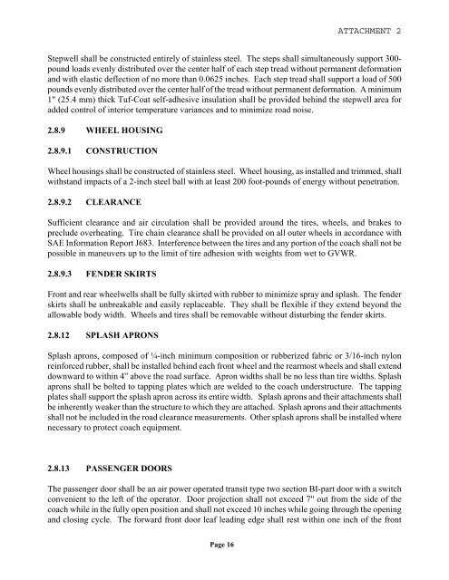
Stepwell shall be constructed entirely of stainless steel. The steps shall simultaneously support 300pound<br />
loads evenly distributed over the center half of each step tread without permanent deformation<br />
and with elastic deflection of no more than 0.0625 inches. Each step tread shall support a load of 500<br />
pounds evenly distributed over the center half of the tread without permanent deformation. A minimum<br />
1" (25.4 mm) thick Tuf-Coat self-adhesive insulation shall be provided behind the stepwell area for<br />
added control of interior temperature variances and to minimize road noise.<br />
2.8.9 WHEEL HOUSING<br />
2.8.9.1 CONSTRUCTION<br />
Wheel housings shall be constructed of stainless steel. Wheel housing, as installed and trimmed, shall<br />
withstand impacts of a 2-inch steel ball with at least 200 foot-pounds of energy without penetration.<br />
2.8.9.2 CLEARANCE<br />
Sufficient clearance and air circulation shall be provided around the tires, wheels, and brakes to<br />
preclude overheating. Tire chain clearance shall be provided on all outer wheels in accordance with<br />
SAE Information Report J683. Interference between the tires and any portion of the <strong>coach</strong> shall not be<br />
possible in maneuvers up to the limit of tire adhesion with weights from wet to GVWR.<br />
2.8.9.3 FENDER SKIRTS<br />
Front and rear wheelwells shall be fully skirted with rubber to minimize spray and splash. The fender<br />
skirts shall be unbreakable and easily replaceable. They shall be flexible if they extend beyond the<br />
allowable body width. Wheels and tires shall be removable without disturbing the fender skirts.<br />
2.8.12 SPLASH APRONS<br />
Splash aprons, composed of ¼-inch minimum composition or rubberized fabric or 3/16-inch nylon<br />
reinforced rubber, shall be installed behind each front wheel and the rearmost wheels and shall extend<br />
downward to within 4” above the road surface. Apron widths shall be no less than tire widths. Splash<br />
aprons shall be bolted to tapping plates which are welded to the <strong>coach</strong> understructure. The tapping<br />
plates shall support the splash apron across its entire width. Splash aprons and their <strong>attachment</strong>s shall<br />
be inherently weaker than the structure to which they are attached. Splash aprons and their <strong>attachment</strong>s<br />
shall not be included in the road clearance measurements. Other splash aprons shall be installed where<br />
necessary to protect <strong>coach</strong> equipment.<br />
2.8.13 PASSENGER DOORS<br />
The passenger door shall be an air power operated transit type two <strong>section</strong> BI-part door with a switch<br />
convenient to the left of the operator. Door projection shall not exceed 7" out from the side of the<br />
<strong>coach</strong> while in the fully open position and shall not exceed 10 inches while going through the opening<br />
and closing cycle. The forward front door leaf leading edge shall rest within one inch of the front