attachment 2 section i ? technical specifications commuter coach ...
attachment 2 section i ? technical specifications commuter coach ...
attachment 2 section i ? technical specifications commuter coach ...

You also want an ePaper? Increase the reach of your titles
YUMPU automatically turns print PDFs into web optimized ePapers that Google loves.
Page 45<br />
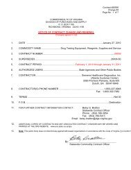
ATTACHMENT 2<br />
The steering wheel shall be not less than 19.5 inches in diameter and shall be shaped for firm grip with<br />
comfort for long periods of time and shall not be padded. The steering wheel shall be removable with a<br />
standard or universal puller. Hydraulically assisted power steering shall be provided. The steering gear<br />
shall be an integral type with flexible lines eliminated or the number and length minimized. Steering<br />
torque applied by the driver shall not exceed 10-foot-pounds with the front wheels straight ahead to<br />
turned 10 degrees. Steering torque may increase to 70-foot-pounds when the wheels are approaching<br />
the steering stops. Steering effort shall be measured with the <strong>coach</strong> at SLW, stopped with the brakes<br />
released and the engine at normal idling speed on clean, dry, level, commercial asphalt pavement and<br />
the tires inflated to recommended pressure. Power steering failure shall not result in loss of steering<br />
control. With the <strong>coach</strong> in operation, the steering effort shall not exceed 55 pounds at the steering<br />
wheel rim and perceived free play in the steering system shall not materially increase as a result of<br />
power assist failure.<br />
Caster angle shall be selected to provide a tendency for the return of the front wheels to the straight<br />
position with minimal assistance from the driver.<br />
3.5 BRAKES<br />
3.5.1 SERVICE BRAKE<br />
3.5.1.1 ACTUATION<br />
Service brakes shall be controlled and actuated by an air system. Force to activate the brake pedal<br />
control shall be an essentially linear function of the <strong>coach</strong> deceleration rate. The angle of the pedal<br />
shall be ergonomically designed to minimize fatigue. At least six (6") inches of slack in the airlines<br />
shall be available to allow for change out of the brake treadle valve and pedal assembly. The brake<br />
pedal shall be slightly lower than the accelerator. Provisions at the front shall be made to activate the<br />
brakes from the towing vehicle. Release of the emergency/parking brake shall require one full<br />
application of the service brake once the emergency/parking brake release valve is depressed. A<br />
protective bracket shall be added to the secondary emergency release valve.<br />
3.5.1.2 FRICTION MATERIAL<br />
Brake lining shall be non-asbestos Carlisle brake lining, and must be designed and approved for use on<br />
the vehicle being proposed. All brake linings shall be standard tapered Q-Plus lining. Brake lining<br />
must provide optimum performance with the brake system being used and shall minimize brake noise<br />
under all weather conditions. Riveted linings are acceptable. The brake system shall be equipped with<br />
Meritor, automatic slack adjusters.<br />
3.5.1.3 HUBS AND DRUMS<br />
Wheel bearing seals shall have integral replaceable wear surfaces. Wheel bearings and hubs shall be oil<br />
lubricated. Use of disc brakes shall not be permitted on any axle.<br />
3.5.1.4 ANTILOCK BRAKE SYSTEM