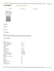
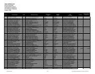
attachment 2 section i ? technical specifications commuter coach ...
attachment 2 section i ? technical specifications commuter coach ...
attachment 2 section i ? technical specifications commuter coach ...

Create successful ePaper yourself
Turn your PDF publications into a flip-book with our unique Google optimized e-Paper software.
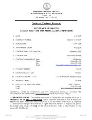
Page 55<br />
ATTACHMENT 2<br />
An internal ventilation system with individualized air outlets shall be provided and connected directly<br />
to the main heat/AC air distribution system, to provide conditioned or recirculated air at each twopassenger<br />
seat. Individual air outlets shall be mounted in the console at the underside of parcel racks.<br />
Outlets shall be passenger controlled by twisting off or on, and by directing the air flow. Air shall enter<br />
the power ventilation system through inlet vents.<br />
A separate control shall be provided for the front dash heating and air conditioning, as well as for the<br />
main underfloor unit. A rheostat control is required for the main underfloor system. Control shall be<br />
within easy reach of the operator. System shall allow the driver to set a specific interior <strong>coach</strong><br />
temperature within an approximate 20° F (11°C) range. The outside temperature can be displayed by<br />
pressing a knob on the thermostat. The HVAC controller shall monitor the temperature so that the<br />
interior temperature selected is maintained consistently. All controls shall be solid state designs.<br />
The system shall be designed with return air ducts at both front and rear of <strong>coach</strong> for balanced airflow.<br />
The system shall introduce a minimum of 10% fresh outside air when the fresh air intake is open.<br />
Heat shall be applied to the front step tread to prevent accumulation of snow, ice, or slush. Stepwell<br />
heat shall be supplied and controlled by the driver's heater and defroster system. The manufacturer<br />
shall provide and install two Schraeder or MADDEN valves with caps near the air conditioning<br />
compressor.<br />
All electric motors which are part of the climate control system, except the evaporator motor, shall be<br />
permanent magnet type. Motors shall have double sealed, pre-lubricated anti-friction, replaceable ball<br />
bearings with moisture resistant grease. 3/8 and 5/16 diameter zinc terminal studs with bonded internal<br />
motor leads and anti-rotation insulators shall be used except driver’s evaporator and parcel rack<br />
evaporators.<br />
3.7.2 CONTROLS<br />
The heating, cooling, ventilating and off operational modes of the interior climate control system shall<br />
be controlled by switches conveniently located to the driver. In the heating and cooling modes, the<br />
system shall be governed by a linear potentiometer control that regulates the amount of cooling and<br />
heating capacity available to the passenger area. The temperature will be completely adjustable<br />
between 60°F and 80°F. The temperature sensors used must be suitable for transit service and accurate<br />
to +/- 1°F. All system controls shall be solid state designs.<br />
3.7.3 AIR FLOW<br />
3.7.3.1 PASSENGER AREA<br />
The cooling mode of the interior climate control system shall introduce air into the <strong>coach</strong> up along the<br />
sidewall at a minimum rate of 25 cubic feet per minute per passenger based on the standard<br />
configuration <strong>coach</strong> with full standee load. This air shall be composed of no less than 10 percent<br />
outside air. Airflow shall be evenly distributed throughout the <strong>coach</strong> with air velocity not exceeding 60<br />
feet per minute on any passenger.