Chapter 4 Vortex detection - Computer Graphics and Visualization
Chapter 4 Vortex detection - Computer Graphics and Visualization
Chapter 4 Vortex detection - Computer Graphics and Visualization

You also want an ePaper? Increase the reach of your titles
YUMPU automatically turns print PDFs into web optimized ePapers that Google loves.
3.2 Particle tracing in curvilinear grids<br />
3.2.1 Curvilinear grids<br />
3.2. Particle tracing in curvilinear grids<br />
In practice, many CFD applications do not use uniform grids, but structured curvilinear<br />
grids, consisting of deformed, hexahedral cells, with curved faces (see also Section 2.1).<br />
An advantage of curvilinear grids is their ability to conform to the shape of curved<br />
or complex geometries, such as airplane wings <strong>and</strong> coast lines. Another advantage<br />
is their regular topological structure, so the cells <strong>and</strong> data are addressable through indices<br />
( . A disadvantage of these grids is that algorithms working in them become<br />
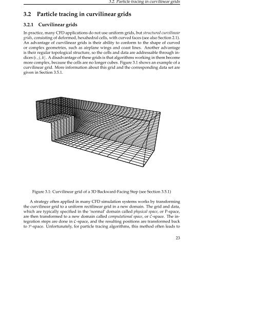
more complex, because the cells are no longer cubes. Figure 3.1 shows an example of a<br />
curvilinear grid. More information about this grid <strong>and</strong> the corresponding data set are<br />
given in Section 3.5.1.<br />
Figure 3.1: Curvilinear grid of a 3D Backward-Facing Step (see Section 3.5.1)<br />
A strategy often applied in many CFD simulation systems works by transforming<br />
the curvilinear grid to a uniform rectilinear grid in a new domain. The grid <strong>and</strong> data,<br />
which are typically specified in the ‘normal’ domain called physical space, or P-space,<br />
are then transformed to a new domain called computational space, or-space. The integration<br />
steps are done in -space, <strong>and</strong> the resulting positions are transformed back<br />
to È-space. Unfortunately, for particle tracing algorithms, this method often leads to<br />
23