- Page 1:
This manual has been prepared by DE
- Page 4 and 5:
Engine Number of cylinders ........
- Page 6 and 7:
6 REGULAR MAINTENANCE TABLE Períod
- Page 8 and 9:
HUNTER MODELS Stripping the fork le
- Page 10 and 11:
STRIPPING - Remove the luggage carr
- Page 12 and 13:
- Remove the stator (2 screws): in
- Page 14 and 15:
- In order to extract the water pum
- Page 16 and 17:
- Assembly of the wheel shaft beari
- Page 18 and 19:
- Measure the lateral play at the c
- Page 20 and 21:
Stripping - Unscrew the water pump
- Page 22 and 23:
- The working surfaces of the pulle
- Page 24 and 25:
- Fit the clutch hub onto the pulle
- Page 26 and 27:
- Fit the oil pump with 2 screws 5
- Page 28 and 29:
- The cylinders of the monobloc mod
- Page 30 and 31:
Stripping the carburettor - Remove
- Page 32 and 33:
Carburettors Make Dell’orto Dell
- Page 34 and 35:
- Fit the cooling hose from the wat
- Page 36 and 37:
GENERAL CHARACTERISTICS Component B
- Page 38 and 39:
Charging the battery for the first
- Page 40 and 41:
SCHEMATIC AND IGNITION CIRCUIT CONT
- Page 42 and 43:
Connection of lighting switch, turn
- Page 44 and 45:
SCHEMATIC AND CARBURETTOR HEATING C
- Page 46 and 47:
46 ECHEMA ELECTRIQUE HUNTER Orange
- Page 48 and 49:
ANNEXE PREDATOR-LC - CAT - WVTA Mod
- Page 50 and 51:
TORQUE SETTINGS PART NAME TORQUE SE
- Page 52 and 53:
For all ATLANTIS models, hydraulic
- Page 54 and 55:
ATLANTIS LC: - Hydraulic shock abso
- Page 56 and 57:
CHECKING THE IGNITION Inspecting th
- Page 58 and 59:
CYLINDER HEAD Compression Ratio: 11
- Page 60 and 61: Adjustment Table BRAND CARBURETOR M
- Page 62 and 63: CHECKING THE ELECTRICAL SYSTEM IN T
- Page 64 and 65: 65 ECHEMA ELECTRIQUE PREDATOR Orang
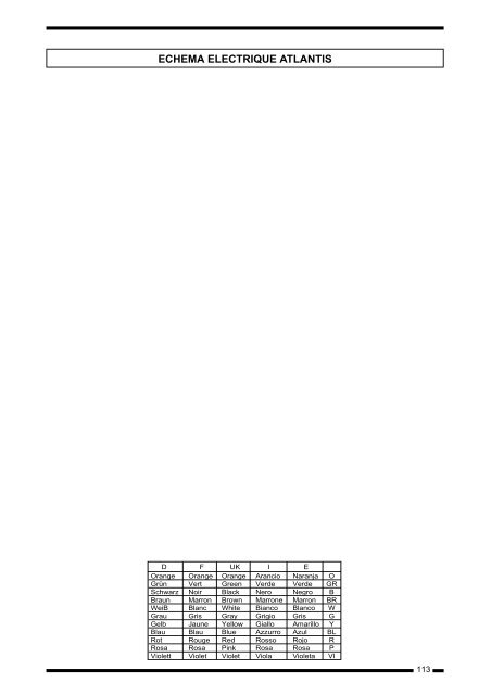
- Page 66 and 67: 67 ECHEMA ELECTRIQUE ATLANTIS Orang
- Page 68 and 69: ECHEMA ELECTRIQUE ATLANTIS (USA) D
- Page 70 and 71: ECHEMA ELECTRIQUE ATLANTIS 100 D F
- Page 72 and 73: 74 SPECIAL TOOLS Description Refere
- Page 74 and 75: 76 SPECIAL TOOLS Description Refere
- Page 76 and 77: DESCRIPTION TORQUE SETTING Nw x m C
- Page 78 and 79: Suspension stroke .................
- Page 80 and 81: Starter motor - The securing nuts a
- Page 82 and 83: SYMBOL 84 LUBRICATE GREASE QUANTITY
- Page 84 and 85: Movil semi pulley - Remove the thre
- Page 86 and 87: Clutch - Remove the central nut whi
- Page 88 and 89: Re-assembly of the clutch - Refit t
- Page 90 and 91: Follower pulley shaft oil seal - St
- Page 92 and 93: Mating the crankcase halves - Apply
- Page 94 and 95: Thermostat - cylinder head - by-pas
- Page 96 and 97: SYMBOL 98 LUBRICATE GREASE QUANTITY
- Page 98 and 99: Disassembling the seal Common tools
- Page 100 and 101: SYMBOL 102 LUBRICATE GREASE QUANTIT
- Page 102 and 103: SYMBOL 104 LUBRICATE GREASE QUANTIT
- Page 104 and 105: Piston Caution! Position the arrow
- Page 106 and 107: Piston Rings - The verification of
- Page 108 and 109: Crankshaft alignment check - Using
- Page 112 and 113: 114 ECHEMA ELECTRIQUE GP1 Orange Gr
- Page 114: 116 ECHEMA ELECTRIQUE GP Series D F