4 WinCC-Runtime 4.1 Start of the program without Auto Start
4 WinCC-Runtime 4.1 Start of the program without Auto Start
4 WinCC-Runtime 4.1 Start of the program without Auto Start

You also want an ePaper? Increase the reach of your titles
YUMPU automatically turns print PDFs into web optimized ePapers that Google loves.
Do <strong>the</strong> pressure test carefully before first usage.<br />
4 <strong>WinCC</strong>-<strong>Runtime</strong><br />
<strong>4.1</strong> <strong>Start</strong> <strong>of</strong> <strong>the</strong> <strong>program</strong> <strong>without</strong> <strong>Auto</strong> <strong>Start</strong><br />
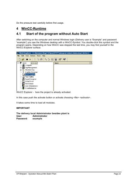
After switching on <strong>the</strong> computer and normal Windows login (Delivery user is “Example” and password<br />
“example”) you see <strong>the</strong> Windows desktop with a <strong>WinCC</strong>-Symbol. You double-click this symbol and <strong>the</strong><br />
<strong>program</strong> opens. Depending on how <strong>WinCC</strong> was stopped <strong>the</strong> last time, you may find yourself in <strong>the</strong><br />
<strong>WinCC</strong>-Explorer surface.<br />
<strong>WinCC</strong> Explorer - here <strong>the</strong> project is already activated.<br />
In this case push <strong>the</strong> activate button or activate choosing .<br />
It takes some time to load all modules.<br />
IMPORTANT<br />
The delivery local Administrator besides plant is<br />
User: Administrator<br />
Password: example<br />
AP-Miniplant - Operation Manual Mini Batch Plant Page 23
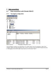
4.2 Overview picture<br />
Overview picture with push buttons at <strong>the</strong> bottom line, process flow sheet and actuators and control<br />
loops which can be clicked on.<br />
The push buttons have <strong>the</strong> following meaning:<br />
Label Meaning<br />
Dummy For maintenance only, switches to an empty picture<br />
Recipe Shows <strong>the</strong> recipe pop up window<br />
(Stop Recipe) Stops <strong>the</strong> recipe<br />
Recipe Shows <strong>the</strong> recipe pop up window<br />
Shut down <strong>Start</strong>s <strong>the</strong> shut down procedure to bring <strong>the</strong> process into a save state<br />
Sample Opens <strong>the</strong> sampling pop up window<br />
(Sample ack.) Must be pressed after <strong>the</strong> sampling vial is placed to allow sampling<br />
Pres. Test Evaluates <strong>the</strong> presser test<br />
Inert Evaluates intertisation<br />
Curves Shows different curves <strong>of</strong> measured values<br />
Safety Shows safety settings<br />
Symbol Key <strong>Start</strong>s login procedure, opens safety settings first.<br />
Symbol Exit Exits this <strong>program</strong>, a safety question follows.<br />
DANGER<br />
Exiting <strong>the</strong> <strong>program</strong> before <strong>the</strong> plant is in a safe state is dangerous. The plant cannot be<br />
operated <strong>without</strong> <strong>the</strong> <strong>program</strong>. Press <strong>the</strong> shut down button or emergency <strong>of</strong>f in case <strong>of</strong> danger<br />
AP-Miniplant - Operation Manual Mini Batch Plant Page 24
if no <strong>program</strong> is started. If for some reason <strong>the</strong> system does not react on you interaction, you<br />
have <strong>the</strong> same situation.<br />
4.3 Alarm picture<br />
Alarm window in <strong>the</strong> top left region <strong>of</strong> <strong>the</strong> overview window<br />
The alarm window has <strong>the</strong> following buttons (left to right):<br />
Message list<br />
Shows <strong>the</strong> active messages and those which are not acknowledged<br />
Short term archive Shows <strong>the</strong> last messages, even if <strong>the</strong>y are not active any more.<br />
Ind. Ackn. Acknowledges this single message.<br />
Group Ackn. Acknowledges all messages<br />
Scroll on/<strong>of</strong>f Allows to select single messages in scroll mode.<br />
Alarm window buttons<br />
Please note <strong>the</strong> following colour scheme:<br />
Alarm/status Came in Went out acknowledged<br />
Text/background Text/background Text/background<br />
Alarm white/red black/green red/white<br />
Warning white/orange blue/grey orange/white<br />
Failure black/yellow black/white yellow/grey<br />
Colour combinations in <strong>the</strong> alarm window<br />
Messages which are gone, but not acknowledged, remain in <strong>the</strong> message list, and change <strong>the</strong> colours<br />
to those indicated in <strong>the</strong> “Went out”-column. Acknowledged messages which went out are erased from<br />
<strong>the</strong> message list. The remain in <strong>the</strong> short term archive list.<br />
4.4 Shut down<br />
In case <strong>of</strong> emergency <strong>the</strong> predefined shut down procedure shall bring <strong>the</strong> plant into a safe state.<br />
4.<strong>4.1</strong> <strong>Start</strong> shut down procedure<br />
This procedure can be started by<br />
Pressing <strong>the</strong> shut down button on <strong>the</strong> window and answering <strong>the</strong> question “Do you really want to start<br />
<strong>the</strong> shut down procedure?<br />
Pressing <strong>the</strong> yellow push button at <strong>the</strong> PC-Cabinet or at <strong>the</strong> rig.<br />
AP-Miniplant - Operation Manual Mini Batch Plant Page 25
One <strong>of</strong> <strong>the</strong> events shown in <strong>the</strong> following list:<br />
Hydrogen alarm (immediately after signal changes from 1 to 0)<br />
Extraction failure (70 s after event, 1st warning after 10 s)<br />
Fire extinguisher on (immediately after signal changes from 1 to 0)<br />
Emergency <strong>of</strong>f push button (immediately after signal changes from 1 to 0)<br />
Safety questions after starting<br />
shut down<br />
Warning message in <strong>the</strong> alarm window, at <strong>the</strong> same time <strong>the</strong><br />
button starts flashing while <strong>the</strong> shut down<br />
procedure is active.<br />
The shut down procedure brings <strong>the</strong> reactor to a safe temperature. During this procedure <strong>the</strong> stirrer<br />
will go to a predefined safe stirrer speed if it was switched on before <strong>the</strong> shut down procedure started.<br />
After reaching <strong>the</strong> safe temperature, <strong>the</strong> reactor will be vented. All feeds are blocked.<br />
4.4.2 Stop shut down procedure<br />
The shut down procedure has to be stopped manually by pushing <strong>the</strong> shut down button again and<br />
answering <strong>the</strong> safety question with .<br />
Shut down procedure can also be stopped pressing <strong>the</strong> Button at <strong>the</strong> rig or <strong>the</strong> PC<br />
cabinet for more <strong>the</strong>n 3 seconds.<br />
4.5 Locking mechanism<br />
4.5.1 Valves<br />
Hydrogen input V17 is blocked as long as no pressure test has been successfully performed.<br />
Vacuum/Normal pressure valve H04 will switch automatically to normal pressure as soon as <strong>the</strong> limit<br />
<strong>of</strong> 1.2 bar is exceeded.<br />
Catalyst Feed H01<br />
Acknowledge button catalyst feed<br />
To prevent <strong>the</strong> catalyst feed from being used by mistake, <strong>the</strong>re<br />
is a locking mechanism. It is necessary to acknowledge with a<br />
button that <strong>the</strong> catalyst unit is properly prepared for use. This<br />
button has to be pressed after every opening <strong>of</strong> <strong>the</strong> ball valve<br />
H01.<br />
AP-Miniplant - Operation Manual Mini Batch Plant Page 26
V30 and V04 are blocked during vacuum operation (blocked < 880 mbar, released > 950 mbar)<br />
Distillate vessel high level reached: H21 is closed and H20 opens<br />
V10 can not be opened if V39 is open and vice versa.<br />
4.5.2 Controller priorities<br />
Priority settings for <strong>the</strong> feed vessel are:<br />
purge with overpressure<br />
Dosing<br />
Pressure control<br />
Priority settings for <strong>the</strong> reactor vessel are:<br />
pressure test<br />
purge with vacuum support<br />
Overpressure control PIC01<br />
Gas Feed FIC01<br />
Vacuum control PIC02<br />
In any case if an action with higher priority is performed, one with a lower priority can not be started.<br />
4.5.3 O<strong>the</strong>rs<br />
Solid dosing is only possible between 0.9 and 1.1 bar abs. (PIC01).<br />
Solid dosing will be stopped if low limit is reached.<br />
Liquid feed will be stopped if low limit is reached.<br />
The shut down procedure stops <strong>the</strong> recipe.<br />
4.6 Login<br />
Without login you cannot operate <strong>the</strong> plant. Please use <strong>the</strong> key symbol for <strong>the</strong> login procedure. You<br />
will see <strong>the</strong> safety settings first. This is to ensure that every new user knows <strong>the</strong> current safety<br />
settings. You have to push <strong>the</strong> key symbol on this screen again to get into <strong>the</strong> login picture.<br />
AP-Miniplant - Operation Manual Mini Batch Plant Page 27
Safety settings<br />
Login window<br />
In delivery state <strong>the</strong> following logins are predefined:<br />
Operator “example” password “example”<br />
Administrator: “example” password “example”<br />
You may change <strong>the</strong>se logins using <strong>the</strong> user administrator in <strong>the</strong> <strong>WinCC</strong> explorer. (see CD-Handbook<br />
for this procedure)<br />
AP-Miniplant - Operation Manual Mini Batch Plant Page 28
You can close both windows by clicking on <strong>the</strong> cross in <strong>the</strong> top right corner. You can also do so by<br />
pressing respective .<br />
4.7 Weight button<br />
The weight button allows you to adjust <strong>the</strong> balances. Normally only <strong>the</strong> -button is used.<br />
Balance readjustment should only be made if necessary. Follow <strong>the</strong> points on <strong>the</strong> screen to do this.<br />
You will need suitable reference weights for this purpose.<br />
When leaving this adjustment window, a warning will be displayed about <strong>the</strong> risk <strong>of</strong> wrong adjustment<br />
<strong>of</strong> <strong>the</strong> balance.<br />
Distillation, input <strong>the</strong> max. weight<br />
which is 2 l/density. The capacity<br />
is necessary for on line level<br />
display.<br />
The feed vessel has <strong>the</strong> same<br />
input values.<br />
screen (left) and balance adjustment screen (top)<br />
Reactor, feed vessel is <strong>the</strong><br />
same picture. Please enter <strong>the</strong><br />
volume where you want <strong>the</strong><br />
high alarm and <strong>the</strong> density.<br />
Manipulation <strong>of</strong> valves<br />
When clicking on an automatic valve, <strong>the</strong> following screen will appear:<br />
Solid feed: The correct setting<br />
is dependent from if you have<br />
a lid on it and what <strong>the</strong> dead<br />
volume is.<br />
AP-Miniplant - Operation Manual Mini Batch Plant Page 29
Closed and open valve<br />
Clicking on <strong>the</strong> or button will open/close <strong>the</strong> valve. Left from <strong>the</strong> button you can see<br />
<strong>the</strong> current status <strong>of</strong> <strong>the</strong> valves.<br />
If <strong>the</strong>re are safety settings that do not allow opening <strong>the</strong> valve, it is not possible to switch <strong>the</strong>m<br />
manually.<br />
4.8 Controllers<br />
Continuous valves have to be switched on to operate <strong>the</strong>m. The set point can be<br />
given by <strong>the</strong> slider bar or as a numerical value in <strong>the</strong> input field above <strong>the</strong> slider<br />
bar.<br />
Controllers are chosen when clicking at <strong>the</strong> controlled value in <strong>the</strong> overview screen.<br />
The following table gives an overview:<br />
AP-Miniplant - Operation Manual Mini Batch Plant Page 30
Loop Function Actuator Range I-share<br />
on<br />
D-share<br />
on<br />
KP TI TD<br />
FIC01 Gas Feed V01 0-4<br />
NL/h<br />
- - - - -<br />
FIC02 Liquid feed V28/30/ 1.5 150 Yes No 2.5 *20.0 *<br />
V31, H07, g/min<br />
H03<br />
FIC04 Solid feed Motor 1.5 150 Yes No 10 15 0<br />
solid<br />
feeder<br />
g/min<br />
GS01 Reflux divider H20<br />
H21<br />
0-100% - - - - -<br />
PIC01 Pressure<br />
controller<br />
FIC01 1-20 bar Yes No 5 10 0<br />
PIC02 Pressure Vacuum 0-1100 Yes No 10 15 4<br />
controller pump mbar<br />
PIC03 Pressure V28/30/ 0-20 bar No No Hys. - -<br />
controller V31, H07<br />
0.1 bar<br />
PIS06 Pressure before V25-26 1-20 bar N0 No Hys. - -<br />
Feed<br />
1 bar<br />
SIC01 Stirrer speed Stirrer 30-1500 - - - - -<br />
motor Rpm<br />
TIC01 Temperature<br />
reactor<br />
HCS02 -40-200 Yes No 2 900 0<br />
TIC01L Temperature<br />
Reactor (liquid)<br />
HCS02 -40-200 Yes No * * *<br />
TIC01S Temperature<br />
Reactor (solid)<br />
HCS02 -40-200 Yes No * * *<br />
TIC02 Temperature<br />
feed<br />
HCS01 -20-100 Yes No 1.1 620 6<br />
TIS03 Partial<br />
condenser<br />
V22 0-200 Yes No 5.0 30.0 *<br />
TIS07 Accompanied El. 0-100 No No Hys. 3 - -<br />
Heating heating<br />
°C<br />
Overview controller and its settings.<br />
Attention: Not all settings in this table have to be optimal ones for your special requirements.<br />
The structures <strong>of</strong> <strong>the</strong> controller are as follows:<br />
Standard controller<br />
The standard controller picture is shown left.<br />
There is a bar graph and a numerical field left.<br />
Then <strong>the</strong>re is a slider bar and a numerical field<br />
above for <strong>the</strong> set point input. The tick box<br />
activates <strong>the</strong> controller for manual and automatic<br />
operation. In manual mode <strong>the</strong> set point value is<br />
directly given to <strong>the</strong> actuator. The tick<br />
box switches <strong>the</strong> controller to automatic mode. and allow a change<br />
between controller structures.<br />
AP-Miniplant - Operation Manual Mini Batch Plant Page 31
Structure I-share on D-share on Used constants<br />
P-controller Off Off KP<br />
PI-controller On Off KP, TI<br />
PID-controller On On KP, TI, TD<br />
Controller structures<br />
WARNING (concerning all controllers)<br />
The o<strong>the</strong>r settings , and <strong>the</strong> PID-controller constants KP, TI and TD should<br />
only be changed if you have expert knowledge about PID controllers.<br />
4.8.1 Feed controller FIC 01- 03<br />
Gas Feed FIC01<br />
The gas feed line can be switched on and <strong>of</strong>f by<br />
clicking <strong>the</strong> “On” checkbox. In <strong>the</strong> case <strong>of</strong> <strong>the</strong><br />
mass flow controller, <strong>the</strong> controller itself is inside<br />
<strong>the</strong> sensor valve system. The slider bar or <strong>the</strong><br />
numerical field above can give <strong>the</strong> set point <strong>of</strong> this<br />
MFC.<br />
DANGER:<br />
Always make sure that <strong>the</strong> system is tight<br />
before hydrogen can be added.<br />
IMPORTANT:<br />
Controller can only be used after a successful<br />
pressure test.<br />
Liquid Feed FIC02<br />
Liquid feed is operated as a standard controller.<br />
Exception: The “press.” setting in <strong>the</strong> right bottom<br />
field will determine <strong>the</strong> pressure difference to <strong>the</strong><br />
reactor. The flow will start automatically after this<br />
pressure difference is reached. PIC03 is used for<br />
this purpose.<br />
The minimum set point should not be less <strong>the</strong>n<br />
1.5 g/min.<br />
Make sure that <strong>the</strong> liquid feed tank is filled before<br />
you start dosing. Low level alarm detection will<br />
switch <strong>of</strong>f <strong>the</strong> liquid feed controller.<br />
AP-Miniplant - Operation Manual Mini Batch Plant Page 32
4.8.2 Reflux divider GS 01<br />
GS 01: Reflux divider via H20 and H21<br />
4.8.3 Pressure controller PIC 01<br />
Solid Feed FIC04<br />
Solid feed is operated as a standard controller.<br />
It is necessary to have <strong>the</strong> hopper properly filled<br />
for <strong>the</strong> dosing <strong>of</strong> solids. When <strong>the</strong> “hopper empty”<br />
level is reached, this controller will be switched<br />
<strong>of</strong>f.<br />
Choose <strong>the</strong> right size <strong>of</strong> <strong>the</strong> discharge tube<br />
appropriate to <strong>the</strong> dosing speed.<br />
The divider can be adjusted between 0 – 100 %<br />
reflux. 100 % means that no distillate will reach <strong>the</strong><br />
distillate vessel.<br />
The process value is <strong>the</strong> position <strong>of</strong> <strong>the</strong> divider<br />
which can be ei<strong>the</strong>r 0 % or 100 % (reflux = H20<br />
open or distillate H21 open).<br />
The reflux divider itself can ei<strong>the</strong>r be open or<br />
closed. The reflux ratio is a ratio between open H20<br />
and H21 closed and <strong>the</strong> time H20 is closed and H21<br />
open. The time basis for <strong>the</strong> divider is 20 Sec., that<br />
means that changes made to <strong>the</strong> ratio will need up<br />
to 20 seconds until <strong>the</strong>re is an effect. Minimum value<br />
is 5 %!<br />
Overpressure controller PIC 01<br />
PIC01 is operated as a standard controller.<br />
It uses Hydrogen to raise <strong>the</strong> pressure level. In<br />
case <strong>of</strong> a pressure > set point + 0.25 bar it will<br />
open V04 with a maximum opening <strong>of</strong> 20 %. If <strong>the</strong><br />
delta p is smaller, <strong>the</strong> pressure reduction has to be<br />
done by hydrogen consumption during <strong>the</strong><br />
reaction.<br />
To prevent over swinging, <strong>the</strong>re is a hard limit<br />
when pressure > set point + 0.1 bar. In this case<br />
<strong>the</strong> hydrogen mass flow controller set point will be<br />
set to 0.<br />
IMPORTANT:<br />
AP-Miniplant - Operation Manual Mini Batch Plant Page 33
Controller can only be used after a successful<br />
pressure test.<br />
Vacuum controller PIC 02<br />
PIC02 is operated as a standard controller.<br />
It uses <strong>the</strong> variable speed vacuum pump to control<br />
<strong>the</strong> pressure. To raise <strong>the</strong> pressure it can open <strong>the</strong><br />
nitrogen valve V10. To ensure that <strong>the</strong> line is<br />
open, <strong>the</strong> manual valve V42 must be open and<br />
FI06 should show a flow rate when both valves are<br />
open.<br />
Only if <strong>the</strong> ball valve H04 is connected to <strong>the</strong><br />
vacuum pump, <strong>the</strong> vacuum is applied to <strong>the</strong><br />
reactor.<br />
In case <strong>of</strong> manual operation <strong>the</strong> set point will be<br />
scaled in percent and control <strong>the</strong> vacuum pump<br />
directly. In automatic mode it gives <strong>the</strong> value <strong>the</strong><br />
system will try to reach automatically.<br />
WARNING<br />
Switching <strong>of</strong>f <strong>the</strong> automatic mode with a high<br />
set point will cause <strong>the</strong> vacuum pump to run<br />
with high speed which can cause unwanted<br />
evaporation in <strong>the</strong> system. Switch <strong>of</strong>f <strong>the</strong> <br />
checkbox instead.<br />
Feed vessel pressure PIC 03<br />
This controller can only work with a hysteresis,<br />
which has to be given in <strong>the</strong> appropriate field.<br />
Hysteresis should not be less <strong>the</strong>n 0.1 bar.<br />
The pressurizing will always be through V28 with<br />
nitrogen. In case <strong>of</strong> overpressure, <strong>the</strong> pressure<br />
reduction will be done through V30 directly into <strong>the</strong><br />
vent line. In case <strong>of</strong> vacuum in <strong>the</strong> reactor <strong>the</strong><br />
pressure reduction will be done through V31 and<br />
H07 into <strong>the</strong> reactor vent system.<br />
To evacuate <strong>the</strong> feed vessel and <strong>the</strong> reactor, <strong>the</strong><br />
set point has to be set to 0.<br />
AP-Miniplant - Operation Manual Mini Batch Plant Page 34
4.8.4 Stirrer Speed control for RM 02<br />
RM 01: Stirrer speed control<br />
4.8.5 Temperature controller<br />
Compressor controller PIS 06<br />
PIC06 can be used to control approximately <strong>the</strong><br />
pressure after <strong>the</strong> compressor. This is done by <strong>the</strong><br />
nitrogen inlet valve V25 and <strong>the</strong> outlet valve V26.<br />
The set point is given like in <strong>the</strong> standard<br />
controller.<br />
The parameter you can give <strong>the</strong> controller is <strong>the</strong><br />
hysteresis between upper and lower pressure. We<br />
recommend a value <strong>of</strong> 1.0 bar for <strong>the</strong> hysteresis.<br />
The stirrer can be switched on and <strong>of</strong>f with<br />
<strong>the</strong> click box. Use <strong>the</strong> slider bar or <strong>the</strong><br />
numeric field above it to change <strong>the</strong> stirrer<br />
speed.<br />
AP-Miniplant - Operation Manual Mini Batch Plant Page 35
Reactor temperature TIC 01<br />
TIC01 is operated as a standard controller<br />
with one exception:<br />
Tick box instead <strong>of</strong><br />
with <strong>the</strong> following meaning:<br />
= Off means <strong>the</strong> set point will<br />
be <strong>the</strong> one for <strong>the</strong> oil temperature.<br />
= On means that <strong>the</strong> set<br />
point refers to <strong>the</strong> temperature inside <strong>the</strong><br />
reactor.<br />
Reactor temperature TIC 01L and TIC 01S<br />
by liquid and solid feed.<br />
TIC01L and TIC01S are operated as a<br />
standard controller with one exception:<br />
A set point for <strong>the</strong> flow rate can be given in<br />
<strong>the</strong> field . This set point is <strong>the</strong> basis<br />
flow <strong>the</strong> controller starts with. It should be <strong>the</strong><br />
equilibrium flow rate at this temperature.<br />
Feed vessel temperature TIC 02<br />
TIC02 is operated as a standard controller<br />
with one exception:<br />
Tick box instead <strong>of</strong><br />
with <strong>the</strong> following meaning:<br />
= Off means <strong>the</strong> set point will<br />
be <strong>the</strong> one for <strong>the</strong> oil temperature.<br />
= On means that <strong>the</strong> set<br />
point refers to <strong>the</strong> temperature inside <strong>the</strong><br />
feed vessel.<br />
AP-Miniplant - Operation Manual Mini Batch Plant Page 36
Part. Condenser Head temp. TIS 03<br />
TIC03 is operated as a standard controller.<br />
Opening <strong>the</strong> water supply <strong>of</strong> <strong>the</strong> cooling<br />
jacket via solenoid valve V22 controls <strong>the</strong><br />
temperature above <strong>the</strong> partial condenser.<br />
The manual control valve V32 should be<br />
adjusted so that <strong>the</strong> flow rate for <strong>the</strong><br />
condenser is nei<strong>the</strong>r too big nor too small.<br />
Accompanied heating TIS 07<br />
TIS07 is a simple on/<strong>of</strong>f accompanied<br />
heating controller for <strong>the</strong> feed line.<br />
The temperature sensor is outside <strong>the</strong> tube at<br />
its wall.<br />
Hysteresis means <strong>the</strong> difference between <strong>the</strong><br />
2 switching points on and <strong>of</strong>f.<br />
AP-Miniplant - Operation Manual Mini Batch Plant Page 37
4.9 On-line trend<br />
Trend selection Trend curves <strong>of</strong> temperatures<br />
Pressing <strong>the</strong> button in <strong>the</strong> <strong>WinCC</strong>-<strong>Runtime</strong>-window will open <strong>the</strong> trend selection window.<br />
From here you get to <strong>the</strong> trend-windows as specified on <strong>the</strong> button. On <strong>the</strong> top <strong>of</strong> <strong>the</strong> trend-window<br />
<strong>the</strong>re are some buttons to control <strong>the</strong> appearance <strong>of</strong> <strong>the</strong> window and to look at actual or past values as<br />
described in <strong>the</strong> picture above. A detailed description can be found in <strong>the</strong> electronic manual <strong>of</strong> <strong>WinCC</strong>-<br />
Tag Logging.<br />
You may use <strong>the</strong> property button to change <strong>the</strong> time and value scale. The time axis register in <strong>the</strong><br />
property menu is <strong>the</strong> most important one in practical use. Here you can enter a new scaling <strong>of</strong> <strong>the</strong> time<br />
axis. If you want any change to be persistent so that you have <strong>the</strong> same setting when you use it <strong>the</strong><br />
next time, click on Persistence in RT and CS or in RT if you only need it this session.<br />
AP-Miniplant - Operation Manual Mini Batch Plant Page 38
On-line trend property menu – Time Axis tab and General tab<br />
<strong>4.1</strong>0 Inertisation<br />
Performs inertisation for <strong>the</strong><br />
reactor and feed vessel.<br />
ATTENTION<br />
Choosing one <strong>of</strong> <strong>the</strong> options<br />
starts inertisation<br />
immediately.<br />
The first 3 options will purge <strong>the</strong> single vessels. The values right <strong>of</strong> <strong>the</strong> option fields are <strong>the</strong> end values<br />
where <strong>the</strong> cycle is finished and <strong>the</strong> number <strong>of</strong> cycles.<br />
The reset button allows resetting <strong>the</strong> status from “o.k.” to false. To stop <strong>the</strong> current cycle, <strong>the</strong> tick must<br />
be taken away.<br />
The last 3 options allow purging <strong>the</strong> complete system ei<strong>the</strong>r <strong>without</strong> pressure, with pressure and<br />
vacuum or with pressure only.<br />
AP-Miniplant - Operation Manual Mini Batch Plant Page 39
IMPORTANT:<br />
These values are also used by <strong>the</strong> recipe and changes will effect <strong>the</strong> next automatic recipe.<br />
<strong>4.1</strong>1 Pressure tests<br />
The pressure test which can be performed within a<br />
recipe and by pressing <strong>the</strong> button<br />
can be configured in <strong>the</strong> menu which appears after<br />
pressing <strong>the</strong> button.<br />
The pressure will be reached automatically with <strong>the</strong><br />
nitrogen valve V39. After closing <strong>the</strong> valve <strong>the</strong> system<br />
waits for 20 seconds to ensure a stable start point.<br />
Then <strong>the</strong> test begins and after a period specified in “hold<br />
time” <strong>the</strong> final pressure will be compared to <strong>the</strong> start<br />
pressure. The test is successful if <strong>the</strong> pressure drop<br />
measured is lower <strong>the</strong>n <strong>the</strong> value specified in “pressure<br />
difference”.<br />
After <strong>the</strong> test <strong>the</strong> starting pressure (before <strong>the</strong> test) will<br />
be reached automatically by opening V04.<br />
resets a valid pressure test which<br />
means that a new pressure test is necessary.<br />
The settings are:<br />
Overpressure gives <strong>the</strong> pressure where <strong>the</strong> test is performed.<br />
Pressure difference is pressure drop with which test has failed.<br />
Hold time is <strong>the</strong> time interval which is used for this test<br />
Hold time done indicates <strong>the</strong> time elapsed from <strong>the</strong> beginning <strong>of</strong> <strong>the</strong> hold<br />
time.<br />
Pressure test o.K. Indicates a successful pressure test.<br />
Max. pressure: max. pressure during test.<br />
Pressure drop: final pressure drop after elapsed time from max. pressure<br />
AP-Miniplant - Operation Manual Mini Batch Plant Page 40
<strong>4.1</strong>2 Sampling<br />
After pressing <strong>the</strong> button, <strong>the</strong>re will open<br />
<strong>the</strong> configuration menu shown left.<br />
You can ei<strong>the</strong>r choose an automatic sampling mode<br />
in a given interval. Time done shows <strong>the</strong> time elapsed<br />
from <strong>the</strong> last sample<br />
With <strong>the</strong> button and<br />
you can immediately take a<br />
sample by hand.<br />
AP-Miniplant - Operation Manual Mini Batch Plant Page 41