a PDF version - Continuous Casting Consortium
a PDF version - Continuous Casting Consortium
a PDF version - Continuous Casting Consortium

Create successful ePaper yourself
Turn your PDF publications into a flip-book with our unique Google optimized e-Paper software.
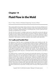
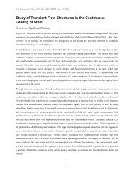
The Importance of Computational Models for Further Improvements of<br />
the <strong>Continuous</strong> <strong>Casting</strong> Process<br />
BRIAN G. THOMAS<br />
UNIVERSITY OF ILLINOIS Mechanical Engineering,<br />
Urbana, IL USA, 61801<br />
INTRODUCTION<br />
<strong>Continuous</strong> casting technology has advanced due<br />
to innovations resulting from knowledge gained<br />
from several different tools. These include<br />
expensive plant trials, laboaroray experiments,<br />
water models, and mathematical models. As the<br />
process becomes increasingly optimized and<br />
mature, simple trial and error is less likely to lead<br />
to success. At the same time, these trials become<br />
more costly, as more statistics must be gathered<br />
to quantify success. It is therefore important to<br />
have a correct understanding of the fundamental<br />
phenomena that occur in the process. Ideas<br />
which grow from deep understanding are more<br />
likely to lead to the successful trials and<br />
technology advances of the future.<br />
Computational modeling is likely to play an<br />
increased role in generating this understanding in<br />
the future, as advances in both computer<br />
hardware and software are making the modeling<br />
tools more powerful.<br />
Modeling has played a key role in many previous<br />
advances, which often involved relatively simple<br />
calculations. Examples include: unidirectional<br />
shell solidification models to design the<br />
containment length for a specified maximum<br />
casting speed; beam bending analysis to design<br />
support roll spacings to reduce bulging and<br />
internal cracks; thermal analysis to optimize water<br />
slot geometry to control mold hot face<br />
temperature, and shell shrinkage analysis to<br />
design parabolic tapers for billet molds. Modeling<br />
pioneers who contributed to continuous casting<br />
understanding include Brimacombe,<br />
Samarasekera, Schwerdtfeger, Wunnenberg,<br />
Fredriksson, Emi, Ohnaka and many others.<br />
This paper will present a few examples of<br />
computational models and the practical insights<br />
obtained from them. Due to space limitations,<br />
these examples will be taken only from work at<br />
the University of Illinois, although it is recognized<br />
that multitudes of other examples can be found<br />
elsewhere.<br />
IMPLEMENTATION OF PROCESS<br />
MODELS<br />
Models can be implemented to bring about<br />
tangible process improvements in several<br />
different ways, which are illustrated schematically<br />
in Fig. 1 [1] . Rooted in the fundamental laws of<br />
nature, numerical methods, and material property<br />
data, detailed simulations can improve basic<br />
understanding of the process. “Literature models“<br />
models are run only by the developer, so the<br />
understanding is communicated to process<br />
engineers through published results. New ideas<br />
may follow the increased understanding, which<br />
eventually may lead to process innovations.<br />
Alternatively, the engineer can run offline models<br />
to quantify and test hypotheses. In addition to<br />
generating confidence that an idea might work,<br />
these models can demonstrate the infeasibility of<br />
faulty ideas without expensive trials. Good ideas<br />
can be refined using offline models and optimized<br />
to select trial conditions. These models rely on<br />
careful lab experiments, physical models, and the<br />
results from plant trials in order to be accurate.<br />
The process understanding at the center of this<br />
paradigm comes from many different sources,<br />
including modeling. The process engineer is<br />
sometimes temped to short circuit process<br />
understanding and rely solely on the results of<br />
plant trials to design trials to improve the process.<br />
This is the mode often used in “fire fighting“ costly<br />
process problems. Although often successful in<br />
the short term, solutions achieved in this way can<br />
recur later. In addition, this trial and error<br />
approach requires many expensive trials.<br />
CCC 2000 IX<br />
Voest Alpine Conference on <strong>Continuous</strong> <strong>Casting</strong>, Linz, Austria, June 5-7, 2000
control<br />
numerical<br />
methods<br />
computer software<br />
packages<br />
PLANT<br />
Process Product<br />
online<br />
models<br />
sensor<br />
measurements<br />
Process understanding<br />
offline and<br />
literature<br />
models<br />
model<br />
calibration<br />
fundamental laws<br />
governing natural<br />
phenomena<br />
Results from<br />
Plant Trials<br />
experimental design<br />
model validation<br />
and improvement<br />
property data<br />
change operating<br />
practise / design<br />
process<br />
engineers<br />
lab experiments<br />
physical models<br />
Fig. 1: Implementation of process models [1]<br />
Ultimately, process understanding can be<br />
implemented into the process directly through<br />
online models. In the past, these models are<br />
often simple control algorithms, which rely heavily<br />
on feedback from sensors, such as mold level<br />
controllers. As computing power advances,<br />
online models are also advancing. Dynamic<br />
spray cooling models adjust water spray histories<br />
more accurately when based on true transient<br />
finite difference models of strand heat transfer.<br />
Knowledge regarding the mechanism of sticker<br />
breakout formation is quantified into sticker<br />
breakout detection systems to recognize the<br />
charactoristic temperature histories. Future online<br />
models will be used to process more<br />
thermocouple signals to detect other types of<br />
defects, perhaps using expert systems or other<br />
advanced algorithms. Before this is likely, the<br />
detailed understanding of how these defects form<br />
and relate to mold temperature histories must<br />
improve.<br />
FLOW SIMULATION<br />
Many important advances have been made to<br />
continuous casting metal delivery systems<br />
through the use of water models. Tundish flow<br />
control devices and nozzle design improvements<br />
2<br />
have come about through optimization based on<br />
the understanding obtained by visualizing the flow<br />
using these physical models. However, water<br />
models have difficulty in simulating multiphase<br />
flow (such as argon gas injection), due to the<br />
inherent differences between the physical<br />
properties of the steel / argon and water / air<br />
systems. Similar difficulties exist in the modeling<br />
of heat transfer in the liquid pool, solidification,<br />
and interactions between the liquid slag layer and<br />
the steel. These inaccuracies are one reason<br />
why extensive plant trials are still required to test<br />
new innovations in flow control devices.<br />
Mathematical models have the potential to<br />
overcome these difficulties. Unfortunately, the<br />
simulations are still so difficult that to date, they<br />
have generally been no more accurate than water<br />
models. Important phenomena such as vortexing<br />
and slag entrainment are still slightly beyond the<br />
capability of numerical simulation. With improving<br />
computational power, this will change in the<br />
future.<br />
The following subsections present examples of<br />
flow simulations applied to help optimize nozzle<br />
design, optimize argon injection, minimize<br />
transient flow, and optimize top surface powder<br />
layer behavior.<br />
Nozzle design optimization<br />
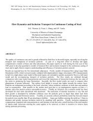
Past computational models of flow in nozzles<br />
have simulated steady state (time-averaged)<br />
velocity and pressure fields using turbulence<br />
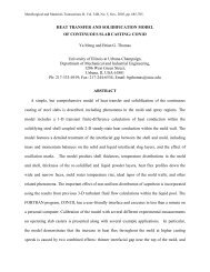
models such as K-ε [2-6] . Sample simulation<br />
results are shown in Fig. 2, which illustrates<br />
three-dimensional multiphase flow through a<br />
typical slide gate nozzle, for a 203 x 1320 mm<br />
slab cast at 1.0 m/min with 10SLPM Ar injection,<br />
50% gate opening, and 90° orientation of the slide<br />
gate. Note that the 90˚ orientation minimizes<br />
asymmetry between the two ports (B), but creates<br />
significant swirl flow in the jets (C). Previous<br />
simulations have shown that the 0˚ orientation<br />
generates significant asymmetry between the<br />
mass flow of the two jets entering the mold cavity,<br />
which causes detrimental bias flow in the mold<br />
and surface defects. Simulations predict that the<br />
45˚-orientation gate exhibits both types of<br />
asymmetry at almost the same level. Use of the<br />
latter two orientations has declined because of<br />
this.
(A)<br />
f l<br />
1.0<br />
0.5<br />
0.0<br />
1m/s<br />
(B) (C)<br />
Fig. 2: Simulated flow field for a typical<br />
nozzle (A) Liquid steel / argon gas fraction<br />
(B) Velocities in center plane parallel to WF<br />
(C) Velocities in center plane parallel to NF [7]<br />
Gas is observed to collect in the cavity of the slide<br />
gate, beneath the throttling plate, and at the top of<br />
the exit ports in Fig. 2 (A). These gas pockets<br />
encourage bubble coalescence, leading to<br />
occasional surges of gas and corresponding flow<br />
disruptions in the mold.<br />
The flow characteristics at nozzle outlet have<br />
been characterized for a wide range of nozzle<br />
geometries and casting conditions [7] .<br />
Proprietary design changes have been made to<br />
nozzle and port geometry at several different<br />
companies, based in part on the understanding<br />
gained from modeling results such as these.<br />
3<br />
Argon injection optimization<br />
The model results have been applied further to<br />
investigate the minimum argon gas flow rates<br />
needed to raise the internal pressure inside the<br />
nozzle to avoid air aspiration. This is one of the<br />
ways in which argon acts to reduce nozzle<br />
clogging. The pressure drop calculated over the<br />
nozzle can be related to the tundish level needed<br />
to drive the flow using Bernouli’s equation [6] .<br />
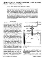
Fig. 3 shows that the pressure just below the<br />
throttling plate may drop below atmospheric<br />
pressure for some conditions. This can lead to air<br />
aspiration through the joints or walls (if the<br />
ceramic is porous). Model simulations have been<br />
applied to optimize argon injection to avoid this<br />
problem [6] .<br />
High<br />
Pressure<br />
Low<br />
Pressure<br />
o<br />
(a)<br />
z<br />
Distance from the point O at the center line (mm)<br />
x<br />
1000<br />
800<br />
600<br />
400<br />
200<br />
0<br />
o<br />
z<br />
FL=100%<br />
FL=70%<br />
60%<br />
50%<br />
FL=40%<br />
Gate opening FL<br />
Tundish level HT<br />
FL=40%, HT=1.545m<br />
FL=50%, HT=0.904m<br />
FL=60%, HT=0.653m<br />
FL=70%, HT=0.583m<br />
FL=100%, HT=0.513m<br />
Argon injection QG=10 SLPM<br />
<strong>Casting</strong> speed VC=1m/min<br />
Nozzle bore diameter DB=78mm<br />
x<br />
0 20 40 60 80 100<br />
(b) Pressure (KPa)<br />
Fig. 3: Pressure distribution in an SEN<br />
(a) Shaded contour plot at the center-plane<br />
(b) Pressure profile along the centerline [6]<br />
The particular nozzle investigated features argon<br />
injection into the lower portion of the upper<br />
tundish nozzle (UTN) just above the slide opening<br />
through a porous refractory wall chosen to<br />
produce uniform 1-mm bubbles. It had a 241 mm<br />
long upper tundish nozzle, 748 mm long SEN,<br />
with 78 mm bore diameter and 78 mm x 78 mm<br />
15˚down ports.<br />
Fig. 4 illustrates that increasing argon flow rate is<br />
indeed beneficial in being able to increase the<br />
minimum pressure in the nozzle. It is interesting<br />
to note, however, that part of this benefit arises<br />
simply due to the increase in slide gate opening<br />
required to accommodate the increased total
Lowest pressure in nozzle PL (KPa)<br />
volumetric flow. Increasing the gate opening also<br />
tends to reduce the pressure drop (for a given<br />
flow rate).<br />
15<br />
10<br />
5<br />
0<br />
-5<br />
-10<br />
Gate opening FL(%)<br />
52 54 56 58 60 70 FL@HT=0.6m<br />
48<br />
50<br />
52 FL@HT=0.8m<br />
44 46<br />
48 FL@HT=1.0m<br />
40<br />
42<br />
44 FL@HT=1.2m<br />
38<br />
40<br />
42 FL@HT=1.4m<br />
34<br />
36<br />
38<br />
FL@HT=1.6m<br />
<strong>Casting</strong> speed Vc =1m/min<br />
Nozzle bore diameter DB=78mm<br />
Tundish bath depth: HT<br />
HT=1.0m<br />
HT=1.6m<br />
HT=0.6m<br />
HT=0.8m<br />
HT=1.2m<br />
HT=1.4m<br />
-15<br />
0 2 4 6 8 10<br />
QG(SLPM)<br />
2 4 6 8 10 12 14 fAr(%,hot)<br />
1 2<br />
3 fAr(%,cold)<br />
Argon injection flow rate (QG) and volume fraction (fAr)<br />
Fig. 4: Effect of argon injection flow on<br />
raising minimum pressure in the SEN for<br />
constant tundish depth and casting speed [6]<br />
The results from many simulations of this nozzle<br />
using different slide gate openings, casting<br />
speeds, and argon gas levels were compiled<br />
together to determine the minimum argon flow<br />
rate required to just avoid negative pressure. Fig.<br />
5 shows the results.<br />
Less argon is needed if the nozzle bore size is<br />
chosen to avoid intermediate casting speeds so<br />
that the gate is either nearly fully open or is less<br />
than 50%. With increasing tundish depth, more<br />
argon is needed. Specifically, for high casting<br />
speeds, a 0.2m increase in tundish bath depth<br />
typically will require an additional 5 SLPM of<br />
argon to compensate the vacuum effect. For<br />
deep tundishes, popular for avoiding inclusion<br />
entrainment and carryover, it is infeasible for<br />
argon to avoid the vacuum effect.<br />
During slowdowns, the percent argon gas fraction<br />
increases while the tundish head and casting<br />
speed both decrease, which reduces the<br />
aspiration tendancy. Other modeling has shown<br />
the dangers of excessive argon gas in terms of<br />
radical changes to the fluid flow pattern in the<br />
mold cavity. Consequently, the argon gas flow<br />
rate used in several different plants has been<br />
decreased – both during steady casting, and<br />
4<br />
particularly during slow-downs in operation.<br />
Some of the specific predictions for this particular<br />
nozzle have been validated with plant<br />
measurements [6] . and further implementation of<br />
these results is proceeding.<br />
Minimum argon flow rate (SLPM) required<br />
for positive lowest pressure in nozzle<br />
40<br />
35<br />
30<br />
25<br />
20<br />
Nozzle bore diameter D =78mm<br />
B<br />
Tundish bath depth: H<br />
T<br />
H T =1.6m<br />
H T =1.4m<br />
H T =1.2m<br />
15<br />
10<br />
H =1.0m<br />
T<br />
5<br />
0<br />
H =0.6m<br />
T<br />
H =0.8m<br />
T<br />
00.5 1 1.5 2 2.5<br />
<strong>Casting</strong> speed V C (m/min, for 8"x52" slab)<br />
Fig. 5: Effect of casting speed and tundish<br />
depth on minimum argon flow rate required<br />
for positive pressure in nozzle [6]<br />
Minimizing mold flow transients<br />
Water models have traditionally been used to<br />
study complex flow phenomena in the mold.<br />
Computational models can help to understand the<br />
time-averaged flow patterns for steady casting<br />
conditions [8, 9] , particularly when phenomena<br />
such as electromagnetic forces, heat, and mass<br />
transfer are of interest.<br />
Recently, computational flow models have begun<br />
to be applied to shed light on transient<br />
phenomena, which are responsible for many of<br />
the important quality problems that arise during<br />
continuous casting [10, 11] . Fig. 6 shows sample<br />
results of instantaneous velocity vectors<br />
calculated at the center plane of a slab caster<br />
using a 3-D direct numerical simulation (left)<br />
compared with measurements obtained using<br />
particle image velocimetry in a water model<br />
(right). Several hundred such frames were<br />
averaged to produce the time mean flow pattern,<br />
which consists of smooth flow loops both and<br />
below the jet. The differences between the time<br />
average and instantaneous flow patterns are quite<br />
striking, however. Intermittent flow structures<br />
often break away from the main flow. Such a<br />
structure is seen cutting across the lower<br />
recirculation zone in Fig. 6, greatly affecting<br />
particle transport in that region. Along the top<br />
surface, these transients create level fluctuations<br />
and temporary velocity increases that could<br />
entrain flux and cause other quality problems.
Although much of this complexity is due to the<br />
turbulent nature of the flow, the condition of the jet<br />
streaming from the nozzle is very influential also.<br />
Some nozzle designs lead to more surface<br />
turbulence than others do, for a given set of<br />
casting conditions.<br />
Fig. 6: Instantaneous velocity vector field in<br />
strand centerplane: simulated (left) and<br />
measured (right) [10]<br />
It should be pointed out that computing power is<br />
still a major limitation of these transient<br />
calculations, as a month of supercomputer time<br />
was required for this two-minute simulation.<br />
Faster computers and algorithms will make this<br />
type of calculation increasingly popular in the<br />
future.<br />
Top surface powder layer optimization<br />
Understanding the behavior of the top surface flux<br />
layers is important to designing mold powders to<br />
ensure adequate flux feeding, and to avoid flux<br />
entrainment. Computational models are an<br />
important aid to plant experiments because the<br />
flow and thermal properties of flux and steel<br />
cannot be properly matched with water models.<br />
An example 3-D computational simulation was<br />
performed for a typical double roll flow pattern for<br />
1 m/min casting of a 230 x 1400 mm slab without<br />
gas through a 265 mm submerged bifurcated<br />
5<br />
nozzle with 15˚-down, 60 mm wide x 90 mm high<br />
rectangular ports [12] . The resulting interface<br />
profiles, shown in Fig. 7, reveal that the model is<br />
capable of matching plant measurements using<br />
nail board experiments [12] . The flux layer is<br />
dangerously thin near the narrow faces for these<br />
conditions, owing to both the raised contour of the<br />
steel and the shearing force from flow of steel<br />
towards the SEN.<br />
Distance below Top Surface of Powder - mm<br />
0<br />
-5<br />
-10<br />
-15<br />
-20<br />
-25<br />
-30<br />
-35<br />
POWDER FLUX<br />
STEEL<br />
Section taken 80 mm from wideface<br />
wall (parallel to wideface)<br />
Steel / FLux Interface (Measured)<br />
Flux / Melt Interface (Measured)<br />
Flux Melt Interface (3D Model)<br />
LIQUID FLUX<br />
0 100 200 300 400 500 600 700<br />
Distance from Narrow Face - mm<br />
Fig. 7: Simulated and measured powder /<br />
liqiud flux interface showing thinner liquid flux<br />
layer near narrow face due to double-roll flow<br />
pattern [12]<br />
The computational model can be further applied<br />
to investigate the effects of various practices on<br />
the behavior. For example, the results in Fig. 8<br />
show that intermittent powder addition leads to<br />
increased surface heat losses and thermal<br />
transients, which make the liquid flux layer thinner<br />
and variable over time. The increasing use of<br />
automated flux feeders may help to keep the<br />
powder depth constant, leading to steady and<br />
deeper liquid flux layers.<br />
FLUX THICKNESS (cm)<br />
~ 6.5<br />
~ 4.0<br />
~ 1.2<br />
Typical Measured<br />
Values at Center-plane<br />
and Quarter Mold Width<br />
Intermittent Powder Addition<br />
1.2<br />
1.1<br />
1.0<br />
0 30 60 120 240 360<br />
~ 120 s<br />
Constant Powder<br />
Flux Depth<br />
POWDER<br />
LIQUID<br />
Predicted 1-D Steady<br />
State Liquid Thickness<br />
≈ 2.1 cm<br />
TIME (s)<br />
Fig. 8: Variation in liquid layer thickness<br />
caused by intermittent powder addition [12]
GRADE TRANSITION OPTIMIZATION<br />
During sequence casting of different grades,<br />
composition variations arise in the product due to<br />
intermixing in the mold and in the strand. Models<br />
have been developed, validated, and calibrated to<br />
predict these composition differences, which exist<br />
both along the length and through the thickness of<br />
the slabs [13-15] . Many simulations under<br />
different conditions have revealed ways to change<br />
the casting conditions in order to minimize the<br />
intermediate region of the slab that must be<br />
downgraded [15] . The optimal solution depends<br />
on the cost of alternatives, such as flying tundish<br />
changes, grade separators and strand stoppages,<br />
the existance of a downgrade market, and the<br />
severity of the transition.<br />
Example 3-D simulation results for composition<br />
evolution in a 220 x 1320 mm strand are shown in<br />
Fig. 9 for a flying tundish change. New grade<br />
(composition = 1) is seen to penetrate into the old<br />
grade deep in the strand (composition = 0) faster<br />
than the casting speed, leading to centerline<br />
contamination of the old grade. This can be<br />
reduced with grade separators, thinner strands,<br />
lower casting speed (which reduces turbulence)<br />
and other changes. In addition, old grade persists<br />
in the mold and upper strand, leading to surface<br />
contamination of the new grade.<br />
Inlet<br />
(Nozzle<br />
Port) 0<br />
Mold<br />
Exit<br />
Distance below Meniscus (m)<br />
0.5<br />
1.0<br />
1.5<br />
2.0<br />
2.5<br />
3.0<br />
3.5<br />
4.0<br />
4.5<br />
5.0<br />
5.5<br />
6.0<br />
0.05<br />
0.1<br />
0.35<br />
0.2<br />
0.2<br />
0.1<br />
0.05<br />
0.02<br />
Centerline<br />
0.1<br />
0.65<br />
0.1<br />
0.05<br />
0.2<br />
0.02<br />
0.5<br />
0.35<br />
t=30 s t=120 s<br />
0.9<br />
0.65<br />
0.8<br />
0.65<br />
0.2<br />
0.1<br />
0.65<br />
0.5<br />
0.35<br />
0.95<br />
0.98<br />
0.95<br />
0.8<br />
0.65<br />
0.9<br />
t=300 s t=480 s<br />
Fig. 9: Evolution of relative concentration in<br />
strand after a flying tundish change with no<br />
grade separator [13]<br />
6<br />
Sample predictions of the composition variations<br />
produced in the final slab are shown in Fig. 10.<br />
This simulation is for a 10.2 tonne tundish refilled<br />
from 4.1 tonnes in 90s feeding into a 200 x 1320<br />
mm slab cast at 1.13 m/min. The results reveal<br />
the great differences between surface and center<br />
that can arise in a small tundish / thick slab<br />
operation. This has been confirmed by<br />
measurements of drilling samples, which match<br />
very closely with the predictions.<br />
Dimensionless Composition<br />
1<br />
0.8<br />
0.6<br />
0.4<br />
Cnew > 0.6<br />
7.4 m (22.3 tonnes)<br />
Centerline<br />
Surface<br />
Average<br />
0.2<br />
Col d < 0.1<br />
0<br />
-12 -10-8 -6 -4 -2 0 2 4 6<br />
Old Grade Distance up Slab (m) New Grade<br />
Fig. 10 a): 10 / 60 (stringent - lenient) grade<br />
transition [15]<br />
Dimensionless Composition<br />
1<br />
0.8<br />
0.6<br />
0.4<br />
0.2<br />
Cnew > 0.9<br />
Col d < 0.4<br />
Surface<br />
Average<br />
Centerline<br />
6.9 m (20.8 tonnes)<br />
0<br />
-12 -10-8 -6 -4 -2 0 2 4 6<br />
Old Grade Distance up Slab (m) New Grade<br />
Fig. 10 b): 40 / 90 (lenient - stringent) grade<br />
transition [15]<br />
Fig. 10. Relative composition variation within<br />
strand showing intermixed region for a small<br />
tundish operation<br />
The length and position of the intermixed slab<br />
which must be downgraded changes with many<br />
conditions. A comparison of Fig. 10 a) and b)<br />
shows that even with the same casting conditions<br />
(leading to the same composition profile), the<br />
order in which two different grades are cast can<br />
make a difference. In this case, casting the grade<br />
with the more stringent composition restrictions<br />
before the lenient grade shifts the intermixed
egion more than 2m downstream. Although the<br />
downgraded length increases slightly for this<br />
small tundish operation, this procedure would<br />
greatly reduce the intermixed length if the tundish<br />
were large or the strand were thin.<br />
Fast computational models that can accurately<br />
predict and quantify effects such as these have<br />
been developed [14] . These models are in use at<br />
several steel plants, where they are being applied<br />
to help with scheduling, optimizing casting<br />
conditions during the transition, identifying the<br />
slabs or slab portions that need to downgraded,<br />
and warning the customer about expected<br />
composition variations.<br />
MOLD TAPER DESIGN<br />
Compuational modeling is a natural tool for<br />
optimizing mold taper design. The governing<br />
phenomena are thermal contraction of the<br />
solidifying and cooling steel shell, which must be<br />
matched by the taper of mold walls, while taking<br />
into account the effects of mold distortion and<br />
variable thickness of the flux layer in the gap. The<br />
thermal contraction in turn is governed by the heat<br />
transfer from the shell, which depends on the<br />
steel grade and is complicated by phase<br />
transformations and strains due to elastic and<br />
viscoplastic creep deformation.<br />
Fig. 11: Calculated<br />
mold temperatures in<br />
round caster [16]<br />
7<br />
Modeling work has shown that the strand shrinks<br />
more near the top of the mold. Thus, a linear<br />
taper is inadequate for rigid mold-mold<br />
operations, such as round and square billet<br />
casting, where mold distortion is in the opposite<br />
direction. Parabolic or multiple taper profiles are<br />
needed and are now in common use.<br />
For example, taper has been optimized at Ilva-<br />
Dalmine round bloom caster based on the<br />
predictions of computational models that were<br />
calibrated with temperature measurements from<br />
mold thermocouples. [16] . Sample predictions<br />
are shown in Figs. 11 and 12, for temperature<br />
and ideal taper of the mold respectively during<br />
simulated casting of a 280 mm diameter round<br />
billet with C162 flux.<br />
In general, higher casting speed produces a<br />
hotter shell, so less taper is required, as shown in<br />
Fig. 12. However, the calculations also reveal<br />
that the flux layer thickness changes with casting<br />
speed and partly compensates for the change in<br />
the strand shrinkage. Thus, the change in taper<br />
with speed is much less than might be expected.<br />
In slab casting, the narrow face mold wall bends<br />
towards the shell, partly compensating for the<br />
nonlinear shell shrinkage. Thus, a simple linear<br />
taper is not far from optimal for many conventional<br />
slab casting operations [17] . Along the wide face,<br />
the shell is held against the mold wall by<br />
ferrostatic pressure, so not much taper is needed.<br />
Fig. 12: Effect of casting speed on ideal triple-taper predicted for a<br />
round billet mold [16]
The future challenge of high speed casting of thin<br />
slabs and billets using mold flux will benefit from<br />
the application of models such as these to<br />
optimize mold taper for the new conditions.<br />
THERMAL STRESS ANAYLSIS FOR<br />
UNDERSTANDING DEFECT FORMATION<br />
Computational modeling has often been used to<br />
investigate possible mechanisms for the formation<br />
of defects such as cracks. Even simple 1-D<br />
solidification models have been used with great<br />
success for this purpose. For example, by<br />
comparing the shell thickness profile with the<br />
location of a hot tear, the distance down the<br />
caster where a misaligned roll inititiated a radial<br />
streak crack can be identified.<br />
With other defects involving multi-dimensional<br />
effects and more complex stress development,<br />
more advanced thermal stress analysis is<br />
required. For example, longitudinal shell tears<br />
near mold exit involve thermal stresses, twodimensional<br />
corner effects, gaps affected by mold<br />
taper, gap heat transfer phenomena, and<br />
superheat delivered to the solidifying shell from<br />
the impinging flowing liquid jet. Models to<br />
investigate these phenomena have been applied<br />
to several different problems [18] .<br />
One example problem is breakouts at the offcorner<br />
narrow face when mold taper is insufficient<br />
and superheat is too high. An example of the<br />
predicted temperature contours and distorted<br />
shape of a transverse region near the corner is<br />
compared in Fig. 13 with measurements of a<br />
breakout shell from an operating steel caster. As<br />
expected, good agreement is obtained in the<br />
region of good contact along the wideface, where<br />
calibration was done. Near the corner along the<br />
narrow face, steel shrinkage is seen to exceed the<br />
mold taper. Thus, an air gap is predicted, which<br />
lowers heat extraction from the shell in the offcorner<br />
region of the narrow face. When combined<br />
with high superheat delivery from the bifurcated<br />
nozzle directed at this location, shell growth is<br />
greatly reduced locally. Just below the mold, this<br />
thin region along the off-corner narrow-face shell<br />
caused the breakout. Near the center of the<br />
narrow face, creep of the shell under ferrostatic<br />
pressure from the liquid is seen to maintain<br />
8<br />
contact with the mold, so much less thinning is<br />
observed. This illustrates the tremendous effect<br />
that superheat has on slowing shell growth, if<br />
there is a problem which lowers heat flow.<br />
Fig. 13: Uneven shell solidification in corner of<br />
slab caster at mold exit caused by inadequate<br />
narrow face taper [19]<br />
The modeling results, Fig. 14, show that lowering<br />
superheat helps to minimize the danger of this<br />
type of breakout. However, the results also show<br />
that improving the narrow face taper is a much<br />
better solution. Installing profilometers to<br />
continuously monitor and adjust taper during taper<br />
has been implemented in several casters. In<br />
addition, during widening width changes, taper<br />
should be increased according to [19] :<br />
∆W = taprn W L + Vw L / Vc<br />
where:<br />
∆W = difference in mold width at top and bottom<br />
of mold<br />
tapr<br />
n<br />
= optimal taper at steady width (%/m),<br />
Vw = speed of narrow face movement during<br />
width change<br />
Vc = casting speed<br />
W = mold width<br />
L = mold length<br />
Simulations such as these are needed to<br />
understand and help find solutions for new<br />
defects, such as those affecting thin slab and thin<br />
strip casting.<br />
CCC 2000 IX<br />
Voest Alpine Conference on <strong>Continuous</strong> <strong>Casting</strong>, Linz, Austria, June 5-7, 2000
Fig. 14: Increase in shell growth along offcorner<br />
of narrow face with increased taper and<br />
decreased superheat [20]<br />
CONCLUSIONS<br />
As increasing computational power continues to<br />
advance the capabilities of numerical simulation<br />
tools, modeling should play an increasing role in<br />
future advances to high-technology processes<br />
such as the continuous casting of steel. Modeling<br />
can augment traditional research methods in<br />
generating and quantifying the understanding<br />
needed to improve the process. Selected<br />
examples of increased understanding that have<br />
accompanied modeling at the University of Illinois<br />
are presented in the fields of multiphase fluid flow<br />
in the nozzle, mold cavity, and powder layers,<br />
grade transitions, and thermal stress analysis<br />
applied to mold taper, and off-corner breakouts in<br />
slabs. This understanding has lead to practical<br />
improvements to the operation and product.<br />
Areas where advanced computational modeling<br />
should play a crucial role in future improvements<br />
include transient flow simulation, mold flux<br />
behavior, taper design, and online quality<br />
prediction, especially for new problems and<br />
processes such as high speed bilet casting, thin<br />
slab casting, and strip casting.<br />
OUTLOOK<br />
Future advances to the continuous casting<br />
process will not come from either models,<br />
experiments, or plant trials. They will come from<br />
ideas generated by people who understand the<br />
process and the problems. This understanding is<br />
rooted in knowledge, which can be confirmed,<br />
deepened, and quantified by tools which include<br />
computational models. As our computational<br />
tools continue to improve, they should grow in<br />
importance in fulfilling this important role, leading<br />
to future process advances.<br />
9<br />
ACKNOWLEDGEMENTS<br />
This work was supported by the <strong>Continuous</strong><br />
<strong>Casting</strong> <strong>Consortium</strong> at UIUC, (AK Steel,<br />
Allegheny Ludlum, Columbus Stainless, Ispat-<br />
Inland Steel, LTV, and Stollberg, Inc.) and the<br />
National Science Foundation (Grant DMI-98-<br />
00274). The author also wishes to thank the<br />
current and former graduate students and industry<br />
colleagues for their research contributions which<br />
are described here and the National Center for<br />
Supercomputing Applications at UIUC for<br />
computing time and use of commercial software.<br />
REFERENCES<br />
1. B. Thomas and J.K. Brimacombe:<br />
"Process Modeling, Chap. 8", in<br />
Advanced Physical Chemistry in Process<br />
Metallurgy, N. Sano, W. Lu and P.<br />
Riboud, eds., Academic Press, London,<br />
UK, 1997, pp. 253-279.<br />
2. L.M. Mika, B.G. Thomas and F. Najjar:<br />
"Simulation of Fluid Flow Inside a<br />
<strong>Continuous</strong> Slab <strong>Casting</strong> Machine",<br />
Metallurgical Transactions B, 1990, vol.<br />
21B, pp. 387-400.<br />
3. D.E. Hershey, B.G. Thomas and F.M.<br />
Najjar: "Turbulent Flow through<br />
Bifurcated Nozzles", International Journal<br />
for Numerical Methods in Fluids, 1993,<br />
vol. 17, pp. 23-47.<br />
4. F.M. Najjar, B.G. Thomas and D.E.<br />
Hershey: "Turbulent Flow Simulations in<br />
Bifurcated Nozzles: Effects of Design<br />
and <strong>Casting</strong> Operation", Metallurgical<br />
Transactions B, 1995, vol. 26B (4), pp.<br />
749-765.<br />
5. H. Bai and B.G. Thomas: "Two-phase<br />
flow in tundish nozzles during continuous<br />
casting of steel slabs", Materials<br />
Processing in the Computer Age III, V.<br />
Voller and H. Henein, eds., Nashville,<br />
TN, TMS, Warrendale, PA, 2000, pp.<br />
85-99.
6. H. Bai and B.G. Thomas: "Effect of<br />
Clogging, Argon Injection and <strong>Casting</strong><br />
Conditions on Flow Rate and Air<br />
Aspiration in Submerged Entry Nozzles",<br />
in Steelmaking Conference Proceedings,<br />
vol. 83, TMS, Warrendale, PA,<br />
Pittsburgh, PA, 2000, pp. 183-197.<br />
7. H. Bai: Argon Bubble Behavior in Slide-<br />
Gate Tundish Nozzles During<br />
<strong>Continuous</strong> <strong>Casting</strong> of Steel Slabs, PhD<br />
Thesis, University of Illinois, 2000.<br />
8. X. Huang, B.G. Thomas and F.M. Najjar:<br />
"Modeling Superheat Removal during<br />
<strong>Continuous</strong> <strong>Casting</strong> of Steel Slabs",<br />
Metallurgical Transactions B, 1992, vol.<br />
23B (6), pp. 339-356.<br />
9. B.G. Thomas, X. Huang and R.C.<br />
Sussman: "Simulation of Argon Gas Flow<br />
Effects in a <strong>Continuous</strong> Slab Caster",<br />
Metall. Trans. B, 1994, vol. 25B (4), pp.<br />
527-547.<br />
10. S. Sivaramakrishnan, H. Bai, B.G.<br />
Thomas, P. Vanka, P. Dauby and M.<br />
Assar: "Transient Flow Structures in<br />
<strong>Continuous</strong> Cast Steel", in Ironmaking<br />
Conference Proceedings, vol. 59, ISS,<br />
Warrendale, PA, Pittsburgh, PA, 2000,<br />
pp. 541-557.<br />
11. S. Sivaramakrishnan, B.G. Thomas and<br />
P. Vanka: "Transient Flow Structures in<br />
<strong>Continuous</strong> Cast Steel", in Materials<br />
Processing in the Computer Age, V.<br />
Voller and H. Henein, eds., TMS,<br />
Warrendale, PA, Nashville, TN, 2000, pp.<br />
189-198.<br />
12. R. McDavid and B.G. Thomas: "Flow and<br />
Thermal Behavior of the Top-Surface<br />
Flux/ Powder Layers in <strong>Continuous</strong><br />
<strong>Casting</strong> Molds", Metallurgical<br />
Transactions B, 1996, vol. 27B (4), pp.<br />
672-685.<br />
13. X. Huang and B.G. Thomas: "Modeling<br />
of Steel Grade Transition in <strong>Continuous</strong><br />
Slab <strong>Casting</strong> Processes", Metallurgical<br />
Transactions, 1993, vol. 24B, pp. 379-<br />
393.<br />
10<br />
14. X. Huang and B.G. Thomas: "Intermixing<br />
Model of <strong>Continuous</strong> <strong>Casting</strong> During a<br />
Grade Transition", Metallurgical<br />
Transactions B, 1996, vol. 27B (4), pp.<br />
617-632.<br />
15. B.G. Thomas: "Modeling Study of<br />
Intermixing in Tundish and Strand during<br />
a <strong>Continuous</strong>-<strong>Casting</strong> Grade Transition",<br />
ISS Transactions, 1997, vol. 24 (12), pp.<br />
83-96.<br />
16. M.R. Ridolfi, B.G. Thomas, G. Li and<br />
U.D. Foglia: "The optimization of mold<br />
taper for the Ilva-Dalmine round bloom<br />
caster", Rev. Met., 1994, vol. 91, pp.<br />
609-620.<br />
17. B.G. Thomas, G. Li, A. Moitra and D.<br />
Habing: "Analysis of Thermal and<br />
Mechanical Behavior of Copper Molds<br />
during <strong>Continuous</strong> <strong>Casting</strong> of Steel<br />
Slabs", Iron and Steelmaker (ISS<br />
Transactions), 1998, vol. 25 (10), pp.<br />
125-143.<br />
18. B.G. Thomas, A. Moitra and R. McDavid:<br />
"Simulation of Longitudinal Off-Corner<br />
Depressions in <strong>Continuous</strong>ly-Cast Steel<br />
Slabs", ISS Transactions, 1996, vol. 23<br />
(4), pp. 57-70.<br />
19. A. Moitra and B.G. Thomas: "Application<br />
of a Thermo-Mechanical Finite Element<br />
Model of Steel Shell Behavior in the<br />
<strong>Continuous</strong> Slab <strong>Casting</strong> Mold", in<br />
Steelmaking Proceedings, vol. 76, Iron<br />
and Steel Society, Dallas, TX, 1993, pp.<br />
657-667.<br />
20. G.D. Lawson, S.C. Sander, W.H. Emling,<br />
A. Moitra and B.G. Thomas: "Prevention<br />
of Shell Thinning Breakouts Associated<br />
with Widening Width Changes", in<br />
Steelmaking Conference Proceedings,<br />
vol. 77, Iron and Steel Society,<br />
Warrendale, PA, 1994, pp. 329-336.