full Findings text PDF - Continuous Casting Consortium - University ...
full Findings text PDF - Continuous Casting Consortium - University ...
full Findings text PDF - Continuous Casting Consortium - University ...

You also want an ePaper? Increase the reach of your titles
YUMPU automatically turns print PDFs into web optimized ePapers that Google loves.
B.G. Thomas, Final Report NSF Grant DMI-98-00274, Jan. 31, 2002.<br />
Study of Transient Flow Structures in the <strong>Continuous</strong><br />
<strong>Casting</strong> of Steel<br />
Overview of Significant <strong>Findings</strong><br />
As part of a long-term effort to develop and apply comprehensive models of continuous casting of steel, this report<br />
summarizes the many different findings obtained under NSF Grant DMI-98-00274 from 1998 to 2001. After a brief<br />
overview of all findings, an introduction and background to this project are provided, followed by a detailed<br />
description of findings on each subproject.<br />
Several different computational models of turbulent fluid flow and heat transfer have been developed to simulate<br />
flow phenomena in the nozzle and mold regions of the continuous casting of steel slabs. The models have been<br />
calibrated, validated, and tested quantitatively through comparisons with water model experiments, steel plant trials,<br />
and metallographic measurements at LTV Steel and several other steel companies who are cosponsoring this<br />
research. Next, this work has revealed many specific insights into multiphase flow through nozzles, which are<br />
important to designing nozzle geometry to avoid clogging and flow-related problems in the mold, which may<br />
generate defects in the final steel product. Contributions in three different areas include: 1) characterizing flow<br />
conditions exiting a typical slide-gate nozzle as a function of casting conditions 2) developing a clogging index to<br />
reveal when clogging has occured and 3) providing guidelines to optimize argon injection to avoid clogging due to<br />
air aspiraction in the nozzle.<br />
Through extensive comparisons of steady and transient models, particle-image velocimetry measurements in water<br />
models, and plant measurements, all taken under similar conditions, this work has quantified how simple K-ε flow<br />
models can reasonably predict time-averaged multiphase flow of molten steel under the conditions of interest.<br />
Provided that the inlet conditions are accurate, large-eddy simulations of transient flow can further reveal important<br />
transient flow structures and accurately predict time-dependent signals, such as RMS velocity, at least for single<br />
phase flow. Further application of this model to inclusion transport has revealed its ability to match the distribution<br />
and flotation removal of inclusion particles in the transient flow field with water model measurements, both<br />
qualitatively and quantitatively. In addition to the inlet velocity and direction, the turbulence and swirl at the inlet<br />
ports has been shown to be very important to both the fluid flow and inclusion motion. Secondly, transient LES<br />
simulations of impinging jets are performed and applied to predict heat transfer to the surface. This is important for<br />
the prediction of shell thinning and breakouts. The angle of jet impingement against the narrow face also appears to<br />
have an important influence on the fraction of inclusion particles transported down deep into the caster, where they<br />
may become entrapped to form defects. Thirdly, steady, multiphase flow computations are compared with flow<br />
patterns observed in both a 0.4-scale water model and an operating steel caster with argon gas injection. For the<br />
same conditions, the water model and steel caster produced very different flow behavior. The computational model<br />
was able to match the measured flow patterns in both systems. The model is extended to predict the flow pattern as<br />
a function of operating conditions, which can be used as guidelines to optimize gas injection practice in the real<br />
process.<br />
1
B.G. Thomas, Final Report NSF Grant DMI-98-00274, Jan. 31, 2002.<br />
In addition to its contributions to the continuous casting of steel, this work has demonstrated the potential of<br />
computational flow modeling to match real industrial processes. Moreover, computational models are shown to be<br />
as accurate or better than water models, especially when complex related phenomena such as particle motion and<br />
multiphase flow are involved. The models will be further improved and applied in future parametric studies.<br />
1. INTRODUCTION<br />
Continued viability of the high-volume low-profit-margin steel industry depends upon improved efficiency and<br />
consistent steel quality, relative to low cost imports. Lowering defects from internal inclusions is one way to<br />
achieve this, while simultaneously improving steel minimum strength, fatigue life, surface appearance, yield and<br />
energy efficiency (from reduced rejects). Even a one percent reduction in yield loss would save about $100 million<br />
per year, (based on the roughly 100 million tons of steel produced each year the U.S. [1] and $100 per ton net cost of<br />
scrapping). Moreover, reliable lowering of inclusion entrapment could allow thinner gage products (with associated<br />
weight and energy savings) and could reduce the need for costly secondary refining steps, such as vacuum arc<br />
refining and electroslag remelting. Thus, there are tremendous economic, environmental and safety incentives for<br />
understanding how to lower the inclusion content of the steel.<br />
<strong>Continuous</strong> casting produces 96% of the steel manufactured in the U.S. [1] and is the last, and most important,<br />
processing step where quality can either be generated or removed. Plant observations have found that many serious<br />
quality problems are directly associated with the flow pattern in the mold. [2] Defects caused by nonoptimal fluid<br />
flow are even more important to the nearer-net-shape thin-slab casting processes, which are starting to transform the<br />
industry. [3] This is because higher velocities are required through a smaller inlet nozzle to cast a thin section slab<br />
with the same throughput. Thus, design and control of the fluid flow pattern in the continuous casting mold to<br />
minimize defects is of crucial importance to the steel industry.<br />
The flow pattern in the mold can be controlled by many variables, including the nozzle and mold geometry,<br />
submergence depth, steel flow rate, argon injection rate, electromagnetic stirring, and flux layer properties. Many of<br />
these parameters are easy and inexpensive to change and yet have a profound influence on flow and corresponding<br />
quality. Traditionally, flow pattern design is done through trial and error, based on qualitative experiments with<br />
water models, plant trials, and the plant operator’s experience with defects. Identifying an optimal flow pattern is<br />
very difficult, because the fundamental relationships between flow pattern and defects such as inclusion entrapment<br />
have not been quantified. Thus, each casting operation requires its own expensive experiments, and old defects<br />
often reappear when changes in the process occur. With so many different operations and new processes to<br />
optimize, the industry can no longer afford this approach.<br />
The flow in the mold region is highly turbulent, and is characterized by large-scale unsteadiness. A better<br />
understanding of the flow physics in this mold region is important to the understanding of defect formation, so that<br />
lasting improvements in process geometry and conditions can be found. Thus, this study was undertaken to apply<br />
computational models to increase understanding of flow and related phenomena in the region of the continuous<br />
casting mold, using both steady and transient models.<br />
2
B.G. Thomas, Final Report NSF Grant DMI-98-00274, Jan. 31, 2002.<br />
First, the reliability of the different models is demonstrated through extensive comparison with water models and<br />
measurements in operating steel casters. Next, steady simulations are conducted to characterize fluid flow through<br />
the nozzle as a function of nozzle geometry and casting conditions. With the help of fundamental studies of bubble<br />
formation, the nozzle model is further applied to optimize argon injection to suggest guidelines to avoid nozzle<br />
clogging. Fully transient models of flow in the caster using Large Eddy Simulation are developed using LES,<br />
evaluated, and applied to simulate flow in the mold. Then, the accuracy and relative advantages of the different<br />
models of fluid flow are compared with flow measurements in both water models and operating casters. Next, the<br />
models are applied to simulate associated phenomena of heat transfer, particle motion, and multiphase flow<br />
phenomena due to argon bubble injection. Guidelines are developed to predict optimal gas flow rates that should<br />
assist in designing better mold flow patterns to improve steel quality.<br />
The increased fundamental understanding of fluid flow phenomena resulting from this study should benefit the steel<br />
industry by leading to improvements in design and operating conditions that improve flow pattern in the continuous<br />
casting strand and lower costly defects. In addition, improved capabilities of flow models and increased<br />
understanding of flow model accuracy should benefit future models of flow in many other processes.<br />
2. THE PROCESS<br />
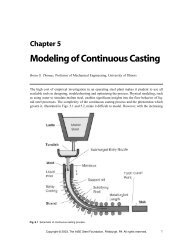
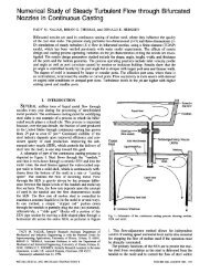
A schematic of part of the continuous casting process is depicted in Fig. 1. [4] Steel from the ladle flows through the<br />
“tundish,” and then it exits down through a ceramic Submerged Entry Nozzle (SEN) and into the mold. Here, the<br />
steel freezes against the water-cooled copper walls to form a thin solid shell, which is continuously withdrawn from<br />
the bottom of the mold at a “casting speed” that matches the flow of the incoming metal. Flow through the SEN is<br />
gravity driven by the pressure difference between the liquid levels of the tundish and the mold top free surfaces.<br />
The flow rate is controlled (using feedback from a level sensor) to maintain the liquid level in the mold as constant<br />
as possible. In one method, a “stopper rod” extends down through the tundish to partially plug the exit. In another<br />
method, a “slide gate” blocks off a portion of the SEN pipe section by moving a disk-shaped plate through a<br />
horizontal slit across the entire SEN. Such flow adjustment methods allow for independent control of casting speed<br />
and metal level, and are essential for stopping the flow of molten steel if the operation must be abruptly terminated.<br />
The submerged nozzle protects the molten steel from exposure to air, which helps to avoid reoxidation and inclusion<br />
formation. Together with the casting speed, mold geometry, argon gas injection rate, and other parameters, the<br />
nozzle geometry also controls the flow pattern created in the mold cavity. This flow pattern in turn controls the<br />
entrapment of inclusions and other defects which determine the steel quality.<br />
3. THE PROBLEM<br />
A number of costly defects in the cast steel can be directly related to the flow pattern in the mold, as shown in the<br />
schematic in Fig. 2. For example:<br />
a) The jets of molten steel exiting the nozzle carry inclusions into the mold cavity. If these inclusions join the lower<br />
recirculation zones, they can gradually spiral and become trapped in the solidifying front leading to internal cracks,<br />
slivers in the final rolled product, and blisters. [5] Previous work by the PI [6] suggests that transient flow structures,<br />
3
B.G. Thomas, Final Report NSF Grant DMI-98-00274, Jan. 31, 2002.<br />
similar to vortex shedding, may contribute to inclusion entrapment in the lower zone. The flow of molten steel can<br />
also generate harmful inclusions by shearing the top surface and entraining the liquid flux. [5]<br />
b) Transient surges in the steel jets leaving the nozzle parts may cause asymmetric flow, leading to sloshing or<br />
waves in the molten pool. [7] This results in sudden fluctuations in the level of the free surface, which disrupts initial<br />
solidification and entraps mold flux in the solidifying steel, leading to surface depressions and other defects in the<br />
final product. [8, 9] It has been shown [10] that such defects can be traced to the transient turbulence structures in the<br />
flow.<br />
c) The flow of the steel in the upper mold greatly influences the shape of the top free surface. If this level becomes<br />
too high, which is common near the narrow faces due to the upwelling flow there, liquid mold flux is unable to feed<br />
the gap between the shell and the mold. This leads to reduced heat flow, thinning of the steel, and longitudinal<br />
surface cracks. [11]<br />
d) Further, the flow of molten steel exiting the nozzle also carries superheat. If too much heat is delivered locally,<br />
[12, 13]<br />
where the shell is already thin, there is the possibility of a breakout, where liquid steel bursts from the shell.<br />
The problem is worse with higher flow rates and non-uniform flow from the nozzle.<br />
e) Finally, argon gas is frequently employed at several stages in the continuous casting process to encourage mixing,<br />
to help prevent nozzle clogging, and to promote the flotation of solid inclusion particles from the liquid steel. It<br />
usually enters the continuous casting mold after injection into the submerged entry nozzle and eventually escapes<br />
from the liquid steel surface through the mold flux powder layer. Argon gas also prevents nozzle clogging by<br />
creating turbulence that discourages adherence of inclusions to the nozzle walls. However, the argon gas<br />
significantly changes the flow pattern in the mold. The detrimental effects of argon include entrapment of the<br />
bubbles inside the solidified steel, creating voids that decrease the strength of the material. The trapped bubbles are<br />
often covered with small inclusions. During rolling, the inclusion clusters elongate to create long slivers in the final<br />
product. During subsequent annealing processes, the trapped bubbles expand to create surface blisters and “pencil<br />
pipes”. [5] These intermittent defects are particularly costly because they are often not detected until after many<br />
subsequent finishing steps. Thus, there is a great incentive to understand how to control the mold flow pattern in<br />
order to minimize particle entrapment and the associated quality problems.<br />
4. RESULTS<br />
<strong>Findings</strong> of this work are summarized in the following sections. Complete results and details are provided in the<br />
more than 30 publications resulting from this project to date [4, 14-44] and in the website http://ccc.me.uiuc.edu.<br />
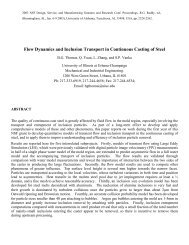
5. FLOW IN THE NOZZLE (Hua Bai)<br />
A. Model of multiphase flow through continuous casting nozzles<br />
The quality of continuous-cast steel is greatly affected by the flow pattern in the mold, which depends mainly on the<br />
jets flowing from the outlet ports in casting with submerged tundish nozzles. A three-dimensional Eulerian<br />
multiphase model using the finite-difference program CFX has been applied to study the steady turbulent flow of<br />
liquid steel with argon bubbles in slide-gate tundish nozzles. [30] Modeling procedures for obtaining quantitative<br />
4
B.G. Thomas, Final Report NSF Grant DMI-98-00274, Jan. 31, 2002.<br />
predictions have been identified. The model was subjected to rigorous grid refinement study, evaluation of<br />
convergence strategies, and comparison with experiments.<br />
Example results from the model are given in Fig. 3, which shows the gas distribution, and views of the 3D velocity<br />
profile within the nozzle. Gas is shown to collect preferentially just below the slide gate flow control device, and at<br />
the tops of the nozzle ports. Equations to quantify average jet properties at nozzle exit have been developed. Most<br />
of the gas exits the upper portion of the nozzle port while the main downward swirling flow contains very little gas.<br />
The injected gas temperature is calculated to be 99% of the steel temperature at the instant of injection, so gas heatup<br />
does not need to be considered in the future calculations. A weighted average scheme for the overall outflow is<br />
developed to quantify jet characteristics such as jet angle, jet speed, back flow zone fraction, turbulence and biased<br />
mass flow. It is also possible to characterize the outflow from each port as two split jets. These are an upward gasrich<br />
jet and a generally downward liquid-rich jet, which determines the overall jet properties. The model is used next<br />
to perform extensive parametric studies to investigate the effects of casting operation conditions and nozzle design.<br />
B. Water Model Experiments and Particle Image Velocimetry for Model Validation<br />
Particle Image Velocimetry (PIV) measurements, performed on a 0.4-scale water model, have revealed the detailed<br />
nature of the fluctuating swirling velocity profile exiting the nozzle. [30, 45] Predictions with the computational model<br />
agree reasonably with the time-averaged PIV measurements. An example is given in Fig. 4, which shows how the<br />
swirling flow produces generally upward velocities from one side of the nozzle, and downward flow from the other.<br />
The computational model captures both results, so is demonstrated to be suitable for simulating dispersed bubbly<br />
flows, which exist for a wide range of practical gas injection rates in the continuous casting of steel (and other<br />
processes).<br />
C. Nozzle model application: parametric studies<br />
The validated nozzle model has been applied to perform a large, systematic study of the effect of important<br />
operating parameters on flow exiting the nozzle. [28, 45] Specifically, the jet characteristics (direction, speed, spread,<br />
etc.) exiting the nozzle ports are quantified for different operating parameters (including nozzle bore diameter, slide<br />
gate orientation, slide gate opening fraction, injected fraction of argon gas, bubble size, port angle, and port shape).<br />
Argon gas injection bends the jet angle upward, enhances the turbulence level, and reduces the size of the back flow<br />
zone. Gas injection becomes less influential with increasing casting speed. The off-center blocking effect of the<br />
slide-gate generates asymmetric flow that changes with the gate orientation. The 0° gate orientation creates the<br />
worst biased flow between the two ports. The 90° orientation generates significant swirl and directs the jet slightly<br />
toward one of the wide faces. The 45° orientation generates both types of asymmetry, and thus appears undesirable.<br />
The horizontal jet angle indicates asymmetric flow in the horizontal plane. It increases with decreasing gate opening<br />
and decreasing gas injection, and ranges from 3°-5°. Most jet characteristics reach their maximum or minimum<br />
values near the critical opening of 60% (linear). Larger bubbles exert a greater influence on the flow pattern. The<br />
vertical jet angle becomes steeper with steeper port angle and more slender port shape.<br />
These results are a necessary first step in designing nozzles to understand, control, and optimize the important flow<br />
pattern in the mold. Flow conditions inside the nozzle are also important in their own right. As an example, Fig. 5<br />
shows the effect of slide gate opening fraction on the pressure drop inside the nozzle. [30] Of greatest significance is<br />
5
B.G. Thomas, Final Report NSF Grant DMI-98-00274, Jan. 31, 2002.<br />
the drop in pressure at the slide gate, which sometimes drops below one atmosphere (0 gauge). This condition can<br />
allow air to aspirate in through gaps in the refractory, if there are any leaks, which would cause reoxidation,<br />
clogging, and other quality problems. It has been quantified as a function of casting conditions. [28]<br />
D. Nozzle model application: nozzle clogging index<br />
The implications of the nozzle model results have been extended in a comprehensive review on how to avoid nozzle<br />
clogging, highlighting the potential contribution of computational modeling. [34] In particular, the model results are<br />
shown to be useful as a clogging index to detect when nozzle clogging is present, before harmful flow defects occur.<br />
Clogging of the tundish nozzle is a major castability problem in continuous casting of steel for several reasons.<br />
Firstly, clogging increases the frequency of operation disruptions to change nozzles or tundishes or even to stop<br />
casting. These extra transitions increase operating cost, decrease productivity, and lower quality. Secondly,<br />
clogging can lead directly to a variety of quality problems. Clogs change the nozzle flow pattern and jet<br />
characteristics exiting the ports, which can disrupt flow in the mold, leading to surface defects in the steel product<br />
and even breakouts. Dislodged clogs also disturb the flow and either become trapped in the steel or change the flux<br />
composition, leading to defects in either case. Quality problems also arise from the mold level transients which<br />
occur as the flow control device compensates for the clogging.<br />
Because the nature of steelmaking produces large volumes of liquid containing inclusions, which all channel<br />
through a restricted nozzle opening, tundish nozzle clogging is likely to remain a chronic problem of every<br />
continuous casting operation. Clogging problems can be solved by first identifying the cause, through analysis of<br />
the clog material. Solutions philosophies are based on minimizing inclusions by improved steelmaking practices,<br />
optimizing fluid flow and transfer processes, controlling steel alloy additions, slag and refractory compositions,<br />
improving nozzle material and design, and avoiding air aspiration. Air aspiration problems in the tundish nozzle can<br />
be detected by monitoring argon back pressure during casting and by checking for nitrogen pickup between the<br />
tundish and mold. Clogging and other quality problems are indicated by level fluctuations in the mold, which result<br />
from the changes in the nozzle pressure drop and jets exiting the ports.<br />
The extent of clogging can be inferred by comparing the measured steel flow rate with the theoretical value,<br />
predicted in this work for different nozzle geometry, tundish depth, gas flow rate and percent gate opening. Fig. 6<br />
shows the theoretical flow rate in a typical nozzle as a function of important conditions. Detecting clogging in this<br />
way is not easy because clogging initially increases flow (due to a potential streamlining effect), before it becomes<br />
great enough to restrict the flow channel. This variation in flow rate with clogging progression is shown in Fig. 7.<br />
Finally, the argon injection rate should be optimized to prevent air aspiration while fostering good mold flow. The<br />
conditions needed to maintain positive pressure in the nozzle were quantified next.<br />
E. Nozzle model application: argon gas flow optimization<br />
The validated multiphase flow model of the nozzle was applied to perform over 150 simulations, in order to<br />
optimize argon gas injection levels in the nozzle for a range of practical conditions (including nozzle clogging,<br />
argon injection, tundish bath depth, slide gate opening position and nozzle bore diameter). [45] Specifically, the<br />
model results were processed (using simple inverse models) to quantify the minimum argon gas injection levels<br />
needed to avoid negative pressure in the nozzle, and thereby avoid air aspiration and the accompanying reoxidation,<br />
6
B.G. Thomas, Final Report NSF Grant DMI-98-00274, Jan. 31, 2002.<br />
inclusion formation, and nozzle clogging. An example is shown in Fig. 8. [27]<br />
Increasing argon gas was found to<br />
generally increase nozzle pressure. This may help to reduce air aspiration by increasing the minimum pressure,<br />
which is found just below the slide gate. More argon is needed to avoid a partial vacuum effect at intermediate<br />
casting speeds and in deeper tundishes. Argon flow should be reduced during shallow tundish and low casting speed<br />
conditions (such as encountered during a ladle transition) in order to avoid detrimental effects on flow pattern.<br />
Argon should also be reduced at high casting speed, when the slide gate is open wider and the potential for air<br />
aspiration is less. The optimal argon flow rate depends on the casting speed, tundish level, and nozzle bore diameter<br />
and is quantified in this work for a typical nozzle and range of bore diameters and operating conditions. Some<br />
conditions (low tundish level and low casting speed) require very little gas to avoid detrimental air aspiration, while<br />
other conditions (deep tundish) required more argon than is practical. [27] These practical guidelines on how to<br />
optimize argon injection in the plant should lead to steel quality improvements.<br />
6. FLOW IN THE MOLD<br />
A. Improved models of flow in continuous casting molds (S. Sivaramakrishnan; Q. Yuan)<br />
Models to simulate both steady and transient flow in the continuous casting mold have produced many important<br />
findings. [40] Examples of the predicted time-averaged flow patterns in the centerplane of a water model of the<br />
continuous casting mold are given in Fig. 9, using the Large Eddy Simulation method (with two different inlet<br />
conditions) and the K-ε model. The LES simulations captured important transient flow structures and small time<br />
scales such as top surface velocity variations. The two LES computations captured the main transient features of the<br />
actual flow in the mold region, including the evolution of vortex structures in the upper roll and lower roll regions,<br />
and the “staircase shaped” jet flow pattern. The computed time scale for the “short-circuit” vortex evolution has the<br />
same order as the PIV measurements (7s-10s). At a sample point near the top surface, LES results captured the<br />
small time scale (0.7s) of the velocity variations measured using PIV. This suggests that these velocity fluctuations<br />
are caused by the turbulent nature of the flow, at least at this small time scale.<br />
The comparisons of fluid velocity along the jet, near the top surface and in the lower roll region proves that LES is<br />
capable of accurately predicting both the time-averaged velocity field and its turbulent variations. The secondary<br />
flow and turbulence present in the inlet flow are found to be influential on the jet speed and flow patterns and<br />
thereby the top surface velocity. This work shows that LES is capable of accurately predicting the turbulent<br />
information of the flow field in the mold region. It also shows that an accurately prescribed turbulent inlet flow field<br />
helps to better simulate the flow in the mold region, and suggests that the important top surface velocities can be<br />
controlled by controlling the inlet flow pattern.<br />
B. Plant Benchmark experiments for continuous casting model validation (D.Creech, S.<br />
Sivaramakrishnan, and Steel Industry Researchers M. Assar (LTV) and R. O’Malley (AK) )<br />
Experiments have been conducted to quantify fluid flow, superheat dissipation, solidifying steel shell growth, heat<br />
transfer and microstructure during the continuous casting of stainless-steel slabs at the AK Steel caster in Mansfield,<br />
OH. [46]<br />
These experimental measurements have further been applied to develop, calibrate, and validate<br />
mathematical models of both fluid flow and heat flow in continuous casting. [22] Three-dimensional turbulent flow<br />
of molten steel in the nozzle and the mold cavity is modeled with the finite difference code CFX 4.2, [47] using the<br />
7
B.G. Thomas, Final Report NSF Grant DMI-98-00274, Jan. 31, 2002.<br />
standard K-ε turbulence model and a fixed, structured grid. The results agree with flow measurements in a <strong>full</strong>-scale<br />
water model. The corresponding steady heat conduction equation is solved to predict the distribution of superheat in<br />
the molten pool. The predicted temperatures in the molten steel compare well with measurements conducted by<br />
inserting a thermocouple probe downward through the top surface at several locations in the operating thin slab<br />
caster. Next, solidification of the steel shell is simulated using a transient heat conduction model that features a<br />
detailed treatment of the flux layers in the interfacial gap and incorporates the superheat flux calculated from the<br />
fluid flow model. This model was calibrated with temperature measurements obtained from thermocouples in the<br />
copper mold during operation. It was run under the transient conditions present during a breakout. The predicted<br />
shell thickness profiles are compared with many shell thickness profiles measured around the perimeter of a<br />
breakout shell. Of greatest interest is the uneven thinning of the shell near the narrow face where the steel jet<br />
impinges, which is different between steady-state and the transient conditions of the breakout. This work provides a<br />
set of benchmark experiments for future continuous-casting model development. It further demonstrates the<br />
quantitative ability of this modeling approach to simulate coupled fluid flow and solidification heat conduction in a<br />
real steel continuous casting process.<br />
C. Validation of mold flow using water model PIV and plant measurements (S. Sivaramakrishnan;<br />
Q. Yuan)<br />
Time-averaged (CFX) and transient (DNS / LES) models of flow in the mold compare quantitatively with both PIV<br />
measurements in water models, and with plant measurements. [44] Fig. 9 compares the time-averaged flow pattern<br />
predicted from four different methods for the same single phase conditions. Quantitative comparisons of velocity<br />
across the top surface are compared in Fig. 13. These velocities are needed, for example, to predict the entrainment<br />
of slag particles when the velocity becomes too high, or meniscus bubble entrapment when that velocity is too low.<br />
The time-average results from a conventional K-ε model show agreement with the PIV measurements as well as the<br />
LES models, although the K-ε model cannot predict the time-fluctuations as well. The LES models can further<br />
reveal important insight into transient flow structures and can accurately predict time-varying signals, such as RMS<br />
velocity fluctuations.<br />
The computational results also compared favorably with velocity measurements in the operating steel caster, using<br />
electromagnetic sensors embedded in the mold wall. Moreover, LES computations have identified how the sensors<br />
are reliable only when placed near to the top surface, and when the flow direction is horizontal. [44] Figs. 10 and 11<br />
reveal why by simulating the signals from the pair of probes which make up each of two different sensors.<br />
At position A, near the liquid surface, Fig. 10 a) shows that the two probe signals are very similar, except for an<br />
obvious time shift. Thus, it is quite feasible that the average of the two signals could be extracted by the signal<br />
processing logic (knowing the distance between the probes), without knowing the absolute velocities shown on the<br />
vertical axis. At position B, however, the two probe signals are very different. Clearly, they do not always have the<br />
same basic signal offset in time, so it is very likely that large errors would arise in predicting their average by the<br />
signal processing.<br />
The reason for this difference in behavior of the signals at A and B can be understood by looking at the flow fields<br />
near the two sensors. Figure 11 shows two instantaneous velocity-vector plots in the top region. Flow at position A<br />
8
B.G. Thomas, Final Report NSF Grant DMI-98-00274, Jan. 31, 2002.<br />
near the top surface is relatively consistent, as velocities are mainly horizontal and similar at both probes. Flow at<br />
position B is very different, however. The mean convection of vortices is not nearly horizontal. Flow past one probe<br />
often does not even reach the other probe. Thus, the two probe signals may not always correlate (Fig. 11 b) and the<br />
derived sensor signal would likely show no relationship with the true fluid velocity.<br />
Plant measurements with these MFC sensors show in Fig. 12 that surface velocity increases with casting speed. To<br />
compare this data with the water model results, the 0.4 scale factor of the water model must be taken into account.<br />
Assuming Froude similarity means that the 0.725 m/min casting speed in the water model scales up by a factor of<br />
to 1.15 m/min. in the caster. The average surface speed from the MFC sensor signal at 1.15 m/min is 0.23 m/s (Fig.<br />
12). This agrees roughly with the average K-ε, LES1, and PIV value of 0.22 m/s (scaled up from the maximum of<br />
0.14 m/s in Fig. 13). This agreement is very encouraging, but further validation is needed, especially when argon gas<br />
is present.<br />
Having been validated, the next sections show findings that are even more practical, as they focus on understanding<br />
and quantifying phenomena which more directly impact flow-related defects. Specifically, the following three<br />
important phenomena related to fluid flow are studied:<br />
1) particle transport through a transient flow field<br />
2) impinging jet transient flow and heat transfer<br />
3) multiphase flow effects of argon gas bubble fraction and size distribution on flow in the mold<br />
D. Particle Transport in the Mold (Q. Yuan)<br />
Particles such as alumina inclusions, which are carried in with the jet entering the mold, may cause serious defects in<br />
the final steel product if they are not able to float harmlessly into the top-surface slag layer. As an initial step to<br />
simulate particle transport, LES computations were extended to study both fluid flow and particle transport in the<br />
mold region of a <strong>full</strong>-scale water model [48] for typical operating conditions (see Activities) chosen to match<br />
experimental measurements in a water model of both particle transport [48] and fluid velocities. [49] Full details are<br />
provided elsewhere. [50]<br />
The computed fluid velocity field is very similar to the 0.4-scale water model results and agrees with flow<br />
observations of the <strong>full</strong>-scale water model. [37, 49] Figure 14 presents snapshots of the instantaneous distribution<br />
computed for the 15000 particles (group 0) at four different times after they were injected. The short line near the<br />
top surface represents the position of the screen. Neither the fluid flow nor the particle trajectory calculations are<br />
affected by the computational screen.<br />
Figure 14 shows that the particles move with the jet after injection and start to impact the narrow face at about 1.6s.<br />
Next, they split into two groups and enter either the upper or lower recirculation rolls (Fig. 14, 10s). Due in part to<br />
their buoyancy, many of the particles in the upper roll move to the top surface and are quickly and safely removed.<br />
Other particles circulate for a significant time (100s or more) before reaching the top surface to be removed.<br />
Finally, a few particles flow out of the mold bottom with the outflow and would be trapped at a deeper position,<br />
leading to defects in the real steel strand. Moreover, in a real steel caster, inclusion particles can also be entrapped<br />
9
B.G. Thomas, Final Report NSF Grant DMI-98-00274, Jan. 31, 2002.<br />
by the solidifying shell (corresponding to the sidewalls of the water model). This was not modeled in either the<br />
water model or the computation.<br />
Figure 15 shows the computed trajectories of four typical particles for 100 seconds, or until they contact the top<br />
surface (top left) or exit the domain (top right). The other two particles (lower frames) are still moving. These<br />
irregular trajectories show evidence of chaotic motion and illustrate the significant effect of the turbulent flow<br />
structures on particle transport, looking in both the wideface and narrow face directions.<br />
The trajectory computations for the 15000-particles (group 0) were processed to compute the particle removal rate<br />
and removal fraction to the top surface (lines) in Fig. 16 and to compare the computed and measured removal<br />
fractions by the screen (symbols). Removal is calculated by summing at each time step, the particles that touch<br />
either the top surface or the screen (from above). Considering the approximate nature of the experiments, and the<br />
uncertainties in the computations, the agreement between the computation and measurements appears to be quite<br />
good. Furthermore, the screen appears to simulate surface removal well at early times, but under-predicts it at later<br />
times (100s). The computation shows that the total removal rate appears to be very large (nearly 80%) when the<br />
walls do not trap particles. The initial positions of the particles in the nozzle port plane are found to be unrelated<br />
with their chance of removal to the top surface.<br />
Finally, the computed particle removal fractions by the screen are compared in Table 1 with measurements. The<br />
removal rate of an individual group of 500 particles can be very different by a factor of over 1.5. This appears to be<br />
due to the sensitivity of the particle trajectories to transient variations in the flow field which persist over several<br />
seconds. However the average of 5 groups agrees with both the experiment and the 15000-particle group result.<br />
LES<br />
Table 1: Comparison of particle removal by screen.<br />
0-10 seconds 10-100 seconds<br />
500 particle groups<br />
1 27.2% 23.4%<br />
2 17.8% 27.2%<br />
3 26.2% 23.0%<br />
4 23.8% 23.2%<br />
5 33.0% 18.2%<br />
Average 25.56% 23.0%<br />
15000 particles<br />
(group 0)<br />
26.96% 26.03%<br />
Experiment 22.3% 27.6%<br />
These results indicate that a large number of particles are required to study their transport (at least 2500 in this case),<br />
and that LES has the potential to accurately predict particle trajectories and removal. Its main drawback is slow<br />
computational speed, as this single simulation of 140s required 39 days on a Pentium III 750 MHz PC for 175,000<br />
time steps. Current work (through NSF Grant DMI-01-15486) is investigating faster computational methods for<br />
parametric studies.<br />
10
B.G. Thomas, Final Report NSF Grant DMI-98-00274, Jan. 31, 2002.<br />
E. Heat Transfer from an Impinging Jet (B. Zhao)<br />
Computations were carried out to study the transient flow fields and rates of heat transfer under jets impinging on a<br />
solid surface. The objective of these studies was to evaluate the ability of LES to predict heat transfer rates for<br />
impinging jets. This is important for the prediction of shell thinning and breakouts. Calculations were initially<br />
conducted for air as the fluid in order to compare the results with other experimental data. Calculations have been<br />
made of a circular jet impinging on a flat surface.<br />
Typical results from calculations at Reynolds number of 5000 are shown in Figs. 9 and 10. In this work, the<br />
T −T<br />
θ =<br />
T −T<br />
inlet<br />
inlet surface<br />
dimensionless temperature is:<br />
. The dimensionless length is defined as: . The Nusselt<br />
number is the dimensionless temperature gradient at the impingement plate, and represents the rate of convective<br />
heat loss to the wall. Using a simple first-order differencing scheme, the Nusselt number can be calculated from:<br />
∂θ ∆θ<br />
Nu = ≈<br />
∂x ∆x<br />
* *<br />
wall wall<br />
. The dimensionless temperature range is 1, so<br />
11<br />
x<br />
*<br />
x<br />
=<br />
D<br />
∆θmax<br />
1<br />
Numax<br />
≈ ≤ * *<br />
∆x ∆ x . So, the<br />
* 1<br />
∆x≤ Nu<br />
distance between the first grid point and the plate must satisfy the restriction<br />
max in order to predict the<br />
heat transfer rate correctly. For example, in the simulation of the impinging jet with Re=5000, the maximum<br />
*<br />
∆x≤ 0.0125 . For the domain of the simulation carried out in this work, we need<br />
Nusselt number is around 80, so<br />
at least 200 grids in x direction to predict the heat transfer rate correctly.<br />
An instantaneous flow field, shown in Fig. 17, illustrates the large-scale turbulence structures in the impinging jet.<br />
The angle of jet impingement against the narrow face also appears to have an important influence on the fraction of<br />
inclusion particles transported down deep into the caster, where they may become entrapped to form defects. The<br />
time averaged Nusselt number is shown as a function of the radius in Fig. 18. The agreement with heat transfer<br />
measurements is very good, indicating the benefits a well-resolved LES calculation. However, there is a restriction<br />
on the grid spacing near the plate in order to predict the heat transfer rate correctly. Finer grids are needed for higher<br />
Reynolds number simulations. The heat transfer calculations are significantly more computationally intensive than<br />
the flow calculations, owing to the sharp gradients in the boundary layer at the solidifying interface, which controls<br />
heat losses from the liquid.<br />
The Reynolds number of a jet affects the turbulence levels, which affect the mixing, velocity decay and hence the<br />
heat transfer coefficients. A turbulent impinging jet yields a higher heat transfer rate than a laminar jet. The heat<br />
transfer is greatly affected by the large-scale eddy structures (Fig. 17) and the enhancement of impingement point<br />
heat transfer is mainly due to the turbulent surface renewal by large-scale eddies. The various flow parameters,<br />
including the mean and the r.m.s. quantities tend to agree with the fluid flow behavior observed in literature. The<br />
effect of entrainment, recirculation and turbulence on the flow parameters can be modeled accuractely. Thus, the<br />
numerical simulation portrays the flow physics of the impinging jet problem and is ready to apply to the continuous<br />
casting process.
B.G. Thomas, Final Report NSF Grant DMI-98-00274, Jan. 31, 2002.<br />
A new algorithm and LES code, CART3D is being developed to compute more general flows. This code is being<br />
applied to compute heat transfer in the flowing liquid pool in the actual continuous casting process.<br />
F. Multiphase Flow in the Mold: model development and validation (T. Shi)<br />
The model developed to simulate multiphase flow in the mold region has produced very significant findings. These<br />
include finding the bubble size distributions in the water model and steel caster, validating the computational model<br />
with both water model and plant measurements, and then applying the model to optimize gas injection practice.<br />
Typical size distributions of the bubbles, which are very important to the results, are compared for the water model<br />
and steel caster in Fig. 20. Bubbles in the water model are seen to have wide size variations, owing to the single,<br />
annular-shaped inlet area, which generates relatively large, elongated bubbles. The steel caster is expected to have<br />
more uniformly-sized bubbles, owing to the stable shear-driven formation mechanism expected for this low gas flow<br />
rate per pore. An analytical model, based on our water model measurements, was developed and applied to predict<br />
this bubble size in the steel –argon system.<br />
The computation begins by first solving for flow in the nozzle, as shown in Fig. 21. This figure illustrates how gas<br />
concentrates in the upper portion of the exit plane of the nozzle port, where the velocity, K, and ε distributions are<br />
used to define the inlet conditions for the strand simulation. The calculated flow pattern in the strand water model is<br />
compared with the velocity distribution measured using Particle Image Velocimetry in Fig. 22. Both results agree<br />
that a consistent “single-roll” flow pattern is produced for these conditions, despite a few minor discrepancies with<br />
the inlet conditions. The jet is quickly buoyed up to the top surface owing to its argon gas content, and it flows<br />
along the top surface away from the SEN.<br />
The computational model was next applied to simulate the flow pattern measured in the steel caster for<br />
approximately the same conditions. Figure 23 shows results for both velocity vectors and gas distribution in top<br />
view and side view slices through both the centerline and near to the wide face. The flow pattern is not symmetrical,<br />
owing to the swirling flow exiting the nozzle port that was imparted by the slide gate. The results generally exhibit<br />
classic double-roll flow behavior. The jet is quite shallow, but the flow pattern is consistently towards the SEN<br />
along the top surface. The jet first impinges on the narrow face. The bubble contours all stay within the upper<br />
recirculation zone, indicating that bubble entrapment into the lower roll should be rare. The flow pattern measured<br />
in the plant is also a double-roll flow pattern for this case, [51] which is consistent with these predictions. However,<br />
the plant measurements also show that the flow pattern sometimes experiences transition flow states, where the flow<br />
direction reverses inconsistently, and correlates with casting defects. [51] This might be caused by transient structures<br />
breaking off from the jet, which is predicted to be quite shallow and near to the surface. Especially if the nozzle<br />
submergence becomes shallower, or if the bubble size decreased or gas fraction increased, it is not surprising from<br />
the simulation that this flow pattern might exhibit detrimental transition behavior. The computational model was<br />
found to match water model observations and measurements using PIV for other cases as well.<br />
The most significant finding of this study is that the flow pattern in the steel caster is sometimes very different from<br />
that in a scale water model and that the steady, multiphase K-ε computation can match both. Specifically, the flow<br />
pattern reverses from a stable single-roll flow pattern in the 0.4-scale water model to an unstable double-roll flow<br />
12
B.G. Thomas, Final Report NSF Grant DMI-98-00274, Jan. 31, 2002.<br />
pattern in the <strong>full</strong>-size caster. Of the many causes for this difference, the most important is likely the reduced-scale<br />
of the water model combined with the Froude-based velocity scaling criterion.<br />
G. Multiphase Flow in the Mold: Flow Pattern Optimization (T. Shi, L. Zhang)<br />
Having validated the multiphase flow model, it was next applied to determine the upper limit for argon injection that<br />
still produces a stable double-roll flow pattern and avoids the detrimental transition flow pattern. Simulations were<br />
performed for a range of conditions, including different casting speeds (leading to different throughputs) and<br />
different argon injection rates. An example summary of the predicted flow patterns, based on initial parametric<br />
studies is shown in Fig. 24. With small gas flows, the classic “double roll” flow pattern is produced, such as seen in<br />
Fig. 9. Increasing the gas percentage above a critical level causes the flow pattern to change directions, forming a<br />
"single-roll" flow pattern, where the flow across the top surface is directed away from the SEN. This transition in<br />
flow patterns is quantified in Fig. 24 by noting the flow conditions relative to the shaded box, which represents a<br />
processing region of complex flow, where velocities fluctuate between single and double roll flow pattern. This<br />
region is suspected to be detrimental to steel quality. Above this region, single roll flow occurs. Below this region,<br />
stable double roll flow occurs.<br />
Increasing steel throughput correlates with increased defects from entrapped bubbles and slag particles. Figure 24<br />
shows that increasing throughput also tends to maintain a “double-roll” flow pattern, where the steel jets impinge on<br />
the narrow face walls before turning both upwards and downwards. Increasing gas injection rate generates<br />
buoyancy to the jet so that it tends to impinge first on the top surface, leading to a “single-roll” flow pattern.<br />
Increasing the width of the slab section also tends to cause the single roll flow pattern. This is because the jet has a<br />
greater distance to travel before reaching the narrow face. This figure can be applied to control the standard<br />
operating practice in order to achieve the desired flow pattern in the mold. Future work is needed to correlate the<br />
different flow patterns with defects, such as inclusion particle entrainment, in a quantitative manner. This is the<br />
subject of the current NSF Grant # DMI-01-15486.<br />
7. REFERENCES<br />
1. "<strong>Continuous</strong>ly Cast Steel Output, 1999," Report, International Iron Steel Institute, Brussels, Belgium, 2000,<br />
www.worldsteel.org.<br />
2. J. Herbertson, Q.L. He, P.J. Flint, R.B. Mahapatra, "Modelling of Metal Delivery to <strong>Continuous</strong> <strong>Casting</strong><br />
Moulds," in Steelmaking Conf. Proc., Vol. 74, ISS, Warrendale, PA, (Washington, D.C.), 1991, 171-185.<br />
3. T. Honeyands and J. Herbertson, "Oscillations in Thin Slab Caster Mold Flows," 127th ISIJ Meeting, ISIJ,<br />
Tokyo, Japan, 1994.<br />
4. B.G. Thomas, "Modeling of the <strong>Continuous</strong> <strong>Casting</strong> of Steel: Past, Present, and Future, J.K. Brimacombe<br />
Lecture," in Electric Furnace Conf. Proc., Vol. 59, ISS, Warrendale, PA, (Phoenix, AZ), 2001, 3-30.<br />
5. W.H. Emling, T.A. Waugaman, S.L. Feldbauer, A.W. Cramb, "Subsurface Mold Slag Entrainment in Ultra-<br />
Low Carbon Steels," in Steelmaking Conf. Proc., Vol. 77, ISS, Warrendale, PA, (Chicago, IL), 1994, 371-379.<br />
6. X. Huang and B.G. Thomas, "Modeling of Transient Flow Phenomena in <strong>Continuous</strong> <strong>Casting</strong> of Steel,"<br />
Canadian Metall. Quart., Vol. 37 (304), 1998, 197-212.<br />
13
B.G. Thomas, Final Report NSF Grant DMI-98-00274, Jan. 31, 2002.<br />
7. D. Gupta and A.K. Lahiri, "A Water Model Study of the Flow Asymmetry Inside a <strong>Continuous</strong> Slab <strong>Casting</strong><br />
Mold," Metall. Mater. Trans. B, Vol. 27B (5), 1996, 757-764.<br />
8. B.G. Thomas, A. Moitra and R. McDavid, "Simulation of Longitudinal Off-Corner Depressions in<br />
<strong>Continuous</strong>ly-Cast Steel Slabs," ISS Transactions, Vol. 23 (4), 1996, 57-70.<br />
9. B.G. Thomas, D. Lui and B. Ho, "Effect of Transverse and Oscillation Marks on Heat Transfer in the<br />
<strong>Continuous</strong> <strong>Casting</strong> Mold," in Sensors in Materials Processing: Techniques and Applications, V.<br />
Viswanathan, R.G. Reddy and J.C. Malas, eds., TMS, Warrendale, PA, (Orlando, FL), 1997, 117-142.<br />
10. T. Honeyands and J. Herbertson, "Flow Dynamics in Thin Slab Caster Moulds," Steel Research, Vol. 66 (7),<br />
1995, 287-293.<br />
11. T. Teshima, M. Osame, K. Okimoto, Y. Nimura, "Improvements of surface property of steel at high casting<br />
speed," in Steelmaking Conf. Proc., Vol. 71, Iron & Steel Society, Warrendale, PA, 1988, 111-118.<br />
12. H. Nakato, M. Ozawa, K. Kinoshita, Y. Habu, T. Emi, "Factors Affecting the Formation of Shell and<br />
Longitudinal Cracks in Mold during High Speed <strong>Continuous</strong> <strong>Casting</strong> of Slabs," Trans. Iron Steel Inst. Japan,<br />
Vol. 24 (11), 1984, 957-965.<br />
13. G.D. Lawson, S.C. Sander, W.H. Emling, A. Moitra, B.G. Thomas, "Prevention of Shell Thinning Breakouts<br />
Associated with Widening Width Changes," in Steelmaking Conf. Proc., Vol. 77, ISS, Warrendale, PA,<br />
(Chicago, IL), 1994, 329-336.<br />
14. B.G. Thomas, H. Bai, S. Sivaramakrishnan, S.P. Vanka, "Detailed Simulation of Flow in <strong>Continuous</strong> <strong>Casting</strong> of<br />
Steel Using K-ε, LES, and PIV," International Symposium on Cutting Edge of Computer Simulation of<br />
Solidification and Processes, (Osaka, Japan, Nov. 14-16, 1999), ISIJ, 1999, 113-128.<br />
15. B.G. Thomas, "Mathematical Models of <strong>Continuous</strong> <strong>Casting</strong> of Steel Slabs," Report, <strong>Continuous</strong> <strong>Casting</strong><br />
<strong>Consortium</strong>, <strong>University</strong> of Illinois at Urbana-Champaign, 1999.<br />
16. B.G. Thomas, "<strong>University</strong> - Steel Industry Interaction, R&D in the Steel Industry," 40th Congreso<br />
Latinoamericano de Siderurgia, ILAFA 40 Congress Proceedings, (Buenos Aires, Argentina), Inst. Argentino<br />
de Siderurgia, 1999, 65-67.<br />
17. B.G. Thomas and S.P. Vanka, "Study of Transient Flow Structures in the <strong>Continuous</strong> <strong>Casting</strong> of Steel," NSF<br />
Design & Manufacturing Grantees Conference, (Long Beach, CA), NSF, Washington, D.C., 1999.<br />
18. Y. Miki and B.G. Thomas, "Modeling of Inclusion Removal in a Tundish," Metall. Mater. Trans. B, Vol. 30B<br />
(4), 1999, 639-654.<br />
19. B.G. Thomas, "Mathematical Models of <strong>Continuous</strong> <strong>Casting</strong> of Steel Slabs," Report, <strong>Continuous</strong> <strong>Casting</strong><br />
<strong>Consortium</strong>, <strong>University</strong> of Illinois at Urbana-Champaign, 2000.<br />
20. B.G. Thomas, "The Importance of Numercial Simulations for Further Improvements of the <strong>Continuous</strong> casting<br />
Process," 8th International <strong>Continuous</strong> <strong>Casting</strong> Conference, (Linz, Austria, August 20-25, 2000), Voest Alpine,<br />
Linz, Austria, 2000, 7.1-7.11.<br />
21. B.G. Thomas and S.P. Vanka, "Study of Transient Flow Structures in the <strong>Continuous</strong> <strong>Casting</strong> of Steel," NSF<br />
Design & Manufacturing Grantees Conference, (Vancouver, Canada), NSF, Washington, D.C., 2000, 14p.<br />
22. B.G. Thomas, R. O'Malley, T. Shi, Y. Meng, D. Creech, D. Stone, "Validation of Fluid Flow and Solidification<br />
Simulation of a <strong>Continuous</strong> Thin Slab Caster," in Modeling of <strong>Casting</strong>, Welding, and Advanced Solidification<br />
Processes, Vol. IX, Shaker Verlag GmbH, Aachen, Germany, (Aachen, Germany, August 20-25, 2000), 2000,<br />
769-776.<br />
14
B.G. Thomas, Final Report NSF Grant DMI-98-00274, Jan. 31, 2002.<br />
23. S. Sivaramakrishnan, B.G. Thomas and S.P. Vanka, "Large Eddy Simulation of Turbulent Flow in <strong>Continuous</strong><br />
<strong>Casting</strong> of Steel," in Materials Processing in the Computer Age, Vol.3,V.VollerandH.Henein,eds.,TMS,<br />
Warrendale, PA, 2000, 189-198.<br />
24. S. Sivaramakrishnan, H. Bai, B.G. Thomas, P. Vanka, P. Dauby, M. Assar, "Transient Flow Structures in<br />
<strong>Continuous</strong> Cast Steel," in Ironmaking Conference Proceedings, Vol. 59, ISS, Warrendale, PA, (Pittsburgh,<br />
PA), 2000, 541-557.<br />
25. H. Bai and B.G. Thomas, "Effect of Clogging, Argon Injection, and <strong>Casting</strong> Conditions on Flow Rate and Air<br />
Aspiration in Submerged Entry Nozzles Steel," in 83rd Steelmaking Conf. Proc., Vol. 83, ISS, Warrendale, PA,<br />
(Pittsburgh, PA, March 2-29, 2000), 2000, 183-197.<br />
26. H. Bai and B.G. Thomas, "Two-Phase Flow in Tundish Nozzles During <strong>Continuous</strong> <strong>Casting</strong> of Steel," in<br />
Materials Processing in the Computer Age, Vol. 3, V. Voller and H. Henein, eds., TMS, Warrendale, PA, 2000,<br />
85-99.<br />
27. H. Bai and B.G. Thomas, "Effects of Clogging, Argon Injection and <strong>Continuous</strong> <strong>Casting</strong> Conditions on Flow<br />
and Air Aspiration in Submerged Entry Nozzles," Metall. Mater. Trans. B, Vol. 32B (4), 2001, 707-722.<br />
28. H. Bai and B.G. Thomas, "Turbulent Flow of Liquid Steel and Argon Bubbles in Slide-Gate Tundish Nozzles,<br />
Part II, Effect of Operation Conditions and Nozzle Design," Metall. Mater. Trans. B, Vol. 32B (2), 2001, 269-<br />
284.<br />
29. H. Bai and B.G. Thomas, "Bubble Formation during Horizontal Gas Injection into Downward Flowing Liquid,"<br />
Metall. Mater. Trans. B, Vol. 32B (6), 2001, 1143-1159.<br />
30. H. Bai and B.G. Thomas, "Turbulent Flow of Liquid Steel and Argon Bubbles in Slide-Gate Tundish Nozzles,<br />
Part I, Model Development and Validation," Metall. Mater. Trans. B, Vol. 32B (2), 2001, 253-267.<br />
31. B.G. Thomas, "<strong>Continuous</strong> <strong>Casting</strong>," in The Encyclopedia of Materials: Science and Technology, Vol.2,R.C.<br />
K.H. J. Buschow, M. Flemings, B. Ilschner, E. J. Kramer, S. Mahajan (D. Apelian subject ed.), ed. Elsevier<br />
Science Ltd., Oxford, UK., 2001, 1595-1599.<br />
32. B.G. Thomas, "Fundamentals of <strong>Continuous</strong> <strong>Casting</strong>: Modeling," in Making, Shaping and Treating of Steel:<br />
<strong>Continuous</strong> <strong>Casting</strong>, Vol. 5, A. Cramb, ed. AISE Steel Foundation, Pittsburgh, PA, 2001, Chapter 3.9,<br />
submitted Oct., 2000.<br />
33. B.G. Thomas, "<strong>Continuous</strong> <strong>Casting</strong> Operation: Fluid Flow," in Making, Shaping and Treating of Steel:<br />
<strong>Continuous</strong> <strong>Casting</strong>, Vol. 5, A. Cramb, ed. AISE Steel Foundation, Pittsburgh, PA, 2001, Chapter 4.3,<br />
submitted Oct., 2000.<br />
34. B.G. Thomas and H. Bai, "Tundish Nozzle Clogging – Application of Computational Models," in Steelmaking<br />
Conf. Proc., Vol. 18, Iron and Steel Society, Warrendale, PA, (Baltimore, MD), 2001, 895-912.<br />
35. B.G. Thomas, "<strong>Continuous</strong> <strong>Casting</strong> of Steel, Chap. 15," in Modeling for <strong>Casting</strong> and Solidification Processing,<br />
O. Yu, ed. Marcel Dekker, New York, 2001, 499-539.<br />
36. T. Shi and B.G. Thomas, "Effect of Gas Bubble Size on Fluid Flow in <strong>Continuous</strong> <strong>Casting</strong> Mold," Report,<br />
<strong>Continuous</strong> <strong>Casting</strong> <strong>Consortium</strong>, 2001.<br />
37. Q. Yuan, S.P. Vanka and B.G. Thomas, "Large Eddy Simulations of Turbulent Flow and Inclusion Transport in<br />
<strong>Continuous</strong> <strong>Casting</strong> of Steel," 2nd International Symposium on Turbulent and Shear Flow Phenomena, June 27<br />
- 29, 2001, Royal Institute of Technology (KTH), Stockholm, Sweden, Vol. 2, 2001, 519-522.<br />
38. C. Bernhard, B.G. Thomas, G. Xia, C. Chimani, "Simulation of Solidification and Microstructure in <strong>Continuous</strong><br />
<strong>Casting</strong>," Berg- und Huettenmaennische Monatshefte, 2001, submitted, June, 2001.<br />
15
B.G. Thomas, Final Report NSF Grant DMI-98-00274, Jan. 31, 2002.<br />
39. Q. Yuan, T. Shi, B.G. Thomas, S.P. Vanka, "Simulation of Fluid Flow in the <strong>Continuous</strong> <strong>Casting</strong> of Steel,"<br />
Computational Modeling of Materials, Minerals and Metals Processing, (Seattle, WA), TMS, Warrendale, PA,<br />
2001, 491-500.<br />
40. Q. Yuan, S. Sivaramakrishnan, S.P. Vanka, B.G. Thomas, "Large Eddy Simulations of Turbulent Flow<br />
Structures in <strong>Continuous</strong> <strong>Casting</strong> of Steel," Metall. Mater. Trans., 2001, submitted July 8, 2001.<br />
41. S.P. Vanka and B.G. Thomas, "Study of Transient Flow Structures in the <strong>Continuous</strong> <strong>Casting</strong> of Steel," NSF<br />
Design & Manufacturing Grantees Conference, (Jan. 7-10, Tampa, FL), NSF, Washington, D.C., 2001, 14p.<br />
42. B.G. Thomas, "<strong>Continuous</strong> <strong>Casting</strong>: Complex Models," in The Encyclopedia of Advanced Materials: Science<br />
and Technology, Vol.2,R.C.K.H.J.Buschow,M.Flemings,B.Ilschner,E.J.Kramer,S.Mahajan(JDantzig<br />
subject ed.), ed. Pergamon Elsevier Science Ltd., Oxford, UK, 2001, 1599-1609.<br />
43. B.G. Thomas and L. Zhang, "Mathematical Modeling of Fluid Flow in <strong>Continuous</strong> <strong>Casting</strong>: a Review," ISIJ<br />
Internat., Vol. 41 (10), 2001, 1185-1197.<br />
44. B.G. Thomas, Q. Yuan, S. Sivaramakrishnan, T. Shi, S.P. Vanka, M.B. Assar, "Comparison of Four Methods to<br />
Evaluate Fluid Velocities in a <strong>Continuous</strong> <strong>Casting</strong> Mold," ISIJ Internat., Vol. 41 (10), 2001, 1266-1276.<br />
45. H. Bai, "Argon Bubble Behavior in Slide-Gate Tundish Nozzles During <strong>Continuous</strong> <strong>Casting</strong> of Steel Slabs,"<br />
PhD Thesis, <strong>University</strong> of Illinois, 2000.<br />
46. B.G. Thomas, R.J. O'Malley and D.T. Stone, "Measurement of temperature, solidification, and microstructure in<br />
a continuous cast thin slab," Modeling of <strong>Casting</strong>, Welding, and Advanced Solidification Processes, (San<br />
Diego, CA), TMS, Warrendale, PA, Vol. VIII, 1998, 1185-1199.<br />
47. CFX 4.2, Report, AEA Technology, 1700 N. Highland Rd., Suite 400, Pittsburgh, PA 15241, 1998.<br />
48. R.C. Sussman, M. Burns, X. Huang, B.G. Thomas, "Inclusion Particle Behavior in a <strong>Continuous</strong> Slab <strong>Casting</strong><br />
Mold," in 10th Process Technology Conference Proc., Vol. 10, Iron and Steel Society, Warrendale, PA,<br />
(Toronto, Canada, April 5-8, 1992), 1992, 291-304.<br />
49. B.G. Thomas, X. Huang and R.C. Sussman, "Simulation of Argon Gas Flow Effects in a <strong>Continuous</strong> Slab<br />
Caster," Metall. Trans. B, Vol. 25B (4), 1994, 527-547.<br />
50. L. Shiller and A. Naumann, "Uber die grundlegenden Berechungen bei der Schwerkraftaufbereitung," Ver.<br />
Deut. Ing., Vol. 77, 1933, 318.<br />
51. M.B. Assar, P.H. Dauby and G.D. Lawson, "Opening the Black Box: PIV and MFC Measurements in a<br />
<strong>Continuous</strong> Caster Mold," in Steelmaking Conf. Proc., Vol. 83, ISS, Warrendale, PA, (Pittsburgh, PA), 2000,<br />
397-411.<br />
16