a PDF version - Continuous Casting Consortium - University of ...
a PDF version - Continuous Casting Consortium - University of ...
a PDF version - Continuous Casting Consortium - University of ...

Create successful ePaper yourself
Turn your PDF publications into a flip-book with our unique Google optimized e-Paper software.
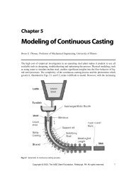
Chapter 14<br />
Fluid Flow in the Mold<br />
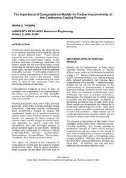
Brian G. Thomas, Pr<strong>of</strong>essor <strong>of</strong> Mechanical Engineering, <strong>University</strong> <strong>of</strong> Illinois<br />
Many quality problems that originate during continuous casting can be directly attributed to poor<br />
control <strong>of</strong> fluid flow conditions. This chapter summarizes some <strong>of</strong> these problems and discusses<br />
the effect <strong>of</strong> continuous casting parameters on controlling the flow. The flow system and its terminology<br />
are illustrated in Fig. 14.1a and b.<br />
The task <strong>of</strong> the flow system is to transport molten steel at a desired flow rate from the ladle into<br />
the mold cavity and to deliver steel to the meniscus area that is neither too cold nor too turbulent.<br />
In addition, the flow conditions should minimize exposure to air, avoid the entrainment <strong>of</strong> slag or<br />
other foreign material, aid in the removal <strong>of</strong> inclusions into the slag layer and encourage uniform<br />
solidification. Achieving these somewhat contradictory tasks requires careful optimization.<br />
14.1 Ladle and Tundish Flow<br />
The importance <strong>of</strong> fluid flow starts in steelmaking and refining vessels including the ladle. The<br />
flow objective in these vessels is to encourage uniform mixing <strong>of</strong> the alloys, to agglomerate inclusions<br />
and to encourage their removal into the slag layer at the top surface. Flow is driven by the<br />
injection <strong>of</strong> gas bubbles or by natural thermal convection. In the absence <strong>of</strong> gas injection, the differences<br />
in density <strong>of</strong> liquid at different temperatures creates significant flow. This tends to stratify<br />
the liquid into distinct layers, where convection cells circulate. The flow challenge then is to<br />
optimize the accompanying gas flow to achieve the flow objectives while minimizing problems<br />
such as disrupting the surface slag layer. A thorough treatment <strong>of</strong> ladle operations is provided in<br />
Chapter 12.<br />
The tundish provides a continuous flow <strong>of</strong> metal from the batch ladle operation to the continuous<br />
casting machine. It also serves as an important metallurgical reaction vessel, where quality can be<br />
improved, maintained or lost. The flow objective in the tundish is to encourage uniformity and<br />
inclusion removal, while avoiding flow-related problems. Tundish flow problems include surface<br />
turbulence, short-circuiting, dead zones and vortexing. Excessive flow directed across the top surface<br />
can produce turbulence and lead to reoxidation and slag entrainment. Short-circuiting allows<br />
incoming steel from the ladle to exit prematurely into the mold with insufficient time for inclusion<br />
flotation. Dead zones are stagnant, colder regions that inhibit inclusion removal and can slowly<br />
mix and contaminate the new steel flowing through the tundish. If the liquid level is too shallow,<br />
high-speed, asymmetric flow may produce vortexing, which can entrain surface slag down into the<br />
mold.<br />
Copyright © 2003, The AISE Steel Foundation, Pittsburgh, PA. All rights reserved. 1
<strong>Casting</strong> Volume<br />
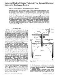
Fig. 14.1a Schematic <strong>of</strong> continuous casting process and terminology showing tundish, submerged entry nozzle,<br />
and mold: View toward wide face; slide gate operation.<br />
Flow behavior in the tundish is governed mainly by the size and shape <strong>of</strong> the vessel and the location<br />
<strong>of</strong> flow-control devices: dams and weirs. The flow pattern is also affected by the steel flow<br />
rate and its temperature distribution. Thermal buoyancy tends to lift up the hotter, lower-density<br />
flowing steel, while colder steel tends to flow down the walls and along the bottom. A temperature<br />
difference <strong>of</strong> only a few degrees is enough to lift the jet flowing beneath the weir and completely<br />
2 Copyright © 2003, The AISE Steel Foundation, Pittsburgh, PA. All rights reserved.
Fig. 14.1b View toward narrow face; stopper rod operation.<br />
Fluid Flow in the Mold<br />
reverse the flow direction in the second chamber <strong>of</strong> the tundish shown in Fig. 14.2a, b and c. 1–3<br />
Flow in the tundish is also greatly affected by the ladle-tundish nozzle geometry and gas in the<br />
ladle stream. Problems related to surface turbulence can be reduced by avoiding excessive argon<br />
levels in the ladle stream and by using fully-shrouded and immersed nozzles. A thorough discussion<br />
<strong>of</strong> tundish operations, including flow phenomena, is found in Chapter 13.<br />
Copyright © 2003, The AISE Steel Foundation, Pittsburgh, PA. All rights reserved. 3
<strong>Casting</strong> Volume<br />
Fig. 14.2 Steady flow distribution in the tundish: a) isothermal model; b) coupled flow-temperature model; and c) temperature<br />
contours corresponding to flow in (b) (1853K inlet into 1833K initial temperature). From Ref. 3.<br />
4 Copyright © 2003, The AISE Steel Foundation, Pittsburgh, PA. All rights reserved.
14.2 Transfer Systems<br />
Steel flows from the ladle, through the tundish and into the mold, where it solidifies, via the path<br />
shown in Fig. 14.1. Flow between vessels is driven by gravity. Between the tundish and mold, this<br />
driving force is proportional to the head <strong>of</strong> liquid metal between the top surface <strong>of</strong> the molten metal<br />
in the tundish and the metal level in the mold. Control <strong>of</strong> the flow rate into the mold is achieved<br />
by metering nozzles, stopper rods or slide gates.<br />
14.2.1 Metering Nozzle Flow Control<br />
Fluid Flow in the Mold<br />
The simplest means to control the flow rate is to choose the appropriate size <strong>of</strong> the opening in the<br />
bottom <strong>of</strong> the tundish that restricts the flow to the desired rate. This inexpensive method is used in<br />
conjunction with open-stream pouring <strong>of</strong> lower-quality steel, where some air entrainment can be<br />
tolerated. Air entrainment can be reduced, but not avoided, by surrounding the stream with argon<br />
gas via one <strong>of</strong> the shrouding methods shown in Fig. 14.3. 4 Of these choices, the bellows appears<br />
to be the most effective.<br />
Metering nozzles have the disadvantage that variations <strong>of</strong> the liquid level in the tundish will produce<br />
variations in flow rate. These flow-rate variations must be compensated for by changes in<br />
withdrawal rate <strong>of</strong> the strand in order to maintain a constant average liquid level in the mold. A<br />
second concern is that the condition <strong>of</strong> the stream is very sensitive to the flow pattern in the tundish<br />
and to any imperfections in the nozzle shape, such as oxide buildup or notches in the outside <strong>of</strong> the<br />
nozzle lip. The condition <strong>of</strong> the stream is important in open pouring because it directly affects the<br />
quality <strong>of</strong> the final steel product.<br />
Different stream conditions are compared in Fig. 14.4. 5 A rough, turbulent stream must be<br />
avoided because (1) its irregular shape entrains much more air, leading to more and larger oxide<br />
inclusions in the product and (2) it creates fluctuations in the liquid level in the mold when it<br />
Fig. 14.3 Free-stream pouring practices between tundish and mold: a) open pouring entrains the most air; b) funnel to<br />
direct stream allows the application <strong>of</strong> mold powder, which reduces turbulence and oxidation at the steel surface; c) pollardtype<br />
argon shroud flushes steel stream with gas; and d) bellows-type argon shroud better protects stream from air exposure.<br />
From Ref. 4.<br />
Copyright © 2003, The AISE Steel Foundation, Pittsburgh, PA. All rights reserved. 5
<strong>Casting</strong> Volume<br />
Fig. 14.4 Open-pour stream condition: a) photograph <strong>of</strong> steel stream between tundish and mold showing irregular shape<br />
<strong>of</strong> rough stream which leads to increased air entrainment; b) stream impacting liquid surface in mold water model showing<br />
greater turbulence and level fluctuations caused by rough stream; and c) stream penetrating beneath surface <strong>of</strong> water<br />
model showing deeper penetration <strong>of</strong> smooth stream. From Ref. 5.<br />
6 Copyright © 2003, The AISE Steel Foundation, Pittsburgh, PA. All rights reserved.
Fluid Flow in the Mold<br />
impacts the surface, leading to nonuniform solidification, surface defects and even breakouts. A<br />
tight, smooth stream entrains less air and creates less disturbance <strong>of</strong> the meniscus region while it<br />
penetrates deeper below the liquid surface. Tight streams are thus very desirable. The funnel in<br />
Fig. 14.3 helps to improve surface quality by substantially lowering meniscus turbulence,<br />
although it has little effect on air entrainment.<br />
14.2.2 Stopper Rod Flow Control<br />
To avoid reoxidation and produce higher quality steel, a protective ceramic nozzle can be used to<br />
shroud the flow <strong>of</strong> steel into the mold. The flow rate is controlled by restricting the opening with<br />
either a stopper rod or a slide gate. The stopper rod system is illustrated schematically in Fig. 14.1b.<br />
Flow control with a stopper rod is slightly more difficult than with slide gates because the stopper<br />
must be manipulated through the entire depth <strong>of</strong> the molten steel in the tundish, and the area <strong>of</strong> the<br />
annular opening that controls the flow is more sensitive to displacement. In addition, a continuous<br />
nozzle does not allow fast exchange <strong>of</strong> SEN tubes and requires some other means for emergency<br />
flow stoppage. However, the stopper rod <strong>of</strong>fers several significant advantages over slide gates:<br />
1. natural prevention <strong>of</strong> molten steel from entering the upper tundish well and freezing<br />
prior to startup without the need for special flow control devices;<br />
2. natural prevention <strong>of</strong> vortex formation above the tundish well and possible slag<br />
entrainment into the nozzle when the liquid level is low;<br />
3. easier sealing to avoid air entrainment due to reduced number <strong>of</strong> moving surfaces;<br />
and<br />
4. more uniform distribution <strong>of</strong> flow to both ports, so that flow entering the mold cavity<br />
is more symmetrical.<br />
14.2.3 Slide Gate Flow Control<br />
Steel flows into the “upper tundish nozzle,” through the slide gate opening, down the long “submerged<br />
entry nozzle” (SEN) tube, and through the SEN ports into the mold cavity, as shown<br />
schematically in Fig. 14.1a. In the three-plate slide gate, pictured in this figure, the central plate is<br />
moved hydraulically to adjust the opening between the upper and lower stationary plates by misaligning<br />
the hole in the sliding plate relative to the nozzle bore. Alternatively, the two-plate slide gate<br />
is missing the lowest plate, so the SEN is attached to the moving plate and travels as the opening is<br />
adjusted. This has the disadvantage <strong>of</strong> continuous variation in the alignment <strong>of</strong> the nozzle relative<br />
to the strand centerline. In both systems,<br />
the joints are all flooded with low-pressure<br />
inert gas (argon) to protect against<br />
air entrainment in the case <strong>of</strong> leaks.<br />
Flow through the slide gate is governed<br />
by the size <strong>of</strong> the overlapped openings<br />
<strong>of</strong> the plates, as illustrated in Fig. 14.5.<br />
This opening size may be quantified in<br />
several different ways. Two popular<br />
measures are “area opening fraction,”<br />
fA , defined by the ratios <strong>of</strong> the shaded<br />
area to the total bore area, and “linear<br />
opening fraction,” fL , defined as the<br />
ratio <strong>of</strong> the distances S to T. For equal<br />
sized openings, these different measures<br />
Fig. 14.5 Quantifying slide gate opening size.<br />
<strong>of</strong> opening fraction are related by:<br />
Copyright © 2003, The AISE Steel Foundation, Pittsburgh, PA. All rights reserved. 7
<strong>Casting</strong> Volume<br />
where<br />
2 -1<br />
Ê L ˆ 2 Ê L ˆ Ê L ˆ<br />
fA<br />
= cos 1 - - 1- 1- 1-<br />
p ËÁ<br />
D¯˜<br />
pËÁ<br />
D¯˜<br />
ËÁ<br />
D¯˜<br />
L R<br />
D D f<br />
Ê ˆ R<br />
= + L<br />
Ë<br />
Á1<br />
¯<br />
˜ -<br />
D<br />
(Eq. 14.1)<br />
(Eq. 14.2)<br />
fA = gate opening (area fraction)<br />
fL = gate opening (linear fraction)<br />
L = length <strong>of</strong> opening (m)<br />
D = nozzle diameter (m)<br />
R = <strong>of</strong>fset distance from nozzle bore to reference line used to measure S and T (m)<br />
Note that fA is always slightly less than L/D, while fL is always more than L/D. The linear opening<br />
fraction, fL in Eq. 14.1, simplifies to exactly L/D if R is zero.<br />
The steel flow rate depends mainly on the height <strong>of</strong> molten steel in the tundish driving the flow and<br />
the pressure drop across the slide gate. Flow rate naturally increases with increasing slide gate<br />
opening position and with increasing tundish depth, as quantified in Fig. 14.6 for typical conditions.<br />
6 The flow rate is also influenced by the nozzle bore size, the amount <strong>of</strong> gas injection, the<br />
constriction <strong>of</strong> the ports, and the extent <strong>of</strong> clogging and wear. The flow rate produced under ideal<br />
conditions, such as presented in Fig. 14.6, can be compared with the measured flow rate in order<br />
to identify the extent <strong>of</strong> nozzle clogging.<br />
14.3 Typical Flow Patterns in the Mold<br />
Typical flow patterns for different molds and operating conditions are shown in Fig. 14.7. Flow is<br />
governed primarily by the condition <strong>of</strong> the jet entering the mold cavity, but is then affected by the<br />
amount <strong>of</strong> gas injection, the section size, the casting speed and electromagnetic forces.<br />
In casting square sections with open-stream pouring, stream penetration is generally shallow. The<br />
surface is turbulent with high velocity flow toward the meniscus, so entrainment <strong>of</strong> mold slag is<br />
likely. With a straight-through nozzle, stream penetration is very deep, and recirculating flow travels<br />
a long distance before flowing upward to the meniscus corners. With a quiet surface, slag<br />
entrainment is unlikely with this condition,<br />
but the meniscus might become too<br />
cold and stagnant. Adding side ports to<br />
the straight-down nozzle produces an<br />
intermediate condition. With shallow<br />
submergence, high casting speed and<br />
excessively large side ports, surface turbulence<br />
and mold slag entrainment are a<br />
danger in small-section billet casting<br />
with this nozzle. In general, the relative<br />
size <strong>of</strong> the side and bottom ports can be<br />
adjusted to optimize the flow condition<br />
and thereby avoid defects.<br />
Fig. 14.6 Effect <strong>of</strong> slide gate opening size and tundish depth on<br />
steel flow rate. From Ref. 6.<br />
2<br />
In slab casting, the mold flow pattern<br />
varies between the two extremes shown<br />
in Fig. 14.7. With an upward-directed jet<br />
exiting the nozzle or a large amount <strong>of</strong><br />
8 Copyright © 2003, The AISE Steel Foundation, Pittsburgh, PA. All rights reserved.
argon gas injection, the<br />
flow will quickly reach<br />
the top surface and<br />
travel away from the<br />
nozzle toward the narrow<br />
faces before being<br />
turned downward. This<br />
“single-roll” flow pattern<br />
is more likely with<br />
multi-port nozzles, or a<br />
bifurcated nozzle with<br />
small, upward-directed<br />
ports. It is also encouraged<br />
by shallow nozzle<br />
submergence, low casting<br />
speed or large mold<br />
widths. Surface velocities<br />
and level fluctuations<br />
are high, so mold<br />
slag entrainment and<br />
surface defects are<br />
likely.<br />
With the other typical<br />
mold flow pattern, the<br />
steel jet enters the mold<br />
cavity from a more<br />
deeply submerged nozzle<br />
with larger or<br />
downward-angled entry<br />
ports <strong>of</strong> a bifurcated<br />
nozzle. The submerged<br />
jet then travels across<br />
the width <strong>of</strong> the mold to<br />
impinge on the narrow<br />
faces. The jet then<br />
splits. Some <strong>of</strong> the flow<br />
travels upward toward<br />
the meniscus and back<br />
across the top surface<br />
toward the nozzle. The<br />
rest <strong>of</strong> the jet flows<br />
down the narrow faces<br />
Fig. 14.7 Types <strong>of</strong> mold flow patterns and nozzles.<br />
deep into the liquid pool. Two large recirculating regions are formed in each symmetric half <strong>of</strong> the<br />
caster, so this flow pattern is termed “double roll.” Often, the flow pattern alternates between the<br />
single- and double-roll archetypes or it may attain some intermediate condition.<br />
14.4 Flow Pattern Prediction and Measurement<br />
Fluid Flow in the Mold<br />
The flow pattern in a given continuous casting mold can be determined in several different ways.<br />
Traditionally, understanding has been deduced from physical models constructed to scale from<br />
transparent plastic using water to simulate the molten steel. Water models have proven to be<br />
Copyright © 2003, The AISE Steel Foundation, Pittsburgh, PA. All rights reserved. 9
<strong>Casting</strong> Volume<br />
accurate for singlephase<br />
flows regardless<br />
<strong>of</strong> the model scale factor,<br />
so long as the flow<br />
is fully turbulent.<br />
Obtaining accurate<br />
flow patterns is very<br />
difficult when gas<br />
injection is significant,<br />
and some phenomena,<br />
such as slag layer<br />
behavior, cannot be<br />
modeled quantitatively,<br />
owing to the<br />
inherent differences in<br />
fluid properties, such<br />
as density and surface<br />
tension.<br />
Mathematical models<br />
can yield added insight<br />
into flow. Computational<br />
models based on<br />
finite-difference or<br />
finite-element solution<br />
<strong>of</strong> the Navier-Stokes<br />
equations can include<br />
phenomena such as<br />
heat transfer, multiphase<br />
flow, and solidification<br />
in steel casting<br />
without the inaccuracies<br />
inherent in a water<br />
model. Accurate calculations<br />
still require significant<br />
effort because<br />
these models need<br />
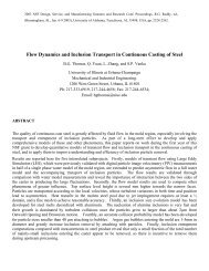
Fig. 14.8 Typical time-average velocities for a double-roll flow pattern determined by a)<br />
mathematical model (direct numerical simulation), and b) water model (particle image<br />
velocimetry). From Ref. 7.<br />
accurate property data, appropriate boundary conditions, numerical validation, experimental calibration<br />
and a lot <strong>of</strong> computer time.<br />
Fig. 14.8 compares the time-averaged flow patterns predicted using physical and mathematical<br />
models for a typical double-roll flow pattern. 7 The water model results are visualized using velocity<br />
vectors from particle image velocimetry. 8,9 The calculated velocities are from a transient simulation<br />
<strong>of</strong> 3-D turbulent flow. 7 Further discussion and examples <strong>of</strong> modeling capabilities were<br />
introduced in Chapter 5.<br />
Flow can also be measured directly in the actual steel caster. Surface velocities can be measured<br />
by monitoring the vibrations <strong>of</strong> a rod inserted into the flow through the top surface. 10 Another<br />
method to measure the molten steel velocity average across the mold thickness is with electromagnetic<br />
(MFC) sensors in the mold walls, 7,11 which monitor the electrical current generated when<br />
steel moves through a magnetic field. The velocity component is then calculated from the time<br />
taken for signal disturbances to move between a pair <strong>of</strong> probes. This method is accurate only in<br />
regions <strong>of</strong> unidirectional flow between the probes, such as found near the surface. Both <strong>of</strong> these<br />
10 Copyright © 2003, The AISE Steel Foundation, Pittsburgh, PA. All rights reserved.
methods require significant effort and<br />
expense to calibrate and operate. Alternatively,<br />
a crude estimate <strong>of</strong> steel flow direction<br />
across the top surface can be obtained using<br />
the same measurement method used to monitor<br />
slag layer thickness. The steel flow direction<br />
can be crudely estimated from the angle<br />
plowed up by the liquid steel as it flows<br />
around an inserted nail, as illustrated in Fig.<br />
14.9. This angle can be captured as a frozen<br />
lump on the bottom <strong>of</strong> the nail, if care is<br />
taken.<br />
14.5 Quality Problems<br />
Related to Mold Flow<br />
Flow in the mold is important for many reasons.<br />
Because it is the last liquid processing<br />
step, poor control <strong>of</strong> flow in the mold can<br />
cause many defects that cannot be corrected.<br />
Problem sources include: the entrapment <strong>of</strong><br />
air argon bubbles and solid inclusion particles<br />
in the solidifying shell, entrainment <strong>of</strong> mold<br />
Fluid Flow in the Mold<br />
slag, surface defects and breakouts due to level fluctuations, inadequate liquid slag layer coverage,<br />
meniscus stagnation, and jet impingement. Each <strong>of</strong> these problems related to fluid flow will be discussed<br />
in turn.<br />
14.5.1 Air Entrainment<br />
Fig. 14.9 Crude measurement <strong>of</strong> flux layer thickness and surface<br />
velocity.<br />
Air entrainment at any stage in steel processing leads to detrimental oxide inclusions in the steel<br />
product. This problem is worst at the final stage <strong>of</strong> flow in the mold, because there is little opportunity<br />
to prevent the reoxidation products from becoming entrapped in the final product as catastrophic<br />
large inclusions.<br />
Open-stream pouring produces the worst air entrainment problems, as previously discussed. This<br />
can be minimized by controlling both flow in the tundish and the metering nozzle design and<br />
operation in order to produce the smooth stream shown in Fig. 14.4. Specifically, high-speed flow<br />
in the tundish across the exit nozzles should be avoided by proper choice <strong>of</strong> flow modifiers and<br />
shape <strong>of</strong> the tundish near the nozzle exit. Castellated metered nozzles, for example, have grooves<br />
that introduce controlled roughness into the stream in order to avoid inconsistent severe roughness.<br />
5<br />
Submerged nozzle casting radically reduces air entrainment. Entrainment is still possible, however,<br />
if there are leaks, cracks, inadequate sealing between the nozzle joints or if the nozzle material<br />
becomes porous. If the internal pressure in the nozzle drops below atmospheric pressure, air will<br />
aspirate through any <strong>of</strong> these pathways into the nozzle. This can be identified by nitrogen pickup,<br />
but the oxygen reacts to form dendritic inclusion particles. Pressure in the nozzle is lowest just<br />
below the flow-control device, due to the venturi effect <strong>of</strong> the metal stream. For a given steel flow<br />
rate, both the pressure drop and the corresponding tundish height increase as the opening area is<br />
restricted, as shown in Fig. 14.10 for a typical slide gate nozzle. 6<br />
Air entrainment into the nozzle can be discouraged by proper introduction <strong>of</strong> an inert gas flow,<br />
which is one <strong>of</strong> the ways in which argon gas acts to prevent nozzle clogging (see Chapter 9).<br />
Copyright © 2003, The AISE Steel Foundation, Pittsburgh, PA. All rights reserved. 11
<strong>Casting</strong> Volume<br />
Fig. 14.10 Pressure drop calculated down nozzle: a) pressure contours in centerplane showing that major variations<br />
are in vertical direction; and b) effect <strong>of</strong> slide gate opening on vertical pressure distribution. From Ref. 6.<br />
Adding argon gas can raise the minimum pressure in the nozzle above ambient, as shown in Fig.<br />
14.11. 12 Note that this occurs because the slide gate must open up to accommodate the gas (shown<br />
at the top <strong>of</strong> Fig. 14.11), in addition to the pressurizing effect <strong>of</strong> the gas. 6<br />
The minimum gas flow rate calculated to avoid a partial vacuum is shown in Fig. 14.12. 6 When<br />
the bore opening is either very small or very large, the pressure never drops below one atmosphere<br />
(zero gauge pressure), so gas injection is not needed to prevent aspiration. Less gas is<br />
needed at low casting speed and at low tundish level, when the pressure drops are lower. Maintaining<br />
a high gas flow rate during these times may disrupt flow in the mold and be detrimental<br />
to steel quality.<br />
Design <strong>of</strong> the nozzle and flow control geometry should promote smooth flow with minimal recirculation,<br />
in order to both minimize the pressure drops that allow reoxidation and to discourage<br />
12 Copyright © 2003, The AISE Steel Foundation, Pittsburgh, PA. All rights reserved.
Fluid Flow in the Mold<br />
Fig. 14.11 Increase in nozzle pressure caused by argon gas injection and accompanying increase in gate opening. Each<br />
line on the top <strong>of</strong> the figure indicates the slide gate position corresponding to a different tundish level. From Ref. 6.<br />
clogging. A sufficiently thick slag layer over the surface <strong>of</strong> the steel in the mold is also important.<br />
Finally, flow in the mold should be controlled to avoid surface turbulence that could entrain air.<br />
14.5.2 Entrapment <strong>of</strong> Bubbles and Inclusions<br />
14.5.2.1 Surface Entrapment<br />
Most surface defects in the steel product originate in the mold at the meniscus, where the solidifying<br />
steel shell is very thin. The most obvious source <strong>of</strong> surface defects is the capture <strong>of</strong> foreign particles<br />
into the solidifying shell at the meniscus. Particles come from many sources, including argon<br />
bubbles and oxide inclusions generated by prior processes that are carried in with the steel entering<br />
the mold cavity. While argon bubbles naturally float, they sometimes have difficulty penetrating<br />
Copyright © 2003, The AISE Steel Foundation, Pittsburgh, PA. All rights reserved. 13
<strong>Casting</strong> Volume<br />
Fig. 14.12 Optimizing gas injection. From Ref. 6.<br />
through into the slag layer, especially if they are small. If the meniscus is unstable, stagnant, or has<br />
a solidified lip or “hook,” bubbles may be captured, forming pinholes just beneath the surface <strong>of</strong> the<br />
slab, as shown in Fig. 14.13a. 13 Inclusion particles have less buoyancy, so they are even easier to<br />
capture, as shown in Fig. 14.13b. 13 If they are not removed by scale formation or during scarfing,<br />
these surface inclusions will lead to line defects or “slivers” in the final product.<br />
14.5.2.2 Internal Entrapment<br />
Most <strong>of</strong> the bubbles and many <strong>of</strong> the inclusions<br />
carried into the mold eventually circulate near<br />
the top surface and float out into the slag layer.<br />
This is illustrated in Fig. 14.14. 14 Some particles<br />
are carried deep into the liquid pool, however,<br />
where eventually they may become entrained in<br />
the solidifying strand. Even gas bubbles traveling<br />
with the incoming jet occasionally are carried<br />
into the lower recirculation zone. In a<br />
curved caster, large particles in the lower recirculation<br />
zone will spiral toward the inner radius,<br />
where they may become trapped in the solidifying<br />
shell. This is illustrated by one <strong>of</strong> the trajectories<br />
in Fig. 14.14. 14 Entrapment is more likely<br />
at high liquid flow rates, especially when casting<br />
at high speeds, with wide slabs, with asymmetric<br />
flow conditions such as accompany nozzle<br />
clogging, or with transient conditions such as<br />
raising the casting speed. Entrapped solid oxide<br />
particles eventually lead to surface slivers or<br />
internal defects, which act as stress concentration<br />
sites to reduce fatigue and toughness properties<br />
<strong>of</strong> the final product.<br />
Fig. 14.13 Surface defects in steel slab caused by particles<br />
trapped beneath frozen meniscus: a) argon bubble<br />
trapped beneath oscillation mark hook; and b) slab surface<br />
inclusion. From Ref. 13.<br />
14 Copyright © 2003, The AISE Steel Foundation, Pittsburgh, PA. All rights reserved.
Most particles are captured 1–3 m below the meniscus,<br />
independent <strong>of</strong> casting speed. 14,15 Gas bubbles<br />
captured in this way eventually may cause blister<br />
defects such as “pencil pipe,” which appear as<br />
streaks in the final rolled product. When the slab is<br />
rolled, the subsurface bubbles elongate and the layer<br />
<strong>of</strong> metal separating them from the surface becomes<br />
thinner. Later during annealing, they can expand to<br />
raise the surface <strong>of</strong> the sheet locally, especially if<br />
the steel is weak such as ultra-low-carbon grades, or<br />
if hydrogen is present. 16 Trapped alumina inclusions<br />
or mold slag particles have been associated with<br />
similar defects. 17 This problem can be greatly<br />
reduced by lowering the liquid mass flow rate 18<br />
and/or by ensuring that at least the top 2.5-m section<br />
<strong>of</strong> the caster is straight (vertical), in order to avoid<br />
the spiraling entrapment mechanism.<br />
14.5.3 Entrainment <strong>of</strong> Mold Slag<br />
Mold slag can be entrained into the solidifiying<br />
shell due to vortexing, high-velocity flow that<br />
shears slag from the surface, and turbulence at the<br />
meniscus. The capture <strong>of</strong> large inclusions into the<br />
solidifying shell then leads to obvious line defects<br />
or “slivers” in the final product.<br />
Vortexing most <strong>of</strong>ten occurs during conditions <strong>of</strong><br />
asymmetrical flow, where steel flows rapidly<br />
through the narrow passage between the SEN and<br />
the mold. This creates swirling just beside the SEN,<br />
as shown in Fig. 14.15a. 19 This swirl or vortex may<br />
draw mold slag downward, near the sides <strong>of</strong> the<br />
nozzle. If it is then entrained with the jets exiting the<br />
nozzle ports, this slag will be dispersed everywhere<br />
and create defects. In addition to the vortex, slag<br />
may also be drawn downward by the recirculation<br />
Fluid Flow in the Mold<br />
Fig. 14.14 Sample trajectories <strong>of</strong> five particles carried<br />
into the liquid pool, showing one large particle spiraling<br />
in lower recirculation zone toward solidifying shell on<br />
inside radius wideface. From Ref. 14.<br />
pattern that accompanies flow from the nozzle ports. Thus, slag entrainment is most likely with<br />
shallow nozzle submergence and high casting speed.<br />
The entrainment <strong>of</strong> mold slag also occurs when the velocity across the top surface becomes high<br />
enough to shear mold slag fingers down into the flow, where they can be entrained. Fig. 14.16 illustrates<br />
this mechanism. 20 Once it has broken up into particles and been dispersed into the flow, much<br />
<strong>of</strong> this slag may become internal inclusion defects. To avoid shearing slag in this manner, the surface<br />
velocity must be kept below a critical value. This critical velocity has been measured in wateroil<br />
models as a function <strong>of</strong> viscosity and other parameters. 21,22 Entrainment is easier for deeper slag<br />
layers, lower slag viscosity and lower slag surface tension. The critical velocity may also be<br />
exceeded when the standing wave becomes too severe and the interface emulsifies, as sketched in<br />
Fig. 14.15b. 23,24 The critical velocity also depends on the relative densities <strong>of</strong> the steel and flux<br />
phases and the mold geometry. 24,25<br />
High-velocity surface flows may also cause emulsification <strong>of</strong> the slag, where slag and steel intermix<br />
and even create a foam, if too much argon gas is present. 17 This allows easy capture <strong>of</strong> particles via<br />
vortexing or surface shearing flow. Another mechanism for slag entrainment, meniscus turbulence,<br />
Copyright © 2003, The AISE Steel Foundation, Pittsburgh, PA. All rights reserved. 15
<strong>Casting</strong> Volume<br />
is related to level variations.<br />
This will be discussed in the<br />
next section.<br />
14.5.4 Level<br />
Variations<br />
Many surface defects form at<br />
the meniscus due to variations<br />
in the level <strong>of</strong> the liquid steel<br />
on the top surface <strong>of</strong> the mold<br />
cavity. These variations take<br />
two forms: steady variation<br />
across the mold width known<br />
as a “standing wave,” and<br />
“level fluctuations,” where the<br />
local level changes with time.<br />
While the standing wave can<br />
cause chronic problems with<br />
liquid slag feeding (see the<br />
next section), the time-varying<br />
level fluctuations cause<br />
the most serious surface<br />
defects. To avoid these problems,<br />
the top surface velocity<br />
should be kept below a critical<br />
maximum velocity, which<br />
has been estimated to be 0.3 m/s (see Ref. 19) or 0.4 m/s (see Ref. 26).<br />
14.5.4.1 Defects from Level Fluctuations<br />
Steady, controlled oscillation <strong>of</strong> the mold generates<br />
ripples across the liquid level but does not present an<br />
inherent quality problem, because the liquid adjacent<br />
to the mold wall tends to move with the wall. Sudden<br />
jumps or dips in liquid level are much more serious,<br />
however.<br />
A sudden jump in local level can cause molten steel to<br />
overflow the meniscus. In the worst case, the steel can<br />
stick to the mold wall and start a sticker breakout.<br />
Alternatively, a jump in level can cause an irregular<br />
extended frozen meniscus shape, or “hook.” This<br />
extended meniscus can capture mold powder or possibly<br />
bubbles or inclusions, such as shown in Fig.<br />
14.13. 13,27 Variations <strong>of</strong> more than the oscillation<br />
stroke over a time interval on the order <strong>of</strong> one second<br />
are the most detrimental. Even low-frequency variations<br />
(period > 60 s) may cause defects if the meniscus<br />
overflows and the solid slag rim is imprinted on the<br />
shell or captured. 28 The microstructure associated with<br />
overflow <strong>of</strong> the meniscus is shown in Fig. 14.17 for a<br />
billet with a lap defect. 29<br />
(b)<br />
Fig. 14.15 Mold slag entrainment due to detrimental high-speed asymmetric flow<br />
pattern: a) vortexing at the top surface (from Ref. 19), and b) asymmetric oscillatory<br />
flow in the liquid pool (from Ref. 23).<br />
Fig. 5.16 Steps in slag entrainment due to excessive<br />
surface flow. From Ref. 20.<br />
16 Copyright © 2003, The AISE Steel Foundation, Pittsburgh, PA. All rights reserved.
Fluid Flow in the Mold<br />
A sudden severe drop in liquid level exposes the inside <strong>of</strong> the solidifying shell to the mold slag and<br />
also leads to surface depressions. Relaxing the temperature gradient causes cooling and bending <strong>of</strong><br />
the top <strong>of</strong> the shell toward the liquid steel. When the liquid level rises back, the solidification <strong>of</strong><br />
new hot solid against this cool solid surface layer leads to even more bending and stresses when<br />
the surface layer reheats. 30 This sequence <strong>of</strong> events is illustrated on a 20-mm-long section <strong>of</strong> shell<br />
in the calculation results in Fig. 14.18, for a 20- to 30-mm level drop lasting 0.6 sec. 30 When liquid<br />
steel finally overflows the meniscus to continue with ordinary solidification, a surface depression<br />
is left behind, such as that shown in Fig. 14.19.<br />
The microstructural changes and surface depressions associated with level variations are serious<br />
because they initiate other quality problems in the final product. These problems include surface<br />
cracks and segregation. Surface cracks allow air to penetrate beneath the steel surface, where it<br />
forms iron oxide, leading to line defects in the final product. These defects are difficult to distinguish<br />
from inclusion-related defects, other than by the simpler composition <strong>of</strong> their oxides.<br />
14.5.4.2 Detection <strong>of</strong> Level Fluctuations<br />
Fig. 5.17 Microstructure associated with overflow <strong>of</strong><br />
the meniscus, shown for a lap depression defect in<br />
a billet. From Ref. 29.<br />
Level variations can be measured by examination <strong>of</strong> the level control sensor signals, thermocouple<br />
signals and the final condition <strong>of</strong> the slab surface. Mold level can be measured directly in several<br />
different ways, which include the popular NKK eddy-current sensor, 31 radioactive source detection,<br />
32 electromagnetic methods such as the EMLI detector, 33 and other methods. 34<br />
The measurement <strong>of</strong> level fluctuations should not be confused with the measurement <strong>of</strong> the moving-average<br />
liquid level in the mold, which is used to control movement <strong>of</strong> the flow-control device<br />
(slide gate or stopper rod). Control <strong>of</strong> the total flow rate requires measurement <strong>of</strong> the average liquid<br />
level. This is best accomplished by measuring where the liquid steel surface level is the most<br />
stable (typically midway between the SEN and the narrow face) and by filtering (time-averaging)<br />
the signal. The objective <strong>of</strong> this sensor signal is to remove the influence <strong>of</strong> local fluctuations, which<br />
are not directly related to the average level needed by flow control device. However, these local<br />
transient fluctuations are very important to surface quality. Thus, quality detection systems should<br />
always monitor the unfiltered signal from the level sensor. Even better is to monitor the unfiltered<br />
signal from a second sensor, positioned where the level fluctuations are greatest, usually near the<br />
narrow face. 26<br />
Vertical rows <strong>of</strong> thermocouples embedded in the copper mold walls near the meniscus <strong>of</strong>fer an<br />
indirect, but much less expensive, way to monitor level variations around the perimeter <strong>of</strong> the<br />
Copyright © 2003, The AISE Steel Foundation, Pittsburgh, PA. All rights reserved. 17
<strong>Casting</strong> Volume<br />
Fig. 14.18 Events calculated to occur during a severe, level drop (20 mm for 0.6 sec) that lead to a transverse surface<br />
depression. From Ref. 30.<br />
18 Copyright © 2003, The AISE Steel Foundation, Pittsburgh, PA. All rights reserved.
Fig. 14.19 Severe transverse depression defect on a bloom surface.<br />
Fluid Flow in the Mold<br />
Copyright © 2003, The AISE Steel Foundation, Pittsburgh, PA. All rights reserved. 19
<strong>Casting</strong> Volume<br />
Fig. 14.20 Mold thermocouple signals correlated with level sensor measurement. From Ref. 35.<br />
mold. The temperature pr<strong>of</strong>ile down the row <strong>of</strong> thermocouples can be used to indicate where the<br />
meniscus is located. Fig. 14.20 shows how the signal variations from the mold level sensors correspond<br />
with temperature variations measured in the mold wall. 35 The measured temperature variations<br />
lose sensitivity with increasing distance away from the meniscus, either beneath the mold<br />
hot face surface, or down the mold.<br />
The quality <strong>of</strong> liquid level control can also be gathered by observing the oscillation marks on the<br />
exterior surface <strong>of</strong> the slab, which should be straight and regular with a spacing or “pitch” defined<br />
by the casting speed and oscillation frequency. Overlapping or wiggly oscillation marks indicate a<br />
serious flow problem in the mold. The variable pitch <strong>of</strong> the deep, severely-distorted oscillation<br />
marks in Fig. 14.19, for example, shows evidence <strong>of</strong> time periods when the liquid level is generally<br />
rising (where the oscillation marks are spaced further apart) and falling (where they are closer<br />
together). 28 In addition, the height <strong>of</strong> the standing wave is easily measured by variations in straightness.<br />
For example, the curved oscillation marks in Fig. 14.19 show evidence <strong>of</strong> a generally higher<br />
liquid level on the edges <strong>of</strong> the bloom, which is due in this case to mold electromagnetic stirring<br />
raising the liquid level in the corners.<br />
14.5.4.3 Causes <strong>of</strong> Level Variations<br />
Level variations have many causes that are not fully understood. High-frequency fluctuations due<br />
to the turbulent nature <strong>of</strong> the flow increase with increasing velocity across the top surface, which<br />
depends on the jet velocity and the mold flow pattern. 26 Sudden transient events such as the loosening<br />
<strong>of</strong> nozzle clogs or sudden changes in casting speed also cause sudden local level fluctuations.<br />
Lubrication problems in both oil and powder casting lead to level variation defects. Electromagnetic<br />
stirring too close to the meniscus can generate severe standing waves. 36 Even problems with<br />
feedback in the level control system can generate fluctuations.<br />
Lower frequency level fluctuations can be caused by synchronized bulging and squeezing <strong>of</strong> the<br />
strand below the mold, which acts like an accordian bellows to alternately raise and lower the<br />
level in the mold. This problem is most likely to occur just after casting speed changes, due to<br />
bulging variations moving through the rolls. This was likely the root cause <strong>of</strong> periodic defects<br />
similar to those in Fig. 14.19. 28 This can be minimized by avoiding constant roll pitch that amplifies<br />
the effect and by minimizing temporary slow downs in casting speed. Complete strand stoppage<br />
is particularly detrimental because roll bending will then contribute to the bulging and the<br />
associated level variations.<br />
20 Copyright © 2003, The AISE Steel Foundation, Pittsburgh, PA. All rights reserved.
14.5.5 Inadequate Lubricant<br />
Fluid Flow in the Mold<br />
To maintain consistent mold heat transfer and avoid surface cracks, the infiltration <strong>of</strong> liquid mold<br />
slag into the gap between the shell and the mold must be kept uniform. To do this requires an optimum<br />
delivery <strong>of</strong> lubricant to the meniscus perimeter. Indeed, problems with the oil lubrication system<br />
are believed to be responsible in part for the defects associated with the meniscus overflow in<br />
Fig. 14.17. 29 In powder casting, it is important to have an adequate coverage <strong>of</strong> molten slag combined<br />
with an optimized oscillation practice and controlled resolidified slag rim. The many severe<br />
consequences <strong>of</strong> inadequate lubricant include breakouts, cracks and surface depressions and are<br />
discussed in detail elsewhere. 37,38<br />
The depth <strong>of</strong> the liquid slag layer can be monitored by dipping steel nails together with aluminum<br />
and/or copper wires vertically down through the slag layer, as shown in Fig. 14.9. The 1- to 5-second<br />
dipping time is critical and should be optimized experimentally. The aluminum wire does not<br />
melt above the liquid slag/powder interface only because heat transfer through the low-conductivity<br />
powder layer is too slow if the dipping time is short enough. The steel/liquid slag interface is<br />
identified by the lump <strong>of</strong> steel solidified to its end. The entire pr<strong>of</strong>ile <strong>of</strong> the slag layer can be found<br />
by inserting a board containing many nails, or by using sheets <strong>of</strong> steel and aluminum instead <strong>of</strong><br />
nails.<br />
The liquid slag layer should be deep enough everywhere to withstand the largest level fluctuations<br />
without the steel touching the powder layer. It should also be kept constant with time, as<br />
transients <strong>of</strong> any nature can lead to defects. Fig. 14.21 shows the consequences <strong>of</strong> intermittent<br />
powder additions on liquid slag layer variations. 39 A deeper, more uniform liquid slag layer is<br />
encouraged by a deeper powder layer and by a level, steady, liquid steel flow across its top surface.<br />
39 In addition, the powder melting rate, liquid slag viscosity and its solidification temperature<br />
should be optimized for the casting conditions and steel grade. 38 Crystalline slags with a<br />
high solidification temperature are recommended for depression-sensitive grades, such as peritectic<br />
and austenitic stainless steels. 37 Glassy slags, with a low viscosity at 1300°C, are recommended<br />
for other sticker-sensitive grades. Further discussion <strong>of</strong> this important issue is found<br />
elsewhere. 37<br />
Fig. 14.21 Variation in flux layer thickness caused by intermittent powder addition, compared with<br />
steady-state maximum thickness. From Ref. 39.<br />
Copyright © 2003, The AISE Steel Foundation, Pittsburgh, PA. All rights reserved. 21
<strong>Casting</strong> Volume<br />
14.5.6 Meniscus Stagnation<br />
If the steel jets entering the mold cavity move too close to the meniscus, slag entrainment and surface<br />
defects from level fluctuations may result, as previously discussed. On the other hand, if the<br />
steel jet is directed too deeply or has too little superheat, then the liquid surface will have very little<br />
motion and will become too cold. This can lead to inadequate melting <strong>of</strong> the powder, which<br />
relies on fluid flow to generate convective heat transfer to help transport heat across the liquid slag<br />
layer to melt the powder. 39 In addition, this can lead to freezing <strong>of</strong> the steel meniscus, which will<br />
aggravate the formation <strong>of</strong> hooks and associated defects shown in Fig. 14.13. 13 For example,<br />
decreasing surface velocity below 0.4 m/s has been measured to increase surface pinhole defects. 40<br />
To avoid these problems, the flow pattern should be designed to exceed a critical minimum velocity<br />
across the top surface, estimated to be about 0.1–0.2 m/s. 26 This can be achieved by designing the<br />
nozzle geometry to deliver an upward jet, as discussed in the next section. Alternatively, the superheat<br />
can be increased, although this tends to worsen problems with centerline segregation. Finally,<br />
higher surface velocity can be achieved by increasing casting speed, increasing argon gas flow rate,<br />
applying electromagnetic forces or reducing submergence depth.<br />
14.5.7 Jet Impingement<br />
Impingement <strong>of</strong> the molten steel jets onto the solidifying shell in the mold sometimes causes problems<br />
if the jet is either too hot or too cold. Breakouts occur when the steel shell at mold exit is not<br />
strong enough to contain the liquid steel. Breakouts have many causes, which are discussed in<br />
detail in Chapter 19. Sticker breakouts may initiate from a severe level fluctuation or slag lubrication<br />
problem. Another cause is local thin and hot regions <strong>of</strong> the solidifying shell, which can result<br />
from high superheat dissipation at the region where an excessively hot jet impinges on the inside<br />
<strong>of</strong> the shell. 41–43 Problems arise only if this local superheat dissipation is combined with slow heat<br />
extraction from the corresponding shell exterior. This problem is most likely in the <strong>of</strong>f-corner<br />
regions, where the jet may impinge and the shell shrinkage also creates a larger gap.<br />
As the steel flows from the nozzle through the mold, it quickly dissipates its superheat and drops<br />
in temperature, as shown in Fig. 14.22. 42 The coldest liquid is naturally found deep in the caster,<br />
at the meniscus, and at the top surface beside the inlet nozzle. The fluid is coldest here because it<br />
is both far from the inlet and stagnant. When a cold nozzle is inserted during an SEN exchange,<br />
the cool steel in this region is prone to skull formation, meniscus freezing and even “bridging,”<br />
where steel or slag freezes across the shortest distance between the nozzle and meniscus <strong>of</strong> the<br />
wide face, <strong>of</strong>ten leading to a breakout. The narrow face meniscus is prone to deeper hooks, especially<br />
on wide slabs with low superheat.<br />
Almost all <strong>of</strong> the superheat is dissipated to the shell in the mold or just below, as shown in Fig.<br />
14.23. 42 In slab casting with bifurcated nozzles, the impingement region on the narrow face absorbs<br />
the most superheat. This region extends to the <strong>of</strong>f-corner region <strong>of</strong> the wide face, as shown in Fig.<br />
14.22. Fig. 14.24 shows how shell growth depends on the combined effects <strong>of</strong> superheat input from<br />
jet impingement and heat removal to the mold walls. 42 Jet impingement produces a thinner shell<br />
on the narrow face, compared with classic parabolic shell growth on the wide face, as shown in<br />
Fig. 14.25. 44 The importance <strong>of</strong> this effect increases with higher casting speeds, higher superheats<br />
and lower gap heat transfer. 42,43 Asymmetric flow, such as that caused by nozzle clogging, also<br />
aggravates this effect.<br />
14.6 Flow System Design<br />
The flow system should be designed to avoid the problems outlined in the previous section. To<br />
achieve this, several different objectives should be satisfied.<br />
22 Copyright © 2003, The AISE Steel Foundation, Pittsburgh, PA. All rights reserved.
Fluid Flow in the Mold<br />
Fig. 14.22 Fluid flow velocities, temperatures and superheat fluxes delivered to the inside <strong>of</strong> the solidifying shell calculated<br />
in the mold region <strong>of</strong> a continuous slab caster (220 x 1320-mm slab cast at 1.0 m/min). From Ref. 42.<br />
The first requirement is to minimize transients during the operation. Sudden changes are the main<br />
cause <strong>of</strong> the flow instabilities which generate surface turbulence. Because flow parameters can be<br />
optimized only for steady operation, each <strong>of</strong> the parameters which affects fluid flow must be controlled<br />
simultaneously. It is especially important to keep nearly constant the liquid steel level in the<br />
mold, powder feeding rate (to keep a constant liquid slag layer thickness), casting speed, gas injection<br />
rate, slide gate opening, and nozzle position (alignment and submergence).<br />
Next, the steady mold flow pattern must be designed and controlled. It is affected by both nozzle<br />
design and operating conditions, which are discussed in the following sections. Nozzle geometry<br />
influences the flow pattern in the mold, which is greatly responsible for controlling surface turbulence<br />
and the accompanying defects. The flow pattern also depends on parameters which generally<br />
cannot be adjusted to accommodate the flow pattern, such as the position <strong>of</strong> the flow control device<br />
(slide gate or stopper rod), nozzle clogging, casting speed, strand width, and strand thickness. Fortunately,<br />
other parameters besides nozzle geometry can be adjusted to maintain an optimal the flow<br />
Copyright © 2003, The AISE Steel Foundation, Pittsburgh, PA. All rights reserved. 23
<strong>Casting</strong> Volume<br />
Fig. 14.23 Calculated distribution <strong>of</strong> superheat<br />
delivery to the shell. From Ref. 42.<br />
Fig. 14.25 Breakout shell thickness<br />
pr<strong>of</strong>iles showing thin<br />
region near location <strong>of</strong> jet<br />
impingement on narrow face,<br />
relative to steady shell growth<br />
down wide face. From Ref. 44.<br />
Fig. 14.24 Schematic <strong>of</strong> heat transfer through solidifying shell (narrow face)<br />
showing isotherms and heat flux pr<strong>of</strong>iles. From Ref. 42.<br />
24 Copyright © 2003, The AISE Steel Foundation, Pittsburgh, PA. All rights reserved.
Fluid Flow in the Mold<br />
pattern. These include the injection <strong>of</strong> argon gas, nozzle submergence depth, and the application<br />
<strong>of</strong> electromagnetic forces.<br />
14.7 Submerged Entry Nozzle Design<br />
One <strong>of</strong> the most important functions <strong>of</strong> the nozzle is to<br />
promote a good flow pattern in the mold cavity. The jet<br />
flowing from the nozzle should have a flow rate, direction<br />
and other properties that have been optimized to<br />
achieve this, according to considerations discussed in<br />
the next section. In addition, the nozzle should discourage<br />
any large transient fluctuations, flow asymmetry<br />
or high turbulence levels. The shape <strong>of</strong> the nozzle<br />
is one <strong>of</strong> the few casting design variables that has an<br />
important impact on quality and yet can be easily<br />
changed at low cost over a wide spectrum <strong>of</strong> design<br />
shapes. Flow through a typical slide-gate nozzle,<br />
including the internal distribution <strong>of</strong> argon gas, and the<br />
outlet jets, is illustrated in Fig. 14.26. 6 This section discusses<br />
the influence <strong>of</strong> the following design variables<br />
on the condition <strong>of</strong> the jet entering the mold cavity:<br />
Bore size<br />
Port angle<br />
Port opening size<br />
Nozzle wall thickness<br />
Port shape (round, oval, square)<br />
Number <strong>of</strong> ports (bifurcated or multiport)<br />
Nozzle bottom design<br />
The initial choice <strong>of</strong> nozzle design should be made<br />
with the aid <strong>of</strong> both physical and mathematical models,<br />
as discussed in Chapter 5. It should naturally perform<br />
well over the entire range <strong>of</strong> operation expected.<br />
When the operating range is very wide, it is better to<br />
use two or more different designs.<br />
14.7.1 Bore Size<br />
The first design consideration is capacity. Since the flow is driven by gravity alone (and can only<br />
be throttled down), the nozzle cross-section should be large enough to accommodate the maximum<br />
desired flow rate to meet productivity demands. Larger-diameter nozzles are naturally needed for<br />
higher casting speed. To fit more easily into the mold cavity and minimize the danger <strong>of</strong> bridging,<br />
nozzles for thin-slab and high-speed casting need elongated bores, such as 80 x 130 mm, with the<br />
smaller dimension spanning less <strong>of</strong> the mold thickness. Oversized nozzle bores are sometimes used<br />
to accommodate some alumina buildup. However, this restricts the operation <strong>of</strong> the nozzle, which<br />
thereby aggravates flow variations and negative pressure problems.<br />
14.7.2 Nozzle Port Angle and Opening Size<br />
Fig. 14.26 Simulated flow field for a typical nozzle<br />
(16% gas; 50% open; 90° slide gate; 78-mm bore;<br />
78-mm square ports): (a) argon gas distribution; (b)<br />
velocities in center plane parallel to WF; (c) velocities<br />
in center plane parallel to NF; and (d) velocities<br />
at port outlet plane. From Ref. 6.<br />
The nozzle ports should be designed to deliver steel jets into the mold cavity in the desired direction<br />
with the desired level <strong>of</strong> internal turbulence, velocity, mass flow, spread and swirl. More<br />
Copyright © 2003, The AISE Steel Foundation, Pittsburgh, PA. All rights reserved. 25
<strong>Casting</strong> Volume<br />
Fig. 14.27 Nozzle angle effect on flow exiting nozzle. From Ref. 46.<br />
importantly, they should deliver these jets evenly with as few variations in jet properties over time<br />
as possible. The angle and size <strong>of</strong> the ports is very influential in achieving this.<br />
The total area <strong>of</strong> the nozzle port exits is <strong>of</strong>ten made much larger than that <strong>of</strong> the bore, in order to<br />
accommodate some alumina buildup. As a consequence, the flow generally exits through only the<br />
bottom <strong>of</strong> the nozzle port, 45 as shown in Fig. 14.26b. 6 Flow recirculation occurs in the top half,<br />
where steel actually flows into the nozzle. 46 Stagnant regions such as these may aggravate clogging.<br />
47,48<br />
Because flow at the top <strong>of</strong> the nozzle exit ports is slow and directed into the nozzle, the angle <strong>of</strong><br />
the upper edge <strong>of</strong> the exit port has less effect on the angle <strong>of</strong> the flow leaving the nozzle than the<br />
bottom edge. 46 However, the shape <strong>of</strong> this top edge is important, as a smooth curve promotes<br />
attachment <strong>of</strong> the jet to the nozzle walls. This produces less recirculation and greater flow rate<br />
through the port with the curved top edge, such as caused by clogging. 49<br />
A second consequence <strong>of</strong> large exit ports is that the nominal angle <strong>of</strong> the edges <strong>of</strong> the outlet port<br />
has less effect on the jet direction. Fig. 14.27 shows that the momentum <strong>of</strong> the downward flow<br />
through the nozzle with oversized ports carries the steel jet into the mold at a downward angle,<br />
regardless <strong>of</strong> the angle <strong>of</strong> the port edges. 46 For the 90-mm-high ports shown, flow into the mold is<br />
angled downward even when the port is angled upward. When the port edges are angled downward,<br />
the downward angle <strong>of</strong> the steel flow is always steeper.<br />
When the port size is reduced such that the total port area is less than the bore area, then the angle<br />
<strong>of</strong> the nozzle ports becomes more important, as the flow is forced to conform more closely to the<br />
angle <strong>of</strong> the port edges. 49 Fig. 14.28 shows that the jet leaving a 45-mm-high upward-angled nozzle<br />
heads upward, instead <strong>of</strong> downward for the equivalent 90-mm-high port. For this reason, flow<br />
from multiport nozzles tends to conform more closely to the direction <strong>of</strong> the nozzle port edges,<br />
since each <strong>of</strong> the exit ports is smaller and is thus more effective at influencing the flow. However,<br />
the speed and turbulence levels <strong>of</strong> the jets exiting the nozzle both increase with the smaller ports.<br />
When the port edges are effective, then steepening the port angle directs the jet deeper into the liquid<br />
cavity, and the flow pattern shifts downward. Of greater importance, the velocity across the top<br />
surface decreases slightly. 50<br />
14.7.3 Nozzle Wall Thickness<br />
Increasing the thickness <strong>of</strong> the nozzle wall makes the nozzle port edges more effective at controlling<br />
the jet direction. 49 As shown in Fig. 14.29, the 12-mm nozzle has a steeper downward jet,<br />
26 Copyright © 2003, The AISE Steel Foundation, Pittsburgh, PA. All rights reserved.
Fluid Flow in the Mold<br />
while the thick-walled nozzle has more desirable uniform flow in the same direction as the port<br />
angle. The wall thickness also has three other important effects. It affects the size <strong>of</strong> the space in<br />
the critical region between the nozzle and meniscus, the thermal shock resistance <strong>of</strong> the refractories,<br />
and the erosion resistance at the slag line.<br />
14.7.4 Port Shape<br />
For oversized nozzle ports with the same outlet area (and other geometric parameters constant), tall<br />
and thin ports induce a steeper downward jet angle than short, fat ports. 6,45 This is quantified in Fig.<br />
14.30 for a 50% open slide gate, cast at 1 m/min. through a bifurcated nozzle with 78-mm bore and<br />
15° downward ports. 6 Circular ports generate more swirl and have a larger spread angle than rectangular<br />
ports having the same port area. 49 All ports tend to become smaller and rounder with time,<br />
however, due to clogging. Port shape is less important than port size and angle in controlling the<br />
flow. 51<br />
14.7.5 Number <strong>of</strong> Ports<br />
Multiport nozzles tend to control the flow direction more closely than do bifurcated nozzles, as discussed<br />
previously. A central hole added to the bottom <strong>of</strong> a bifurcated nozzle will encourage symmetry<br />
and stability in the mold flow pattern. At high casting speed, in wide molds, or in thin slabs,<br />
the mold flow pattern tends to oscillate periodically from side to side. 23,52 The extra central hole<br />
makes this oscillation more difficult, leading to fewer surface-level fluctuations.<br />
In addition, the bottom hole sends some <strong>of</strong> the jet momentum deeper and consequently reduces the<br />
intensity <strong>of</strong> the flow near the surface. In square-section billet casting, the relative sizes <strong>of</strong> the side<br />
and bottom ports can be adjusted to control the jet momentum in order to optimize surface flow<br />
intensity.<br />
(a) (b)<br />
Fig. 14.28 Port size effect on jets exiting nozzle (15° up, 1.0 m/min): a) short (45 mm) port height, and b) tall (90 mm) port<br />
height. From Ref. 49.<br />
Copyright © 2003, The AISE Steel Foundation, Pittsburgh, PA. All rights reserved. 27
<strong>Casting</strong> Volume<br />
Fig. 14.30 Port shape effect on jet angle leaving<br />
nozzle. From Ref. 6.<br />
Fig. 14.29 Nozzle bore thickness effect on straightening flow<br />
exiting nozzle. From Ref. 49.<br />
28 Copyright © 2003, The AISE Steel Foundation, Pittsburgh, PA. All rights reserved.
14.7.6 Nozzle Bottom Design<br />
The shape <strong>of</strong> the bottom <strong>of</strong> the nozzle has little effect on the mass flow and direction <strong>of</strong> the jets<br />
leaving the nozzle. 46 However, it does affect the turbulence levels leaving the nozzle, and the deposition<br />
<strong>of</strong> clogs, which might influence flow transients in the mold and subsequent surface turbulence.<br />
For example, a recess or “sump” in the bottom <strong>of</strong> the nozzle might accommodate more<br />
clogging and increase the stability <strong>of</strong> the jets leaving the ports. Thus, the sump nozzle might produce<br />
fewer transient fluctuations in the flow in the mold cavity and thereby improve quality. 51,53<br />
The shape <strong>of</strong> the nozzle bottom likely has less effect when the ports are angled upward.<br />
14.8 Control <strong>of</strong> Mold Flow Pattern<br />
In addition to nozzle design parameters, fluid flow in the mold is greatly affected by the following:<br />
position <strong>of</strong> flow control device (slide gate or stopper rod),<br />
nozzle clogging,<br />
casting speed,<br />
section size,<br />
argon gas injection rate,<br />
submergence depth, and<br />
electromagnetics.<br />
Each <strong>of</strong> these important control variables is discussed in turn in this section. It is important to<br />
understand that these parameters, including the nozzle geometry, all act together to determine the<br />
flow characteristics. An increase in casting speed, for example, might be compensated for by a<br />
simultaneous increase in submergence depth, in order to achieve the same surface flow intensity.<br />
Thus, all these parameters must be optimized together as a system.<br />
14.8.1 Flow Control Position<br />
Fluid Flow in the Mold<br />
The flow rate <strong>of</strong> steel entering the mold is governed by the pressure head generated by the difference<br />
in steel levels between the tundish and the mold. It is further controlled by a stopper rod or<br />
slide gate system. In addition to controlling the overall flow rate, these devices also influence the<br />
flow pattern in the mold, by affecting the symmetry <strong>of</strong> the flow.<br />
With a slide gate operation that moves parallel to the wide face (0° orientation), the flow from the<br />
opposing two symmetrical ports in the bifurcated nozzle is very nonsymmetrical, as shown in Fig.<br />
14.31. 6 The increased flow down the side <strong>of</strong> the nozzle beneath the gate opening tends to increase<br />
the flow rate leaving from the port on the opposite side. The increase can exceed 150% <strong>of</strong> the flow<br />
through the other port. 6,54 The increased flow rate is accompanied by a much shallower angle into<br />
the mold (as little as half the downward angle from 25° to 12.5° for the opposite ports). This asymmetric<br />
flow is illustrated in Fig. 14.33 for a 50%-open slide gate.<br />
Opening the slide gate perpendicular to the direction <strong>of</strong> the ports (90° orientation) avoids this<br />
asymmetry problem. 7 Instead, it introduces a consistent rotational component or “swirl” into the<br />
jet. As shown in Fig. 14.32, restricting the flow to less than 100% with this configuration also tends<br />
to induce a consistent horizontal angle to the jet and to steepen the vertical jet angle. 6 A 45° slidegate<br />
orientation has both the left-to-right asymmetry and the swirl-based asymmetries, so likely<br />
should be avoided. 6 Stopper rods avoid the steady-state asymmetry <strong>of</strong> slide gates, but are still prone<br />
to transient fluctuations, especially when the stopper is misaligned slightly or has any erosion or<br />
clogging on or near to its critical control surfaces.<br />
Copyright © 2003, The AISE Steel Foundation, Pittsburgh, PA. All rights reserved. 29
<strong>Casting</strong> Volume<br />
Fig. 14.31 Slide gate orientation effect on flow exiting ports. From Ref. 6.<br />
Fig. 14.32 Slide-gate opening fraction effect on jet angles (90°<br />
gate orientation). From Ref. 6.<br />
30 Copyright © 2003, The AISE Steel Foundation, Pittsburgh, PA. All rights reserved.
14.8.2 Nozzle Clogging<br />
Inclusion particles in the steel may<br />
stick to the walls <strong>of</strong> the nozzle and<br />
disrupt the flow. In addition to<br />
slowing production and lowering<br />
nozzle life, the clog buildup can<br />
change the flow behavior exiting<br />
the nozzle ports. Inclusions may<br />
arise from incomplete refining, slag<br />
carryover from the ladle or tundish,<br />
refractory spalls, and reoxidation, if<br />
air is allowed to contact the steel.<br />
Further details on these inclusions<br />
sources and their prevention is discussed<br />
in Chapter 9.<br />
Flow through the nozzle and its<br />
ports depends on the cross-sectional<br />
area <strong>of</strong> the opening at the<br />
flow control and on the sharpness<br />
<strong>of</strong> the edges there. Clogging affects<br />
both <strong>of</strong> these. As shown in Fig.<br />
14.34b, 6 if clogging and erosion<br />
round <strong>of</strong>f the edges near the slide<br />
gate, the consequent streamlining<br />
<strong>of</strong> the flow reduces the total pressure<br />
and encourages consistent<br />
Fluid Flow in the Mold<br />
swirl at the ports. Clogging <strong>of</strong> the stagnant regions around the slide gate, as seen in Fig. 14.34c and<br />
d, further affects the pressure drop and causes reversals in the direction <strong>of</strong> the swirl. Slight changes<br />
in the shape <strong>of</strong> clogging cause significant changes to the mass flow and direction <strong>of</strong> the jets exiting<br />
the ports. In order to compensate for the changing pressure drop, the flow control position must<br />
change. This produces further changes in the outlet jet properties. The consequence <strong>of</strong> these inlet<br />
flow transients is manifested in flow at the steel/slag interface in the mold. Increased level fluctuations<br />
have been correlated with clogging. 35 Thus, it is important to detect clogging early and to<br />
avoid casting while clogged.<br />
14.8.3 <strong>Casting</strong> Speed<br />
Fig. 14.33 Biased flow caused by 50%-open slidegate (0° gate orientation,<br />
no gas). Left port has: 60% <strong>of</strong> mass flow and 17° down jet. Right port has:<br />
40% <strong>of</strong> mass flow and 26° down jet From Refs. 6 and 54.<br />
Increasing casting speed tends to increase all the velocities proportionally and produces little qualitative<br />
change in the time-averaged flow pattern in the mold, as long as other conditions are constant<br />
and there is no gas injection. 6,46 However, increasing casting speed tends to increase transient<br />
turbulent fluctuations and also worsens the extent <strong>of</strong> flow pattern asymmetries, which oscillate<br />
between the two flow patterns illustrated in Fig. 14.15b. 23 This, in turn, worsens detrimental surface<br />
turbulence and level fluctuations. The period <strong>of</strong> the flow pattern oscillations corresponds to<br />
the residence time <strong>of</strong> a fluid particle in the upper recirculation zone, which is typically 5–30 sec. 23<br />
In addition, increasing casting speed increases the height <strong>of</strong> the standing wave on the top surface,<br />
which is highest where the jet momentum impacts on the steel/slag interface. For the standard double-roll<br />
flow pattern in Fig. 14.35, for example, higher casting speed increases the interface height<br />
next to the narrow face, 55 where flux feeding into the gap becomes a chronic problem. The wave<br />
height increases with increasing casting speed, as shown in Fig. 14.36. 23 At very high casting<br />
speed, surface-level fluctuation problems may suddenly increase greatly when the surface flow<br />
Copyright © 2003, The AISE Steel Foundation, Pittsburgh, PA. All rights reserved. 31
<strong>Casting</strong> Volume<br />
Fig. 14.34 Effects <strong>of</strong> initial<br />
clogging and rounded edges<br />
on nozzle flow pattern (view<br />
looking into port for 90° gate<br />
orientation). From Ref. 6.<br />
Fig. 14.35 High casting<br />
speed effect on surface turbulence.<br />
From Ref. 55.<br />
32 Copyright © 2003, The AISE Steel Foundation, Pittsburgh, PA. All rights reserved.
velocity exceeds the<br />
critical value for wave<br />
instability. 25 These problems<br />
are naturally an<br />
even greater concern for<br />
inherently high-speed<br />
casting processes, such<br />
as thin-slab casting 23<br />
and strip casting. 56<br />
Maximum wave height, mm<br />
The surface quality<br />
problems associated<br />
with high casting speed<br />
0<br />
0 2 4 6 8<br />
can be addressed by<br />
<strong>Casting</strong> speed, min.<br />
adjusting the nozzle<br />
geometry, increasing the<br />
submergence depth and<br />
Fig. 14.36 <strong>Casting</strong> speed effect on surface wave height. From Ref. 23.<br />
perhaps even applying electromagnetic forces in order to the lessen the intensity <strong>of</strong> surfacedirected<br />
flows. Improving internal cleanliness requires lower casting speed.<br />
14.8.4 Strand Width and Thickness<br />
60<br />
50<br />
40<br />
30<br />
20<br />
10<br />
For the same liquid steel flow rate, increasing the strand width or decreasing the strand thickness<br />
increases the tendency for transient variations in the flow pattern. Thin-slab casting machines are<br />
therefore more prone to level fluctuation problems than conventional casters, because a higher<br />
casting speed is needed for a given flow rate.<br />
Increasing strand width tends to increase the single-roll flow pattern. In addition, and more importantly,<br />
the time oscillations in jet position are particularly severe in wide strands, where velocities<br />
are higher for a given casting speed. 57 Especially in very wide strands, (eg., 2 m) the jet position<br />
may become so unstable that it sometimes impinges on the narrow face wall (with a conventional<br />
double-roll flow pattern), and at other times impinges first on the top surface. 9 These variations are<br />
caused by the phenomenon <strong>of</strong> “vortex shedding”, as the walls <strong>of</strong> the strand are too far away to constrain<br />
the jet in the vertical plane. Overcoming this problem may even require a second inlet nozzle.<br />
14.8.5 Argon Gas Injection<br />
Argon is injected into the nozzle both to help reduce clogging and to influence the flow pattern in<br />
the mold. Thus, argon flow should be adjusted with other casting parameters in order to optimize<br />
the flow pattern. The average volume fraction <strong>of</strong> argon gas in the nozzle, f g , is related to the liquid<br />
steel flow rate via:<br />
f<br />
g<br />
bQg<br />
=<br />
bQ + Qℓ<br />
g<br />
Fluid Flow in the Mold<br />
Standard TSC (3)<br />
Modified SEN (3)<br />
Standard TSC (1)<br />
EMBR (1)<br />
(Eq. 14.3)<br />
where<br />
Qg = gas injection flow rate at 25°C and 1 atm<br />
Qℓ = liquid steel flow rate<br />
β = gas volume expansion factor<br />
The liquid flow rate may be found by multiplying the casting speed by the cross-sectional area <strong>of</strong><br />
the strand. The factor <strong>of</strong> gas volume expansion due to the temperature increase and pressure<br />
Copyright © 2003, The AISE Steel Foundation, Pittsburgh, PA. All rights reserved. 33
<strong>Casting</strong> Volume<br />
Thickness, mm<br />
100<br />
80<br />
60<br />
40<br />
Mold powder<br />
20<br />
0<br />
Double roll flow<br />
Steel<br />
0 100 200 300 400 500 600 700<br />
Distance from narrow face, mm<br />
or<br />
Liquid mold flux<br />
(a) (b)<br />
S<br />
E<br />
N<br />
0<br />
0 100 200 300 400 500 600 700<br />
Distance from narrow face, mm<br />
change, β, is about 5. 6 Although it is not possible to exactly reproduce the phenomena in a steel<br />
argon system with a water model, reasonable results can be obtained if at least the value <strong>of</strong> f g is<br />
matched by injecting the “hot” argon flow rate, βQ g, into the water model. 6<br />
The range <strong>of</strong> argon flow rates that can be safely used to optimize the mold flow pattern is limited by<br />
gas behavior in the nozzle. Too little argon may allow nozzle clogging. Excessive argon injection is<br />
expensive and can generate transient variation <strong>of</strong> the jets entering the mold. Because steel does not<br />
wet the inside <strong>of</strong> the nozzle, a gas sheet may form and separate from the steel at high gas flows. 58 The<br />
gas leaves the ports intermittently and introduces significant asymmetry in the mold cavity. 22<br />
Adding argon lowers the density <strong>of</strong> the steel jet, increasing its buoyancy and making the jet bend<br />
upward. If the jet reaches the top surface <strong>of</strong> the mold before it impinges on the narrow face,<br />
increased surface turbulence is likely to result. Fig. 14.37 shows how behavior <strong>of</strong> the top surface<br />
changes from variations in argon injection. 9 With low gas flow, the double-roll flow pattern has a<br />
steeper standing wave near the narrow face, with flow moving back across the top surface toward<br />
the SEN. Increasing argon flow to above a critical level tends to reverse the surface flow direction,<br />
as the single-roll flow pattern carries molten steel immediately to the surface, raising the liquid flux<br />
level near the SEN. It also makes the flow pattern more variable, as it alternates between single and<br />
double-roll. The critical argon level for the flow transition is shown in the water model results in<br />
Fig. 14.38, measured in<br />
absolute units (l/min). 9<br />
This critical level is less<br />
for lower steel throughputs<br />
because the influence<br />
<strong>of</strong> gas buoyancy<br />
increases with slowermoving<br />
steel. The critical<br />
level is also less for<br />
wider molds, where the<br />
jet has more time to<br />
bend upward from the<br />
buoyancy before it<br />
reaches the narrow<br />
face. 59 The critical level<br />
likely also depends on<br />
submergence depth,<br />
nozzle geometry and<br />
strand thickness.<br />
34 Copyright © 2003, The AISE Steel Foundation, Pittsburgh, PA. All rights reserved.<br />
Thickness, mm<br />
100<br />
80<br />
60<br />
40<br />
20<br />
Mold powder<br />
Liquid mold flux<br />
Steel<br />
or<br />
Single roll flow<br />
Fig. 14.37 Argon gas injection effect on flow pattern in mold and powder layer thickness: a) 6.5 SLPM (11% gas) and b) 13<br />
SLPM (15 % gas). From Ref. 9.<br />
Gas, l/min<br />
7<br />
6<br />
5<br />
4<br />
3<br />
2<br />
1<br />
0<br />
Flow pattern identification<br />
(Water model)<br />
Single roll<br />
Throughput, ton/min<br />
Double roll<br />
0 2 4 6<br />
Slab width<br />
40 in.<br />
50 in.<br />
63 in.<br />
73 in.<br />
Fig. 14.38 <strong>Casting</strong> speed, gas injection and strand width combined effects on type <strong>of</strong><br />
mold flow pattern. From Ref. 9.<br />
S<br />
E<br />
N
It is therefore important to control<br />
argon to the optimum level for a<br />
given set <strong>of</strong> casting conditions.<br />
Adjusting argon flow during operation<br />
is a good way to accommodate<br />
other changes in the casting conditions<br />
in order to maintain the flow<br />
pattern. To maintain a stable double-roll<br />
flow pattern, which is <strong>of</strong>ten<br />
optimal, the argon should be kept<br />
safely below the critical level.<br />
14.8.6 Submergence<br />
Depth<br />
Amplitude <strong>of</strong> surface waves in mm<br />
6<br />
4<br />
2<br />
0<br />
Depth <strong>of</strong> submersion in mm<br />
Fluid Flow in the Mold<br />
Narrow side<br />
Submerged nozzle<br />
50 75 100 125 150<br />
Fig. 14.39 Nozzle submergence depth effect on surface waves. From Ref.<br />
60.<br />
The depth <strong>of</strong> nozzle submergence,<br />
as measured from the slag/steel/<br />
ceramic interface to the nozzle port, is <strong>of</strong>ten changed during operation in order to accommodate<br />
nozzle erosion at that interface. However, submergence depth also has an important effect on steel<br />
quality, which should be taken into account.<br />
Increasing submergence depth naturally shifts the flow pattern downward, which tends to encourage<br />
the double-roll flow pattern, discourages jet impingement on the steel/slag interface, and lowers<br />
the intensity <strong>of</strong> surface flow velocities. This decreases the amplitude <strong>of</strong> surface waves, as shown<br />
in Fig. 14.39, which lessens fluctuation and instability <strong>of</strong> the steel/slag interface. 60 Thus, deeper<br />
submergence lessens slag entrainment and encourages uniform slag feeding into the mold/strand<br />
gap, which tends to improve surface quality, as shown in Fig. 14.40. 60<br />
Increasing submergence depth too much, however, can cause quality problems in other ways.<br />
Deeper submergence may send more particles deep into the lower recirculation zones, where a<br />
greater fraction may become entrapped. The mold is the last chance to remove inclusions before<br />
they are trapped as permanent defects in the final product. Deeper submergence also risks surface<br />
defects due to the fluid flowing across the surface being too slow and too cold. As a consequence,<br />
very deep submergence produces insufficient mixing and lowers heat transfer across the slag layer.<br />
This may lead to inadequate liquid<br />
slag layer thickness, meniscus<br />
freezing and problems feeding slag<br />
into the interfacial gap, especially<br />
near the SEN. This increases problems<br />
with longitudinal cracks and<br />
transverse depressions, as shown in<br />
Fig. 14.40. 60<br />
D<br />
50<br />
Slabs with longitudinal cracks in %<br />
40<br />
30<br />
20<br />
10<br />
( )<br />
0 2 4 6 8 10 12 14 16 18 20 22<br />
Depth <strong>of</strong> submersion [D] in cm<br />
Fig. 14.40 Nozzle submergence depth effect on defects (longitudinal<br />
cracks). From Ref. 60.<br />
( )<br />
For a given operation, an optimum<br />
submergence depth should<br />
exist. 19,60 For the particular operation<br />
studied for Fig. 14.40, this<br />
optimum depth was about 12 cm. 60<br />
The optimum submergence depth<br />
changes with casting parameters.<br />
Steeper jet angles from the nozzle,<br />
wider strands, electromagnetic<br />
braking across the surface, lower<br />
Copyright © 2003, The AISE Steel Foundation, Pittsburgh, PA. All rights reserved. 35
<strong>Casting</strong> Volume<br />
superheat, and higher viscosity slag all tend to<br />
require shallower submergence. Higher casting<br />
speed and increased argon gas fraction both tend<br />
to require deeper submergence.<br />
14.8.7 Electromagnetics<br />
Electromagnetic forces can be applied to the<br />
molten metal in a number <strong>of</strong> ways to substantially<br />
alter the flow pattern in the strand. Induction<br />
forces are applied to the molten steel by<br />
passing current through electromagnetic coils<br />
positioned adjacent to the mold or strand. The<br />
two different methods are (1) to apply direct current to create constant forces that tend to slow<br />
down or “brake” the flow and (2) to apply alternating current to “stir” the liquid.<br />
In electromagnetic “braking,” shown in Fig. 14.41, electromagnetic forces are generally applied<br />
across the entire mold width in zones both above and below the jet inlet. 61 The resulting flow patterns<br />
can be studied with coupled computational models and with physical models using mercury<br />
or low-melting-temperature alloys. 61,62 Fig. 14.41 Electromagnetic brake coils.<br />
These electromagnetic forces increase in proportion to the<br />
steel velocity to decrease that flow component. Careful slowing <strong>of</strong> the flow across the top surface<br />
can compensate for high casting speed and lessen the extent <strong>of</strong> level fluctuations and variations.<br />
Slowing the jets entering the lower recirculation zone can slow down the penetration <strong>of</strong> inclusions<br />
and gas bubbles and improve internal cleanliness. In addition, these forces can help to stabilize the<br />
flow pattern below the mold, thereby reducing transient fluctuations.<br />
In electromagnetic “stirring,” the forces can be applied at the meniscus, low in the mold and/or near<br />
the region <strong>of</strong> final solidification low in the strand. Applying low-frequency electromagnetic pressure<br />
to the meniscus is a novel method to stabilize initial solidification and reduce the size <strong>of</strong> oscillation<br />
marks. 63 Mold stirring in the bottom half <strong>of</strong> the mold may help to remove superheat, to<br />
encourage nucleation, to stabilize the flow pattern<br />
and to help reduce inclusion entrapment. 64<br />
Final stirring low in the strand mixes the liquid in<br />
the region just before the final solidification<br />
point. The latter two procedures can increase the<br />
size <strong>of</strong> the central equiaxed zone and help to<br />
reduce centerline segregation in the final product.<br />
Caution must be used, however, as white bands<br />
are an undesirable byproduct <strong>of</strong> the stirring.<br />
Electromagnetic forces must be designed with<br />
consideration <strong>of</strong> all <strong>of</strong> the other parameters that<br />
affect fluid flow, in order to achieve an optimal<br />
flow pattern for a given operation. Improper<br />
application <strong>of</strong> electromagnetics can easily create<br />
great quality problems. Another disadvantage <strong>of</strong><br />
electromagnetics is their high cost.<br />
14.9 Summary<br />
It is very important to optimize flow in the mold<br />
in order to avoid defects. Submerged nozzle casting<br />
is superior to open pouring because it lowers<br />
Fig. 14.42 Electromagnetic brake effect on mold flow pattern.<br />
From Ref. 61.<br />
36 Copyright © 2003, The AISE Steel Foundation, Pittsburgh, PA. All rights reserved.
surface turbulence and<br />
reoxidation inclusions.<br />
Design <strong>of</strong> the nozzle geometry<br />
and flow system is still<br />
a challenging task that this<br />
chapter has addressed. Further<br />
discussion <strong>of</strong> fluid<br />
flow control and other<br />
aspects <strong>of</strong> design and operation<br />
<strong>of</strong> the continuous<br />
casting mold are presented<br />
elsewhere. 65,66<br />
The effects <strong>of</strong> the many<br />
flow parameters on surface-directed<br />
flows and<br />
corresponding defects are<br />
summarized in Fig.<br />
14.43. 19 Directing too<br />
much flow toward the top<br />
surface generates surface<br />
Fluid Flow in the Mold<br />
Fig. 14.43 Summary <strong>of</strong> fluid flow parameters effect on surface directed flow and corresponding<br />
effect on product quality. From Ref. 19.<br />
defects, due to transients, turbulence at the meniscus and inclusion problems from slag entrainment.<br />
These problems can be reduced by using nozzle ports that direct the jet more downward, by<br />
decreasing casting speed, by lowering argon gas flow rate, by deeper nozzle submergence, narrower<br />
strand width, avoiding nozzle clogging, avoiding asymmetric flow such as caused by a<br />
restricted 0° slide gate, or by careful application <strong>of</strong> electromagnetic forces. A stable, double-roll<br />
flow pattern from a bifurcated nozzle is likely the best way to avoid these problems in slab casting.<br />
Decreasing surface flows too much can also generate problems, however. These include surface<br />
defects due to the meniscus region becoming too stagnant, and a greater fraction <strong>of</strong> incoming inclusion<br />
particles being sent deep before they can be removed into the slag. Thus, a balance must be<br />
found in order to optimize the flow parameters to avoid defects.<br />
A good nozzle should promote a good flow pattern in the mold. The flow pattern should be symmetrical<br />
and stable, to avoid vortexing, sloshing, and instability <strong>of</strong> the metal/slag interface. The<br />
greatest need is to avoid surface turbulence. At the same time, the flow should minimize the depth<br />
<strong>of</strong> penetration <strong>of</strong> the incoming stream, to enhance inclusion particle transport to the slag layer<br />
interface, and to deliver steel to the meniscus that is not too cold.<br />
To achieve these somewhat contradictory objectives requires design and optimization <strong>of</strong> the flow<br />
system as a whole. A given nozzle geometry can be optimal only within a fixed range <strong>of</strong> process<br />
conditions. Water models, computational models and plant experiments should be combined to<br />
design the nozzle geometry and casting parameters in order to control flow in a given continuous<br />
casting operation to produce high-quality, defect-free steel.<br />
References<br />
1. Y. Sahai, “Computer Simulation <strong>of</strong> Melt Flow Control Due to Baffles with Holes in <strong>Continuous</strong><br />
<strong>Casting</strong> Tundishes,” in Mathematical Modeling <strong>of</strong> Materials Processing Operations,<br />
edited by J. Szekely, L.B. Hales, H. Henein, N. Jarrett, K. Rajamani and I. Samarasekera<br />
(Warrendale, Pa.: The Minerals, Metals, and Materials Society, 1987), 432–445.<br />
Copyright © 2003, The AISE Steel Foundation, Pittsburgh, PA. All rights reserved. 37
<strong>Casting</strong> Volume<br />
2. S. Joo, R.I.L. Guthrie and C.J. Dobson, “Modelling <strong>of</strong> Heat Transfer, Fluid Flow and Inclusion<br />
Flotation in Tundishes,” in Steelmaking Conf. Proceedings, 72 (Warrendale, Pa.: Iron<br />
and Steel Society, 1989), 401–408.<br />
3. Y. Miki and B.G. Thomas, “Modeling <strong>of</strong> Inclusion Removal in a Tundish,” Metallurgical and<br />
Materials Transactions B, 30B:4 (1999): 639–654.<br />
4. “<strong>Continuous</strong> <strong>Casting</strong> <strong>of</strong> Semi-Finished Steel Products, Chap. 21,” in The Making, Shaping,<br />
and Treating <strong>of</strong> Steel (Pittsburgh, Pa.: Assoc. <strong>of</strong> Iron & Steel Engineers, 1985), 741–771.<br />
5. I.V. Samarasekera, J.K. Brimacombe, S. Kumar and A. McLean, “The Tundish Pouring<br />
Stream and Cast Billet Quality,” in Proceedings Intl. Symp. on Near-Net-Shape <strong>Casting</strong> in<br />
the Minimills, 34, edited by I.V. Samarasekera and J.K. Brimacombe, (Vancouver: Canadian<br />
Inst. Min. Met., Montreal, 1995), 135–160.<br />
6. H. Bai, “Argon Bubble Behavior in Slide-Gate Tundish Nozzles During <strong>Continuous</strong> <strong>Casting</strong><br />
<strong>of</strong> Steel Slabs,” PhD Thesis, <strong>University</strong> <strong>of</strong> Illinois, 2000.<br />
7. S. Sivaramakrishnan, H. Bai, B.G. Thomas, P. Vanka, P. Dauby and M. Assar, “Transient<br />
Flow Structures in <strong>Continuous</strong> Cast Steel,” in Ironmaking Conf. Proceedings, 59, Pittsburgh,<br />
Pa. (Warrendale, Pa.: Iron and Steel Society, 2000), 541–557.<br />
8. M. Gharib and C.E. Willart, “Digital Particle Image Velocimetry,” Experiments in Fluids, 10<br />
(1991): 181–193.<br />
9. M.B. Assar, P.H. Dauby and G.D. Lawson, “Opening the Black Box: PIV and MFC Measurements<br />
in a <strong>Continuous</strong> Caster Mold,” in Steelmaking Conf. Proceedings, 83, (Warrendale,<br />
Pa.: Iron and Steel Society, 2000), 397–411.<br />
10. H. Mizukami, M. Hanao, S. Hiraki, M. Kawamoto, T. Watanabe, A. Hayashi and M. Iguchi,<br />
“Measurement <strong>of</strong> Meniscus Flow Velocity in High-Speed <strong>Continuous</strong> <strong>Casting</strong> Mold,” Tetsuto-Hagane,<br />
86:4 (2000): 265–270.<br />
11. K.U. Kohler, P. Andrzejewski, E. Julius and H. Haubrich, “Steel Flow Velocity Measurement<br />
and Flow Pattern Monitoring in the Mould,” in Steelmaking Conf. Proceedings, 78, (Warrendale,<br />
Pa.: Iron and Steel Society, 1995), 445–449.<br />
12. H. Bai and B.G. Thomas, “Effect <strong>of</strong> Clogging, Argon Injection and <strong>Casting</strong> Conditions on<br />
Flow Rate and Air Aspiration in Submerged Entry Nozzles,” in Steelmaking Conf. Proceedings,<br />
83, Pittsburgh, Pa. (Warrendale, Pa.: Iron and Steel Society, 2000), 183–197.<br />
13. J. Birat, M. Larrecq, J. Lamant and J. Petegnief, “The <strong>Continuous</strong> <strong>Casting</strong> Mold: A Basic<br />
Tool for Surface Quality and Strand Produtivity,” in Mold Operation for Quality and Productivity,<br />
edited by A.W. Cramb and E. Szekeres (Warrendale, Pa.: Iron and Steel Society,<br />
1991), 3–14.<br />
14. B.G. Thomas, A. Dennisov and H. Bai, “Behavior <strong>of</strong> Argon Bubbles During <strong>Continuous</strong><br />
<strong>Casting</strong> <strong>of</strong> Steel,” in Steelmaking Conf. Proceedings, 80, Chicago, Ill. (Warrendale, Pa.: Iron<br />
and Steel Society, 1997), 375–384.<br />
15. N. Bessho, R. Yoda, H. Yamasaki, T. Fujii, T. Nozaki and S. Takatori, “Numerical Analysis<br />
<strong>of</strong> Fluid Flow in the <strong>Continuous</strong> <strong>Casting</strong> Mold by a Bubble Dispersion Model,” Trans. ISS<br />
(Iron and Steelmaker), 18:4 (1991): 39–44.<br />
16. G. Abbel, W. Damen, G. de Gendt and W. Tiekink, “Argon Bubbles in Slabs,” ISIJ, 36<br />
(1996): S219–S222.<br />
17. W.H. Emling, T.A. Waugaman, S.L. Feldbauer and A.W. Cramb, “Subsurface Mold Slag<br />
Entrainment in Ultra-Low-Carbon Steels,” in Steelmaking Conf. Proceedings, 77, Chicago,<br />
Ill. (Warrendale, Pa.: Iron and Steel Society, 1994), 371–379.<br />
18. J. Knowepke, M. Hubbard, J. Kelly, R. Kittridge and J. Lucas, “Pencil Blister Reduction at<br />
Inland Steel Company,” in Steelmaking Conf. Proceedings, 77 (Warrendale, Pa.: Iron and<br />
Steel Society, 1994), 381–388.<br />
19. J. Herbertson, Q.L. He, P.J. Flint and R.B. Mahapatra, “Modelling <strong>of</strong> Metal Delivery to <strong>Continuous</strong><br />
<strong>Casting</strong> Moulds,” in Steelmaking Conf. Proceedings, 74 (Warrendale, Pa.: Iron and<br />
Steel Society, 1991), 171–185.<br />
20. S. Feldbauer and A. Cramb, “Insights into Slag Entrainment in the Mold <strong>of</strong> a <strong>Continuous</strong><br />
Caster,” in PTD Conf. Proceedings, 13 (Warrendale, Pa.: Iron and Steel Society, 1995),<br />
327–340.<br />
38 Copyright © 2003, The AISE Steel Foundation, Pittsburgh, PA. All rights reserved.
Fluid Flow in the Mold<br />
21. J.M. Harman and A.W. Cramb, “A Study <strong>of</strong> the Effect <strong>of</strong> Fluid Physical Properties upon<br />
Droplet Emulsification,” in Steelmaking Conf. Proceedings, 79 (Warrendale, Pa.: Iron and<br />
Steel Society, 1996), 773–784.<br />
22. Z. Wang, K. Mukai, Z. Ma, M. Nishi, H.I. Tsukamoto and F. Shi, “Influence <strong>of</strong> Injuected Ar<br />
Gas on the Involvement <strong>of</strong> the Mold Powder under Different Wettabilities Between Porous<br />
Refractory and Molten Steel,” ISIJ Intl., 39:8 (1999): 795–803.<br />
23. T. Honeyands and J. Herbertson, “Flow Dynamics in Thin Slab Caster Moulds,” Steel<br />
Research, 66:7 (1995): 287–293.<br />
24. A. Theodorakakos and G. Bergeles, “Numerical Investigation <strong>of</strong> the Interface in a <strong>Continuous</strong><br />
Steel <strong>Casting</strong> Mold Water Model,” Metall. Mater. Trans. B, 29B:6 (1998): 1321–1327.<br />
25. G.A. Panaras, A. Theodorakakos and G. Bergeles, “Numerical Investigation <strong>of</strong> the Free Surface<br />
in a continuous Steel <strong>Casting</strong> Mold Model,” Metall. Mater. Trans. B, 29B:5 (1998):<br />
1117–1126.<br />
26. J. Kubota, K. Okimoto, A. Shirayama and H. Murakami, “Meniscus Flow Control in the<br />
Mold by Travelling Magnetic Field for High Speed Slab Caster,” in Steelmaking Conf. Proceedings,<br />
74 (Warrendale, Pa.: Iron and Steel Society, 1991), 233–241.<br />
27. J.Y. Lamant, M. Larrecq, A. Mouchete, Y. Codur, J. Gancarz and A. Leclercq, “Advanced<br />
Control <strong>of</strong> Mold Operation and Improved Slab Surface Quality on Sollac <strong>Continuous</strong> Casters,”<br />
in Proceedings, 6th Intl. Iron and Steel Congress, 3, Nagoya, Japan (Tokyo: Iron &<br />
Steel Inst. Japan, 1990), 317–324.<br />
28. M.S. Jenkins, B.G. Thomas, W.C. Chen, R.B. Mahapatra, “Investigation <strong>of</strong> Strand Surface<br />
Defects Using Mold Instrumentation and Modelling,” in Steelmaking Conf. Proceedings, 77<br />
(Warrendale, Pa.: Iron and Steel Society, 1994), 337–345.<br />
29. S. Kumar, I.V. Samarasekera and J.K. Brimacombe, “Mold Thermal Response and Formation<br />
<strong>of</strong> Defects in the <strong>Continuous</strong> <strong>Casting</strong> <strong>of</strong> Steel Billets, Part 1: Laps and Bleeds,” Iron and<br />
Steelmaker (ISS Transactions), 24 (1997): 53–69.<br />
30. B.G. Thomas and H. Zhu, “Thermal Distortion <strong>of</strong> Solidifying Shell in <strong>Continuous</strong> <strong>Casting</strong><br />
<strong>of</strong> Steel,” in Proceedings <strong>of</strong> Intl. Symposia on Advanced Materials & Tech. for 21st Century,<br />
edited by I. Ohnaka and D. Stefanescu, Honolulu, Hawaii (Warrendale, Pa.: TMS, 1996),<br />
197–208.<br />
31. K. Tsuboi, “Eddy Current Molten Steel Level Meter with a Small Detecting Head,” Steel<br />
Times, 213:5 (1985): 240–242.<br />
32. R. Lanza, J. Chun, N. Saka and J. Schweitzer, “Improving the Making <strong>of</strong> Steel and Other<br />
Primary Metals by Using Sensors Based on Nuclear Particle Accelerators,” in Advanced Sensors<br />
for Metals Processing, 38 (Montreal: Canadian Inst. Mining, Metal., and Petrol., 1999),<br />
237–252.<br />
33. P.-O. Mellberg, “Automatic Metal Level and Slag Transfer Control in <strong>Continuous</strong> <strong>Casting</strong>,”<br />
in <strong>Continuous</strong> <strong>Casting</strong> ’85 Proceedings, (London: Institute <strong>of</strong> Metals, 1 Carleton Terrace,<br />
1985), 55.1–55.6.<br />
34. M. See, “Nonradioactive Methods for Detecting Mold Level,” in Electric Furnace Conf.<br />
Proc., 52 (Warrendale, Pa.: Iron and Steel Society, 1994), 19–22.<br />
35. W. Lai, M. Milone and I. Samarasekera, “Meniscus Thermal Analysis as a Tool for Evaluating<br />
Slab Surface Quality,” in Steelmaking Conf. Proceedings, 83, Pittsburgh, Pa. (Warrendale,<br />
Pa.: Iron and Steel Society, 2000), 461–476.<br />
36. M. Wolf, “The Free Meniscus Problem,” Steel Times Intl., 16:2 (1992): 37–38.<br />
37. M.M. Wolf, <strong>Continuous</strong> <strong>Casting</strong>: Initial Solidification and Strand Surface Quality <strong>of</strong> Peritectic<br />
Steels, 9, (Warrendale, Pa.: Iron and Steel Society, 1997), 1–111.<br />
38. R. Bommaraju, R. Glennon and M. Frazee, “Analysis <strong>of</strong> the Cause and Prevention <strong>of</strong> Longitudinal<br />
Midface Cracks and Depressions on <strong>Continuous</strong>ly Cast Free-Machining Steel<br />
Blooms,” in <strong>Continuous</strong> <strong>Casting</strong>, Vol. 9, edited by M.M. Wolf (Warrendale, Pa.: Iron and<br />
Steel Society, 1997), 307–318.<br />
39. R. McDavid and B.G. Thomas, “Flow and Thermal Behavior <strong>of</strong> the Top-Surface Flux/ Powder<br />
Layers in <strong>Continuous</strong> <strong>Casting</strong> Molds,” Metallurgical Transactions B, 27B:4 (1996):<br />
672–685.<br />
Copyright © 2003, The AISE Steel Foundation, Pittsburgh, PA. All rights reserved. 39
<strong>Casting</strong> Volume<br />
40. M. Hanao, M. Kawamoto, H. Mizukami, K. Hanazaki, “Influence <strong>of</strong> Velocity <strong>of</strong> Molten<br />
Steel Flow near the Meniscus in a <strong>Continuous</strong> <strong>Casting</strong> Mold on Surface Quality <strong>of</strong> Slabs,”<br />
in Steelmaking Conf. Proceedings, 82, (Warrendale, Pa.: Iron and Steel Society, 1999),<br />
63–70.<br />
41. H. Nakato, M. Ozawa, K. Kinoshita, Y. Habu, T. Emi, “Factors Affecting the Formation <strong>of</strong><br />
Shell and Longitudinal Cracks in Mold During High-Speed <strong>Continuous</strong> <strong>Casting</strong> <strong>of</strong> Slabs,”<br />
Trans. ISIJ, 24:11 (1984): 957–965.<br />
42. X. Huang, B.G. Thomas and F.M. Najjar, “Modeling Superheat Removal During <strong>Continuous</strong><br />
<strong>Casting</strong> <strong>of</strong> Steel Slabs,” Metallurgical Transactions B, 23B:6 (1992): 339–356.<br />
43. G.D. Lawson, S.C. Sander, W.H. Emling, A. Moitra, B.G. Thomas, “Prevention <strong>of</strong> Shell<br />
Thinning Breakouts Associated with Widening Width Changes,” in Steelmaking Conf. Proceedings,<br />
77, (Warrendale, Pa.: Iron and Steel Society, 1994), 329–336.<br />
44. B.G. Thomas, R. O’Malley, T. Shi, Y. Meng, D. Creech and D. Stone, “Validation <strong>of</strong> Fluid<br />
Flow and Solidification Simulation <strong>of</strong> a <strong>Continuous</strong> Thin Slab Caster,” in Modeling <strong>of</strong> <strong>Casting</strong>,<br />
Welding, and Advanced Solidification Processes, IX, Aachen, Germany, Aug. 20–25,<br />
2000 (Aachen, Germany: Shaker Verlag GmbH, 2000), 769–776.<br />
45. T. Honeyands, J. Lucas, J. Cambers and J. Herbertson, “Preliminary Modelling <strong>of</strong> Steel<br />
Delivery to Thin Slab Caster Moulds,” in Steelmaking Conf. Proceedings, 75 (Warrendale,<br />
Pa.: Iron and Steel Society, 1992), 451–459.<br />
46. B.G. Thomas, L.M. Mika and F.M. Najjar, “Simulation <strong>of</strong> Fluid Flow Inside a <strong>Continuous</strong><br />
Slab <strong>Casting</strong> Machine,” Metallurgical Transactions, 21B (1990): 387–400.<br />
47. F.G. Wilson, M.J. Heesom, A. Nicholson, A.W.D. Hills, “Effect <strong>of</strong> Fluid Flow Characteristics<br />
on Nozzle Blockage in Aluminium-killed Steels,” Ironmaking and Steelmaking, 14:6<br />
(1987): 296–309.<br />
48. N.A. McPherson, “<strong>Continuous</strong> Cast Clean Steel,” in Steelmaking Conf. Proceedings, 68,<br />
(Warrendale, Pa.: Iron and Steel Society, 1985), 13–25.<br />
49. F.M. Najjar, B.G. Thomas and D.E. Hershey, “Turbulent Flow Simulations in Bifurcated<br />
Nozzles: Effects <strong>of</strong> Design and <strong>Casting</strong> Operation,” Metallurgical Transactions B, 26B:4<br />
(1995): 749–765.<br />
50. K. Takatani, K. Nakai, N. Kasai, T. Watanabe and H. Nakajima, “Analysis <strong>of</strong> Heat Transfer<br />
and Fluid Flow in the <strong>Continuous</strong> <strong>Casting</strong> Mold with Electromagnetic Brake,” ISIJ Intl,<br />
29:12 (1989): 1063–1068.<br />
51. M.J. Lu, C.H. Chen, C.H. Huang, J.W. Chu, “Improvements on Longitudinal Cracks <strong>of</strong> <strong>Continuous</strong>ly-Cast<br />
Slab for Plate Grade Steel,” in Steelmaking Conf. Proceedings, 81, (Warrendale,<br />
Pa.: Iron and Steel Society, 1998), 193–197.<br />
52. D. Gupta and A.K. Lahiri, “A Water Model Study <strong>of</strong> the Flow Asymmetry Inside a <strong>Continuous</strong><br />
Slab <strong>Casting</strong> Mold,” Metallurgical and Materials Transactions, 27B:5 (1996):<br />
757–764.<br />
53. A.K. Das, A.S. Mukherjee and A. Chatterjee, Trans. Ind. Inst. Met., 37:4 (1984): 383–391.<br />
54. F. Najjar, “Finite Element Modeling <strong>of</strong> Turbulent Fluid Flow and Heat Transfer Through<br />
Bifurcated Nozzles in <strong>Continuous</strong> Steel Slab Casters,” Masters Thesis, <strong>University</strong> <strong>of</strong> Illinois<br />
at Urbana-Champaign, 1990.<br />
55. I. Hamill and T. Lucas, “Computational fluid dynamics modelling <strong>of</strong> tundishes and continuous<br />
casting moulds,” in Fluid Flow Phenomena in Metals Processing, (Warrendale, Pa.:<br />
Minerals, Metals and Materials Society, 1999), 279–286.<br />
56. D. Bouchard, F. Busque and D. Hamel, “Fluid Flow Study <strong>of</strong> a Twin-Roll Strip Caster Mold<br />
Using a Water Model,” in Steelmaking Conf. Proceedings, 82, (Warrendale, Pa.: Iron and<br />
Steel Society, 1999), 427–436.<br />
57. M. Brummayer, P. Gittler and J. Watzinger, “Stabilzation <strong>of</strong> Mold Fluid Flow in a Wide Slab<br />
Caster by SEN Optimization Using CFD,” in 8th VAI <strong>Continuous</strong> <strong>Casting</strong> Conf. Proc., (Linz,<br />
Austria: Voest-Alpine, 2000), 8.1–8.9.<br />
58. M. Burty, “Experimental and Theoretical Analysis <strong>of</strong> Gas and Metal Flows in Submerged<br />
Entry Nozzles in <strong>Continuous</strong> <strong>Casting</strong>,” in PTD Conf. Proceedings, 13, Nashville (Warrendale,<br />
Pa.: Iron and Steel Society, 1995), 287–292.<br />
40 Copyright © 2003, The AISE Steel Foundation, Pittsburgh, PA. All rights reserved.
Fluid Flow in the Mold<br />
59. P. Andrzejewski, K.-U. Kohler and W. Pluschkeli, “Model investigations on the fluid flow in<br />
continuous casting moulds <strong>of</strong> wide dimensions,” Steel Research, 63:6 (1992): 242–246.<br />
60. E. H<strong>of</strong>fken, H. Lax and G. Pietzko, “Development <strong>of</strong> Improved Immersion Nozzles for <strong>Continuous</strong><br />
Slab <strong>Casting</strong>,” in 4th Int. Conf. <strong>Continuous</strong> <strong>Casting</strong>, 2 (Brussels, Belgium: Stahl<br />
Eisen, 1988), 461–473.<br />
61. A. Idogawa, M. Sugizawa, S. Takeuchi, K. Sorimachi and T. Fujii, “Control <strong>of</strong> molten steel<br />
flow in continuous casting mold by two static magnetic fields imposed on whole width,”<br />
Mat. Sci. & Eng., A173 (1993): 293–297.<br />
62. M. Suzuki, Y. Yamaoka, J. Kubota and T. Ishii, “Flow Control <strong>of</strong> Molten Steel in <strong>Continuous</strong><br />
<strong>Casting</strong> Mold Using Travelling Magnetic Field,” in Intl. Symp. on Electromagnetic Processing<br />
<strong>of</strong> Materials (Nagoya, Japan: ISIJ, 1994), 283–288.<br />
63. M. Tani, E. Takeuchi, T. Kajitani, K. Shio and K. Miyazawa, “Effect <strong>of</strong> Pulsative Electromagnetic<br />
Imposition on the Quality <strong>of</strong> <strong>Continuous</strong> <strong>Casting</strong> <strong>of</strong> Billet,” CAMP-ISIJ, 11 (1998):<br />
51–52.<br />
64. I. Hoshikawa, T. Saito, M. Kumura, Y. Kaihara, K. Tanikawa, H. Fukumoto, K. Ayata,<br />
“Development <strong>of</strong> an In-Mold Electromagnetic Stirring Technique at Kobe Steel,” Iron and<br />
Steelmaker, 18:4 (1991): 45–52.<br />
65. W.R. Irving, <strong>Continuous</strong> <strong>Casting</strong> <strong>of</strong> Steel (London: Inst. <strong>of</strong> Materials, 1 Carlton Hourse Terrace,<br />
1993), 1–206.<br />
66. H.F. Schrewe, <strong>Continuous</strong> <strong>Casting</strong> <strong>of</strong> Steel, Fundamental Principles and Practice (Dusseldorf,<br />
Germany: Stahl und Eisen, 1991), 194.<br />
Copyright © 2003, The AISE Steel Foundation, Pittsburgh, PA. All rights reserved. 41