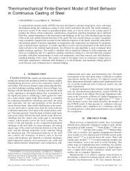
Modeling of Continuous-Casting Defects Related to Mold Fluid Flow
Modeling of Continuous-Casting Defects Related to Mold Fluid Flow
Modeling of Continuous-Casting Defects Related to Mold Fluid Flow

You also want an ePaper? Increase the reach of your titles
YUMPU automatically turns print PDFs into web optimized ePapers that Google loves.
3 rd Internat. Congress on Science & Technology <strong>of</strong> Steelmaking, Charlotte, NC, May 9-12, AIST, Warrendale, PA, 2005, pp. 847-861.<br />
<strong>Modeling</strong> <strong>of</strong> <strong>Continuous</strong>-<strong>Casting</strong> <strong>Defects</strong> <strong>Related</strong> <strong>to</strong> <strong>Mold</strong> <strong>Fluid</strong> <strong>Flow</strong><br />
Brian G. Thomas<br />
Department <strong>of</strong> Mechanical and Industrial Engineering<br />
140 Mech. Engr. Bldg., MC-244, 1206 W. Green St.<br />
Univ. <strong>of</strong> Illinois at Urbana-Champaign<br />
Urbana, IL61801, U.S.A.<br />
Tel: 217-333-6919, Fax: 217-244-6534<br />
bgthomas@uiuc.edu<br />
Keywords: <strong>Continuous</strong> <strong>Casting</strong>, Submerged Entry Nozzle, <strong>Mold</strong> <strong>Flow</strong>, Gas Injection, Air Aspiration, Level Fluctuations, Inclusion<br />
Entrapment, Meniscus Hooks, Surface <strong>Defects</strong>, Slag Entrainment, Computational <strong>Fluid</strong> Dynamics, Models, Solidification<br />
ABSTRACT<br />
The quality <strong>of</strong> continuous-cast steel is greatly influenced by fluid flow in the mold, particularly at the meniscus. Recent examples <strong>of</strong><br />
computational model applications at the University <strong>of</strong> Illinois are presented <strong>to</strong> investigate the formation <strong>of</strong> several different types <strong>of</strong><br />
defects related <strong>to</strong> flow phenomena. The amount <strong>of</strong> gas injection in<strong>to</strong> the tundish nozzle <strong>to</strong> avoid air aspiration is quantified by<br />
modeling. Computational model calculations <strong>of</strong> superheat transport and surface level fluctuations are presented. Meniscus defects,<br />
such as subsurface hooks and their associated inclusions, may form if the superheat contained in the steel is <strong>to</strong>o low, or if <strong>to</strong>p-surface<br />
level fluctuations are <strong>to</strong>o large. A thermal stress model has been used <strong>to</strong> compute the dis<strong>to</strong>rtion <strong>of</strong> the meniscus during a level<br />
fluctuation. Gas bubbles and inclusion particles may enter the mold with the steel flowing through the submerged nozzle. In addition,<br />
mold slag may be entrained from the <strong>to</strong>p surface. These particles may be removed safely in<strong>to</strong> the slag layer, or may become entrapped<br />
in<strong>to</strong> the solidifying shell, <strong>to</strong> form sliver or blister defects in the rolled product. Transient, turbulent flow models have been applied <strong>to</strong><br />
simulate the transport and entrapment <strong>of</strong> particles from both <strong>of</strong> these sources. The insights gained by these modeling efforts aid<br />
greatly in the development <strong>of</strong> processing conditions <strong>to</strong> avoid the formation <strong>of</strong> these defects.<br />
INTRODUCTION<br />
In the continuous casting <strong>of</strong> steel, the task <strong>of</strong> the flow system is <strong>to</strong> transport molten steel at a desired flow rate from the ladle in<strong>to</strong> the<br />
mold cavity and <strong>to</strong> deliver steel <strong>to</strong> the meniscus area that is neither <strong>to</strong>o cold nor <strong>to</strong>o turbulent. In addition, the flow conditions should<br />
minimize exposure <strong>to</strong> air, avoid the entrainment <strong>of</strong> slag or other foreign material, aid in the removal <strong>of</strong> inclusions in<strong>to</strong> the slag layer<br />
and encourage uniform solidification. Achieving these somewhat contradic<strong>to</strong>ry tasks needs careful optimization.<br />
<strong>Fluid</strong> flow in the mold is controlled by many design parameters and operating conditions. Nozzle geometry is the most important, and<br />
includes the bore size, port angle, port opening size, nozzle wall thickness, port shape (round, oval, square), number <strong>of</strong> ports<br />
(bifurcated or multiport), and nozzle bot<strong>to</strong>m design). The flow pattern also depends on parameters which generally cannot be adjusted<br />
<strong>to</strong> accommodate the flow pattern, such as the position <strong>of</strong> the flow control device (slide gate or s<strong>to</strong>pper rod), nozzle clogging, casting<br />
speed, strand width, and strand thickness. Fortunately, other parameters besides nozzle geometry can be adjusted <strong>to</strong> maintain an<br />
optimal flow pattern. These include the injection <strong>of</strong> argon gas, nozzle submergence depth, and the application <strong>of</strong> electromagnetic<br />
forces. In choosing optimal settings for these parameters, it is important <strong>to</strong> understand how they all act <strong>to</strong>gether <strong>to</strong> determine the flow<br />
characteristics. An increase in casting speed, for example, might be compensated by a simultaneous increase in submergence depth<br />
(or electromagnetic force), in order <strong>to</strong> maintain the same surface flow intensity. Thus, all <strong>of</strong> the flow-control parameters must be<br />
optimized <strong>to</strong>gether as a system.<br />
In designing the flow system, it is important <strong>to</strong> consider transients. Sudden changes are the main cause <strong>of</strong> the flow instabilities which<br />
generate surface turbulence and other problems. Because flow parameters are more easily optimized only for steady operation, each<br />
<strong>of</strong> the parameters which affects fluid flow must be carefully controlled. It is especially important <strong>to</strong> keep nearly constant the liquid<br />
steel level in the mold, powder feeding rate (<strong>to</strong> keep a constant liquid slag layer thickness), casting speed, gas injection rate, slide gate
opening, and nozzle position (alignment and submergence). It is also important <strong>to</strong> choose flow conditions which are resistant <strong>to</strong><br />
transients and their detrimental effects, although this is difficult <strong>to</strong> predict.<br />
Many quality problems that originate during the continuous casting <strong>of</strong> steel can be directly attributed <strong>to</strong> poor control <strong>of</strong> fluid flow<br />
conditions in the mold [1] . In order <strong>to</strong> optimize these flow design and operation conditions, it is crucially important <strong>to</strong> understand how<br />
defects arise, and how they are affected by changes in the flow pattern affect those defects. This paper summarizes some <strong>of</strong> these<br />
problems and illustrates the use <strong>of</strong> computational flow models in gaining insight in<strong>to</strong> them, using recent examples developed through<br />
the <strong>Continuous</strong> <strong>Casting</strong> Consortium at the University <strong>of</strong> Illinois.<br />
DEFECTS RELATED TO FLUID FLOW<br />
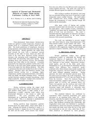
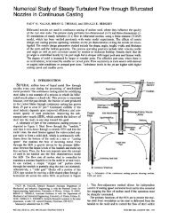
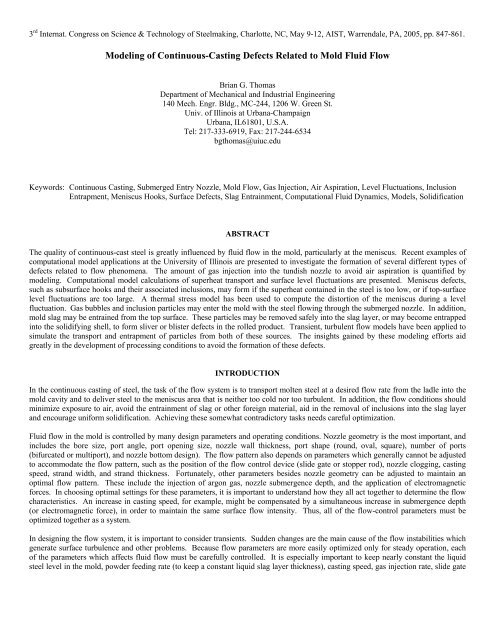
A schematic <strong>of</strong> the continuous casting process is given in Fig. 1,<br />
which illustrates some <strong>of</strong> the phenomena which lead <strong>to</strong> defects<br />
due <strong>to</strong> fluid flow in mold region <strong>of</strong> the process. Jets <strong>of</strong> molten<br />
steel are directed in<strong>to</strong> the liquid by the nozzle ports and traverse<br />
across the mold cavity <strong>to</strong> impinge on the solidifying steel shell<br />
near the narrow faces. Gas bubbles in the jet lower its density,<br />
providing lift which may alter the flow pattern. The jets<br />
impinging against the narrow face may cause shell thinning, and<br />
even breakouts, if the superheat is <strong>to</strong>o high and the interfacial gap<br />
is excessive [2] . The momentum <strong>of</strong> the upward flow along the<br />
narrow faces can raise the meniscus level there, causing a<br />
nonlinear pr<strong>of</strong>ile along the <strong>to</strong>p surface. Where this level is <strong>to</strong>o<br />
high, the infiltration <strong>of</strong> liquid mold flux in<strong>to</strong> the interfacial gap<br />
becomes more difficult, which can lead <strong>to</strong> nonuniform meniscus<br />
heat flux, longitudinal cracks, and other surface defects.<br />
Excessive surface turbulence may cause rapid fluctuations <strong>of</strong> the<br />
surface level. This can disrupt stable solidification at the<br />
meniscus, leading <strong>to</strong> deep oscillation marks, surface depressions,<br />
surface cracks, and local entrapment <strong>of</strong> mold slag leading <strong>to</strong><br />
delamination defects. In addition, high speed flow across the <strong>to</strong>p<br />
surface may shear droplets <strong>of</strong> liquid mold slag in<strong>to</strong> the flow,<br />
where they may become entrained in the liquid steel.<br />
B.G. Thomas, 3 rd Internat. Congress Sci. & Tech. Steelmaking, Charlotte, NC, May 9-12, AIST, Warrendale, PA, 2005, pp. 847-861.<br />
848<br />
copper<br />
mold<br />
Resolidified<br />
Flux<br />
Oscillation<br />
Mark<br />
Contact<br />
Resistances<br />
Air Gap<br />
Nozzle<br />
Nozzle<br />
Support<br />
Roll<br />
Water<br />
Spray<br />
Roll<br />
Flux<br />
Rim<br />
Submerged Entry Nozzle<br />
Flux Powder<br />
Ferrostatic<br />
Pressure<br />
Roll Contact<br />
entrainment<br />
Molten Steel Pool<br />
Solidifying Steel<br />
Shell<br />
Bulging<br />
Liquid Flux<br />
argon<br />
bubbles<br />
jet<br />
nozzle<br />
port<br />
Inclusion<br />
particles and<br />
bubbles<br />
Fig. 1. <strong>Flow</strong> Phenomena in the continuous-casting mold region<br />
On the other hand, if the surface velocities are insufficient, or if the local superheat contained in the molten steel near the meniscus is<br />
<strong>to</strong>o low, then the meniscus may partially freezes <strong>to</strong> form deep oscillation marks and meniscus “hooks”. These hooks are detrimental<br />
because they may entrap particles in<strong>to</strong> the solidifying meniscus. Superheat also affects the nucleation and growth <strong>of</strong> equiaxed grains,<br />
which controls the solidification structure, and defects such as centerline segregation. The transport <strong>of</strong> solute with the fluid is also <strong>of</strong><br />
crucial importance <strong>to</strong> macrosegregation problems, especially <strong>to</strong>wards the final solidification point lower in the strand.<br />
In addition <strong>to</strong> steel and superheat, the jets carry bubbles and inclusion particles in<strong>to</strong> the mold cavity. If the flow pattern enables the<br />
particles <strong>to</strong> reach the <strong>to</strong>p surface, they should be harmlessly removed in<strong>to</strong> the liquid slag layer, so long as the slag is not saturated and<br />
the surface tension forces are not excessive. Alternatively, inclusions and bubbles may become entrapped in<strong>to</strong> the solidifying steel<br />
shell, where they cause slivers, “pencil-pipe” blisters, and other costly defects. Inclusion particle behavior is complicated by their<br />
attachment <strong>to</strong> the surface <strong>of</strong> bubbles, which encourages removal, but also creates potentially-dangerous large clusters, which may also<br />
be created through collisions.<br />
Governing Equations<br />
COMPUTATIONAL MODELING OF FLUID FLOW<br />
Computational models <strong>to</strong> simulate fluid flow phenomena in three dimensions generally start by solving the continuity equation and<br />
Navier-S<strong>to</strong>kes equations for incompressible New<strong>to</strong>nian fluids, which are based on conserving mass (one equation) and momentum<br />
(three equations) at every point in a computational domain. This yields the pressure and velocity components at every point in the<br />
domain. The domain is discretized in<strong>to</strong> small computational cells which should exactly match the true shape <strong>of</strong> the flow region <strong>of</strong> the<br />
process, in this case the nozzle and liquid pool <strong>of</strong> the continuous casting mold and upper strand. When this is performed with a<br />
sufficiently-refined grid <strong>to</strong> directly capture the details <strong>of</strong> the transient fluid flow pattern, this is called “direct numerical simulation”.<br />
Because this generally leads <strong>to</strong> excessive execution times, the computational grid is generally coarsened, and a “subgrid model” is<br />
CL
used <strong>to</strong> account for the effects <strong>of</strong> turbulence which occur at time and length scales smaller than an individual computational volume.<br />
This paper contains many examples using this method, which is called “Large Eddy Simulation” [3, 4] . To achieve even more efficient<br />
computation on coarse grids or meshes, the effects <strong>of</strong> turbulence can be treated as an aritificial increase in the fluid visocisty, which is<br />
determined by solving additional transport equations for the time-averaged flow pattern. The most popular <strong>of</strong> these Reynold’s<br />
Averaged Navier S<strong>to</strong>kes or “RANS” methods is the k-ε turbulence model, which solves two additional transport equations for the<br />
turbulent kinetic energy, k, and its dissipation, ε [5] . The relative advantages and accuracies <strong>of</strong> these approaches for continuous casting<br />
are compared elsewhere [5, 6] .<br />
Unless solidification is modeled <strong>to</strong>gether with the flow, then the shape <strong>of</strong> the liquid domain must be obtained through other means<br />
(such as a heat conduction model <strong>of</strong> shell solidification – CON1D [7] ). In addition, flow through the boundaries <strong>of</strong> this domain must<br />
be imposed <strong>to</strong> satisfy the solidification rate, by specifiying fixed velocity boundary conditions at the walls, as explained elsewhere [3,<br />
8] . When course-grid RANS models are used, the thin boundary layer <strong>of</strong> the liquid is smaller than the computational cells at the walls,<br />
so are taken in<strong>to</strong> account using “turbulent wall functions”, [6] .<br />
To obtain accurate flow solutions, it is <strong>of</strong>ten necessary <strong>to</strong> couple the flow equations <strong>to</strong>gether with simultaneous solution <strong>of</strong> other<br />
equations, in order <strong>to</strong> incorporate other phenomena [9] such as gas injection, or electromagnetic stirring / braking. For example, when<br />
a significant amount <strong>of</strong> gas is injected with the steel, its buoyancy requires a multiphase model. Many different computational<br />
approaches are possible <strong>to</strong> simulate this behavior [9] . Ultimately, it is <strong>of</strong> crucial importance <strong>to</strong> validate the flow model predictions<br />
through comparison with measurements as much as possible, such as PIV measurements in water models [10] .<br />
<strong>Mold</strong> Geometry and <strong>Casting</strong> Conditions Studied<br />
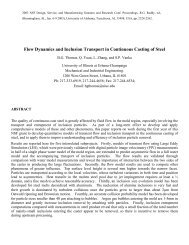
To illustrate the application <strong>of</strong> some <strong>of</strong> these models <strong>to</strong><br />
understand continuous casting defects, examples are taken from<br />
simulations conducted at the University <strong>of</strong> Illinois. For<br />
simplicity, almost all <strong>of</strong> the examples involve the same thin-slab<br />
caster using the domain in Fig. 2. The tapered nozzle has two<br />
15°-down 75x32mm ports and a third round port directed straight<br />
downward, and has 127mm submergence. The straight-walled<br />
mold cavity and upper strand is 132mm thick by 984mm wide,<br />
cast at 1.5m/min with 58 °C <strong>of</strong> superheat, 434 stainless steel and<br />
no gas injection. Further details are given elsewhere on the<br />
casting conditions [11] , computational model equations [3, 12] , and<br />
experimental measurements [11, 12] .<br />
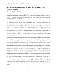
An example <strong>of</strong> the fluid flow velocities in the nozzle and mold<br />
region <strong>of</strong> this thin-slab continuous caster are presented in Fig. 3<br />
[3] . Note the significant asymmetry in the instantaneous flow<br />
pattern in the nozzle, both around the s<strong>to</strong>pper rod, Fig. 3 a) and at<br />
the nozzle ports, Fig. 3 b). <strong>Flow</strong> varies chaotically between sides,<br />
in spite <strong>of</strong> the perfectly symmetrical domain, and long time<br />
operation, reaching a “pseudo-steady” state. This continues in<strong>to</strong><br />
the mold region, as Fig. 3c) shows differences from the time<br />
average, Fig. 3d). Generally, this example is a reasonably-stable<br />
classic double-roll flow pattern. <strong>Flow</strong> impinges on the narrow<br />
faces, splits upward and downward, and traverses the <strong>to</strong>p surface<br />
back <strong>to</strong>wards the SEN.<br />
Portion <strong>of</strong> tundish<br />
S<strong>to</strong>pper rod<br />
934mm<br />
B.G. Thomas, 3 rd Internat. Congress Sci. & Tech. Steelmaking, Charlotte, NC, May 9-12, AIST, Warrendale, PA, 2005, pp. 847-861.<br />
849<br />
SEN<br />
984mm<br />
Turbulent jets<br />
Liquid pool<br />
Narrow face<br />
Wide face<br />
z<br />
x<br />
y<br />
2400mm<br />
80mm<br />
Domain Bot<strong>to</strong>m<br />
132mm<br />
Fig. 2. Schematic <strong>of</strong> the computational domain <strong>of</strong> the thin-slab<br />
steel caster, including tundish nozzle [3] .
-0.85<br />
-0.8<br />
-0.75<br />
z(m)<br />
-0.1 -0.05 0 0.05 0.1x<br />
(m)<br />
(Scale: 1.0m/s)<br />
Fig. 3. Computed flow pattern in the<br />
centerline between wide faces:<br />
a) nozzle (near s<strong>to</strong>pper rod)<br />
b) nozzle (near exit ports)<br />
c) flow in the mold (instantaneous)<br />
d) flow in the mold (time average)<br />
a)<br />
0<br />
0.1<br />
0.2<br />
0.3<br />
0.4<br />
0.5<br />
0.6<br />
0.7<br />
0.8<br />
0.9<br />
1<br />
1.1<br />
1.2<br />
(m)<br />
-0.4 -0.2 0<br />
1.0m/s:<br />
c) d)<br />
MODELING OF PHENOMENA RELATED TO DEFECTS<br />
0.1 0.2 0.3 0.4 (m)<br />
Although it is a challenging task <strong>to</strong> compute, it must be remembered that the average flow pattern itself is <strong>of</strong> no practical interest!<br />
Rather, it is a necessary first step in the simulation <strong>of</strong> related phenomena, which depend on the fluid flow and cause defects in the steel<br />
product. With the tremendous increases in computing power and modeling sophistication, computational models are becoming<br />
increasingly able <strong>to</strong> simulate these important related phenomena.<br />
One important phenomenon is the effect <strong>of</strong> argon gas injection on the pressure distribution, buoyancy, direction, and pattern <strong>of</strong> the<br />
fluid flow, in both the nozzle [13-15] and mold [16, 17] . The transport <strong>of</strong> superheat with the flow [18] , and solidification <strong>of</strong> the steel shell [7,<br />
19] , are important phenomena <strong>to</strong> meniscus hook formation, shell thinning, breakouts, internal microstructure, and macrosegregation.<br />
Solute transport governs intermixing during grade changes [20, 21] and also affects segregation. Inclusion particle transport with the<br />
flow directly controls cleanliness <strong>of</strong> the product [22] . Particles in the flow are subject <strong>to</strong> many forces, especially in the boundary layers<br />
near the solidification front, and at the slag-metal interface [12] , which govern entrapment <strong>of</strong> the particles in<strong>to</strong> the solidification front.<br />
A new entrapment criterion has recently been developed and is presented elsewhere in these proceedings [12] . Other important<br />
phenomena include bulging (for the liquid pool shape changes which affect segregation) and metallurgical thermodynamics (which<br />
affects inclusion precipitation, nozzle clogging, and solidification microstructure). Finally, the model must applied in parametric<br />
studies <strong>to</strong> learn something useful about the real process.<br />
B.G. Thomas, 3 rd Internat. Congress Sci. & Tech. Steelmaking, Charlotte, NC, May 9-12, AIST, Warrendale, PA, 2005, pp. 847-861.<br />
850
AIR ENTRAINMENT DEFECTS<br />
Exposure <strong>to</strong> air at any stage after steel refining leads <strong>to</strong> detrimental oxide inclusions in the steel product. This problem is worst at the<br />
final stage <strong>of</strong> flow in the mold, because there is little opportunity <strong>to</strong> prevent the reoxidation products from becoming entrapped in the<br />
final product as catastrophic large inclusions.<br />
Open stream pouring produces the worst air entrainment problems, which is the reason for submerged entry nozzles and mold flux<br />
operation. Air entrainment is still possible, however, if there are leaks, cracks, inadequate sealing between the nozzle joints or if the<br />
nozzle material becomes porous. If the internal pressure in the nozzle drops below atmospheric pressure, air tends <strong>to</strong> aspirate through<br />
these pathways in<strong>to</strong> the nozzle. This can be identified by nitrogen pickup, and dendritic inclusions from reaction in a high oxygen<br />
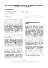
environment. Pressure in the nozzle is lowest just below the flow control device, due <strong>to</strong> the venturi effect <strong>of</strong> the metal stream. For a<br />
given steel flow rate, the pressure drop (and corresponding tundish height) both increase as the opening area is restricted, as shown in<br />
Figs. 4 and 5 for a typical slide gate nozzle [15] . The results in these figures were computed using a 3-D multiphase flow <strong>of</strong> a typical<br />
bifurcated nozzle with 15° downward 78mm square ports [15] . The Eulerian-Eulerian model solves two complete sets <strong>of</strong> mass and<br />
momentum balance equations for the gas and liquid phases, which are fully coupled <strong>to</strong>gether through the phase fractions. The model<br />
was run many times with varying argon injection rate under feasible conditions (ie varying slide gate opening and casting speed<br />
<strong>to</strong>gether appropriately for a given tundish depth).<br />
Air aspiration in<strong>to</strong> the nozzle can be discouraged by proper introduction <strong>of</strong> an inert gas flow, which is one <strong>of</strong> the ways in which argon<br />
gas acts <strong>to</strong> prevent nozzle clogging. Adding argon gas can replace air in feeding leaks around seals. Argon injection also can raise the<br />
minimum pressure in the nozzle above ambient [15] . Note that this occurs because the slide gate must open up <strong>to</strong> accommodate the gas<br />
(shown in the <strong>to</strong>p <strong>of</strong> Fig. 5), in addition <strong>to</strong> the pressurizing effect <strong>of</strong> the gas. The minimum gas flow rate calculated <strong>to</strong> avoid a partial<br />
vacuum is shown in Fig. 5 (bot<strong>to</strong>m). When the slide gate opening is either very small or very large, the pressure never drops below<br />
one atmosphere (zero gage pressure), so gas injection is not needed <strong>to</strong> prevent aspiration. Less gas is needed at low casting speed and<br />
at low tundish level, when the pressure drops are lower. Maintaining a high gas flow rate during these times may disrupt flow in the<br />
mold and thereby be detrimental <strong>to</strong> steel quality.<br />
a) b)<br />
Fig. 4. Pressure drop calculated down nozzle [23]<br />
a) Pressure con<strong>to</strong>urs in centerplane showing that major<br />
variations are in vertical direction<br />
b) Effect <strong>of</strong> slide gate opening on vertical pressure distribution<br />
0<br />
0 0.5 1 1.5 2 2.5<br />
B.G. Thomas, 3 rd Internat. Congress Sci. & Tech. Steelmaking, Charlotte, NC, May 9-12, AIST, Warrendale, PA, 2005, pp. 847-861.<br />
851<br />
L (%)<br />
Corresponding gate opening F<br />
Minimum argon flow rate (SLPM) required<br />
for positive lowest pressure in nozzle<br />
100<br />
80<br />
60<br />
40<br />
20<br />
40<br />
35<br />
30<br />
25<br />
20<br />
Nozzle bore diameter D =78mm<br />
B<br />
Tundish bath depth: H<br />
T<br />
Tundish bath depth: H T<br />
H T =0.6m<br />
H T =0.8m<br />
H T =1.0m<br />
H T =1.2m<br />
H T =1.4m<br />
H T =1.6m<br />
15<br />
10<br />
H =1.0m<br />
T<br />
5<br />
H =0.6m<br />
T<br />
H =0.8m<br />
T<br />
0<br />
0 0.5 1 1.5 2 2.5<br />
<strong>Casting</strong> speed V C (m/min, for 8"x52" slab)<br />
H T =1.6m<br />
H T =1.4m<br />
H T =1.2m<br />
Fig. 5. Optimizing argon gas injection (for a 78-mm bore<br />
nozzle with 90° slide-gate) [23]
SUPERHEAT TRANSPORT, SHELL THINNING, AND BREAKOUTS<br />
Impingement <strong>of</strong> the molten steel jets on<strong>to</strong> the solidifying shell in the mold can cause problems if the jet is either <strong>to</strong>o hot or <strong>to</strong>o cold.<br />
Breakouts occur when the steel shell at mold exit is not strong enough <strong>to</strong> contain the liquid steel and have many causes. One possible<br />
cause is local thin and hot regions <strong>of</strong> the solidifying shell, which can result from high superheat dissipation at the region where an<br />
excessively hot jet impinges on the inside <strong>of</strong> the shell [18, 24] . Problems arise only if this local superheat dissipation is combined with<br />
slow heat extraction from the corresponding shell exterior. This problem is most likely in the <strong>of</strong>f-corner regions, where the jet may<br />
impinge and the shell shrinkage also creates a larger gap.<br />
A computational model <strong>of</strong> superheat transport has been developed for the 132mm thin slab caster in Fig. 2 [6, 25] . This computation is<br />
challenging because the thermal boundary layer has steep gradients, especially in the critical impingement region, which requires a<br />
very fine grid. The temperature con<strong>to</strong>urs presented in Fig. 6 reveal the temperature distribution in various horizontal sections. The jet<br />
leaving the nozzle ports is hottest, and quickly dissipates its superheat and drops in temperature as it moves through the mold.<br />
Measurements <strong>of</strong> temperature from a probe inserted down in<strong>to</strong> the <strong>to</strong>p surface (Fig. 8) agree with the predictions that roughly 70% <strong>of</strong><br />
the superheat is gone at this location, which provides partial validation <strong>of</strong> the model. The predicted temperature fluctuations, indicated<br />
with the error bars, also bracket the variation in the probe measurements. Most (65%) <strong>of</strong> the superheat is dissipated <strong>to</strong> the shell in the<br />
mold (Fig. 7) with most <strong>of</strong> the remainder dissipated just below mold exit [25] . As is common in slab casting with bifurcated nozzles,<br />
the impingement region on the narrow face absorbs the most superheat (12%), and has double the average heat flux per unit area <strong>to</strong> the<br />
wide face. Each wide faces removes 26% <strong>of</strong> the superheat, but its area is over 7X larger. This high-impact region on the narrow face<br />
extends <strong>to</strong> the <strong>of</strong>f-corner region <strong>of</strong> the wide faces. Heat losses through the <strong>to</strong>p slag layer are small.<br />
Figure 9 shows how shell growth depends on the combined effects <strong>of</strong> superheat input from jet impingement and heat removal <strong>to</strong> the<br />
mold walls [26] . Model predictions were made using a comprehensive heat-flow solidification model <strong>of</strong> the mold, interface, and shell,<br />
CON1D, which features momentum, mass, and force (friction) balances on the liquid flux layer [7, 19] . Jet impingement produces a<br />
thinner shell on the narrow face, compared with classic parabolic shell growth on the wide face, as shown in both the computations<br />
and measurements in Fig. 9 [26] . The importance <strong>of</strong> this shell-thinning effect increases with higher casting speeds, higher superheats,<br />
and lower gap heat transfer [18, 24] . Asymmetric flow, such as caused by nozzle clogging may aggravate the effect.<br />
0 0.1<br />
0.2 0.3<br />
0.4<br />
Fig. 6. Temperature distribution in liquid pool<br />
(based on flow conditions in Fig. 3) [25]<br />
-0.05<br />
0<br />
0.050.6<br />
0.7<br />
0.8<br />
0.9<br />
1<br />
1.1<br />
1.2<br />
1.3<br />
Y<br />
Z<br />
T(°C)<br />
1559<br />
1556<br />
1553<br />
1550<br />
1547<br />
1544<br />
1541<br />
1538<br />
1535<br />
1532<br />
1529<br />
1526<br />
1523<br />
1520<br />
1517<br />
1514<br />
1511<br />
1508<br />
1505<br />
1502<br />
X<br />
449KW<br />
B.G. Thomas, 3 rd Internat. Congress Sci. & Tech. Steelmaking, Charlotte, NC, May 9-12, AIST, Warrendale, PA, 2005, pp. 847-861.<br />
852<br />
26%<br />
Y<br />
Z<br />
4%<br />
35%<br />
X<br />
12%<br />
Fig. 7. Superheat removal distribution<br />
(based on temperatures in Fig. 6) [25]
T(°C)<br />
1550<br />
1540<br />
1530<br />
1520<br />
1510<br />
Simulation without SGS model<br />
Simulation with SGS model<br />
Probe insertion<br />
Probe withdrawn<br />
Measurement<br />
position<br />
-20 -10 0 10 20 30 40 50 60 70 80 90 100 110 120 130 140 150 160 170 180<br />
Distance below meniscus (mm)<br />
SEN<br />
Pr<strong>of</strong>ile location<br />
Middle point<br />
Fig. 8. Comparison <strong>of</strong> simulated temperature pr<strong>of</strong>ile and plant<br />
[17, 25]<br />
measurements (#3 – 295mm from CL)<br />
NF<br />
B.G. Thomas, 3 rd Internat. Congress Sci. & Tech. Steelmaking, Charlotte, NC, May 9-12, AIST, Warrendale, PA, 2005, pp. 847-861.<br />
853<br />
Shell Thickness (mm)<br />
30<br />
25<br />
20<br />
15<br />
10<br />
SURFACE DEFECT FORMATION<br />
5<br />
0<br />
Solidifcation Time (s)<br />
0 10 20 30 40 50<br />
Lines: calculated<br />
Symbols: measured<br />
Wide Face<br />
Narrow Face<br />
0 200 400 600 800 1000<br />
Distance below Meniscus (mm)<br />
Fig. 9. Breakout shell thickness pr<strong>of</strong>iles and corresponding<br />
model predictions, showing thin region near location <strong>of</strong><br />
jet impingement on narrow face, relative <strong>to</strong> steady shell<br />
growth down wide face [26] .<br />
Most surface defects in the steel product originate in the mold at the meniscus, where the solidifying steel shell is very thin. The most<br />
obvious source <strong>of</strong> surface defects is the capture <strong>of</strong> foreign particles in<strong>to</strong> the solidifying shell at the meniscus. Particles come from<br />
many sources, including argon bubbles, oxide inclusions generated by prior processes that are carried in with the steel entering the<br />
mold cavity, and slag entrainment. If they are not removed by scale formation or during scarfing, these surface inclusions will lead <strong>to</strong><br />
line defects or “slivers” in the final product. Other problems include deep oscillation marks and surface depressions, which lower the<br />
local heat transfer, leading <strong>to</strong> a hotter local shell temperature, strain concentration, and crack formation. Transverse cracks <strong>of</strong>ten form<br />
during unbending at the root <strong>of</strong> the deep oscillation marks. Longitudinal cracks <strong>of</strong>ten initiate at local hot spots around the meniscus<br />
perimeter. All <strong>of</strong> these defects are worsened by large fluctuations in the <strong>to</strong>p surface liquid level, which depend on the flow pattern in<br />
the mold.<br />
Many surface defects form at the meniscus due <strong>to</strong> variations in the level <strong>of</strong> the liquid steel on the <strong>to</strong>p surface <strong>of</strong> the mold cavity.<br />
These variations take two forms: a relatively steady con<strong>to</strong>ur across the mold width known as a “standing wave”, and “level<br />
fluctuations”, where the local level changes with time. While the standing wave can cause chronic problems with liquid slag feeding,<br />
the time varying level fluctuations cause the most serious surface defects.<br />
Top Surface Level Pr<strong>of</strong>ile<br />
The <strong>to</strong>p-surface level is important because it affects the feeding <strong>of</strong> liquid flux in<strong>to</strong> the interfacial gap between the mold and shell,<br />
which is important <strong>to</strong> heat transfer. Insufficient liquid flux consumption <strong>to</strong> the interfacial gap leads <strong>to</strong> increased thermal resistance,<br />
variable heat transfer, thermal stresses, stress concentration, and ultimately, cracks. A steep surface level pr<strong>of</strong>ile makes it difficult for<br />
complete coverage <strong>of</strong> the liquid flux over the steel surface. If the liquid flux layer becomes so thin that the steel surface <strong>to</strong>uches the<br />
mold powder, it can become contaminated with elements such as carbon, which can cause surface quality problems such as cracks and<br />
segregation in ultra-low carbon steels.<br />
Figure 10 shows a typical instantaneous pr<strong>of</strong>ile <strong>of</strong> the transient <strong>to</strong>p surface level obtained from the flow field in Fig. 3 [3, 27] . This<br />
computation was achieved by performing an balance between kinetic energy and potential energy on the results <strong>of</strong> pressure along the<br />
<strong>to</strong>p surface. The predictions in a water model prediction compared well with measured <strong>to</strong>p surface levels [3] . The results in Fig. 10<br />
also compare with measurements <strong>of</strong> the <strong>to</strong>p surface level in the steel caster, obtained by dipping thin steel sheets. The results match<br />
within the uncertainty in the measurements (error bars), which exists regarding possible rotation <strong>of</strong> the sheets. The level is always<br />
higher near the narrowfaces, by 2mm in the water model and 4-6mm in the steel caster. This is because the steel upward momentum<br />
near the narrowfaces lifts the liquid level there, displacing some <strong>of</strong> the molten flux. The flux layer must be thick enough <strong>to</strong> cover the
steel, in order <strong>to</strong> provide a steady supply <strong>of</strong> molten flux in<strong>to</strong> the interfacial gap <strong>to</strong> lubricate the steel. Thus, the height <strong>of</strong> the surface<br />
“standing wave” is important <strong>to</strong> steel quality.<br />
Steel surface: liquid level pr<strong>of</strong>ile (mm)<br />
10<br />
8<br />
6<br />
4<br />
2<br />
0<br />
-2<br />
-4<br />
-6<br />
SEN<br />
-8<br />
Predicted Level, Right<br />
-10<br />
Predicted Level, Left<br />
-12 Instant t = 20.3 in simulation<br />
Measurement<br />
0 0.1 0.2 0.3 0.4<br />
Distance from center, x (m)<br />
Fig. 10. Comparison <strong>of</strong> predicted and measured <strong>to</strong>p surface liquid levels in steel (Fig. 3 flow field) [3] .<br />
Top Surface Level Fluctuations<br />
Controlled oscillation <strong>of</strong> the mold generates ripples across the liquid level, but does not present an inherent quality problem, because<br />
the liquid near <strong>to</strong> the mold wall tends <strong>to</strong> move with the wall. Large, sudden jumps or dips in liquid level are much more serious.<br />
A sudden jump in local level can cause molten steel <strong>to</strong> overflow the meniscus. In the worst case, the steel can stick <strong>to</strong> the mold wall<br />
and start a sticker breakout. Alternatively, a jump in level can cause an irregular extended frozen meniscus shape, or “hook”. This<br />
defect is discussed in the next section. Variations <strong>of</strong> more than the oscillation stroke over a time interval on the order <strong>of</strong> one second<br />
are the most detrimental. Even low frequency variations (period >60s) may cause defects, if the meniscus overflows and the solid slag<br />
rim is imprinted on the shell or captured [28] .<br />
A sudden severe drop in liquid level exposes the inside <strong>of</strong> the<br />
solidifying shell <strong>to</strong> the mold slag, and also leads <strong>to</strong> surface<br />
depressions. Relaxing the temperature gradient causes cooling<br />
and bending <strong>of</strong> the <strong>to</strong>p <strong>of</strong> the shell <strong>to</strong>ward the liquid steel. When<br />
the liquid level rises back, the solidification <strong>of</strong> new hot solid<br />
against this cool solid surface layer leads <strong>to</strong> even more bending<br />
and stresses when the surface layer reheats [29] . This sequence <strong>of</strong><br />
events is illustrated on a 20mm long section <strong>of</strong> shell in the<br />
thermal-stress model results in Fig. 11, for a 20-30mm level drop<br />
lasting 0.6s [29] . When liquid steel finally overflows the meniscus<br />
<strong>to</strong> continue with ordinary solidification, a surface depression is<br />
left behind, such as shown in Fig. 11.<br />
The microstructural changes and surface depressions associated<br />
with level variations are serious because they initiate other<br />
quality problems in the final product. These problems include<br />
surface cracks and segregation. Surface cracks allow air <strong>to</strong><br />
penetrate beneath the steel surface where it forms iron oxide,<br />
leading <strong>to</strong> line defects in the final product. These defects are<br />
difficult <strong>to</strong> distinguish from inclusion-related defects, other than<br />
by the simpler composition <strong>of</strong> their oxides.<br />
Figure 12 shows the time-variation <strong>of</strong> the horizontal velocity<br />
<strong>to</strong>wards the SEN at the center points between the SEN and the<br />
narrowface on the <strong>to</strong>p surface. This result was obtained from the<br />
transient Large Eddy simulation [3] . The velocity fluctuations are<br />
very large – similar <strong>to</strong> the velocity magnitude. Figure 12 shows a<br />
strong component with high frequency (e.g. flow velocity drops<br />
B.G. Thomas, 3 rd Internat. Congress Sci. & Tech. Steelmaking, Charlotte, NC, May 9-12, AIST, Warrendale, PA, 2005, pp. 847-861.<br />
854
from ~0.4m/s <strong>to</strong>wards the SEN <strong>to</strong> a velocity in the opposite Fig. 11. Events during a severe, level drop (20 mm for 0.6 sec)<br />
direction within 0.2s).<br />
which lead <strong>to</strong> a transverse surface depression [29]<br />
This prediction compares favorably with previous PIV measurements on a 0.4-scale water model [10] . Simulations with and without<br />
flow across the centerline reveal that interaction between the two sides <strong>of</strong> the caster is an important cause <strong>of</strong> the large high frequency<br />
fluctuations. This agrees with findings based on water modeling [30] . These velocity variations are significant, because the level<br />
fluctuations which accompany them are a major cause <strong>of</strong> defects in the process. This is revealed in time-dependent animations <strong>of</strong> the<br />
pr<strong>of</strong>ile in Fig. 10 [3] .<br />
Horizontal velocity <strong>to</strong>wards SEN (m/s)<br />
0.5<br />
0.4<br />
0.3<br />
0.2<br />
0.1<br />
0<br />
reverse flow <strong>to</strong>wards narrow faces<br />
20 25 30 35 Time (s)<br />
40 45<br />
Fig. 12. Time variations <strong>of</strong> the horizontal velocity <strong>to</strong>wards SEN at the center point <strong>of</strong> the <strong>to</strong>p surface <strong>of</strong> steel (see Figs. 2 and 3)<br />
Surface Hook formation<br />
Subsurface hook formation at the meniscus during the continuous casting <strong>of</strong> steel slabs is an important cause <strong>of</strong> surface defects, owing<br />
<strong>to</strong> their easy entrapment <strong>of</strong> mold flux and inclusion-laden gas bubbles. Figure 14 shows a typical hook, which is usually associated<br />
with an oscillation mark and especially plagues ultra-low carbon steels [31, 32] . Their formation mechanism is not completely<br />
unders<strong>to</strong>od, owing <strong>to</strong> the complexity <strong>of</strong> phenomena at the meniscus, and the difficulty <strong>of</strong> obtaining good measurements. They are<br />
known, however, <strong>to</strong> be affected by steel grade, superheat, level fluctuations, and oscillation conditions [31, 32] .<br />
The effect <strong>of</strong> superheat is investigated by close examination <strong>of</strong> the superheat results, shown in Fig. 6 [25] , and further application <strong>of</strong><br />
computational models <strong>to</strong> the meniscus region. As the steel flows through the mold cavity, it continuously drops in temperature. The<br />
coldest liquid is found at the meniscus, around the perimeter <strong>of</strong> the <strong>to</strong>p surface, especially near the narrow face and the wideface<br />
centerline near the inlet nozzle. The fluid is coldest here because it is both far from the inlet and stagnant. In extreme cases, these<br />
regions are subject <strong>to</strong> meniscus freezing, skull formation, and even “bridging”, where steel or slag freezes across the shortest distance<br />
between the nozzle and meniscus <strong>of</strong> the wide face, <strong>of</strong>ten leading <strong>to</strong> a breakout.<br />
The heat flux corresponding <strong>to</strong> superheat delivery <strong>to</strong> the solidifying steel shell in the critical meniscus region is shown in Fig. 13 (for<br />
slightly different casting conditions chosen <strong>to</strong> match the hook in Fig. 14 [33] ). The lowest superheat flux is found at the corner and<br />
near the nozzle, which coincides with the locations where the deepest meniscus hooks are observed in practice. Hooks also tend <strong>to</strong> be<br />
deeper on wide slabs with low superheat and low casting speed, for the same reasons.<br />
Using a best estimate for superheat flux at the meniscus, the solidification <strong>of</strong> the initial shell was computed with CON1D, and the<br />
thickness compared with the measured hook shell thickness in Fig. 14 [32] . For the calculation, the meniscus location where the hook<br />
shell starts is taken at one theoretical oscillation mark pitch above the measured deepest part <strong>of</strong> the oscillation mark at the hook. This<br />
suggests that the etched hook shape was created by a change in heat flow conditions that occurred due <strong>to</strong> metal overflow <strong>of</strong> the initial<br />
shell at the meniscus at the instant that the oscillation mark formed. The predicted shell pr<strong>of</strong>ile roughly matches the measured pr<strong>of</strong>ile.<br />
The results suggest that the <strong>to</strong>p <strong>of</strong> the actual hook shell was truncated, likely due <strong>to</strong> breaking-<strong>of</strong>f or melting during the liquid overflow<br />
event. Further computational efforts are currently being conducted <strong>to</strong> investigate the fundamental formation mechanism <strong>of</strong> these<br />
hooks.<br />
B.G. Thomas, 3 rd Internat. Congress Sci. & Tech. Steelmaking, Charlotte, NC, May 9-12, AIST, Warrendale, PA, 2005, pp. 847-861.<br />
855<br />
Left<br />
Right
Distance below meniscus (m)<br />
0 50 100 150 200<br />
0.00<br />
0.02<br />
0.04<br />
0.06<br />
0.08<br />
0.10<br />
SuperHeat flux (kW/m 2 )<br />
wide face center<br />
1/4 wide face<br />
corner<br />
narrow center<br />
Upper OM<br />
pitch<br />
Fig. 13 Variation <strong>of</strong> superheat flux in meniscus<br />
region around strand perimeter [33]<br />
Hook shell<br />
thickness<br />
OM valley<br />
Melting?<br />
1mm<br />
0.0<br />
0 1 2 3 4 5 6 7 8 9 10<br />
B.G. Thomas, 3 rd Internat. Congress Sci. & Tech. Steelmaking, Charlotte, NC, May 9-12, AIST, Warrendale, PA, 2005, pp. 847-861.<br />
856<br />
Hook thickness (mm)<br />
1.2<br />
1.0<br />
0.8<br />
0.6<br />
0.4<br />
0.2<br />
CON1D prediction<br />
Measured data<br />
Theoretical OM pitch<br />
Upper OM width<br />
Distance below meniscus (mm)<br />
Fig. 14. Typical hook shape (left) and comparison <strong>of</strong> hook-shell thickness with<br />
shell thickness prediction from CON1D [32]<br />
INCLUSION PARTICLE ENTRAPMENT<br />
The entrapment <strong>of</strong> inclusions, bubbles, slag, and other particles during solidification <strong>of</strong> steel products is a critically-important quality<br />
concern. They require expensive inspection, surface grinding and even rejection <strong>of</strong> the final product. Furthermore, if undetected,<br />
large particles lower the fatigue life, while captured bubbles and inclusion clusters cause slivers, blisters, and other surface defects in<br />
rolled products. These particles have two main sources: bubbles and inclusions generated during upstream processing which enter the<br />
mold through the submerged entry nozzle, and the entrainment <strong>of</strong> mold slag from the <strong>to</strong>p surface, discussed in the next section.<br />
t=1.62s<br />
d p =100μm<br />
t=3.60s<br />
d p =100μm<br />
t=18.0s<br />
d p =100μm<br />
Fig.15. Transport <strong>of</strong> 100 μm inclusions in strand at different times<br />
(red = final entrapment location, based on flow pattern in Fig. 3) [4]<br />
Particles leaving the tundish can either stick <strong>to</strong> the<br />
nozzle walls, where they lead <strong>to</strong> clogging, travel with<br />
the recirculating flow <strong>to</strong> be safely removed in<strong>to</strong> the<br />
mold slag at the <strong>to</strong>p surface, or become entrapped in<strong>to</strong><br />
the solidifying shell, where they lead <strong>to</strong> product<br />
defects. The fraction <strong>of</strong> particles going <strong>to</strong> each <strong>of</strong> these<br />
destinations is being quantified using a new<br />
computational model. This model first calculates the<br />
transient turbulent flow field in the mold region using<br />
Large Eddy Simulation (LES), with a sub-grid-scale<br />
(SGS) k model [3] . Next, the transport and capture <strong>of</strong><br />
many individual particles are simulated using a<br />
Lagrangian approach <strong>to</strong> track the trajec<strong>to</strong>ries [4] . The<br />
results presented here are for 30,000 particles, in order<br />
<strong>to</strong> achieve reasonable statistics. The transport equation<br />
includes the effects <strong>of</strong> six hydrodynamic forces: drag,<br />
shear-lift, pressure-gradient, stress-gradient, addedmass,<br />
Basset his<strong>to</strong>ry, and buoyancy. The model<br />
features a new criterion <strong>to</strong> determine particle<br />
entrapment, which considers the effects <strong>of</strong> four more<br />
forces which are important in the fluid boundary layer<br />
adjacent <strong>to</strong> the solidification front. Further details on<br />
the model are given in the other paper [12] and<br />
elsewhere [8] .<br />
Instantaneous snapshots <strong>of</strong> the trajec<strong>to</strong>ries <strong>of</strong> 100 μm<br />
alumina inclusion particles at different times after<br />
entering in the mold region are shown in Fig. 15, based<br />
on the flow pattern in Fig. 3.
Note that the domain includes the 1.11m submerged entry nozzle and the <strong>to</strong>p 2.40m <strong>of</strong> the steel strand. Particles which <strong>to</strong>uch the <strong>to</strong>p<br />
surface are assumed <strong>to</strong> be removed in<strong>to</strong> the slag layer (and are then colored red). Note that significant asymmetry exists in the flow,<br />
which directly affects the particles, especially in the lower regions <strong>of</strong> the strand. Many more particles leave from the right side <strong>of</strong> the<br />
domain, although investigation revealed that there was no significant asymmetry at the nozzle port exit. This behavior is attributed<br />
solely <strong>to</strong> the chaotic nature <strong>of</strong> turbulence.<br />
Nozzle Entrapment (Clogging)<br />
The inclusion trajec<strong>to</strong>ries themselves are <strong>of</strong> much less practical interest than their<br />
final entrapment locations. Inclusions attaching <strong>to</strong> the nozzle walls contribute <strong>to</strong><br />
clogging, which is detrimental <strong>to</strong> steel quality in several ways: the clogging slows<br />
production; large clogs can suddenly break <strong>of</strong>f and enter the mold; and the flow<br />
pattern becomes unstable [15] .<br />
An example <strong>of</strong> the predicted locations <strong>of</strong> inclusions <strong>to</strong>uching the nozzle walls are<br />
shown in Fig. 16. About 10% <strong>of</strong> the particles exiting the tundish <strong>to</strong>uched the<br />
s<strong>to</strong>pper rod, and a further 16% <strong>to</strong>uched an inner wall <strong>of</strong> the nozzle [8] . These<br />
inclusions might stick <strong>to</strong> cause nozzle clogging in a real caster, depending on the<br />
properties <strong>of</strong> the nozzle material and thermodynamic reactions at the interface.<br />
Note that the bot<strong>to</strong>m portion <strong>of</strong> the s<strong>to</strong>pper rod and nearby walls <strong>of</strong> the upper<br />
nozzle have the most inclusion entrapment, which agrees with plant experience.<br />
Some particles <strong>to</strong>uched the bot<strong>to</strong>m <strong>of</strong> the SEN near the outlet ports.<br />
Strand Entrapment (Sliver <strong>Defects</strong> and Blisters)<br />
Particles traveling in the liquid pool may become entrapped in<strong>to</strong> the solidifying<br />
shell <strong>to</strong> form defects. In the new entrapment criterion, particles <strong>to</strong>uching the<br />
solidification front were assumed always <strong>to</strong> become entrapped if they are smaller<br />
than the primary dendrite arm spacing. Larger particles are subjected <strong>to</strong> a force<br />
balance which considers the effects <strong>of</strong> transverse fluid flow on washing the<br />
particles away from the interface, the angle <strong>of</strong> the reaction forces between the<br />
dendrite tips, and the other hydrodynamic forces. In addition, this force balance<br />
includes the effects <strong>of</strong> the surface tension gradient, such as caused by sulfur<br />
rejection at the solidification front, the lubrication force, and Van-der-Waals<br />
forces. All three <strong>of</strong> these forces tend <strong>to</strong> encourage particle entrapment, and<br />
should be explored in further work. Further details on the entrapment criterion<br />
are given in the other paper [12] .<br />
Fig. 16 Final Entrapment location <strong>of</strong> inclusions<br />
on s<strong>to</strong>pper rod and nozzle walls (flow conditions<br />
in Fig. 3)<br />
Inclusion entrapment locations in the final solidified strand were computed from the trajec<strong>to</strong>ry results, shown in Fig. 15, and are<br />
presented in Fig. 17. Over 84% <strong>of</strong> the 100 μm inclusions were captured in the shell, including 51% in the upper 2.4m <strong>of</strong> the strand.<br />
Only 8% <strong>to</strong>uched the <strong>to</strong>p slag surface, while the remaining 8% <strong>to</strong>uched the outside <strong>of</strong> the nozzle refrac<strong>to</strong>ry walls and might be<br />
removed. After injecting larger 400 μm inclusions, only 30% were entrapped in the solidified shell. This is due both <strong>to</strong> their<br />
increased chances <strong>of</strong> flotation from their higher buoyancy, and <strong>to</strong> their smaller likelihood <strong>of</strong> capture in<strong>to</strong> the solidification front.<br />
The particles were injected through the nozzle ports during a 9s time period, which corresponds <strong>to</strong> 0.23m <strong>of</strong> travel <strong>of</strong> the meniscus<br />
down with the strand, and is labeled on Fig. 17. The entrapment locations in the strand are distributed both upstream and downstream<br />
about this location. The side and <strong>to</strong>p views, Figs. 17 a) and b), show that the captured particles concentrate in a thin band around the<br />
strand perimeter, and especially near the narrow faces. There does not appear <strong>to</strong> be any significant concentration <strong>of</strong> particles<br />
associated with flow from the central port. Fig. 17d) reveals strong asymmetry in the particle trajec<strong>to</strong>ries through the liquid, as many<br />
more particles exit the left side <strong>of</strong> the domain in<strong>to</strong> the lower strand. However, this asymmetry appears <strong>to</strong> be greatly diminished in the<br />
final entrapment locations, as Fig. 17c) shows much less bias <strong>to</strong>wards the left side. This is because faster moving flow across the<br />
solidification front makes capture more difficult. Capture is most likely along those regions <strong>of</strong> flow along the solidification front<br />
which move slowly downward near the casting speed. It is important <strong>to</strong> emphasize that the asymmetry is chaotic and although the<br />
stronger flow <strong>to</strong> the left persisted for a long time interval, (>30s), it could change <strong>to</strong> the opposite side at any time.<br />
By reprocessing the results <strong>to</strong> model continuous inclusion injection, it is possible <strong>to</strong> compute the expected distribution <strong>of</strong> <strong>to</strong>tal oxygen<br />
content in an average section through the final solid strand [4] . Figure 18 presents the results for 10 ppm <strong>to</strong>tal oxygen content entering<br />
from the nozzle ports in the form <strong>of</strong> 100 μm particles. Figure 18 shows that the entrapment is concentrated from 10-25mm beneath<br />
the strand surface at the centerline. Considering the shell thickness pr<strong>of</strong>ile down the strand, this region corresponds <strong>to</strong> a capture<br />
B.G. Thomas, 3 rd Internat. Congress Sci. & Tech. Steelmaking, Charlotte, NC, May 9-12, AIST, Warrendale, PA, 2005, pp. 847-861.<br />
857
egion <strong>of</strong> ~0.5-2.5 m below the meniscus. Local spikes in <strong>to</strong>tal oxygen in this band depend on sample size, but are predicted <strong>to</strong><br />
exceed 60ppm, owing <strong>to</strong> grouping <strong>to</strong>gether <strong>of</strong> captured particles simply due <strong>to</strong> chaotic turbulence. The final entrapment position in<br />
the lower strand is uncertain, so this region is represented as a dashed line. Its average oxygen content is 6ppm, indicating that<br />
relatively fewer particles penetrate deeper than 2.5m below the meniscus in<strong>to</strong> the lower regions <strong>of</strong> the strand.<br />
The caster simulated here has straight vertical walls. In a curved caster, large particles in the lower recirculation zone tend <strong>to</strong> spiral<br />
<strong>to</strong>wards the inner radius, with increased entrapment rates. Entrapped solid oxide particles eventually lead <strong>to</strong> surface slivers or internal<br />
defects, which act as stress concentration sites <strong>to</strong> reduce fatigue and <strong>to</strong>ughness properties <strong>of</strong> the final product. Gas bubbles captured in<br />
this way eventually may cause blister defects such as “pencil pipe” which appear as streaks in the final rolled product. When the slab<br />
is rolled, the subsurface bubbles elongate and the layer <strong>of</strong> metal separating them from the surface becomes thinner. Later during<br />
annealing, they can expand <strong>to</strong> raise the surface <strong>of</strong> the sheet locally, especially if the steel is weak such as ultra-low carbon grades, or if<br />
hydrogen is present [34] . Further computations are needed <strong>to</strong> quantify the expected benefits <strong>of</strong> lowering the casting speed, or using a<br />
vertical mold and upper strand.<br />
These results suggest that most <strong>of</strong> inclusions which enter the mold become entrapped in the final product. Thus, nozzle design and<br />
mold operation should focus on controlling flow at the meniscus <strong>to</strong> avoid the further entrainment <strong>of</strong> new inclusions, rather than<br />
altering the flow pattern <strong>to</strong> encourage the removal <strong>of</strong> inclusions entering the mold. Upstream operations should focus on inclusion<br />
removal and reoxidation prevention.<br />
a)<br />
z(m)<br />
y(m)<br />
-3<br />
-2<br />
-1<br />
0<br />
1<br />
x(m)<br />
-0.5 0 0.5<br />
wide face view<br />
100μm particles<br />
9s <strong>of</strong> particle injection<br />
meniscus location<br />
at first particle injection<br />
b)<br />
y(m)<br />
-0.5 0 0.5<br />
z(m)<br />
-3<br />
-2<br />
-1<br />
0<br />
1<br />
100μm particles<br />
9s <strong>of</strong> particle injection<br />
meniscus location<br />
at first particle injection<br />
narrow face view<br />
-0.05<br />
c)<br />
-0.4 -0.3 -0.2 -0.1 0<br />
x (m)<br />
0.1 0.2 0.3 0.4<br />
y(m)<br />
0.05<br />
0<br />
0.05<br />
0<br />
100μm particles<br />
-0.05<br />
d)<br />
-0.4 -0.3 -0.2 -0.1 0<br />
x (m)<br />
0.1 0.2 0.3 0.4<br />
100<br />
90<br />
80<br />
70<br />
60<br />
50<br />
40<br />
30<br />
20<br />
10<br />
Wide Face<br />
Wide Face<br />
0<br />
-0.06 -0.04 -0.02 0 0.02 0.04 0.06<br />
y distance along slab thickness direction (m)<br />
B.G. Thomas, 3 rd Internat. Congress Sci. & Tech. Steelmaking, Charlotte, NC, May 9-12, AIST, Warrendale, PA, 2005, pp. 847-861.<br />
858<br />
Oxygen content (ppm)<br />
Fig. 18 Oxygen content along the slab<br />
centerlines (100 μm inclusions).<br />
<strong>to</strong>p view<br />
Fig. 17. Particle entrapment locations predicted in the final solidified strand (based on trajec<strong>to</strong>ries in Fig. 15)<br />
<strong>to</strong>p view (at time <strong>of</strong> exit from domain)
MOLD SLAG ENTRAINMENT<br />
<strong>Mold</strong> slag can be entrained in<strong>to</strong> the solidifiying shell due <strong>to</strong> vortexing, high velocity flow that shears slag from the surface, and<br />
turbulence at the meniscus. The capture <strong>of</strong> large inclusions in<strong>to</strong> the solidifying shell then leads <strong>to</strong> obvious line defects or “slivers” in<br />
the final product.<br />
Vortexing most <strong>of</strong>ten occurs during conditions <strong>of</strong> asymmetrical flow, where steel flows rapidly through the narrow passage between<br />
the SEN and the mold. This creates swirling just beside the SEN, as shown in Fig. 19 [25] . This swirl or vortex may draw mold slag<br />
downward, near the sides <strong>of</strong> the nozzle. If it is then entrained with the jets exiting the nozzle ports, this slag will be dispersed<br />
everywhere and create defects as discussed in in the previous section. In addition <strong>to</strong> drawing in slag, the vortex is detrimental because<br />
it hastens erosion <strong>of</strong> the nozzle refrac<strong>to</strong>ry walls. Visible erosion patterns at the locations near the <strong>of</strong>f-corner and center <strong>of</strong> the wide<br />
thin-slab nozzle have been observed in practice. In addition <strong>to</strong> the vortex, slag may also be drawn downward by the recirculation<br />
pattern which accompanies flow from the nozzle ports. Thus, slag entrainment is most likely with shallow nozzle submergence and<br />
high casting speed.<br />
y<br />
0.05<br />
0<br />
-0.05<br />
SEN<br />
0 0.1 0.2 x 0.3 0.4<br />
Fig. 19 Velocity streamlines showing vortexing near SEN (in-plane 38.5 mm below <strong>to</strong>p surface, flow conditions in Fig. 3) [25]<br />
The entrainment <strong>of</strong> mold slag also occurs when the velocity<br />
across the <strong>to</strong>p surface becomes high enough <strong>to</strong> shear mold slag<br />
fingers down in<strong>to</strong> the flow, where they can be entrained. Figure<br />
20 illustrates this mechanism [12] . Once it has broken up in<strong>to</strong><br />
particles and been dispersed in<strong>to</strong> the flow, the slag particles<br />
behave the same as inclusions that have entered through the<br />
nozzle. Many <strong>of</strong> these slag particles float quickly back in<strong>to</strong> the<br />
slag layer, owing <strong>to</strong> their large buoyancy. However, many<br />
become entrapped as internal inclusion defects. Entrainment is<br />
easier for deeper slag layers, lower slag viscosity, and lower slag<br />
surface tension [35] . To avoid shearing slag in this manner, the <strong>to</strong>p<br />
surface velocity must be kept below a critical maximum value,<br />
suggested <strong>to</strong> be 0.3 m/s or 0.4 m/s [36] . The critical velocity may<br />
also be exceeded when the standing wave becomes <strong>to</strong>o severe and<br />
the interface emulsifies [37] . The critical velocity also depends on<br />
the relative densities <strong>of</strong> the steel and flux phases and the mold<br />
geometry [37] .<br />
High velocity surface flows also may cause emulsification <strong>of</strong> the<br />
slag, where slag and steel intermix and even create a foam, if <strong>to</strong>o<br />
much argon gas is present [38] . This allows easy capture <strong>of</strong><br />
particles via vortexing or surface shearing flow. Meniscus<br />
turbulence related <strong>to</strong> level variations is another mechanism for<br />
slag entrainment, as discussed previously.<br />
t = 2.88s<br />
d p =100μm<br />
Fig. 20. Instantaneous snapshot <strong>of</strong> the distribution <strong>of</strong> 100 μm<br />
slag particles, just after entrainment in<strong>to</strong> the <strong>to</strong>p surface (red<br />
indicates particles that refloated, while blue indicates particles<br />
that are still moving, flow conditions in Fig. 3)<br />
B.G. Thomas, 3 rd Internat. Congress Sci. & Tech. Steelmaking, Charlotte, NC, May 9-12, AIST, Warrendale, PA, 2005, pp. 847-861.<br />
859
CONCLUSIONS<br />
<strong>Fluid</strong> flow in the continuous casting process can generate many different types <strong>of</strong> defects in the final product. Computational models<br />
<strong>of</strong> fluid flow coupled with other important phenomena can be useful <strong>to</strong>ols <strong>to</strong> study and quantify these problems. Several different<br />
examples <strong>of</strong> insights in<strong>to</strong> defects are presented here, based on simulations conducted at the University <strong>of</strong> Illinois. These include air<br />
aspiration in<strong>to</strong> the nozzle, shell thinning and breakouts from excessive superheat, surface defects from a steep “standing wave”, level<br />
fluctuations, subsurface hook formation and the associated deep oscillation marks and particle entrapment, and the entrapment in<strong>to</strong> the<br />
solidifying shell <strong>of</strong> inclusion particles and bubbles entering the nozzle or from mold slag entrainment at the <strong>to</strong>p surface.<br />
ACKNOWLEDGMENTS<br />
The author wishes <strong>to</strong> thank his former students, especially Q. Yuan, B. Zhao, and H. Shin, and Research Scientist L. Zhang for their<br />
efforts generating the results which are sampled in this paper. This work was supported by the National Science Foundation (Grant #<br />
DMI-01-15486) and the <strong>Continuous</strong> <strong>Casting</strong> Consortium at the University <strong>of</strong> Illinois. Thanks are also given <strong>to</strong> the National Center for<br />
Supercomputing Applications at the University <strong>of</strong> Illinois for computing time.<br />
REFERENCES<br />
1. B.G. Thomas, "Chapter 14. <strong>Fluid</strong> <strong>Flow</strong> in the <strong>Mold</strong>," in Making, Shaping and Treating <strong>of</strong> Steel: <strong>Continuous</strong> <strong>Casting</strong>, Vol. 5, A.<br />
Cramb, ed. AISE Steel Foundation, Pittsburgh, PA, 2003, 14.1-14.41.<br />
2. B.G. Thomas, A. Moitra and R. McDavid, "Simulation <strong>of</strong> Longitudinal Off-Corner Depressions in <strong>Continuous</strong>ly-Cast Steel<br />
Slabs," ISS Transactions, Vol. 23 (4), 1996, 57-70.<br />
3. Q. Yuan, B.G. Thomas and S.P. Vanka, "Study <strong>of</strong> Transient <strong>Flow</strong> and Particle Transport during <strong>Continuous</strong> <strong>Casting</strong> <strong>of</strong> Steel<br />
Slabs, Part 1. <strong>Fluid</strong> <strong>Flow</strong>," Metal. & Material Trans. B., Vol. 35B (4), 2004, 685-702.<br />
4. Q. Yuan, B.G. Thomas and S.P. Vanka, "Study <strong>of</strong> Transient <strong>Flow</strong> and Particle Transport during <strong>Continuous</strong> <strong>Casting</strong> <strong>of</strong> Steel<br />
Slabs, Part 2. Particle Transport.," Metal. & Material Trans. B., Vol. 35B (4), 2004, 703-714.<br />
5. B.G. Thomas, Q. Yuan, S. Sivaramakrishnan, T. Shi, S.P. Vanka, M.B. Assar, "Comparison <strong>of</strong> Four Methods <strong>to</strong> Evaluate <strong>Fluid</strong><br />
Velocities in a <strong>Continuous</strong> <strong>Casting</strong> <strong>Mold</strong>," ISIJ Internat., Vol. 41 (10), 2001, 1266-1276.<br />
6. Q. Yuan, B. Zhao, S.P. Vanka, B.G. Thomas, "Study <strong>of</strong> Computational Issues in Simulation <strong>of</strong> Transient <strong>Flow</strong> in <strong>Continuous</strong><br />
<strong>Casting</strong>," Steel Research International, Vol. 76 (1), 2005, 33-43.<br />
7. Y. Meng and B.G. Thomas, "Heat Transfer and Solidification Model <strong>of</strong> <strong>Continuous</strong> Slab <strong>Casting</strong>: CON1D," Metal. & Material<br />
Trans., Vol. 34B (5), 2003, 685-705.<br />
8. Q. Yuan, "Transient Study <strong>of</strong> Turbulent <strong>Flow</strong> and Particle Transport During <strong>Continuous</strong> <strong>Casting</strong> <strong>of</strong> Steel Slabs," PhD Thesis,<br />
University <strong>of</strong> Illinois at Urbana-Champaign, IL, 2004.<br />
9. B.G. Thomas and L. Zhang, "Review: Mathematical <strong>Modeling</strong> <strong>of</strong> <strong>Fluid</strong> <strong>Flow</strong> in <strong>Continuous</strong> <strong>Casting</strong>," ISIJ Internat., Vol. 41<br />
(10), 2001, 1181-1193.<br />
10. Q. Yuan, S. Sivaramakrishnan, S.P. Vanka, B.G. Thomas, "Computational and Experimental Study <strong>of</strong> Turbulent <strong>Flow</strong> in a 0.4-<br />
Scale Water Model <strong>of</strong> a <strong>Continuous</strong> Steel Caster," Metall. & Mater. Trans., Vol. 35B (5), 2004, 967-982.<br />
11. B.G. Thomas, R.J. O'Malley and D.T. S<strong>to</strong>ne, "Measurement <strong>of</strong> temperature, solidification, and microstructure in a continuous<br />
cast thin slab," <strong>Modeling</strong> <strong>of</strong> <strong>Casting</strong>, Welding, and Advanced Solidification Processes, (San Diego, CA), TMS, Warrendale,<br />
PA, Vol. VIII, 1998, 1185-1199.<br />
12. Q. Yuan and B.G. Thomas, "Transport and Entrapment <strong>of</strong> Particles in <strong>Continuous</strong> <strong>Casting</strong> <strong>of</strong> Steel," 3rd International Congress<br />
on Science and Technology <strong>of</strong> Steelmaking, (Charlotte, NC, May 9-12, 2005), 2005.<br />
13. H. Bai and B.G. Thomas, "Turbulent <strong>Flow</strong> <strong>of</strong> Liquid Steel and Argon Bubbles in Slide-Gate Tundish Nozzles, Part I, Model<br />
Development and Validation," Metall. Mater. Trans. B, Vol. 32B (2), 2001, 253-267.<br />
14. H. Bai and B.G. Thomas, "Turbulent <strong>Flow</strong> <strong>of</strong> Liquid Steel and Argon Bubbles in Slide-Gate Tundish Nozzles, Part II, Effect <strong>of</strong><br />
Operation Conditions and Nozzle Design," Metall. Mater. Trans. B, Vol. 32B (2), 2001, 269-284.<br />
15. H. Bai and B.G. Thomas, "Effects <strong>of</strong> Clogging, Argon Injection and <strong>Continuous</strong> <strong>Casting</strong> Conditions on <strong>Flow</strong> and Air<br />
Aspiration in Submerged Entry Nozzles," Metall. Mater. Trans. B, Vol. 32B (4), 2001, 707-722.<br />
16. B.G. Thomas, X. Huang and R.C. Sussman, "Simulation <strong>of</strong> Argon Gas <strong>Flow</strong> Effects in a <strong>Continuous</strong> Slab Caster," Metall.<br />
Trans. B, Vol. 25B (4), 1994, 527-547.<br />
17. T. Shi, "Effect <strong>of</strong> argon injection on fluid flow and heat transfer in the continuous slab casting mold," MS Thesis, University <strong>of</strong><br />
Illinois at Urbana-Champaign, 2001.<br />
18. X. Huang, B.G. Thomas and F.M. Najjar, "<strong>Modeling</strong> Superheat Removal during <strong>Continuous</strong> <strong>Casting</strong> <strong>of</strong> Steel Slabs," Metall.<br />
Trans. B, Vol. 23B (6), 1992, 339-356.<br />
19. Y. Meng and B.G. Thomas, "Interfacial Friction-<strong>Related</strong> Phenomena in <strong>Continuous</strong> <strong>Casting</strong> with <strong>Mold</strong> Slags," Metall. &<br />
Materials Trans. B, Vol. 34B (5), 2003, 707-725.<br />
B.G. Thomas, 3 rd Internat. Congress Sci. & Tech. Steelmaking, Charlotte, NC, May 9-12, AIST, Warrendale, PA, 2005, pp. 847-861.<br />
860
20. X. Huang and B.G. Thomas, "Intermixing Model <strong>of</strong> <strong>Continuous</strong> <strong>Casting</strong> During a Grade Transition," Metall. Trans. B, Vol.<br />
27B (4), 1996, 617-632.<br />
21. B.G. Thomas, "<strong>Modeling</strong> Study <strong>of</strong> Intermixing in Tundish and Strand during a <strong>Continuous</strong>-<strong>Casting</strong> Grade Transition," Iron and<br />
Steelmaker, Vol. 24 (12), 1997, 83-96.<br />
22. R.C. Sussman, M. Burns, X. Huang, B.G. Thomas, "Inclusion Particle Behavior in a <strong>Continuous</strong> Slab <strong>Casting</strong> <strong>Mold</strong>," Iron &<br />
Steelmaker, Vol. 20 (2), 1993, 14-16.<br />
23. H. Bai, "Argon Bubble Behavior in Slide-Gate Tundish Nozzles During <strong>Continuous</strong> <strong>Casting</strong> <strong>of</strong> Steel Slabs," PhD Thesis,<br />
University <strong>of</strong> Illinois at Urbana-Champaign, 2000.<br />
24. G.D. Lawson, S.C. Sander, W.H. Emling, A. Moitra, B.G. Thomas, "Prevention <strong>of</strong> Shell Thinning Breakouts Associated with<br />
Widening Width Changes," in Steelmaking Conf. Proc., Vol. 77, ISS, Warrendale, PA, (Chicago, IL), 1994, 329-336.<br />
25. B. Zhao, "Numerical Study <strong>of</strong> Heat Transfer in <strong>Continuous</strong> <strong>Casting</strong> <strong>of</strong> Steel," MS Thesis, University <strong>of</strong> Illinois at Urbana-<br />
Champaign, 2003.<br />
26. B.G. Thomas, R. O'Malley, T. Shi, Y. Meng, D. Creech, D. S<strong>to</strong>ne, "Validation <strong>of</strong> <strong>Fluid</strong> <strong>Flow</strong> and Solidification Simulation <strong>of</strong> a<br />
<strong>Continuous</strong> Thin Slab Caster," in <strong>Modeling</strong> <strong>of</strong> <strong>Casting</strong>, Welding, and Advanced Solidification Processes, Vol. IX, Shaker<br />
Verlag GmbH, Aachen, Germany, (Aachen, Germany, August 20-25, 2000), 2000, 769-776.<br />
27. Q. Yuan, B.G. Thomas and S.P. Vanka, "Turbulent <strong>Flow</strong> and Particle Motion in <strong>Continuous</strong> Slab-<strong>Casting</strong> <strong>Mold</strong>s," in ISSTech<br />
2003 Process Technology Proceedings, Vol. 86, ISS, Warrendale, PA, (Indianapolis, IN, Apr 27-30, 2003), 2003, 913-927.<br />
28. B.G. Thomas, M. Jenkins and R.B. Mahapatra, "Investigation <strong>of</strong> Strand Surface <strong>Defects</strong> Using <strong>Mold</strong> Instrumentation and<br />
<strong>Modeling</strong>," Ironmaking & Steelmaking, Vol. 31, 2004, 485-494.<br />
29. B.G. Thomas and H. Zhu, "Thermal Dis<strong>to</strong>rtion <strong>of</strong> Solidifying Shell in <strong>Continuous</strong> <strong>Casting</strong> <strong>of</strong> Steel," in Proceedings <strong>of</strong> Internat.<br />
Symposia on Advanced Materials & Tech. for 21st Century, I. Ohnaka and D. Stefanescu, eds., TMS, Warrendale, PA,<br />
(Honolulu, HI), 1996, 197-208.<br />
30. T. Honeyands and J. Herbertson, "<strong>Flow</strong> Dynamics in Thin Slab Caster Moulds," Steel Research, Vol. 66 (7), 1995, 287-293.<br />
31. H.-J. Shin, G.G. Lee, W.Y. Choi, S.M. Kang, J.H. Park, S.H. Kim, B.G. Thomas, "Effect <strong>of</strong> <strong>Mold</strong> Oscillation on Powder<br />
Consumption and Hook Formation in Ultra Low Carbon Steel Slabs," AISTech 2004, (Nashville, TN), Assoc. Iron Steel<br />
Technology, 2004.<br />
32. H.-J. Shin, B.G. Thomas, G.G. Lee, J.M. Park, C.H. Lee, S.H. Kim, "Analysis <strong>of</strong> Hook Formation Mechanism in Ultra Low<br />
Carbon Steel using CON1D Heat <strong>Flow</strong> - Solidification Model," Materials Science & Technology 2004, (New Orleans, LA),<br />
TMS, Warrendale, PA, Vol. II, 2004, 11-26.<br />
33. L. Zhang, J. Sengupta and B.G. Thomas, "Investigation <strong>of</strong> Meniscus Hook Formation using Computational Models for<br />
Postech," Report, University <strong>of</strong> Illinois, 2004.<br />
34. G. Abbel, W. Damen, G. de Gendt, W. Tiekink, "Argon Bubbles in Slabs," ISIJ Internat., Vol. 36, 1996, S219-S222.<br />
35. J.M. Harman and A.W. Cramb, "A Study <strong>of</strong> the Effect <strong>of</strong> <strong>Fluid</strong> Physical Properties upon Droplet Emulsification," in<br />
Steelmaking Conf. Proc., Vol. 79, ISS, Warrendale, PA, (Dallas, TX), 1996, 773-784.<br />
36. J. Kubota, K. Okimo<strong>to</strong>, A. Shirayama, H. Murakami, "Meniscus <strong>Flow</strong> Control in the <strong>Mold</strong> by Travelling Magnetic Field for<br />
High Speed Slab Caster," in Steelmaking Conference Proceedings, Vol. 74, Iron and Steel Society, (Warrendale, PA), 1991,<br />
233-241.<br />
37. A. Theodorakakos and G. Bergeles, "Numerical Investigation <strong>of</strong> the Interface in a <strong>Continuous</strong> Steel <strong>Casting</strong> <strong>Mold</strong> Water<br />
Model," Metall. Mater. Trans. B, Vol. 29B (6), 1998, 1321-1327.<br />
38. W.H. Emling, T.A. Waugaman, S.L. Feldbauer, A.W. Cramb, "Subsurface <strong>Mold</strong> Slag Entrainment in Ultra-Low Carbon<br />
Steels," in Steelmaking Conf. Proc., Vol. 77, ISS, Warrendale, PA, (Chicago, IL), 1994, 371-379.<br />
B.G. Thomas, 3 rd Internat. Congress Sci. & Tech. Steelmaking, Charlotte, NC, May 9-12, AIST, Warrendale, PA, 2005, pp. 847-861.<br />
861