a PDF version. - Continuous Casting Consortium
a PDF version. - Continuous Casting Consortium
a PDF version. - Continuous Casting Consortium

Create successful ePaper yourself
Turn your PDF publications into a flip-book with our unique Google optimized e-Paper software.
Numerical Study of Steady Turbulent Flow through Bifurcated<br />
Nozzles in <strong>Continuous</strong> <strong>Casting</strong><br />
FADY M. NAJJAR, BRIAN G. THOMAS, and DONALD E. HERSHEY<br />
Bifurcated nozzles are used in continuous casting of molten steel, where they influence the quality<br />
of the cast steel slabs. The present study performs two-dimensional (2-D) and three-dimensional (3-<br />
D) simulations of steady turbulent (K-e) flow in bifurcated nozzles, using a finite-element (FIDAP)<br />
model, which has been verified previously with water model experiments. The effects of nozzle<br />
design and casting process operating variables on the jet characteristics exiting the nozzle are inves-<br />
tigated. The nozzle design parameters studied include the shape, angle, height, width, and thickness<br />
of the ports and the bottom geometry. The process operating practices include inlet velocity profile<br />
and angle as well as port curvature caused by erosion or inclusion buildup. Results show that the<br />
jet angle is controlled mainly by the port angle but is steeper with larger port area and thinner walls.<br />
The degree of swirl is increased by larger or rounder ports. The effective port area, where there is<br />
no recirculation, is increased by smaller or curved ports. Flow asymmetry is more severe with skewed<br />
or angled inlet conditions or unequal port sizes. Turbulence levels in the jet are higher with higher<br />
casting speed and smaller ports.<br />
I. INTRODUCTION<br />
SEVERAL million tons of liquid metal flow through<br />
nozzles every year during the processing of semifinished<br />
metal products. The continuous casting mold for solidifying<br />
steel slabs is one example of a process in which the bifur-<br />
cated nozzle plays a critical role. This process is important<br />
because, over the past decade, the fraction of steel produced<br />
in the United States through continuous casting has grown<br />
from 29 pct to over 67 pct.ll] Continued viability of the<br />
steel industry depends upon improved efficiency and con-<br />
sistent quality of steel production. Improving the sub-<br />
merged entry nozzle (SEN), which controls the delivery of<br />
steel into the mold, is one step toward this goal.<br />
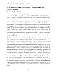
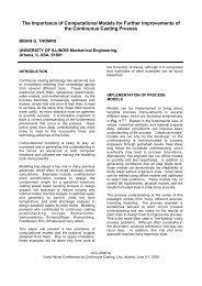
A schematic of part of the continuous casting process is<br />
depicted in Figure 1. Steel flows through the "tundish,"<br />
and then it exits down through a ceramic SEN and into the<br />
mold. Here, the steel freezes against the water-cooled cop-<br />
per walls to form a solid shell, which is continuously with-<br />
drawn from the bottom of the mold at a rate or "casting<br />
speed" that matches the flow of incoming metal. Flow<br />
through the SEN is gravity driven by the pressure differ-<br />
ence between the liquid levels of the tundish and mold top<br />
free surfaces. Thus, the flow rate depends upon the amount<br />
of steel in the tundish and the flow characteristics inside<br />
the SEN. The flow rate of molten steel is controlled to<br />
maintain a constant liquid level in the mold in several ways.<br />
In one method, a simple "stopper rod" pushes down<br />
through the tundish to partially plug the exit (not pictured).<br />
Alternatively, a "slide gate" blocks off a portion of the<br />
SEN pipe section by moving a disk-shaped plate through a<br />
horizontal slit across the entire SEN, as pictured in Figure<br />
FADY M. NAJJAR, formerly Research Assistant, Department of<br />
Mechanical and Industrial Engineering, is with the National Center for<br />
Supercomputing Applications, University of Illinois, Urbana, IL 61801.<br />
BRIAN G. THOMAS, Associate Professor, is with the Department of<br />
Mechanical and Industrial Engineering, University of Illinois, Urbana, IL<br />
61801. DONALD E. HERSHEY, formerly Research Assistant in the same<br />
department, is with G.E. Aircraft Engines, Cincinnati, OH 45215.<br />
Manuscript submitted June 23, 1994.<br />
Slide Gale "<br />
(flow contzol)<br />
Liquid Steel<br />
Copper Solid Mold Powder<br />
Mold I<br />
Liquid Mold Flux [<br />
iii!<br />
:i:i<br />
!iii<br />
%%,<br />
<strong>Continuous</strong> Withdrawal<br />
e~ence<br />
Depth<br />
slag layer<br />
~d Entry Nozzle<br />
(SEN)<br />
Fig. 1--Schematic of the continuous casting process showing tundish,<br />
SEN, and mold.<br />
1. This flow-adjustment method allows for independent<br />
control of casting speed and metal level and is also essential<br />
for stopping the flow of molten steel if the operation must<br />
be abruptly terminated.<br />
The primary functions of the SEN are to protect the mol-<br />
ten steel from reoxidation as the steel is delivered from the<br />
tundish to the mold and to control the flow of steel within<br />
METALLURGICAL AND MATERIALS TRANSACTIONS B VOLUME 26B, AUGUST 1995--749<br />
%,
the mold. The SEN has an important influence on steel<br />
quality through its effect on the flow pattern in the mold.<br />
The SEN should deliver steel uniformly into the mold while<br />
preventing problems such as surface waves, meniscus freez-<br />
ing, and crack formation. Impingement of hot liquid metal<br />
with high momentum against the solidifying shell can con-<br />
tribute to shell thinning and costly "breakouts," in which<br />
liquid steel bursts from the shell, t2J In addition, the SEN<br />
should be designed to deliver steel with the optimum level<br />
of superheat to the meniscus while preventing both detri-<br />
mental surface turbulence and shell erosion or thinning due<br />
to excessive impingement of the hot molten steel jets. In<br />
some operations, it is also important for the flow pattern to<br />
aid in the flotation of detrimental alumina inclusions into<br />
the protective molten slag layer. Plant observations have<br />
found that many serious quality problems are directly as-<br />
sociated with SEN operation and the flow pattern in the<br />
mold. TM For example, surface waves and turbulence near the<br />
top free surface can entrain some of the slag or gas bubbles<br />
into the steel, causing dangerous large inclusions and sur-<br />
face slivers, r3] Furthermore, plant experience has demon-<br />
strated the importance of the SEN on breakouts, surface<br />
inclusions from mold slag or argon entrapment, subsurface<br />
inclusions, and cracks of various types. Finally, clogging<br />
due to inclusion buildup on the SEN walls redirects the<br />
flow through the SEN and, hence, affects the jet character-<br />
istics exiting from the SEN ports.<br />
Past experimental work to understand how SEN design<br />
affects flow in the mold and associated phenomena has<br />
been performed primarily using water models of the SEN<br />
and moldy -u] Mills and BarnhardtU2] conducted experi-<br />
ments in freezing water models to study the effect of nozzle<br />
design on the alumina entrapment mechanism inside the<br />
mold cavity. They investigated two- and multiport nozzles<br />
and found a significant improvement in the flow pattern<br />
inside the mold cavity with multiport nozzles. Saito et aL u3j<br />
studied the flow patterns inside the mold cavity from four-<br />
port nozzles using water-modeling techniques. DawsonV41<br />
investigated inlet curvature of the bore using water-mod-<br />
eling and steel-casting experiments. Recently, Gupta and<br />
LahiritlS~ performed water-modeling experiments for noz-<br />
zles with different port angles and bore diameters in free-<br />
fall and submerged jets. Honeyands et aL u61 performed<br />
water-modeling experiments for SEN with various bore di-<br />
ameters, port angles, and heights and measured the jet angle<br />
and the effective port area. Further, numerical studies have<br />
been performed on the complex geometry of the SEN to<br />
complement the experiments, v~~ Wangt2~ has formulated<br />
a three-dimensional (3-D) finite-element model to study the<br />
asymmetrical flow through the SEN ports as a result of the<br />
slide gate position. Hershey et aL t221 have assessed the ac-<br />
curacy of the 3-D and two-dimensional (2-D) finite-element<br />
simulations of the flow in the SEN, through comparison<br />
with velocity measurements and water model observations.<br />
They demonstrated the feasibility and the reasonable ac-<br />
curacy of this approach, including the separation of the noz-<br />
zle, mold calculations, and the use of 2-D simulations.<br />
The present work extends the model of Hershey et alY 2~<br />
to investigate the influences of the nozzle geometry and the<br />
effects of operating conditions on flow inside the SEN. The<br />
SEN geometry is one of the few variables in continuous<br />
casting that is easy and inexpensive to change and also has<br />
an important influence on both productivity and product<br />
quality. Using the commercial finite-element code (FIDAP),<br />
2-D and 3-D simulations are performed to provide insights<br />
into the parameters that control the flow of liquid steel in<br />
the nozzle. These parameters are classified as SEN geom-<br />
etry (or design) and casting operation practices. The geo-<br />
metric parameters include the port angle, port height, port<br />
width, port dispersion angle, nozzle wall thickness, port<br />
curvature, and bottom shape. The process variables include<br />
the inlet velocity profile and angle as well as the port cur-<br />
vature due to nozzle erosion or inclusion buildup. The re-<br />
suits focus on the jet characteristics exiting the nozzle,<br />
including flow asymmetry, which is suspected to adversely<br />
influence the flow dynamics inside the caster. Finally, the<br />
results obtained from the finite-element model of the SEN<br />
are necessary to provide inlet boundary conditions for the<br />
simulations of flow inside the mold. I231<br />
A. Governing Equations<br />
II. MODEL FORMULATION<br />
The flow of molten steel through a bifurcated SEN into<br />
a continuous casting mold is inherently 3-D, time depend-<br />
ent, and turbulent. The Reynolds number, based on the noz-<br />
zle bore diameter (D), is typically of the order of 10 5.<br />
However, unsteady 3-D simulations are computationally in-<br />
tensive for the current geometrical configuration. As an in-<br />
itial step toward understanding the flow dynamics in<br />
bifurcated nozzles, the present work adopts a steady-state<br />
approach. Previous numerical studies [19,2~ have shown<br />
the feasibility and benefits of such an approach. The current<br />
numerical procedure solves the time-independent mass and<br />
momentum conservation equations for an incompressible<br />
single-phase Newtonian fluid given by the following:<br />
-<br />
0vi<br />
-- = 0 [1]<br />
Oxi<br />
- - + ") ", ox, ox, J<br />
where the indices i and j = 1, 2, and 3 represent the x, y,<br />
and z directions and repeated indices indicate summation.<br />
The time-mean velocities are denoted by vi = {vx, Vy, Vz}. In<br />
Eq. [2], p is the fluid density, /.to represents the molecular<br />
viscosity, and tt, is the turbulent (or eddy) viscosity.<br />
The two-equation K-e turbulence model is chosen to close<br />
the system of equations. This requires the solution of two<br />
additional transport equations to determine the turbulent ki-<br />
netic energy, K, and the turbulent dissipation, e, fieldsY 61<br />
P ~J~jxj :"~j ~'~j ~-ClK~J~t*iC2Og t4]<br />
where<br />
K 2<br />
/x, : Cu p -- [6]<br />
E<br />
750~VOLUME 26B, AUGUST 1995 METALLURGICAL AND MATERIALS TRANSACTIONS B
Restricted Inlet<br />
\<br />
Modelled Nozzle<br />
Submerged<br />
[] - "tz?,e<br />
let Angle, O!<br />
[] ~Nozzle Bore<br />
Port Angle,~, ]~<br />
1 ~ ~ ~PortHeight I-tp<br />
WollL o<br />
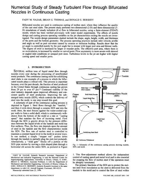
Fig. 2--Schematic of SEN with definitions of geometrical parameters.<br />
with C~ = 1.44, C2 = 1.92, C, = 0.09, o- k = 1.00, and<br />
~, = 1.30.<br />
Since the governing equations of the present study as-<br />
sume single-phase steady-state flow, phenomena related to<br />
argon gas injection in the nozzle tube and periodic sloshing<br />
or transient flow instabilities are not considered. Two-di-<br />
mensional simulations are also carried out on a computa-<br />
tional domain contained in the x-z plane. For these cases,<br />
the y-velocity component and the derivatives in the y di-<br />
rection are set to zero.<br />
B. Solution Procedure<br />
The governing Eqs. [1] through [6] were discretized us-<br />
ing the finite-element method and solved with the FIDAP<br />
code (<strong>version</strong> 6.01)F 7j The continuity equation (Eq. [1])<br />
was satisfied using the penalty function approach:<br />
0v,<br />
-- = -o-p [7]<br />
Ox~<br />
where o- is set to 10 -8 m 2 s -1 N -~.<br />
The computational domain is subdivided into discrete<br />
regions called elements. The dependent variables, ~, p, K,<br />
and e, are approximated in each element in terms of nodal<br />
values using interpolation "shape" functions, c271 Substitut-<br />
ing the discretized variables into the governing Eqs. [1]<br />
through [4] yields sets of residuals (errors). Applying Gal-<br />
erkin's method, the residuals are made orthogonal to the<br />
shape functions, thereby setting the weighted average error<br />
over the entire computational domain to zero. Assembly of<br />
the resulting equations integrated numerically over each el-<br />
ement produces a global system of nonlinear algebraic<br />
equations expressed as<br />
IS(u)] {u} = {r} [8]<br />
where [S(u)] is referred to as the stiffness matrix, {u} =<br />
Port Side Dispersion<br />
Angle, 0sd<br />
~k..~y ~-~ Port Width, %<br />
{~x, vy, v:, p, K, e} is the vector of unknown nodal values,<br />
and {F} is referred to as the force vector. Equation [8] is<br />
solved using a relaxed successive substitution scheme:<br />
[S(u"-~)] {u*} = {F} [9]<br />
{u "+~} = RF {u*} + (1 - RF) {u"} [10]<br />
where RF (relaxation factor) varies between 0 and 1.<br />
Numerical stability is maintained through a streamline-<br />
upwinding or Petrov-Galerkin formulation, t271 However, it<br />
should be noted that this formulation could introduce some<br />
false diffusion and has been reported to affect the flow in<br />
low velocity regions of the computational domain.t/8]<br />
C. Boundary Conditions<br />
The mathematical model of the nozzle is based on a typ-<br />
ical bifurcated SEN, such as was used in the steel slab<br />
casting operation at Inland Steel. Cross-sectional cuts<br />
through the inner tube and the outlet ports of the nozzle are<br />
illustrated in Figure 2. Two vertical symmetry planes par-<br />
allel to the central axis are taken through the center plane<br />
of the SEN and the middle of the ports to reduce the com-<br />
putational cost. The following boundary conditions are ap-<br />
plied along the computational domain:<br />
(1.) At the inlet to the SEN, a uniform z velocity (vzi,) was<br />
specified and calculated as follows:<br />
Aslab<br />
v~,. = vc-- [11]<br />
rrD2/4<br />
This boundary condition reasonably approximates the<br />
1/7 power-law turbulent profile expected in pipe flow<br />
away from the walls. The x and y components of ve-<br />
locity and the normal pressure gradient are set to zero.<br />
The inlet turbulent kinetic energy (Ki,) and dissipation<br />
(Ei,) are assigned the average values of the profiles cal-<br />
METALLURGICAL AND MATERIALS TRANSACTIONS B VOLUME 26B, AUGUST 1995--751
Table I. Standard Simulation Conditions where<br />
Nozzle dimensions:<br />
Bore diameter, D 76.0 mm<br />
Length - total 501.2 mm<br />
modeled, L 300.0 mm<br />
Port angle, 0p -15 deg<br />
Side dispersion angle, Osa 0 deg<br />
Port height, Hp 90.0 mm<br />
Port thickness, tp 25.5 mm<br />
Port width, Wp 60.0 mm<br />
Recessed bottom depth, LwD 13.0 mm<br />
Molecular viscosity,/z0 0.0056 kg m -1 s -l<br />
Density, p 7021 kg m -3<br />
<strong>Casting</strong> speed, V c 0.01563 m s -1<br />
Slab area, Aslab<br />
Inlet conditions:<br />
1.422 0.203 m 2<br />
x velocity, (v~)g. 0.0<br />
y velocity, (vy)~, 0.0<br />
z velocity, (v~)~, -1.0 m s -~<br />
Blockage ratio 0 pct<br />
Inlet flow angle, Oi 0 deg<br />
Turbulent kinetic energy, (K)~, 0.00425 m z s -z<br />
Dissipation, (e)~, 0.025 m z s -3<br />
Turbulent viscosity, (/x,)~,<br />
Initial guess<br />
0,457 kg m -~ s -1<br />
Velocity 0.0 m s -l<br />
Turbulent kinetic energy 0.0035 m 2 s -:<br />
Dissipation 0.020 m 2 s 3<br />
Inlet Reynolds number 95,285<br />
culated from a mixing-length model for turbulent pipe<br />
flow. [29,3~ Further details have been described else-<br />
where.tl9]<br />
(2.) The component of velocity normal to each symmetry<br />
plane is fixed to zero to prevent fluid from penetrating<br />
the surface. The normal gradients of the two remaining<br />
velocity components, the pressure, the turbulent kinetic<br />
energy, and the turbulent dissipation, are set to zero.<br />
These stress-free boundary conditions are also applied<br />
to all variables on the outlet plane of the port.<br />
(3.) Since the K-E turbulence model is of the high Reynolds<br />
number type, it should not be applied in the near-wall<br />
regions. Thus, the "law-of-the-wall" approach has<br />
been applied by creating near-wall elements along all<br />
wall surfaces. This approach captures the steep gradi-<br />
ents in the near-wall region without using excessive<br />
mesh refinement. The near-wall elements employ spe-<br />
cial shape functions based on Reichardt's law. t31,321 Ve-<br />
locity components at the stationary wall side are set to<br />
zero. Boundary conditions on K and 9 are applied at<br />
the fluid side of the near-wall elements as follows:<br />
OK<br />
-- = 0 [12]<br />
On<br />
e = K)I' [13]<br />
KA<br />
where K is the von-K~mfin constant with a value of<br />
0.41 and A is the element height. Since K and 9 are<br />
not defined within these elements, I.tt is based on van<br />
Driest's mixing length model given by<br />
[0~ t. 0V// 0Vjj)] 1/2 [14]<br />
and<br />
lm = KA [1 -- exp ( --A+/26)] [15]<br />
pcuO.25KO.S A<br />
A+ - [161<br />
/Xo<br />
Further details on the near-wall element formulation<br />
are given elsewhere. {22,27,33]<br />
D. Computational Details<br />
Table I summarizes the dimensions and the operating<br />
conditions for the base mathematical model. The 3-D finite-<br />
element mesh has 5415 nodes consisting of 4432 eight-<br />
node linear brick elements and 802 eight-node near-wall<br />
elements. The 2-D finite-element mesh has 1848 nodes con-<br />
sisting of 1740 four-node linear quadrilateral elements and<br />
154 two-node wall elements. The solution procedure dis-<br />
cussed in Section II-13 uses an RF of 0.7 during the initial<br />
five iterations and 0.85 for the subsequent ones. This strat-<br />
egy is found to accelerate the convergence rate of the so-<br />
lution.V8~ The 2-D and 3-D simulations require approxi-<br />
mately 25 iterations for the residual of the velocity field<br />
and the K and E fields to reach less than 1.2 and 3.0 pct,<br />
respectively. The computational costs of the 2-D and 3-D<br />
simulations are approximately 14.3 and 510 seconds of cen-<br />
tral processing unit (CPU) time per iteration, respectively,<br />
on a CRAY-2.*<br />
*CRAY is a trademark of Cray Research, Inc., Minneapolis, MN.<br />
In describing the flow at the nozzle outlet port, several<br />
parameters including jet speed, jet angle, jet spread angle,<br />
and turbulence intensity are determined. At specific points,<br />
these variables are defined as follows:<br />
(1.) the speed,<br />
(2.) the local jet angle,<br />
V = /Vx 2 + - vy2 + - v Z [17]<br />
Ozx = tan-' (Vz/Vx) [18]<br />
(3.) the local spread angle in the horizontal plane,<br />
and<br />
(4.) the turbulence intensity,<br />
Oyx = tan -l (vy/vx) [19]<br />
~-(v K) [20]<br />
I= 2<br />
Mean quantities are based on a weighted average of the<br />
area or the outflow mass rate and are defined as follows:<br />
(1.) the mean jet speed, /~,<br />
where<br />
fz = ~/fzx: + ~-y2 + re2 [21]<br />
752--VOLUME 26B, AUGUST 1995 METALLURGICAL AND MATERIALS TRANSACTIONS B
1.0 rn/s<br />
Z<br />
1<br />
I<br />
I<br />
I<br />
1<br />
I<br />
II<br />
I I<br />
i I<br />
i I<br />
t 9 o .<br />
I t . .<br />
,.I I , .<br />
I i 9 . .<br />
~tl II1<br />
tttlll<br />
~tt Ill<br />
-x\ \\~<br />
"-~ \\\<br />
I1. \<br />
Ii~, "x<br />
III ,,~<br />
ix,,,,.<br />
1.0 mls<br />
i , , 9 i III<br />
I I I f II I<br />
IIIIIll<br />
IIIIIII<br />
' ' I III<br />
- / I / 11<br />
i , , . . . .<br />
I i , , ,<br />
I I I<br />
I I<br />
' II<br />
II<br />
II<br />
iI<br />
I I<br />
"~z" /<br />
(a) Co) (c) (d) (e)<br />
Fig. 3~alculated velocities for standard 3-D SEN. (a) 3-D view, y-z cross-sectional cuts at (b) x = 0 mm, (c) x = 20 mm, (d) x = 40 mm, and (e) x<br />
= 63.5 mm (outlet plane of port).<br />
~ = , = (L), ~ (Ay), (,%),<br />
2 (ae),(az),<br />
, = 1<br />
(2.) the mean jet angle, 0=,<br />
0zx = tan -I '~ (vz)' V~ (Ay),<br />
Z<br />
, = 1<br />
(3.) the mean spread angle,/)~,<br />
~)~y = tan_ 1 ,~1<br />
k=x,y, orz [22]<br />
( ~ (~x)' Vi(Ay )i(Az)i)<br />
i ~=1 (~y)' wi (Ay)i (Az)i<br />
(4.) the mean turbulence<br />
]=?(R<br />
intensity, i,<br />
Vz,~ 2<br />
where<br />
[23]<br />
[24]<br />
[25]<br />
Z /q v, (Ay), (a=),<br />
/s = ' =N~E [26]<br />
Z Vi (hy)i (Az) i<br />
i = I<br />
(5.) the effective area fraction,/3, is defined as the fraction<br />
of the outlet port area where the flow has a positive x<br />
component of velocity, so it exits the nozzle domain.<br />
The rest of the port contains a recirculation region,<br />
where flow re-enters the nozzle.<br />
(6.) the mass flow rate ratio is defined as the ratio between<br />
the total mass flow rates exiting through the right and<br />
left ports and indicates asymmetry in the flow pattern.<br />
In Eqs. [21] through [26], ~ is the speed in one element<br />
(Eq. [17]), NE is the number of elements in that portion of<br />
the plane of the port outlet with positive x velocity, and Ay<br />
and A z are the element sizes in the y and z directions, re-<br />
spectively. It was found that ] almost doubles if a simple<br />
average is employed instead of the weighted average based<br />
on mass flow rate defined here.<br />
III. RESULTS<br />
Figure 3 presents velocity vectors for the flow field com-<br />
puted from the base problem in Table I. It is seen that the<br />
fluid exits the nozzle ports at a steeper downward angle<br />
than the -15 deg port angle. The mean jet angle, 0=, is<br />
calculated to be -24 deg, and the computed mean jet<br />
speed, I 7, is 0.94 m s -1. Further, it is observed that the flow<br />
exits from the bottom half of the outlet port, and a low-<br />
velocity recirculation region is present in the upper half of<br />
the port. The effective area fraction,/3, is computed to be<br />
0.60. Other published work [221 has verified that the current<br />
results agree with experimental observations and measure-<br />
ments in a full-scale water model of the slab casting pro-<br />
cess. The mean turbulence intensity, [, at the port outlet is<br />
calculated to be 0.15 and is found to be slightly underes-<br />
timated compared with the experimental measurements, t22]<br />
The results obtained from 3-D simulations predict very<br />
slight spreading of the jet as it crosses the plane of the<br />
nozzle outlet ports. The mean spread angle, 0~, is computed<br />
to be less than 1 deg. However, the local spread angle, 0 H,<br />
reaches a maximum value of 18 deg at the bottom of the<br />
METALLURGICAL AND MATERIALS TRANSACTIONS B VOLUME 26B, AUGUST 1995--753
port. This indicates that the jet exits the outlet port with a<br />
swirling velocity component, as shown in Figure 3. The<br />
exit vortex in the lower comer of the port emphasizes the<br />
three-dimensionality of the flow. However, based on a pre-<br />
vious study,t22~ the results obtained from the 2-D simula-<br />
tions are found to satisfactorily capture the mean flow<br />
characteristics. Hence, the predominant flow features are<br />
confined to the 2-D (x-z) plane. In the current study, 2-D<br />
numerical simulations are performed as appropriate to de-<br />
crease the computational requirements.<br />
IV. EFFECT OF NOZZLE DESIGN<br />
The design of the SEN geometry is crucial to the control<br />
and quality of the continuous casting process. One task is<br />
to maintain the desired flow rate of molten steel through<br />
the nozzle. Since casting operating conditions may span a<br />
wide range from start-up to shutdown, the final SEN design<br />
should be appropriately optimized.<br />
The direction of the jet discharge into the mold cavity<br />
should be designed to avoid both shallow and deep jet an-<br />
gles according to the mold width, casting speed, and other<br />
casting conditions. A shallow mean jet angle may deliver<br />
the molten steel directly to the meniscus, resulting in sur-<br />
face turbulence and promoting the entrainment of mold slag<br />
into the liquid steel. This disrupts solidification near the<br />
meniscus, which is critical to surface quality. Then, after<br />
solidification, entrained mold slag can cause the formation<br />
of detrimental complex aluminum-, silicon-, and calcium-<br />
based oxide inclusions. When these oxides are present near<br />
the surface of the steel slab, critical line defects (slivers)<br />
are formed in the rolled product.<br />
A steep jet angle may drive the steel too deep into the<br />
mold and inhibit the flotation of inclusions and their re-<br />
moval by the slag layer. It may also cause the molten steel<br />
to lose its superheat by the time it reaches the meniscus.<br />
This promotes freezing of the meniscus, which may cause<br />
deep oscillation marks, consistent poor quality problems,<br />
and even "bridging" (in which the top surface of the steel<br />
freezes across the distance between the SEN and the wide<br />
face of the mold). These problems likely explain the poor<br />
performance of "straight-through" nozzle tubes with open<br />
bottoms.[lOl<br />
Furthermore, driving the jet of hot molten steel at high<br />
speed directly toward the solidifying shell can be detrimen-<br />
tal. If the superheat and casting speed are high, then the<br />
heat delivered by the impinging jet to the inside of the<br />
narrow face shell may exceed the heat extraction from the<br />
shell exterior, which results in shell erosion in local thin<br />
spots and may cause a breakout. High-speed flow toward<br />
the narrow face also increases the extent of surface level<br />
variations r341 and encourages detrimental vortex formation<br />
and the accompanying entrainment of mold slag. High-<br />
speed flow from the nozzle also inhibits the flotation of<br />
inclusions and argon bubbles, which leads to serious sur-<br />
face defects in the final product.<br />
Finally, temporal variation and spatial inhomogeneity of<br />
the flow exiting the port may cause surface turbulence,<br />
rapid surface level fluctuations, sloshing, and entrainment<br />
of mold slag into the liquid steel. Although these phenom-<br />
ena are difficult to predict with steady-state computations,<br />
high turbulence intensity (large 1) and a large recirculation<br />
zone in the top portion of the nozzle (small /3) are two<br />
strong indicators of turbulent fluctuations, which may lead<br />
to these causes of severe quality problems. Similarly, a<br />
large degree of swirl (as indicated by the local dispersion<br />
angle) may be detrimental. In addition, the ineffective area<br />
of the port may be more prone to detrimental inclusion<br />
buildup and clogging of the nozzle.<br />
This section studies the relative contribution of various<br />
nozzle geometric design variables on the important char-<br />
acteristics of the jet exiting the nozzle. The investigated<br />
parameters include port angle, height, width, thickness, side<br />
dispersion angle, port shape, number of ports, and bottom<br />
geometry.<br />
A. Port Angle, 0 v<br />
The primary function of the angle built into the SEN<br />
ports is to direct the molten steel jet at a desired angle from<br />
the SEN into the mold cavity. Plant observations and full-<br />
scale water experiments report a close relation between the<br />
exit jet flow characteristics and the SEN outlet port an-<br />
gle. tS,15.17j The present simulations are performed for port<br />
angles varying from +30 to -30 deg (upward and down-<br />
ward port angles are denoted with + and - sign, respec-<br />
tively). Other modeling parameters are set to the values in<br />
Table I. Figure 4(a) shows the velocity vector field for a<br />
nozzle with + 15 deg port angle. It is observed that the jet<br />
has a predominant negative (or downward) x-velocity com-<br />
ponent with 0= of -10 deg. Table II summarizes the jet<br />
mean speed, angle, effective area fraction, and mean tur-<br />
bulence intensity for port angles of -30 deg, -15 deg, 0<br />
deg, +15 deg, +30 deg.<br />
It is seen that, for all the port angles investigated, the jet<br />
discharges from the nozzle with a larger downward angle<br />
than the port edges. Similar observations were made by<br />
Gupta and Lahiri.t15~ In their water-modeling experiments,<br />
jet angles of -32, -15, and -9 deg were measured for<br />
nozzle port angles of -25, 0, and +15 deg, respectively.<br />
The present computed jet angles closely agree with these<br />
experimental values. Due to the slow-moving fluid in the<br />
recirculation region in the upper ineffective portion of the<br />
port, the angle of the top edge of the port does not affect<br />
the jet direction. This corroborates the water-modeling ex-<br />
periments of McPherson, t8~ who varied the upper and lower<br />
port angles independently and fotmd that the jet direction<br />
is not influenced by the angle of the top edge of the port.<br />
Although the average spread angle remains fairly con-<br />
stant at 0.8 deg for several port angles, the maximum local<br />
spread angle, (OaT)max , increases from 18 deg for a -15 deg<br />
port angle to 24 deg for a + 15 deg port angle. This indi-<br />
cates that the swirling component increases with the port<br />
angle. The experimental measurements of Gupta and La-<br />
hiritlsJ report similar trends. Finally, the mean jet speed de-<br />
creases, and the effective area fraction increases with<br />
decreasing port angle, while the mean turbulence intensity<br />
remains nearly constant.<br />
B. Port Height, Hp<br />
The influence of port height was investigated for various<br />
port angles using the 2-D model. Figure 4(b) presents the<br />
velocity vector field for + 15 deg SEN with port height, lip,<br />
of 45 mm. Comparing the velocity vectors in Figures 4 (a)<br />
and (b) shows that the jet aligns itself closer to the nominal<br />
754---VOLUME 26B, AUGUST 1995 METALLURGICAL AND MATERIALS TRANSACTIONS B
: :'. ~<br />
: ;z :<br />
~,',4<br />
1.0 m/<br />
l tltllllllllllllllJll<br />
. 11111 llllt<br />
(a) ] (b)<br />
X<br />
Fig, 4--4Salculated velocities in the port vicinity for a +15 deg SEN: (a) Hp = 90 mm and (b) lip = 45 mm.<br />
port angle when the port height is smaller. The mean jet<br />
angle is +2.5 deg for Hp = 45 mm compared with -10<br />
deg for Hp = 90 mm (Table II).<br />
The mean jet velocities (17) are 0.99 and 1.6 m s -1, and<br />
the turbulence intensities (/) are 0.12 and 0.18 for 90- and<br />
45-mm port heights, respectively. These increases in/? and<br />
] for Hp = 45 mm are caused by the greater constriction<br />
imposed on the flow through a port with a smaller height.<br />
The current results agree with the measurements of Honey-<br />
ands et aL [161 The computations performed ona SEN with<br />
- 15 deg port angle show similar trends where 0= decreased<br />
from -24 deg to -18 deg and ] increased from 0.12 to<br />
0.19 for 90-mm and 45-mm ports, respectively.<br />
The effective area fraction (/3) is also found to increase<br />
to 0.75 for the smaller port height, as seen in Figure 4 (b).<br />
This is expected to reduce alumina buildup and SEN block-<br />
age. Based on water-modeling experiments on a nozzle<br />
with round ports and an inner nozzle (bore) diameter of<br />
250 mm, Honeyands et aLt~6j have correlated/3 to the ratio<br />
of the total port area to the bore area. They found that,<br />
below a port-to-bore ratio of 1, /3 is 1; while for port-to-<br />
bore ratios above 1,/3 decreases. In Figure 4, the port-to-<br />
bore ratio is 1.2 for Hp = 45 mm and 2.4 for the base<br />
conditions, Hp = 90 mm. The presence of the detrimental<br />
recirculation zone (/3 < 1) is predicted for both port<br />
heights, which is consistent with Honeyands.t~61 In Section<br />
IV-F, it is shown using 3-D simulations that nozzles with<br />
port-to-bore ratios less than 1 have /3 = 1. This provides<br />
further agreement with Honeyands et aL t~6]<br />
C. Port Thickness, tp<br />
The bore diameter limits the maximum attainable casting<br />
speed while the outer diameter must fit easily inside the<br />
mold cavity. Half the difference between these two diam-<br />
eters corresponds to the port thickness, tp, and represents<br />
another SEN design variable influencing the exit jet. Two-<br />
dimensional simulations were performed for the port<br />
heights of 45 and 90 mm and port angles of ___ 15 deg with<br />
varying tp from 12 to 76 mm.<br />
Figure 5 illustrates the velocity vector field obtained with<br />
Table II. Mean Jet Characteristics for Various Port Angles<br />
Based on Two-Dimensional Simulations<br />
(Deg) (m s-') (Deg)<br />
+30 1.01 -4 0.52 0.13<br />
+15 0.99 -10 0.57 0.12<br />
0 0.98 -17 0.58 0.11<br />
- 15 0.97 -24 0.62 0.12<br />
-30 0.94 -32 0.68 0.13<br />
increasing tp for the otherwise base conditions of Table I. It<br />
is observed that the jet becomes more aligned with the port<br />
angle as ~ increases. Specifically, as tp increases from 12 to<br />
76 mm, 0~ changes from -29.6 deg to -16.1 deg, tending<br />
asymptotically toward the port angle of - 15 deg. Figure 6(a)<br />
illustrates this trend, showing that 0zx converges to the port<br />
angle even faster for the shorter 45-mm port height.<br />
Figures 6(b) and (c) present the variation of mean tur-<br />
bulence intensity and effective area fraction with tp at dif-<br />
ferent port heights and angles. The mean turbulence<br />
intensity decreases slightly with increasing port thickness<br />
and is not affected by the port angle (Figure 6(b)). The<br />
effective area fraction does not change much with tp in the<br />
90-mm port height but increases to 1 at 76-mm thickness<br />
in the 45-mm port height.<br />
The local jet angle (0~) is almost constant for large tp,<br />
as compared to small tp, where it could vary up to 25 deg<br />
(Figures 5(a) and (d)). This result implies that thicker ports<br />
reduce spreading of the jet. This finding explains the prac-<br />
tice of adding "ears" (extensions) to the sides and bottom<br />
of the nozzle ports. Ears act to increase the effective port<br />
thickness and, therefore, should induce the jet to follow the<br />
angle of the ports more closely and reduce its spread.<br />
D. Port Width, Wp<br />
Three-dimensional simulations were carried out to study<br />
the effects of the port width, Wp, on the jet characteristics.<br />
Specifically, port widths of 30, 45, and 60 mm were studied<br />
for the conditions in Table I. The speed profiles down the<br />
METALLURGICAL AND MATERIALS TRANSACTIONS B VOLUME 26B, AUGUST 1995--755
(a)<br />
,"N}#%<br />
iifN<br />
(b)<br />
1.0 m/s<br />
~'.:..<br />
(e)<br />
! ,ii+i><br />
Fig. 5~alculated velocities in the port vicinity for various SEN thicknesses: (a) tp = 12 mm, (b) tp = 25.5 mm, (c) tp = 38 mm, and (d) tp = 76 mm.<br />
centerline of the outlet port, plotted in Figure 7, are seen<br />
to be relatively uniform in the lower portion of the SEN<br />
port for all port widths investigated. As Wp decreases, the<br />
uniform-speed profile extends over a larger portion of the<br />
outlet area and has a slightly higher magnitude.<br />
Table III summarizes the jet characteristics obtained from<br />
these simulations. It is observed that halving W e from 60<br />
to 30 mm increases I > by 25 pct,/3 by 60 pct, and ,? by 53<br />
pct. These increases in mean jet speed and effective port<br />
area are a result of mass conservation. At a constant casting<br />
speed, the jet exits from a larger portion of the outlet area<br />
for a narrower port width, so /3 increases accordingly.<br />
Though the effective area fraction increases, the total port<br />
area decreases more, so the jet speed increases slightly (Figure<br />
7) and becomes more turbulent. The mean jet angle and<br />
mean spread angle are nearly independent of Wp. However,<br />
the local spread angle decreases greatly with decreasing Wp<br />
as the side walls channel the flow through a narrower area.<br />
This reduces the swirling motion, which is evident from the<br />
small maximum local spread angle of only 7 deg for the<br />
30-mm port width.<br />
E. Port Side Dispersion Angle, Osd<br />
The port side dispersion angle, 0sa, is defined as the hor-<br />
izontal (x-y) angle between the plane of the side wall and<br />
the symmetry plane (Figure 2). A 3-D simulation was per-<br />
formed for a SEN with a port width of 45 mm at the inner<br />
diameter and 54 mm at the outer diameter, which resulted<br />
in 0,~ of 10 deg. Figure 8 shows the computed velocity<br />
vector field in the x-y plane at two different cross sections<br />
taken at 5.4 and 16.1 mm from the port bottom plane. The<br />
flow inside the port is observed to conform with the hori-<br />
zontal spread of the side walls. This effect is more pro-<br />
nounced near the port bottom (5.4 mm). The calculated<br />
maximum jet spread angle, 0~y, is 23 deg compared with<br />
14 deg for a SEN with a zero dispersion angle. The mean<br />
jet spread is computed as 5 deg for 0sa of 10 deg. The mean<br />
jet speed increases slightly and the mean jet angle is steeper<br />
by 5 deg for the SEN with the widening 0s~, as compared<br />
with the standard SEN (Table III). The effective area frac-<br />
tion is 0.72 for 0sa = 10 deg and, hence, falls within the<br />
computed range for 45- and 60-mm port widths (0.58 < 13<br />
< 0.78).<br />
Experimental observations have reported an increase in<br />
the surface turbulence for rectangular ports with diverging<br />
side walls. This effect is believed to be caused by an in-<br />
crease of the jet spread in the x-y plane, 0,~,. [31 Indeed, the<br />
current numerical results show a fivefold increase in jet<br />
spread leaving the port with the side-dispersion angle.<br />
However, the small magnitude of the spread suggests that<br />
surface effects are not caused directly by mean spreading<br />
of the jet through the nozzle outlet. Further jet spread is<br />
likely induced after the flow enters the mold cavity, pos-<br />
sibly aided by increased swirl component.<br />
F. Port Shape<br />
Port shapes in operation range from rectangular, square,<br />
circular, oval, dome-topped square, pear-shaped, to other<br />
variations. To investigate the relevance of the port shape,<br />
3-D computations were performed to compare port geom-<br />
etries with square (45 45 mm 2) and circular (51-mm<br />
diameter) cross sections, with the same port-to-bore area<br />
ratio of 0.90 and a -25 deg angle SEN. The calculated<br />
velocity vector fields are presented in Figure 9. Flow inside<br />
the port is seen to fill the entire outlet area in both geom-<br />
etries (/3 = 1), although a recirculating volume is confined<br />
inside the port without extending to the port opening. This<br />
is consistent with the criterion of Honeyands et aLtO61 that<br />
/3 = 1 when the port area is smaller than the bore area. An<br />
effective area fraction of one should be beneficial by re-<br />
ducing turbulent fluctuations and discouraging the buildup<br />
of alumina inclusions inside the port.<br />
The mean jet speed, angle, and spread angle shown in<br />
Table IV are similar for the two port shapes. For example,<br />
the maximum spread angles at the port outlet are 5 deg and<br />
8 deg for the square and circular ports, respectively. These<br />
values are considerably smaller than those of the standard<br />
SEN with its oversized ports (Table III), indicating signif-<br />
icantly less swirl for the smaller ports. The slightly higher<br />
756 VOLUME 26B, AUGUST 1995 METALLURGICAL AND MATERIALS TRANSACTIONS B
40.0<br />
30.0<br />
20.0<br />
~ -"<br />
".'.:: ,<br />
S<br />
eSO = I0"<br />
5.4 mm<br />
. . 9 ~, \ \ \<br />
~,,',\\\\<br />
\,\\\\\\<br />
t I<br />
(a) (b)<br />
Fig. 8--Calculated velocities above the port bottom for a 10 deg side dispersion SEN: (a) 5A mm from bottom of port and (b) 16.1 mm from bottom of<br />
port.<br />
..:' l': j" i,'h<br />
Fig. 9-~;alculated velocities at port outlet for different port geometries: (a) circular and (b) square.<br />
may influence the propensity to generate sudden fluctua-<br />
tions, especially when accompanied by unsteady operating<br />
conditions such as start-up transients and changes in the<br />
casting speed. Further numerical analysis and experimental<br />
data are needed to quantify these issues.<br />
H. Number of Ports<br />
In attempting to alleviate problems related to nozzle per-<br />
formance, many innovative SEN designs have been sug-<br />
gested to improve the jet characteristics exiting from the<br />
ports. [5,1~ Increasing the effective port area and enhancing<br />
the effectiveness of the port edges in directing the jet are<br />
two possible criteria for SEN design. Sections IV-B and<br />
IV-C have shown that the jet tends to align itself closer<br />
with the port angles as the ports become thicker and shorter.<br />
The results of this work suggest that increasing the aspect<br />
ratio of port thickness (tp) to height (Hp) could improve the<br />
Table IV. Jet Characteristics for Various Port Geometries<br />
Based on Three-Dimensional Simulations<br />
Port Shape (rn s -1) (Deg) (Beg) (Beg)<br />
Square<br />
(45 45 mm 2) 1.37 -23 0.27 1 5<br />
Circular<br />
(51-mm ID*) 1.34 -25 0.20 1 8<br />
*ID = inside diameter<br />
effectiveness of the SEN in directing the flow (other factors<br />
remain constant). However, ports with oversized dimen-<br />
sions are widely used in casting plants because they have<br />
a high safety margin before total blockage of the SEN by<br />
inclusion buildup. One way to satisfy both of these requi-<br />
rements simultaneously is to employ more than two ports.<br />
758--VOLUME 26B, AUGUST 1995 METALLURGICAL AND MATERIALS TRANSACTIONS B
(a) (b)<br />
I I<br />
1.0 m/s i<br />
/<br />
X <<br />
...:::,,, i;<br />
"". "#l<br />
Fig. l~alculated velocities for various bottom designs: (a) recessed, (b) flat, and (c) pointed.<br />
Table V. Mean Jet Characteristics for SEN Bottom Design<br />
Based on Two-Dimensional Simulations<br />
Op Bottom Design 17 ~x i<br />
(Deg) (m s 1) (Deg)<br />
flat 0.90 -23.8 0.06<br />
- 15 pointed 0.95 -23.7 0.08<br />
recessed 0.97 -24.0 0.12<br />
flat 1.04 -6.0 0.10<br />
+15 pointed 1.05 -5.6 0.12<br />
recessed 0.99 - 10 0.12<br />
Uniformly distributing multiple ports around the nozzle<br />
perimeter has been experimentally investigated in the<br />
past. t121 The port angle of a multiport SEN is able to direct<br />
the flow more effectively than the port angle of a bifurcated<br />
SEN with the same total outlet area. However, these mul-<br />
tiport nozzles are more prone to generate meniscus turbu-<br />
lence because they direct some of their flow toward the<br />
nearby wide faces. Another feasible multiport SEN design<br />
is to place additional ports directly above the existing ports<br />
of a conventional bifurcated design. This was successfully<br />
implemented in plant operations by Saito. t131<br />
Two-dimensional simulations were carried out for a four-<br />
port SEN. The port heights and thicknesses are 20 mm. The<br />
bore diameter is 120 mm at the inlet and 26 mm at the<br />
bottom, which gives the nozzle a funnel shape with a 15<br />
deg funnel angle. Figures 1 l(a) and (b) illustrate the veloc-<br />
ity vector field and mean port exit parameters for - 15 deg<br />
and + 15 four-port funnel nozzles (only half the model is<br />
shown). Flow is seen to exit the lower ports at a slightly<br />
lower mean jet angle with higher effective area fraction<br />
than the upper ports. It is observed that 70 pct of the inlet<br />
mass flow rate exits from the lower port. The mean tur-<br />
bulence intensity is higher in the lower port than in the<br />
upper one.<br />
Evidently, the four-port funnel SEN can control the jet<br />
direction more effectively than the standard two-port bifur-<br />
cated nozzle. It does not eliminate the recirculation zones<br />
at the port exits, and the 15 deg funnel angle is not enough<br />
to achieve equal flow through the top and bottom ports.<br />
However, the peak velocity at port exit is decreased from<br />
1.6 m s -1 (standard two-port) to 1.2 m s -x (upper four-port)<br />
and 1.3 m s -~ (lower four-port). Success achieved in plant<br />
operations with four-port submerged entry nozzlest~31 might<br />
be attributed to the longer flotation time available in the<br />
mold for inclusions and bubbles at these lower velocities.<br />
(c)<br />
V. EFFECT OF CASTING OPERATION<br />
VARIABLES<br />
The amount of steel fed through the SEN and subse-<br />
quently into the mold is controlled by either a slide gate<br />
valve or a stopper rod (Figure 1). Flow patterns in the tun-<br />
dish and the position of the slide gate or stopper rod can<br />
greatly vary the inlet boundary conditions to the SEN. Wa-<br />
ter-modeling experiments and plant operations often en-<br />
counter surface turbulence and quality problems that have<br />
been associated with highly asymmetrical flow patterns at<br />
the outlet ports. These asymmetrical flows might be attrib-<br />
uted to high casting speed, asymmetric inlet conditions, and<br />
partial clogging of the SEN bore and ports. This section<br />
investigates the effects of operating practices on the flow<br />
through the SEN including inlet opening area, inlet flow<br />
angle, casting speed, port curvature, and size asymmetry<br />
caused by nozzle erosion and clogging. Simulations are per-<br />
formed on the full section through the SEN with the 2-D<br />
model and are based on the conditions given in Table I.<br />
A. Restricted Inlet Opening Area<br />
Flow control mechanisms, such as slide gates and stopper<br />
rods, are installed at the inlet of the nozzle tube and operate<br />
METALLURGICAL AND MATERIALS TRANSACTIONS B VOLUME 26B, AUGUST 1995--759
z~.4~ x<br />
^<br />
0zx -- -14.9 ~<br />
=0.07<br />
13 = 0.65<br />
A<br />
Ozx = -18.5 ~<br />
=0.10<br />
[3 =0.89<br />
til A<br />
(a) fb)<br />
Fig. 11--Velocity vector field of a four-port funnel nozzle: (a) 0p = -15 deg and (b) 0, = +15 deg.<br />
in a fully open or partially closed position according to the<br />
process requirements. To numerically model a restricted in-<br />
let, velocity is set to zero across a fraction of the inlet<br />
(referred to as the blockage ratio), while velocity is in-<br />
creased over the rest of the inlet to conserve the mass flow<br />
rate. The inlet boundary conditions are based on velocity<br />
profiles referred to as skewed and centered.<br />
In the skewed configuration, flow is restricted to enter<br />
the SEN through only a fraction of the inlet from the right<br />
side. Figure 12(a) presents the calculated velocity vector<br />
field for a skewed inlet profile restricted to 50 pct of the<br />
nozzle bore diameter. Recirculation zones develop near the<br />
inlet inside the nozzle bore. This is potentially detrimental<br />
to the nozzle performance because nonmetallic inclusions<br />
tend to adhere more easily to the nozzle walls in separated<br />
flow regions and can lead to nozzle clogging.V41 Simula-<br />
tions undertaken with different blockage ratios of the inlet<br />
diameter show that the length of the upper recirculating<br />
zone extends farther inside the tube with increasing block-<br />
age of the inlet area.<br />
Asymmetrical profiles in the velocity at the nozzle port<br />
exits are also induced as a result of the skewed inlet profile.<br />
Table VI summarizes the mean jet angles, the mass flow<br />
rate fractions, and the mean turbulence intensities from the<br />
right and left ports for different inlet blockage ratios. The<br />
flow leaving the left port has a shallower jet angle and a<br />
Ozx = +12.0 ~<br />
=0.10<br />
p = 0.65<br />
^<br />
Ozx = +9.6 ~<br />
=0.18<br />
=0.74<br />
higher mass flow rate as compared with the right port. It is<br />
interesting to note that the flow enters the nozzle from the<br />
right side but exits predominantly from the left port. The<br />
asymmetry in the flow exiting the ports is greatly accen-<br />
tuated with increasing port blockage. The high blockage<br />
ratio of 75 pct is commonly encountered in plant operations<br />
during casting slowdowns. For this extreme operating con-<br />
dition, twice as much flow exits the left port than the fight<br />
port. These trends agree qualitatively with the numerical<br />
simulations of Wang [361 on slide gate designs. The mean<br />
turbulence intensity is higher for the left port (where more<br />
flow discharges) and also increases with higher blockage<br />
ratios.<br />
In the centered configuration, the flow is restricted to<br />
enter the SEN symmetrically through the center of the inlet.<br />
Figure 12(b) illustrates the velocity vector field with a 50<br />
pet centered blockage ratio. As opposed to the skewed inlet,<br />
the flow exiting the ports is perfectly symmetrical and the<br />
recirculation zones near the inlet do not extend as far into<br />
the SEN tube. The jet characteristics are similar for both<br />
ports and match the results for the base conditions.<br />
B. Inlet Angle<br />
The effect of varying the inlet angle of the flow into the<br />
SEN was studied by introducing a velocity component in<br />
760---VOLUME 26B, AUGUST 1995 METALLURGICAL AND MATERIALS TRANSACTIONS B
(a) (b)<br />
.0 m/s<br />
Fig. 12~alculated velocities for various inlet conditions: (a) skewed<br />
with 50 pet blockage ratio and (b) centered with 50 pct blockage ratio.<br />
Table VI. Effects of Blockage Ratio for Skewed Inlet<br />
Profiles on Jet Characteristics<br />
Blockage 0= Mass Flow (Pct) ]<br />
Ratio Left Port Right Port Left Right Left Right<br />
(Pet) (Deg) (Deg) Port Port Port Port<br />
25 - 19.3 -22.6 52 48 0.26 0.22<br />
50 -18.0 -26.5 57 43 0.30 0.26<br />
75 -3.4 -23.0 67 33 0.39 0.32<br />
~m/s<br />
z<br />
z<br />
x, l<br />
Fig. 13~alculated velocity vector for (a) 0z = 20 deg with no blockage<br />
and (b) 01 = 5 deg with 50 pct blockage ratio.<br />
METALLURGICAL AND MATERIALS TRANSACTIONS B<br />
Table VII. Effect of Inlet Flow Angle on Jet<br />
Characteristics<br />
Blockage t~= Mass Flow (Pct)<br />
Ratio Inlet Angle Left Port Right Port Left Right<br />
(Pct) (Deg) (Deg) (Deg) Port Port<br />
0 5 -20 -18 48 52<br />
20 -22 -16 44 56<br />
50 5 -20 -25 54 46<br />
20 -24 -21 47 53<br />
the x direction (vx) to the inlet velocity. This could arise in<br />
the plant from nonsymmetric flow in the tundish or while<br />
passing through the slide gate. Two-dimensional simula-<br />
tions with inlet angles of 5 and 20 deg were perfgrmed.<br />
The inlet angle is measured in the clockwise direction from<br />
the positive z-axis.<br />
Figure 13(a) shows the effect of an inlet angle of 20 deg<br />
on the velocity vector field with a fully opened inlet. It is<br />
seen that flow through the nozzle outlet ports is asymmet-<br />
rical. This is further evident from the jet characteristics<br />
summarized in Table VII. It is observed that the right port<br />
has a shallower mean jet angle (-16 deg) than the left port<br />
(-22 deg) and an increased mass rate (as indicated by the<br />
mass flow rate ratio between the right and left ports of<br />
1.27). Furthermore, increasing the inlet angle tends to am-<br />
plify this effect, which enhance the mass rate through the<br />
right port. This is roughly equal and opposite to the effect<br />
of increasing the blockage ratio through a skewed, re-<br />
stricted inlet, which increases flow through the lef[ port.<br />
Thus, comparing Figures 12(a) and 13(a) reveals that the<br />
flow patterns exiting the ports are asymmetrical in a reverse<br />
manner. The corresponding mass flow rate ratio for the 0<br />
deg inlet angle with 50 pct skewed blockage is 0.75.<br />
Figure 13(b) displays the combined effect of a 5 deg<br />
angled inlet flow and 50 pct skewed blockage on the ve-<br />
locity vectors. The left port has only a slightly steeper mean<br />
jet angle (-24 deg) than the right port,(-21 deg) and the<br />
mass flow rate ratio is 0.85. This is slightly more symmet-<br />
rical than the 50 pct blocked inlet with zero angle (Figure<br />
12(a)). Thus, the flow asymmetry introduced by the 5 deg<br />
inlet angle has partly compensated the skewed inlet profile.<br />
This is significant because the actual slide gate geometry<br />
(modeled by Wang t361) appears to introduce both the block-<br />
age and the inlet angle. It is evident from the current sim-<br />
ulations that small variations in the inlet conditions to the<br />
SEN, especially those that vary the inlet angle, can produce<br />
large differences in the jet characteristics and asymmetry at<br />
the outlet ports.<br />
DawsonV4J conducted experiments on fully open round<br />
nozzles with tilted inlet flow angles and has shown the pres-<br />
ence of flow separation near the top of the SEN. This sep-<br />
aration zone was observed to expand with increasing tilt<br />
angle. In the current study, this presence of a separation<br />
zone was observed with partly blocked nozzles but could<br />
not be captured with a fully opened inlet. The disagreement<br />
of the mathematical model with these experiments might<br />
be attributed to the two-dimensionality assumption, an in-<br />
complete priming of the nozzle tube, differences in the inlet<br />
boundary conditions, or deficiencies in the K-e turbulence<br />
model.<br />
Periodic variations in the SEN inlet conditions, such as<br />
VOLUME 26B, AUGUST 1995--761
those caused by slide gate movement, could be associated<br />
with flow instabilities at the steel surface in the mold.<br />
Downstream flow instabilities are more likely when small<br />
disturbances in the inlet conditions grow and are sustained<br />
at the outlet. Based on current simulations, these instabili-<br />
ties are more prone to develop for the partly blocked inlet.<br />
However, many other potential factors likely interact with<br />
these inlet effects to induce the observed surface turbulence<br />
phenomena. These factors include flow instabilities in the<br />
mold, the effects of argon gas, and the inherent dynamic<br />
nature of turbulent flow in both the SEN and the mold.<br />
These phenomena remain to be investigated.<br />
C. Port Curvature<br />
Nozzle erosion and inclusion buildup are problems com-<br />
monly encountered during casting. They ultimately lead to<br />
poor nozzle performance and corresponding quality and<br />
production losses. To simulate erosion of the port walls and<br />
inclusion buildup, a smooth curve is introduced along the<br />
upper edge of the outlet ports. The curvature chosen is typ-<br />
ical of that observed in partially clogged nozzle ports. Fig-<br />
ure 14(a) shows the velocity vector field for a 90-mm port<br />
height. The effective area fraction increases to 0.72, as<br />
compared with 0.65 for the standard SEN. As discussed in<br />
Section IV-A, the jet angle is not influenced by the cur-<br />
vature of the top edge when a large recirculation zone is<br />
present.is]<br />
The velocity vectors are plotted in Figure 14(b) for a<br />
curved port with a 53-mm height. In this case, the flow<br />
does not separate from the top comer, and the full area of<br />
the port is effectively used (/3 = 1). Smooth curved surfaces<br />
delay (Figure 14(a)) or eliminate (Figure 14(b)) the flow<br />
separation from the tube walls by decreasing the adverse<br />
pressure gradient. Preventing the formation of the recircu-<br />
lation region near the top edge of the port should be ben-<br />
eficial by reducing inclusion buildup, transient surging, and<br />
suction of mold fluid back inside the nozzle port.<br />
D. Asymmetrical Port Size<br />
The SEN is designed for steel casting applications, with<br />
the combined area of the ports being larger than bore area.<br />
This is done to reduce the flow restriction caused by the<br />
ports and to accommodate some inclusion buildup in the<br />
port without affecting the flow of molten steel into the<br />
mold. However, the current study has showed that over-<br />
sized ports decrease the effective area fraction and cause<br />
the formation of a detrimental low-velocity recirculation<br />
zone (Figure 4). This may contribute to inclusion buildup<br />
in the upper port edge. When the inclusion buildup occurs<br />
at a faster rate on one port than the other, the effective<br />
outlet area of the two ports differs.<br />
Simulations were conducted to model the asymmetrical<br />
clogging effect, first by considering unequally sized ports;<br />
the left port height was decreased to 81 mm and the right<br />
port height was increased to 99 mm. It was observed that<br />
the jet characteristics were very similar for the two ports,<br />
since only the top recirculation zone was affected. [25] Water-<br />
modeling experiments have reported increased surface tur-<br />
bulence problems associated with unequally sized ports.<br />
Current model results suggest that differences in port size<br />
o.- 9<br />
".oo .'li<br />
- ..'fl<br />
l;;,,:;'///,<br />
j;:,JT/?/h<br />
x i I<br />
(a) (b)<br />
i I<br />
!<br />
!:<br />
1.0 m/s<br />
Fig. 14~Calculated velocities for (a) H e = 90 mrn with curved upper<br />
edge and (b) H e = 53 mm with curved upper edge.<br />
are only important when the effective area fraction is af-<br />
fected, which occurs for small ports or large changes in<br />
port size.<br />
Next, the effects of more severe clogging of a 53-mm<br />
left port are investigated with square and curved upper<br />
edges. The height of the right port is 90 ram. Figures 15(a)<br />
and (b) present the velocity vectors for the square and<br />
curved edges, respectively. The mean jet angle is computed<br />
to be -16 deg from the clogged left port with a sharp<br />
square comer and -21 deg from the right port (Figure<br />
15(a)). The mass flow ratio between the right and left ports<br />
is 1.19. For the clogged port with a curved comer (Figure<br />
15(b)), the flow separation region is eliminated inside the<br />
left port. The mean jet angle is -23 deg from the left port<br />
and -17 deg from the right port, and the mass flow rate<br />
ratio is 0.81. Hence, it is evident that the flow asymmetry<br />
has ben switched between the configurations in Figures<br />
15(a) and (b). This occurred because the flow did not sep-<br />
arate from the top edge of the curved port, so the effective<br />
area fraction increased which resulted in increased flow<br />
rate. This finding suggests that the curvature of the upper<br />
edge of the port is a very important variable influencing<br />
the flow, which may be affected by both the initial design<br />
and the operating conditions, such as erosion and inclusion<br />
buildup.<br />
E. <strong>Casting</strong> Speed<br />
The present model predicts that increasing the casting<br />
speed does not modify the mean jet angle, spread angle, or<br />
the effective area fraction, but does increase the mean jet<br />
speed and the mean turbulent kinetic energy. This empha-<br />
sizes that the simulated flow is fully developed and turbu-<br />
lent and should not depend greatly on the Reynolds<br />
number. Experiments, such as those conducted by Mc-<br />
Pherson,t~J show that high surface turbulence and quality<br />
problems accompany increased casting speed. To avoid<br />
these problems, SEN ports can be angled at a steeper down-<br />
ward angle during high-speed casting. The present model<br />
results indicate that these problems are not associated with<br />
762--VOLUME 26B, AUGUST 1995 METALLURGICAL AND MATERIALS TRANSACTIONS B
..... ::~/<br />
::.--::,t<br />
(a)<br />
1.0 m/,'<br />
Fig. 15--Calculated flow field in the port area with nontmiform port openings: (a) sharp upper comer and (b) curved upper comer.<br />
changes in the mean jet angle leaving the nozzle but instead<br />
arise from increased turbulence, flow dynamics in the mold<br />
cavity, reduced time for inclusion flotation, or transient ef-<br />
fects and other phenomena not considered by the model.<br />
F. Discussion<br />
Sudden changes in the jet characteristics during operation<br />
probably increase the likelihood of detrimental surface<br />
waves and transient flow conditions. Asymmetry in the<br />
time-mean velocities between the left and right ports is a<br />
likely source of potential sudden changes, which could be<br />
driven by the slide gate position (among other factors). Be-<br />
cause the slide gate opening position varies with the casting<br />
speed, sudden variations in the casting speed are likely to<br />
prompt surges and level fluctuations due to the fluid mo-<br />
mentum changes leaving the nozzle. This suggests that<br />
changes in casting speed should be gradual to control<br />
changes in flow asymmetry at the nozzle outlet. Based on<br />
the present results, symmetrical flow control devices, such<br />
as stopper rods or concentric disks, would be expected to<br />
show less susceptibility to flow instabilities from this cause.<br />
VI. SUMMARY<br />
A finite-element model has been developed to investigate<br />
the steady turbulent fluid flow in submerged-entry nozzles<br />
using FIDAP. These nozzles are primarily designed to con-<br />
trol liquid steel flow inside the continuous casting mold for<br />
producing steel slabs. Numerical simulations offer a useful<br />
tool to complement water-modeling experiments in order to<br />
improve the understanding of nozzle performance. The<br />
model has been used to gain insights into the effects of a<br />
variety of design and process parameters on flow leaving a<br />
bifurcated SEN.<br />
Z<br />
(b)<br />
1. The angle of the bottom of the port is the most influ-<br />
ential variable-controlling jet angle entering the mold,<br />
although the jet always leaves at a steeper downward<br />
angle than the SEN port angle.<br />
2. The mean jet angle conforms more closely to the port<br />
angle when the effective area fraction is large, making<br />
the recirculation region at the top of the port smaller.<br />
3. Shorter, thicker, and narrower ports (relative to the<br />
nozzle bore area) force the flow to conform more<br />
closely to the shape of the port walls. This increases<br />
the influence of the port angle, producing shallower jet<br />
angles, higher velocities, smaller spread angles, in-<br />
creased turbulence intensity, less swirling flow, and<br />
higher effective area fractions.<br />
4. Increasing the port side dispersion angle from 0 to 10<br />
deg increases the mean horizontal spread angle of the<br />
jet from 1 to 5 deg.<br />
5. Round ports increase the swirling component of the jet<br />
relative to square ports, as indicated by the maximum<br />
spread angle. Swirl also appears to increase with port<br />
area.<br />
6. A four-port, funnel-shaped SEN produces shallower jet<br />
angles, lower peak velocities, and a greater effective<br />
area fraction, as compared with the standard bifurcated<br />
nozzle.<br />
7. Port curvature promotes a smoother transition from the<br />
nozzle tube to the port regions, which consequently<br />
increases the effective area fraction and reduces both<br />
the peak velocities and the detrimental recirculation<br />
zone.<br />
8. A recirculation zone appears at the top of the port (ef-<br />
fective area fraction less than 1), unless the combined<br />
area of both ports is smaller than the bore area or the<br />
port edges are curved.<br />
9. Upstream flow disturbances at the SEN inlet, such as<br />
METALLURGICAL AND MATERIALS TRANSACTIONS B VOLUME 26B, AUGUST 1995--763
those caused by a sliding gate flow controller, generate<br />
flow asymmetry at the outlet ports. This asymmetry<br />
could be effectively controlled with a centered, sym-<br />
metrical flow-control mechanism.<br />
10. Significant flow asymmetry is achieved by either<br />
blocking part of the inlet area or directing the flow<br />
through the inlet at an angle. Each effect decreases the<br />
mass flow and increases jet angle at one port with cor-<br />
responding opposite change at the other port. The ef-<br />
fects may partly cancel each other. Varying the relative<br />
port size or the curvature of the upper port walls in-<br />
duces similar asymmetric effects.<br />
11. <strong>Casting</strong> speed increases only the jet speed and the tur-<br />
bulence levels; it does not affect the jet angle or any<br />
other characteristic of the jet.<br />
VII. CONCLUSIONS<br />
This article quantifies the effects of different nozzle<br />
shape and casting conditions on the time-averaged flow<br />
conditions exiting a bifurcated SEN, using 2-D and 3-D<br />
turbulent fluid flow models. The mathematical models pre-<br />
dict the mass flow rates, jet angles, spread angles, and ve-<br />
locities for each configuration, including the extent of<br />
recirculation and flow asymmetry at the port outlet. These<br />
results are necessary as input to enhance models investi-<br />
gating flow-related behavior in the mold pool. They can<br />
also be used to design a nozzle to deliver steel into the<br />
mold cavity at a desired angle and flow condition, if these<br />
flow criteria are known.<br />
This work represents a critical first step toward a system-<br />
atic approach to the design of submerged-entry nozzles for<br />
the improvement of the productivity and quality of the con-<br />
tinuous casting of steel slabs. Additional work must be<br />
done, however, before this goal can be achieved. Several<br />
additional phenomena remain to be investigated in the noz-<br />
zle, including the effects of nonuniform argon gas bubble<br />
injection, incomplete filling of the nozzle, heat transfer, and<br />
the transient nature of the turbulent flow as well as inclu-<br />
sion buildup and clogging. Next, sophisticated models of<br />
flow behavior in the mold cavity are needed to determine<br />
how the conditions at the nozzle exit affect important phe-<br />
nomena, such as the transport of gas bubbles, solid inclu-<br />
sion particles, superheat and turbulence to the solidifying<br />
steel shell, dynamic sloshing and wave behavior, and in-<br />
teraction with and entrainment of the liquid slag layer. This<br />
work presents many challenges for future mathematical<br />
models. The results must still be interpreted, with the help<br />
of experimental studies, to quantify how these flow phe-<br />
nomena generate steel quality problems. Criteria must be<br />
established to relate the jet characteristics at nozzle exit to<br />
steel quality before a nozzle can be optimized to control<br />
flow in a given continuous casting operation.<br />
Finally, SEN design criteria involve several other im-<br />
portant considerations in addition to flow control. These<br />
include wear resistance to withstand the corrosive steel-<br />
slag-ceramic interface, thermal shock resistance to avoid<br />
catastrophic fracture (especially during start-up transients),<br />
low porosity to avoid air aspiration and resistance to clog-<br />
ging, and low cost. Meeting all of these demands simulta-<br />
neously makes the SEN design one of modem casting<br />
technology's greatest challenges.<br />
ACKNOWLEDGMENTS<br />
The authors wish to thank ARMCO Inc., Inland Steel,<br />
BHP, LTV Steel, and NSF (Grant 8957195-PYI), whose<br />
support made this research possible. Thanks are also due to<br />
NCSA for the provision of time on the CRAY-2 supercom-<br />
puter and to Fluid Dynamics Inc. for the FIDAP program.<br />
REFERENCES<br />
1. I.I.S. Institute: in Percentage of crude steel continuously cast, 1981-<br />
1990, 1991, vol. 18 (13), 16.<br />
2. H. Nakato, M. Ozawa, K. Kinoshita, Y. Habu, and T. Emi: Trans.<br />
Iron Steel Inst. Jpn, 1984, vol. 24 (11), pp. 957~5.<br />
3. J. Herbertson, O.L. He, P.J. Flint, and R.B. Mahapatra: in 74th<br />
Steelmala'ng Conference, Iron Steel Soc, Warrendale, PA, 1991, pp.<br />
171-85.<br />
4. A.K. Das, A.S. Mukherjee, and A. Chatterjee: Trans. Ind. Inst. Met.,<br />
1984, vol. 37 (4), pp. 383-91.<br />
5. A. Ferretti, M. Podrini, and G. Di Schino: in 68th Steelmaking<br />
Conference, Iron Steel Soc, Warrendale, PA, 1985, vol. 68, pp. 49-<br />
57.<br />
6. L.J. Heaslip, A. McLean, and I.D. Somrnerville: in <strong>Continuous</strong> Cast,<br />
Edwards Brothers, Inc., AnnArbor, MI, 1983, vol. 1, pp. 93-98.<br />
7. E. Hoflken, H. Lax, and G. Pietzko: 4th Int. Conf. <strong>Continuous</strong> <strong>Casting</strong><br />
Stahleisen, Duesseldorf, Germany, 1988, vol. 2, pp. 461-73.<br />
8. N.A. McPherson: 68th Steelmaking Proceedings, Iron Steel Soc,<br />
Warrendale, PA, 1985, vol. 68, pp. 49-57.<br />
9. R. Sobolewski and D.J. Hurtuk: Proc. 2nd Process Technology Conf.,<br />
Iron Steel Soc, Warrendale, PA, 1982, vol. 2, pp. 160-65.<br />
10. M.-C. Tai, C.-H. Chen, and C.-L. Chou: <strong>Continuous</strong> Cast., 1985, pp.<br />
19.1-19.6.<br />
11. W. Tianxiu: Steel Iron, 1984, vol. 19 (7), pp. 46-52.<br />
12. N.T. Mills and L.F. Barnhardt: <strong>Continuous</strong> Cast., 1983, vol. 1, pp.<br />
85-92.<br />
13. K. Saito, H. Nakato, H. Yamasaki, N. Bessho, T. Fujii, T. Nozaki,<br />
and Y. Oguchi: Proc. 9th Process Technology Conf., Iron Steel Soc,<br />
Warrendale, PA, 1990, vol. 9, pp. 153-63.<br />
14. S. Dawson: in 73rd Steelmaking Conference, Iron Steel Soc<br />
Warrendale, PA, 1990, pp. 15-31.<br />
15. D. Gupta and A.K. Lahiri: Steel Res., 1992, vol. 63 (5), pp. 201-04.<br />
16. T. Honeyands, J. Lucas, J. Chambers, and J. Herberston: 75th<br />
Steelmaking Conference Iron Steel Soc, Warrendale, PA, 1992, pp.<br />
451 59.<br />
17. B.G. Thomas, L.M. Mika, and F.M. Najjar: Metall, Trans. B, 1990,<br />
vol. 21B, pp. 387-400.<br />
18. B.G. Thomas and F.M. Najjar: ApplMath. Model., 1991, vol. 15, pp.<br />
226-43.<br />
19. F.M. Najjar: M.S. Thesis, University of Illinois, Urbana, IL, 1990.<br />
20. S. Hintikka, J. Konttinen, K. Leiviska, and M. Tolvanen: 75th<br />
Steelmaking Conference, Iron Steel Soc, Warrendale, PA, 1992, pp.<br />
88741.<br />
21. Y.H. Wang: Proc. lOth Process Technology Conf., Iron Steel Soc.,<br />
Warrendale, PA, 1992, pp. 271-78.<br />
22. D.E. Hershey, B.G. Thomas, and F.M. Najjar: Int. J. Num. Meth.<br />
Fluids, 1993, vol. 17, pp. 23-47.<br />
23. X. Huang, B.G. Thomas, and F.M. Najjar: Metall. Trans. B, 1992,<br />
vol. 23B, pp. 339-56.<br />
24. P.J. Flint: 73rd Steelmala'ng Conference, Iron Steel Soc Warrendale,<br />
PA, 1990, vol. 73, pp. 481-90.<br />
25. D.E. Hershey: M.S. Thesis, University of Illinois, Urbana, IL, 1992.<br />
26. B.E. Launder and D.B. Spalding: Mathematical Models of<br />
Turbulence, Academic Press, New York, NY, 1972.<br />
27. M.S. Engleman: FIDAP Manual, Fluid Dynamics International, Inc.,<br />
Evanston, IL, 1991.<br />
28. J.L. Sohn: Int. J. Num. Meth. Fluids, 1988, vol. 8, pp. 1469-90.<br />
29. H. Schlichting: Boundary-Layer Theory, 7th ed., McGraw Hill, Inc.,<br />
New York, NY, 1955.<br />
30. J. Nikuradse: Forsehg. Arb. lng. Wed., 1932, vol. 356.<br />
31. W. Rodi: Turbulence Models and Their Application in Hydraulics--<br />
A State of the Art Review, University of Karlsruhe, Karlsruhe,<br />
Germany, 1980.<br />
32. B.E. Launder and D.B. Spalding: Comp. Meth. Appl. Mech. Eng.,<br />
1974, vol. 13, pp. 269-89.<br />
764--VOLUME 26B, AUGUST 1995 METALLURGICAL AND MATER/ALS TRANSACTIONS B
33. V. Haroutunian and M.S. Engelman: Technical Report, Fluid<br />
Dynamics International, Inc., Evanston, IL, 1989.<br />
34. J. Kubota, K. Okimoto, A. Shirayama, and H. Murakami: in Mold<br />
Operation for Quality and Productivity, A.W. Cramb and E. Szekeres,<br />
eds., Iron Steel Soc, Warrendale, PA, 1991, pp. t97-205.<br />
35. J.Y. Lamant, M. Larrecq, A. Mouchette, Y. Codur, J. Gancarz, and<br />
A. Leclercq: 6th Int. Iron and Steel Congress, Iron Steel Inst. Japan,<br />
Tokyo, Japan, 1990, vol. 3, pp. 317-24.<br />
36. Y.H. Wang: 73rd Steelmaking Conference, Iron Steel Soc,<br />
Warrendale, PA, 1990, vol. 73, pp. 473-80.<br />
METALLURGICAL AND MATERIALS TRANSACTIONS B VOLUME 26B, AUGUST 1995--765