validation of caa prediction of noise radi- ated from turbofan intakes
validation of caa prediction of noise radi- ated from turbofan intakes
validation of caa prediction of noise radi- ated from turbofan intakes

You also want an ePaper? Increase the reach of your titles
YUMPU automatically turns print PDFs into web optimized ePapers that Google loves.
16 th International Congress on Sound and Vibration, Kraków, Poland, 5–9 July 2009<br />
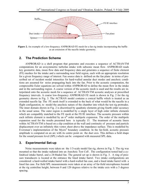
Baffle<br />
Duct intake<br />
Spinner<br />
2. The Prediction Scheme<br />
ANPRORAD is a shell program that generates and executes a sequence <strong>of</strong> ACTRAN/TM<br />
computations for an axisymmetric turb<strong>of</strong>an intake with subsonic mean flow. ANPRORAD reads<br />
key geometric data, mean flow data and frequency data and generates a sequence <strong>of</strong> finite element<br />
(FE) meshes for the intake and a surrounding near field region, each with an appropriate resolution<br />
for a given frequency range <strong>of</strong> interest. Fan source data is defined on the fan plane in terms <strong>of</strong> prescribed<br />
set <strong>of</strong> incident modal intensities for hard-walled annular duct modes and anechoic conditions<br />
are assumed for <strong>noise</strong> propagating back into the fan. Prior to the acoustic computation, the<br />
compressible Euler equations are solved within ANPRORAD to define the mean flow in the intake<br />
and in the surrounding region. A coarse version <strong>of</strong> the acoustic mesh is used and the results are interpol<strong>ated</strong><br />
onto the acoustic mesh for a sequence <strong>of</strong> ACTRAN/TM acoustic analyses at prescribed<br />
frequency intervals. A coarse low-frequency ANPRORAD FE mesh is shown in Fig. 2 for the rig<br />
geometry shown in Fig. 3. The ACTRAN model contains a conical baffle which is tre<strong>ated</strong> as an<br />
extended nacelle lip. The FE mesh itself is extended to the back <strong>of</strong> what would be the nacelle in a<br />
flight configuration, to model the anechoic nature <strong>of</strong> the chamber into which the test rig protrudes.<br />
The inner domain shown in Fig. 2 is discretised by quadratic elements giving fourth order accuracy<br />
in the usual sense. The outer region is modelled by a single layer <strong>of</strong> high order infinite elements<br />
which are compatibly matched to the FE mesh at the FE/IE interface. The acoustic pressure within<br />
each infinite element is modelled by an n th order multipole expansion. The order <strong>of</strong> the multipole<br />
expansion used for the results presented here is typically 15. The treatment <strong>of</strong> acoustic liners<br />
within ACTRAN/TM is based on a slip condition at the wall and continuity <strong>of</strong> pressure and particle<br />
displacement over an infinitely thin vortex sheet above the impedance surface. This is modelled by<br />
Eversman’s implementation <strong>of</strong> the Myers 6 boundary condition. In the far-field, acoustic pressure<br />
amplitude is computed on an arc with its centre point on the duct axis. This defines a field shape<br />
for the sound pressure level (SPL) which can be compared with measured SPL data.<br />
3. Experimental Set-up<br />
FE/IE interface<br />
Fan plane<br />
Figure 2. An example <strong>of</strong> a low-frequency ANPRORAD FE mesh for a fan rig intake incorporating the baffle<br />
as an extension <strong>of</strong> the nacelle intake geometry.<br />
Noise measurements were taken on the 1/3-scale model fan rig, shown in Fig. 3. The rig was<br />
mounted so that the intake <strong>radi</strong><strong>ated</strong> into an Anechoic Test Cell . The configuration tested had a cylindrical<br />
intake barrel, and a 24-bladed fan. The general set up is shown in Fig. 3. A ring <strong>of</strong> pressure<br />
transducers is loc<strong>ated</strong> at the entrance the lined intake barrel. Two intake configurations are<br />
considered: a hard-walled intake barrel with a hard-walled fan case, and a lined intake barrel with a<br />
lined fan case. Far field SPL measurements were taken at an array <strong>of</strong> far-field microphones loc<strong>ated</strong><br />
at the rig centreline height, between 0 and 120 degrees relative to the intake axis with a 5 degrees<br />
spacing.<br />
3