validation of caa prediction of noise radi- ated from turbofan intakes
validation of caa prediction of noise radi- ated from turbofan intakes
validation of caa prediction of noise radi- ated from turbofan intakes

You also want an ePaper? Increase the reach of your titles
YUMPU automatically turns print PDFs into web optimized ePapers that Google loves.
16 th International Congress on Sound and Vibration, Kraków, Poland, 5–9 July 2009<br />
4<br />
TCS<br />
Baffle<br />
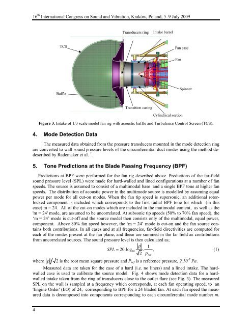
Figure 3. Intake <strong>of</strong> 1/3 scale model fan rig with acoustic baffle and Turbulence Control Screen (TCS).<br />
4. Mode Detection Data<br />
Transducers ring Intake barrel<br />
Transition casing<br />
Fan case<br />
Cylindrical section<br />
The measured data obtained <strong>from</strong> the pressure transducers mounted in the mode detection ring<br />
are converted to wall sound pressure levels <strong>of</strong> the circumferential duct modes using the method dedescribed<br />
by Rademaker et al. 7 .<br />
5. Tone Predictions at the Blade Passing Frequency (BPF)<br />
Spinner<br />
Predictions at BPF were performed for the fan rig described above. Predictions <strong>of</strong> the far-field<br />
sound pressure level (SPL) were made for hard-walled and lined configurations at a number <strong>of</strong> fan<br />
speeds. The source is assumed to consist <strong>of</strong> a multimodal base and a single BPF tone at higher fan<br />
speeds. The distribution <strong>of</strong> acoustic power in the multimode source is modelled by assuming equal<br />
power per mode for all cut-on modes. When the fan tip speed is supersonic, an additional rotorlocked<br />
component is included which corresponds to the first <strong>radi</strong>al BPF tone for which (in this<br />
case) m = 24. All <strong>of</strong> the cut-on modes which are included in the mutimodal content, as well as the<br />
'm = 24' mode, are assumed to be uncorrel<strong>ated</strong>. At subsonic tip speeds (50% to 70% fan speed), the<br />
‘m = 24’ mode is cut-<strong>of</strong>f and the source model then consists only <strong>of</strong> the multimodal, equal power,<br />
component. Above 80% fan speed however, the ‘m = 24’ mode is cut-on and the fan source contains<br />
both contributions. In all cases and at all frequencies, far-field directivities are computed for<br />
each <strong>of</strong> the modes present at the fan plane, and these are summed in the far field as contributions<br />
<strong>from</strong> uncorrel<strong>ated</strong> sources. The sound pressure level is then calcul<strong>ated</strong> as;<br />
p 1<br />
SPL = 20. log10<br />
. , (1)<br />
2 pref<br />
where p 2 is the root mean square pressure and Pref is a reference pressure, 2.10 -5 Pa.<br />
Measured data are taken for the case <strong>of</strong> a hard (i.e. no liners) and a lined intake. The hardwalled<br />
case is used to calibrate the source model. Fig. 4 shows mode detection data for a hardwalled<br />
intake taken <strong>from</strong> the ring <strong>of</strong> transducers close to the outlet flare (see Fig. 3). The measured<br />
SPL on the wall is sampled at a frequency which corresponds, at each fan operating speed, to an<br />
'Engine Order' (EO) <strong>of</strong> 24, corresponding to BPF for a 24 bladed fan. At each fan speed the measured<br />
data is decomposed into components corresponding to each circumferential mode number m.<br />
Fan