Elsevier Editorial System(tm) for Hearing Research Manuscript Draft ...
Elsevier Editorial System(tm) for Hearing Research Manuscript Draft ...
Elsevier Editorial System(tm) for Hearing Research Manuscript Draft ...

Create successful ePaper yourself
Turn your PDF publications into a flip-book with our unique Google optimized e-Paper software.
108<br />
109<br />
110<br />
111<br />
112<br />
113<br />
114<br />
115<br />
116<br />
117<br />
118<br />
119<br />
120<br />
121<br />
122<br />
123<br />
124<br />
125<br />
126<br />
127<br />
128<br />
129<br />
130<br />
131<br />
132<br />
133<br />
134<br />
135<br />
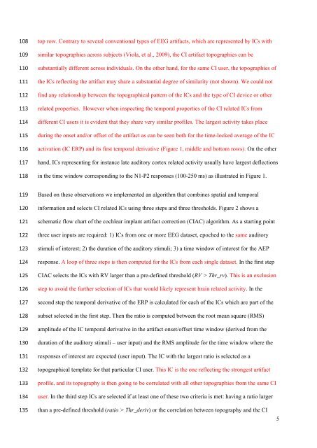
top row. Contrary to several conventional types of EEG artifacts, which are represented by ICs with<br />
similar topographies across subjects (Viola, et al., 2009), the CI artifact topographies can be<br />
substantially different across individuals. On the other hand, <strong>for</strong> the same CI user, the topographies of<br />
the ICs reflecting the artifact may share a substantial degree of similarity (not shown). We could not<br />
find any relationship between the topographical pattern of the ICs and the type of CI device or other<br />
related properties. However when inspecting the temporal properties of the CI related ICs from<br />
different CI users it is evident that they share very similar profiles. The largest activity takes place<br />
during the onset and/or offset of the artifact as can be seen both <strong>for</strong> the time-locked average of the IC<br />
activation (IC ERP) and its first temporal derivative (Figure 1, middle and bottom rows). On the other<br />
hand, ICs representing <strong>for</strong> instance late auditory cortex related activity usually have largest deflections<br />
in the time window corresponding to the N1-P2 responses (100-250 ms) as illustrated in Figure 1.<br />
Based on these observations we implemented an algorithm that combines spatial and temporal<br />
in<strong>for</strong>mation and selects CI related ICs using three steps and three thresholds. Figure 2 shows a<br />
schematic flow chart of the cochlear implant artifact correction (CIAC) algorithm. As a starting point<br />
three user inputs are required: 1) ICs from one or more EEG dataset, epoched to the same auditory<br />
stimuli of interest; 2) the duration of the auditory stimuli; 3) a time window of interest <strong>for</strong> the AEP<br />
response. A loop of three steps is then computed <strong>for</strong> the ICs from each single dataset. In the first step<br />
CIAC selects the ICs with RV larger than a pre-defined threshold (RV > Thr_rv). This is an exclusion<br />
step to avoid the further selection of ICs that would likely represent brain related activity. In the<br />
second step the temporal derivative of the ERP is calculated <strong>for</strong> each of the ICs which are part of the<br />
subset selected in the first step. Then the ratio is computed between the root mean square (RMS)<br />
amplitude of the IC temporal derivative in the artifact onset/offset time window (derived from the<br />
duration of the auditory stimuli – user input) and the RMS amplitude <strong>for</strong> the time window where the<br />
responses of interest are expected (user input). The IC with the largest ratio is selected as a<br />
topographical template <strong>for</strong> that particular CI user. This IC is the one reflecting the strongest artifact<br />
profile, and its topography is then going to be correlated with all other topographies from the same CI<br />
user. In the third step ICs are selected if at least one of these two criteria is met: having a ratio larger<br />
than a pre-defined threshold (ratio > Thr_deriv) or the correlation between topography and the CI<br />
5