You also want an ePaper? Increase the reach of your titles
YUMPU automatically turns print PDFs into web optimized ePapers that Google loves.
5.4 <strong>Card</strong> detection and PHYSLP functions with CDI and CDO pin<br />
5.4.1 General<br />
The <strong>CFast</strong> card connector contains two signals, CDI and CDO. These signals enable two functions:<br />
a. <strong>Card</strong> Detect. This function enables the host to detect when the card is fully inserted. For example, the<br />
host may wish to power up the card only after it is inserted, or turn on an LED when the card is properly<br />
inserted.<br />
b. PHYSLP. This function is a <strong>CFast</strong> power management protocol which may be invoked when the SATA<br />
connection is in Slumber mode. Please see the <strong>CFast</strong> specifications for a complete description. The<br />
purpose of this function is to enable the device to turn off the SATA PHY completely, saving power. The<br />
host may turn off its own PHY when invoking this function.<br />
<strong>Swissbit</strong> F-2x0 support <strong>Card</strong> detect and PHYSLP functionality<br />
This section explains recommended methods for the host to interface with the card so that the card will not be<br />
damaged, and to ensure compatibility between the card and the host regarding the above described functions.<br />
5.4.2 Connection when the host uses the <strong>Card</strong> Detect functionality only<br />
The host needs to take into account the following restrictions:<br />
a. CDI and CDO are shorted together on the <strong>CFast</strong> card.<br />
b. The card may not have Vcc connected directly to CDI or to CDO.<br />
(The newest F-2x0 cards have a serial resistor between CDI and controller)<br />
c. The CDI – CDO signal on the F-2x0 card is connected to a card controller input pin.<br />
d. The card doesn’t actively drive the CDI or CDO signals.<br />
Based on the above, the following is recommended:<br />
a. CDI will be connected to Gnd.<br />
b. CDO will be connected to an input port on the host controller.<br />
c. CDO will be connected to a pull-up resistor on the host. The value of the resistor is calculated so that the<br />
voltage drop across the resistor when the card CDO is connected and CDI is not connected will not exceed<br />
0.4V. The leakage current of the card controller is up to 1A. As an example, if the host controller<br />
leakage is also 1A, the pull-up resistor may have a value of up to 200K . It is recommended that the<br />
pull-up resistor value will be as high as possible in order to have no effect on the card controller and to<br />
conserve power.<br />
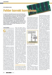
See Figure 2<br />
Figure 2: <strong>CFast</strong> connection for <strong>Card</strong> Detect functionality only<br />
Gnd<br />
CDI<br />
Host Electronics<br />
Host<br />
Controller<br />
<strong>CFast</strong> card<br />
Input<br />
only<br />
Controller<br />
Input<br />
only<br />
<strong>Swissbit</strong> AG <strong>Swissbit</strong> reserves the right to change products or specifications without notice. Revision: 1.20<br />
Industriestrasse 4<br />
CH-9552 Bronschhofen www.swissbit.com F-<strong>240</strong>_data_sheet_CA-HxBV_Rev120.doc<br />
Switzerland industrial@swissbit.com Page 11 of 60<br />
CDO<br />
Internal connection<br />
(optional)<br />
Vcc<br />
Pull-up<br />
resistor,<br />
100KOhm to<br />
200 KOhm