Create successful ePaper yourself
Turn your PDF publications into a flip-book with our unique Google optimized e-Paper software.
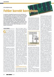
Table 67: Write FPDMA queued<br />
Task File Register 15:8 7 6 5 4 3 2 1 0<br />
COMMAND - 61h<br />
DRIVE/HEAD - FUA 1 nu 0 nu<br />
CYLINDER HI LBA (47:40) LBA23:16<br />
CYLINDER LOW LBA (39:32) LBA15:8<br />
SECTOR NUM LBA (31:24) LBA7:0<br />
SECTOR COUNT nu NCQ Tag nu<br />
FEATURES The number of logical sectors to be transferred. A value of 0000h indicates that 65,536<br />
logical sectors are to be transferred.<br />
For further details see the ATA8 specification.<br />
6.45 Write Multiple Command (C5h)<br />
This command is similar to the Write Sectors command. The Drive sets BSY within 400ns of accepting the<br />
command. Interrupts are not presented on each sector but on the transfer of a block which contains the<br />
number of sectors defined by Set Multiple. Command execution is identical to the Write Sectors operation except<br />
that the number of sectors defined by the Set Multiple command is transferred without intervening interrupts.<br />
DRQ qualification of the transfer is required only at the start of the data block, not on each sector. The block<br />
count of sectors to be transferred without intervening interrupts is programmed by the Set Multiple Mode<br />
command, which must be executed prior to the Write Multiple command.<br />
When the Write Multiple command is issued, the Sector Count Register contains the number of sectors (not the<br />
number of blocks or the block count) requested. If the number of requested sectors is not evenly divisible by the<br />
sector/block, as many full blocks as possible are transferred, followed by a final, partial block transfer. The<br />
partial block transfer is for n sectors, where:<br />
n = (sector count) module (block count).<br />
If the Write Multiple command is attempted before the Set Multiple Mode command has been executed or when<br />
Write Multiple commands are disabled, the Write Multiple operation will be rejected with an aborted command<br />
error.<br />
Errors encountered during Write Multiple commands are posted after the attempted writes of the block or partial<br />
block transferred. The Write command ends with the sector in error, even if it is in the middle of a block.<br />
Subsequent blocks are not transferred in the event of an error. Interrupts are generated when DRQ is set at the<br />
beginning of each block or partial block.<br />
The Command Block Registers contain the cylinder, head and sector number of the sector where the error<br />
occurred and the Sector Count Register contains the residual number of sectors that need to be transferred for<br />
successful completion of the command. For example, each block has 4 sectors, a request for 8 sectors is issued<br />
and an error occurs on the third sector. The Sector Count Register contains 6 and the address is that of the third<br />
sector.<br />
Note: The current revision of the Drive only supports a block count of 1 as indicated in the Identify Drive<br />
Command information. The Write Multiple command is provided for compatibility with future products which<br />
may support a larger block count.<br />
Table 68 defines the Write Multiple command Byte sequence.<br />
Table 68: Write Multiple<br />
Task File Register 7 6 5 4 3 2 1 0<br />
COMMAND C5h<br />
DRIVE/HEAD 1 LBA 1 D Head (LBA 27:24)<br />
CYLINDER HI Cylinder High (LBA23:16)<br />
CYLINDER LOW Cylinder Low (LBA15:8)<br />
SECTOR NUM Sector number (LBA7:0)<br />
SECTOR COUNT Sector Count<br />
FEATURES nu<br />
6.46 Write Multiple Ext (39h) 48bit LBA<br />
The Write Multiple Ext command is similar to the Write Multiple command, except that LBA addressing is<br />
mandatory, the LBA associated with this command is a 48 bit address, and the sector count field is a 16 bit field.<br />
The second (lower in the table) part of each 16 bit field can be written to or read from by setting the HOB bit of<br />
the Device Control Register to 1 before reading or writing the field. Reading or writing the task file shall reset the<br />
HOA bit to 0.<br />
<strong>Swissbit</strong> AG <strong>Swissbit</strong> reserves the right to change products or specifications without notice. Revision: 1.20<br />
Industriestrasse 4<br />
CH-9552 Bronschhofen www.swissbit.com F-<strong>240</strong>_data_sheet_CA-HxBV_Rev120.doc<br />
Switzerland industrial@swissbit.com Page 42 of 60