Aircraft Wake Detection Using Bistatic Radar: Analysis of ...
Aircraft Wake Detection Using Bistatic Radar: Analysis of ...
Aircraft Wake Detection Using Bistatic Radar: Analysis of ...

Create successful ePaper yourself
Turn your PDF publications into a flip-book with our unique Google optimized e-Paper software.
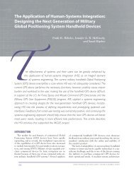
R. J. IANNUZZELLI ET AL.<br />
20<br />
0<br />
Time (s) 40<br />
–20<br />
–40<br />
–1500 –1000 –500 0 500 1000 1500<br />
Doppler frequency (Hz)<br />
Figure 9. Interference shown for a vehicle traveling 40 mph on<br />
Rte. 176.<br />
over the common volume. At this point, most <strong>of</strong> the<br />
voice annotation centered on the vortex smoke trails<br />
as seen by the receiver video camera. When the transmit<br />
container saw smoke in the transmit monitor, radio<br />
contact was made and notes taken at the receiver<br />
container specifying the degree <strong>of</strong> visual collaboration<br />
<strong>of</strong> smoke in the cameras at the receiver and transmit<br />
sites. This procedure worked well in establishing which<br />
<strong>of</strong> the many data runs were worth further investigation.<br />
Observed Vortex Behavior<br />
The behavior <strong>of</strong> the wingtip vortices was videotaped<br />
during the three test periods. Near-surface temperature<br />
and wind data were recorded at the radar<br />
receiver site. Recording devices were not allowed near<br />
or above the runway surface. Operations during the<br />
evening hours provided the most stable atmospheric<br />
conditions for the first test period. Because <strong>of</strong> the time<br />
change to Eastern Standard Time after the first tests<br />
and the heavy airline activity, the second and third<br />
tests were conducted during the morning and afternoon<br />
hours. A general description <strong>of</strong> the wind conditions<br />
and the vortex behavior during each test period<br />
is given in the following paragraphs.<br />
The first test began at 5:20 p.m. on 23 September.<br />
Winds were 5 to 10 kt along the runway centerline.<br />
The C-130 made 20 passes by the APL test site at<br />
altitudes ranging from 15 to about 107 m above ground<br />
level (AGL). As noted earlier, the left wingtip smoker<br />
worked, but the right tip had malfunctioned. The lefttip<br />
vortex lasted more than 2 min after the C-130 flyby.<br />
The vortex remained near the runway centerline at<br />
approximately 12 m AGL. In some cases, the vortex<br />
passed through the boresight camera’s view and would<br />
reappear shortly thereafter, giving the false impression<br />
that the vortex was rising. Instead, it remained near<br />
about 12 m AGL but underwent a wavelike oscillation.<br />
The peak <strong>of</strong> the wave motion reappeared in the boresight<br />
camera’s view.<br />
The first test date provided the best atmospheric<br />
conditions for vortex longevity, but posttest analysis<br />
determined that the radar’s common volume was too<br />
low and the local traffic on Dorsey Road caused too<br />
much interference in the radar data.<br />
The second test started at 9:50 a.m. on 29 October.<br />
Again, the right-tip smoker had malfunctioned. Initially,<br />
winds were approximately 15 to 20 kt across the<br />
runway. In some cases, the C-130 was instructed to fly<br />
at two wingspans about 80 m to the right <strong>of</strong> the runway<br />
centerline in hopes that the vortices would pass<br />
through the radar’s common volume. After six passes,<br />
the winds decreased to light and variable and the<br />
C-130 was instructed to fly over the runway centerline.<br />
Fifteen passes were made by the C-130 until the BWI<br />
tower terminated testing owing to increasing commercial<br />
air traffic. The second half <strong>of</strong> this test provided the<br />
best radar data.<br />
The third and final test date was 10 December. The<br />
malfunction in the right-tip smoker had been corrected,<br />
thereby allowing the observation <strong>of</strong> the interaction<br />
306 JOHNS HOPKINS APL TECHNICAL DIGEST, VOLUME 19, NUMBER 3 (1998)<br />
(a)<br />
(b)<br />
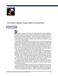
Figure 10. The NASA C-130 research aircraft with generator on<br />
left wing. (a) Trailing vortex seen on approach to BWI. (b) Smokemarked<br />
vortex as seen several seconds after the C-130 passed<br />
by (a).