NOW! 12-13 - Telos
NOW! 12-13 - Telos
NOW! 12-13 - Telos

Create successful ePaper yourself
Turn your PDF publications into a flip-book with our unique Google optimized e-Paper software.
OMNIA | FM-STEREO TRANSMISSION | TECHNOLOGY ARTICLE<br />
54<br />
SINGLE SIDEBAND SUPPRESSED CARRIER (SSBSC)<br />
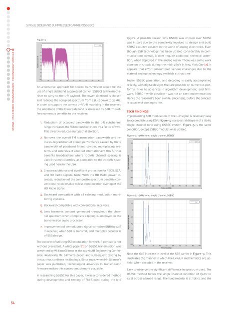
Figure-3<br />
An alternative approach for stereo transmission would be the<br />
use of single sideband suppressed carrier (SSBSC) as the mecha-<br />
nism to carry to the L-R payload. The lower sideband is chosen<br />
as it reduces the occupied spectrum from 53kHz down to 38kHz.<br />
In order to support the correct L+R/L-R matrixing in the receiver,<br />
the amplitude of the lower sideband is increased by 6dB. This of-<br />
fers numerous beneits to the receiver:<br />
1. Reduction of occupied bandwidth in the L-R subchannel<br />
range increases the FM modulation index by a factor of two.<br />
This directly reduces multipath distortion.<br />
2. Narrows the overall FM transmission bandwidth and re-<br />
duces degradation of stereo performance caused by inite<br />
bandwidth of passband ilters, cavities, multiplexing sys-<br />
tems, and antennas. If adopted internationally, this further<br />
beneits broadcasters where 100kHz channel spacing is<br />
used in some countries, as compared to the 200kHz spac-<br />
ing used here in the USA.<br />
3. Creates additional and signiicant protection for RBDS, SCA,<br />
and HD Radio signals. Note: With the HD Radio power in-<br />
crease, reduction of the composite spectrum beneits con-<br />
ventional receivers due to less demodulation overlap of the<br />
HD Radio signal.<br />
4. Backward compatible with all existing modulation moni-<br />
toring systems.<br />
5. Backward compatible with conventional receivers.<br />
6. Less harmonic content generated throughout the chan-<br />
nel spectrum when composite clipping is employed in the<br />
transmission audio processor.<br />
7. Improvement of demodulated signal-to-noise (SNR) by 4dB<br />
in receiver, when SSB is transmit, and multiplex decoder is<br />
of SSB design.<br />
The concept of utilizing SSB modulation for the L-R payload is not<br />
without precedent. A white paper [1] on SSBSC transmission was<br />
presented by William Gillman at the 1997 NAB Engineering Confer-<br />
ence. Reviewing Mr. Gillman’s paper, and subsequent testing by<br />
this author, conirms his indings. Since 1997, when Mr. Gillman’s<br />
paper was published, technological advances in transmission<br />
irmware makes this concept much more plausible.<br />
In researching SSBSC for this paper, it was a considered method<br />
during development and testing of FM-Stereo during the late<br />
1950’s. A possible reason why DSBSC was chosen over SSBSC<br />
was in part due to the complexity involved to design and build<br />
SSBSC circuitry, reliably, in the world of analog electronics. Even<br />
though SSB technology has been utilized considerably in com-<br />
munications overall, it does require additional technical atten-<br />
tion, when deployed in the analog realm. There was some work<br />
done on this topic during the mid 1980’s in New York City [2]. It<br />
appears that effort encountered various challenges due to the<br />
state of analog technology available at that time.<br />
Today, SSBSC generation, and decoding is easily accomplished<br />
reliably, with digital designs that are possible on numerous plat-<br />
forms. Prior to advances in algorithm development, and irm-<br />
ware, SSBSC – while possible – was not an easy implementation.<br />
Hence the reason it’s been awhile, since 1997, before the concept<br />
is capable of coming to life.<br />
TECH FINDINGS<br />
Implementing SSB modulation of the L-R signal is relatively easy<br />
to accomplish using DSP. Figure–4 is a spectral diagram of a 15kHz<br />
single channel tone using DSBSC system. Figure–5 is the same<br />
condition, except SSBSC modulation is utilized.<br />
Figure–4, 15kHz tone, single channel, DSBSC<br />
Figure–5, 15kHz tone, single channel, SSBSC<br />
Note the 6dB increase in level of the SSB carrier in Figure–3. This<br />
illustrates the manner in which the L+R/L-R mathematics are up-<br />
held, when decoded in the receiver.<br />
Easy to observe the signiicant difference in spectrum used. The<br />
DSBSC method forces the single channel condition of 15kHz to<br />
exist across a broad range. The fundamental is at 15kHz, and the