

POWER-MASTER 500 - Victor Technologies
POWER-MASTER 500 - Victor Technologies
POWER-MASTER 500 - Victor Technologies

Create successful ePaper yourself
Turn your PDF publications into a flip-book with our unique Google optimized e-Paper software.
<strong>POWER</strong>-<strong>MASTER</strong> <strong>500</strong> 430581-004<br />
The me ter will au to mat i cally switch over to ac tual<br />
amps or volts while weld ing, de pend ing on the<br />
po si tion of the me ter Amps/Volts switch.<br />
7 – Me ter Amps/Volts Switch : This two-position<br />
tog gle switch is used to se lect whether the dig i tal<br />
me ter will dis play amps or volts. To pre set weld<br />
am per age for GTAW, SMAW or CAG, place this<br />
switch in the AMPS po si tion. To pre set weld volt -<br />
age for GMAW, place this switch in the VOLTS<br />
mode. Af ter an arc has been ini ti ated, this switch<br />
al lows ei ther ac tual weld amps or weld volts to be<br />
dis played on the me ter.<br />
8 – Re mote/Lo cal Switch: The re mote/lo cal<br />
tog gle switch is used to se lect ei ther front panel<br />
con trol of out put amps/volts (LO CAL mode), or<br />
re mote con trol of out put amps/volts through the<br />
19 pin or 14 pin re cep ta cles lo cated on the rear<br />
panel (RE MOTE mode). For GTAW mode, the<br />
max i mum out put cur rent must be pre set by the<br />
front panel Amps/Volts con trol pot. For all other<br />
modes, the re mote con trol is full out put of the ma -<br />
chine.<br />
9– Amps/Volts Con trol: This con trol pot. sets<br />
the out put amps or volts de pend ing on the weld<br />
pro cess. Clock wise is in creas ing out put. For all<br />
modes ex cept GTAW, this con trol is only ac tive<br />
when the LO CAL/RE MOTE switch is in the LO -<br />
CAL mode. For GTAW this con trol pot. is used to<br />
set the max i mum weld cur rent avail able to a foot<br />
pedal or hand con trol. To pre set max i mum out put<br />
for GTAW, place the LO CAL/RE MOTE switch in<br />
the LO CAL mode and set the max i mum de sired<br />
am per age on the dig i tal me ter. (The me ter<br />
amps/volts switch must be in the amps po si tion).<br />
Place the LO CAL/RE MOTE switch in the RE -<br />
MOTE mode to ac ti vate foot pedal con trol.<br />
10 – Arc Force/In duc tance Con trol: This con -<br />
trol pot. is ac tive for SMAW (Stick) and GMAW<br />
(Mig). In SMAW mode, this pot. con trols the<br />
amount of arc force or dig that the arc has. Max i -<br />
mum arc force is full clock wise, full coun -<br />
ter-clockwise is zero arc force. In GMAW mode,<br />
this be comes an in duc tance con trol. Max i mum<br />
in duc tance is full clock wise. Higher in duc tance<br />
set tings make the arc “softer” with less spat ter.<br />
Lower in duc tance set tings give a stron ger “driv -<br />
ing” arc. The in duc tance should be set ac cord ing<br />
to the type of wire and gas and de sired arc char -<br />
ac ter is tics de sired. Gen erally, the in duc tance<br />
con trol can be set at mid-range as a good start ing<br />
point.<br />
11 – Out put Neg a tive Ter mi nal: Con nec tion<br />
point for neg a tive weld ing lead.<br />
12 – Out put Pos i tive Ter mi nal: Con nec tion<br />
point for pos i tive weld ing lead.<br />
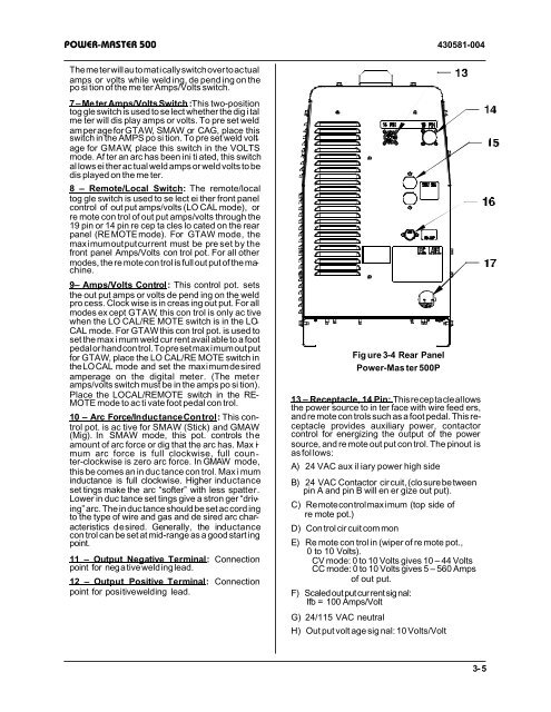
13 – Receptacle, 14 Pin: This re cep ta cle al lows<br />
the power source to in ter face with wire feed ers,<br />
and re mote con trols such as a foot pedal. This re -<br />
cep ta cle pro vides aux il iary power, contactor<br />
con trol for en er giz ing the out put of the power<br />
source, and re mote out put con trol. The pinout is<br />
as fol lows:<br />
A) 24 VAC aux il iary power high side<br />
B) 24 VAC Contactor cir cuit, (clo sure be tween<br />
pin A and pin B will en er gize out put).<br />
C) Re mote con trol max i mum (top side of<br />
re mote pot.)<br />
D) Con trol cir cuit com mon<br />
E) Re mote con trol in (wiper of re mote pot.,<br />
0 to 10 Volts).<br />
CV mode: 0 to 10 Volts gives 10 – 44 Volts<br />
CC mode: 0 to 10 Volts gives 5 – 560 Amps<br />
of out put.<br />
F) Scaled out put cur rent sig nal:<br />
Ifb = 100 Amps/Volt<br />
G) 24/115 VAC neu tral<br />
Fig ure 3-4 Rear Panel<br />
Power-Mas ter <strong>500</strong>P<br />
H) Out put volt age sig nal: 10 Volts/Volt<br />
3-5


